

Page 1
TableofContent
Page 2

2.Installation
Fanlessnonoisedesign
PaintedAluminumEnclosure
PassivePowerFactorCorrection(Optional)
SurgeCurrentProtection
InputTransientVoltageProtection
OverVoltageProtection
OverPowerProtection
ShortCircuitProtection
1.FunctionDescription
Herearesomeofthekeyfeatures:
1
Thispowersupplyisdesignedforpersonalcomputer.TherearesixDCoutputs:
+5V,-5V,+12V,-12V,+3.3V+5V,anditprovidespowertoallcomputer&
SB
systemsandperipheralswithmaximumprotection.
Thispowersupplyfamilyisdesignedw/ocoolingfanthereforeresultsin
completesilence.Heatgeneratedandraisedinthepowersupplyunitis
conductedviaheatsinkandfinallyreleasetotheair.
Itisrathersimpletoinstallthispowersupplytoyourpreciouscomputertower.
Followthestepsbelowtofinishtheinstallation.
Step1:Openthecomputertowercover;putthepowersupplyintothecorresponding
locationofthetower,andthenuserightscrews
tofixthepowersupply
Step2:PuttheMainPowerConnector,ATX12VConnector,S-ATAonnector,
PeripheralConnectorsandFloppyConnectorstothecorresponding
maleconnectorsofmain-board,peripheraldevices(i.e.HDD,CDROM
etc.)andfloppydriversrespectively.Whenyouconnectconnectors,please
payattentiontotheorientationofthembecauseofthedifferentholesizes.
Findtheproperorientationandpushdownfirmlymakingsurethatthe
pinsarealigned.
totower.
Page 3
2
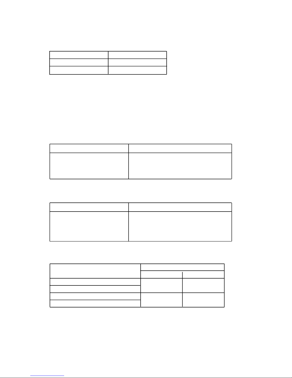
InputRange
100~120Vac
VoltSelectorSet
115
200~240Vac 230
3.InputRequirements
3.1.InputVoltage
Thepowersupplyshallbeoperatedattherangebelow:
3.2.Frequency
Theinputfrequencyrangeisfrom47Hzto63Hz.
3.3.InrushCurrent
Themax.inrushcurrentis45Afor115Vacand70Afor230Vac,respectively.
3.3.1.ColdStart
Conditions Limits
Conditions Limits
Model
ACInput
FL-550ATX(CF-300)
FL-350ATX(CF-350)
FL-420ATX(CF-400)
FL-480ATX(CF-480)
115Vac
230Vac
10A 5.5A
115/230Vac,fullload,
ambient25degreeC
NOcomponentoverstressordamage
shouldoccurtothepowersupply.
Inputfuseshallnotblow.
Turnoffat132/264Vacfull
loadfor1secretarythenturn
onatthepeakoftheinput
voltagecycleat25degreeC.
NOcomponentoverstressordamage
shouldoccurtothepowersupply.
Inputfuseshallnotblow.
3.5.Efficiency
Thepowersupplyefficiencyshallnotbelessthan75%atthemaximum
loadofsection4.2and115/230Vacinputvoltage.Whileathalfloadthe
valueshallreach77%min.
3.4.ACInputCurrent
3.3.2.WarmStart
8A 4A
Page 4
3
Output
Voltage
Range
MIN NOM MAX Unit
+5V
+12V
-5V
-12V
+3.3V
+5Vsb
±
5%
+4.75
+11.40
-4.50
-10.80
+3.14
+4.75
+5.00
+12.00
-5.00
-12.00
+3.30
+5.00
+5.00
+12.60
-5.50
-13.20
+3.47
+5.25
Volts
Volts
Volts
Volts
Volts
Volts
±
5%
±
10%
±
5%
±
5%
±
10%
4.Output
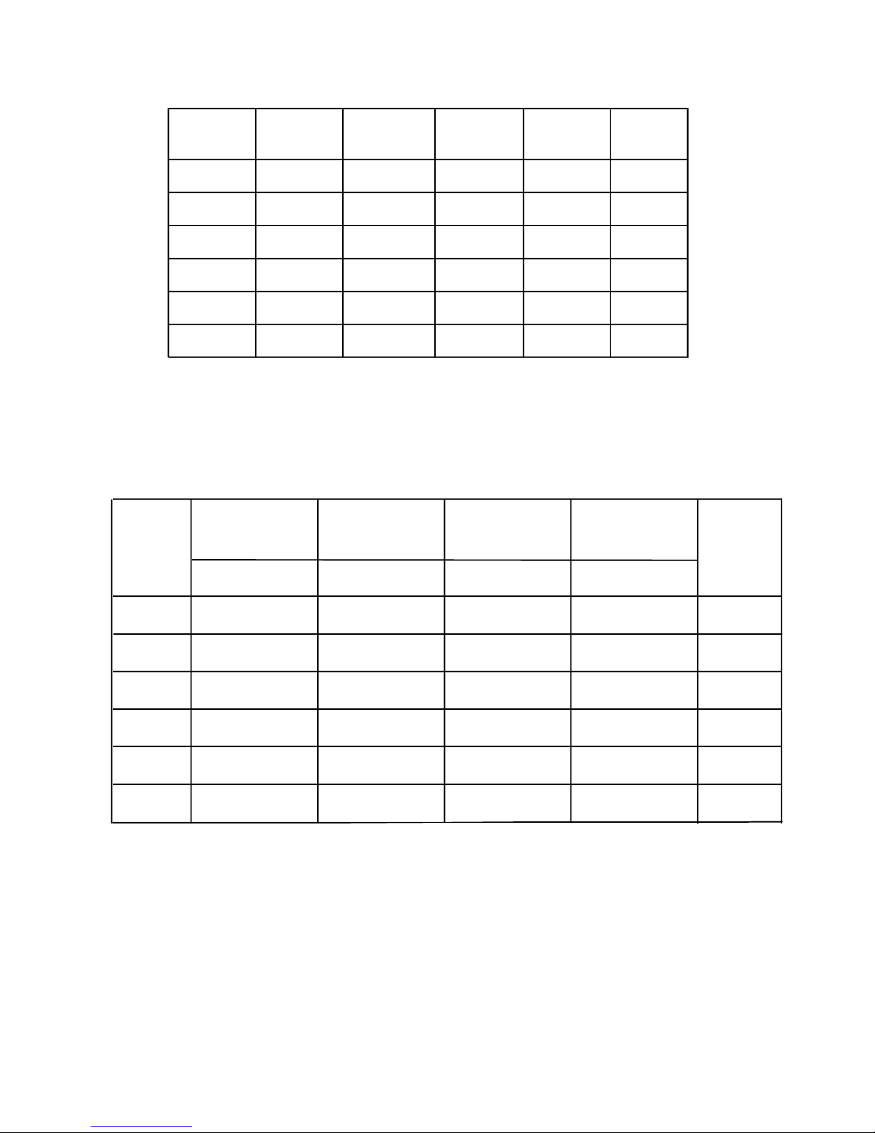
4.1.OutputRegulations
Note:Theoutputvoltageshouldbemeasuredattheterminalsofoutput
connector.
4.2.PowerDistributionConfiguration
4.3.CrossRegulation
TheDCloadsshallremainwithintherangesspecifiedin4.2Power
DistributionConfigurationandtheDCoutputvoltagesalsoshallremain
withintheregulationrangesspecifiedin4.1OutputRegulationswhen
measuredattheloadendoftheoutputconnectors.
+3.3V
+5V
+12V
-5V
-12V
+5Vsb
Max.350W
FL-350ATX
(CF-350)
FL-420ATX
(CF-400)
FL-480ATX
(CF-480)
Max.400W Max.480W
28A
35A
15A
0.5A
0.8A
2.5A
Max.300W
FL-550ATX
(CF-300)
25A
30A
15A
0.3A
0.8A
2A
30A
18A
1A
1A
2.5A
30A
45A
18A
1A
1A
2.5A
40A
Output
Rail
Cable
Color
Orange
Red
Yellow
White
Blue
Purple
Page 5
4
4.5.DCOutputVoltageRippleandNoise
DCOutput RippleMax. NoiseMax. Unit
+5V
+12V
-5V
-12V
+3.3V
+5Vsb
75
150
75
150
75
100
mV
mV
mV
mV
mV
mV
75
150
75
150
75
100
Note:Themeasurementsshouldbemadebycrossinga10uFelectrolytic
anda0.1uFceramicdiskcapacitorateachoutputmeasuringbandwidthfromDCto20MHz.Ifambienttemperatureisunder20or
over30,theACinputshouldbenominalinput.
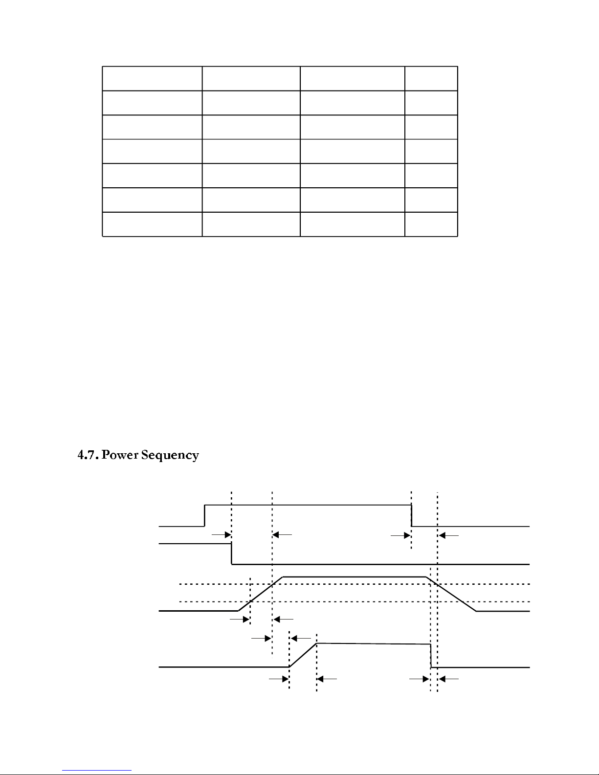
4.6.RemoteON/OFFControl
Thepowersupplyoutputsshallbeenabledwithanactive-lowTTLsignal.
WhenTTLsignalislow,theDCoutputsaretobeenabled.WhenTTL
signalishighoropencircuited,theDCoutputsaretobedisabled.Electronic
meansoramechanicalswitchmayactivatetheTTLsignal.AftertheTTL
signalisactivehigh,mustwaitfor3secondsbeforeactivelowagain.
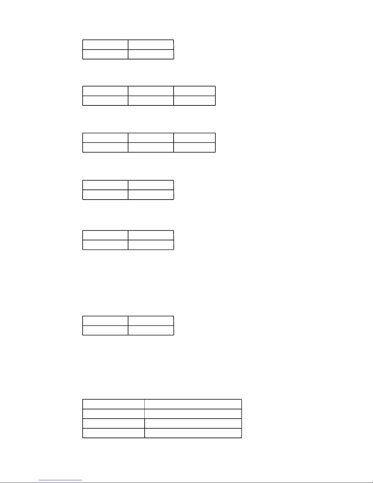
ACIN
PS_ON
O/P
PG
on
T1
T5
T2
T3
T4 T6
off
95%
10%
+12V
+5V
+3.3V
Page 6
5
MIN.
0.1
MAX.
20
Units
ms
MIN.
100
MAX.
500
Units
ms
MAX
500
Units
ms
MIN.
14
Units
ms
MIN.
1
Units
ms
DCOutput
+12V
TriggerVoltageRange
13.4~15.6V
+5V
+3.3V
5.74~7.0V
3.76~4.3V
MAX Units
10
ms
4.8.PowerOnTime(T1)
4.9.RiseTime(T2)
4.10.PowerGoodDelayTime(T3)
4.11.PowerGoodRiseTime(T4)
4.12.HoldUpTime(T5)
Thetestenvironmentis25degreeC&fullload@nominalinput.
4.13.PowerFailSignal(T6)
Powergoodsignalshallgotoadownlevel1msbefore+5Voutputvoltage
fallsbelowtheregulationlimitsduringPS-ONsignal
5.Protections
5.1.OverVoltageProtection
WhentheDCoutputs(+5V,+12Vand+3.3V)haveovervoltagecondition,
thepowersupplyshallprovidelatchmodeovervoltageprotection.
Page 7
6
5.2.ShortCircuitProtection
Ashortcircuitplacedonanyoutputshallcausenodamageorthepower
supplyshallshutdown.(Thecontactresistanceis0.05ohmwhenoutputs
shortcircuit.)
5.3.ProtectionReset
Whenthepowersupplylatchesintoshutdownconditionduetoafaulton
anoutput,theprotectionshallresetafterthefaulthasbeenremoved.Use
remoteon/offcontrolorrecycletheACpoweragainforatypicalof3seconds.
5.4.OverShoot
Anyoutputovershootatturnonshallbelessthan10%ofthenominaloutput
value(withresistiveload)asdescribedinsec.4.1.
5.5.OverPowerProtection
At115/230VacinputthepowersupplywillshutdownallDCoutputwithin
110%to160%offullload.
5.6.OverTemperatureProtection
Thepowersupplyshallgotolatchwhenitsinnerteperaturereaches100
degreeC.
6.Enviroment
6.1.Operation/StorageTemperatureRange
Operation:0to50
C
Storage:-20to80
C
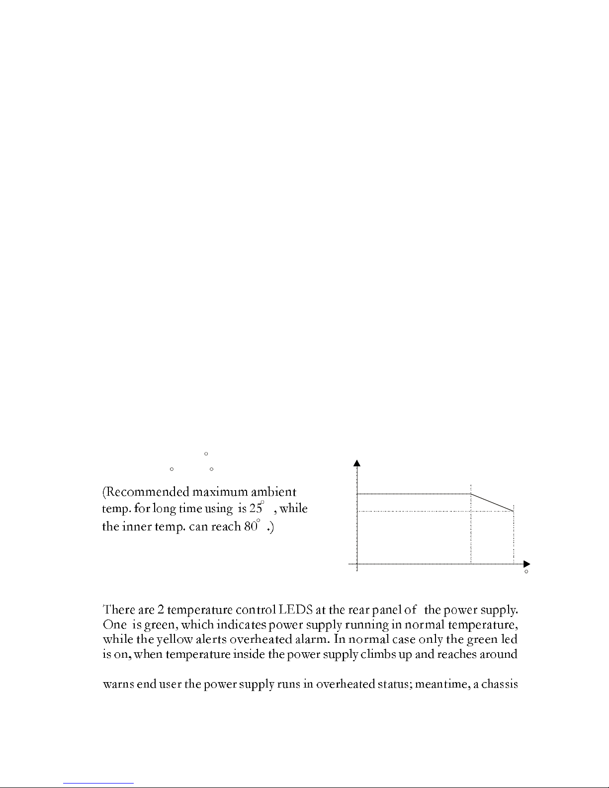
6.2.SmartTemp.ControlFeature(Option)
60degreeCorabove,thegreenledgoesoffandtheyellowoneturnson,
fanthatispoweredbythepowersupplythroughabig4pinmale
25 50 C
LOAD
100%
70%
25 50
LOAD
100%
70%
25 50
LOAD
100%
70%
100%
70%
25 5025 50
C
C
C
Page 8

7
Powerconnectorstartstorotatetopulltheinnerheatoutside.Whenpower
supplyinnertemperaturedecreasesbelow60degreeC,thefanstops,theyellow
ledturnsoffandthegreenturnsonagain.Inthiswaytoachievebalancebetween
heatandnoise,andrealizethemostpossiblesilenceofthesystemunder
preconditionthesystemworksproperly.
6.3.Humidity(nonecondensing)
Operation:20%to85%RH
Storage:10%to95%RH
6.4.Altitude
Operation:to10,000ft
Storage:to50,000ft
7.RegulatoryCompliance
UL60950-1
CAN/CSA-C22.2NO.60950-1
TUVEN60950-1
FCCpart15subpartBClassB
8.DielectricVoltageWithstand(HI-POT)
Thepowersupplyshallwithstandfor2secondswithoutbreakdownthe
applicationofan1800Vacsupplyvoltageappliedbetweenbothinputline
andchassis(10mAACCutoffcurrent).Isolatingtransformersshallsimilarity
withstand4242Vdcappliedbetweenbothprimaryandsecondarywindings
foraminimumofoneminute.
9.MTBF
ThepowersupplyshallhaveaminimumMTBFatcontinuousoperationof
50,000hoursat100%load,therecommendedambienttemperatureof25
degreeCandamaximuminnertemperatureofthepowersupplyat80degree
Cfor230Vac/50Hzand115Vac/60Hz
10.Precaution
shock!
10.1.Donotopenthetopcoverofthepowersupplycase.
10.2.Pleasekeepthepowersupplyfromhumidity.
Page 9
8
resultinasystemshutdown.
11.3.Don'tattempttoremovethefrontpanelheatsinkatanytime,oritmay
11.4.Don'thand-touchanypartsoftheHIGHTEMPERATURE!
enclosurewhileoperation.
11.5.Flammablematerialsmustkeepfarfromthefrontpanelheatsink.
11.SimpleMaintenance
11.2.DoesInputVoltagesetinpowersupplycorrespondtothemain
Sourceinyourenvironment?
11.3Pleasechecktheoutputconnectorsplugginginproperdirectionand
connectingfirmly.
11.1.Doespowercordindeedplugintoelectricaloutlet?
11.4Pleasechecktheoutputconnectorsplugginginproperdirectionand
connectingfirmly.
11.5.Havingcheckedaboveitems,ifthepowersupplystilldoesnotfunction,
pleasesenditbacktoyourretailerordistributorforrepair
thefollowingitems:
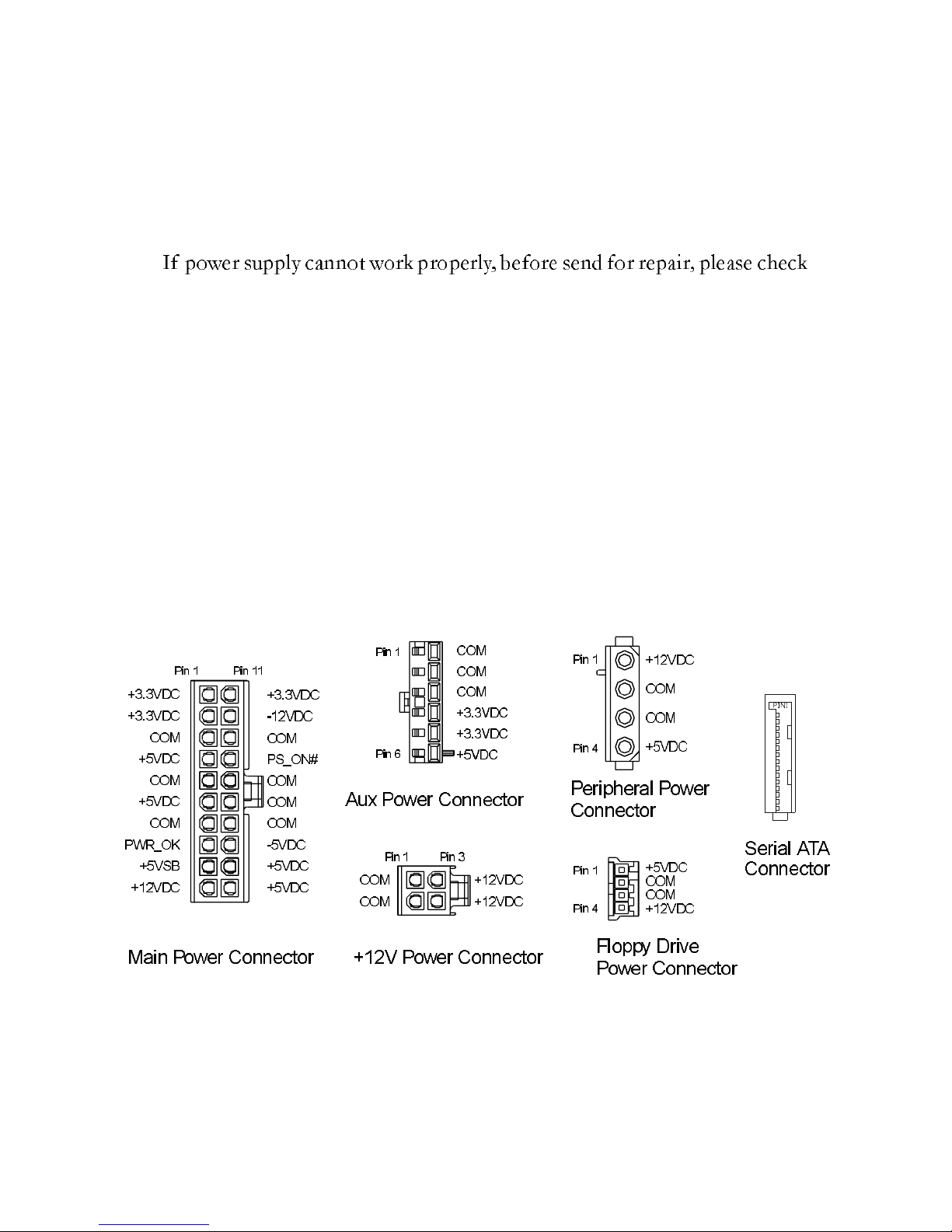
12.PowerConnectorDrawing
SerialATA
Connector
+3.3VDC
COM
+5VDC
+12VDC
+3.3VDC
+3.3VDC
COM
COM
+5VDC
+5VDC
COM
COM
COM
+12VDC
+12VDC
Pin-sideview,nottoscale
Page 10
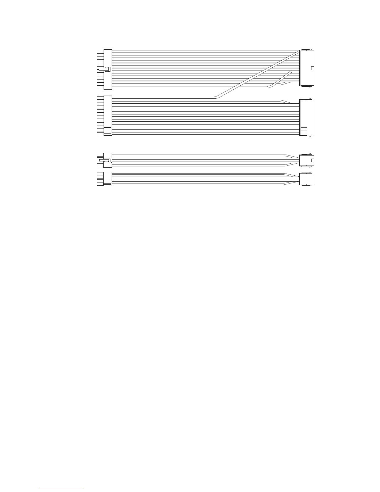
13.Cableadaptordrawing
Female24Pin
Female8Pin
Male20Pin
Male4Pin
100720#BLACK
100720#YELLOW
100720#ORANGE
100720#YELLOW
100718#RED
100718#RED
100720#YELLOW
100718#PURPLE
100718#GRAY
100718#BLACK
100718#BLACK
100718#BLACK
100718#ORANGE
100718#ORANGE
100720#BLACK
100720#RED
100718#RED
100720#ORANGE
100718#BLUE
100718#BLACK
100718#GREEN
100718#BLACK
100718#BLACK
100718#BLACK
100718#WHITE
100720#RED
1
8
4
5
1
12
24
13
100720#YELLOW
100720#YELLOW
100720#YELLOW
100720#BLACK
100720#BLACK
100720#BLACK
9
 Loading...