

Page 1

Table of Content
1 Function Description...................................................
2 How to Setup........................................... ...............
3 Specifications..........................................................
4 Precaution..............................................................
5 Simple Maintainance...................................................
6 Mechanical Diagram....................................................
1
4
5
1
5
1
Page 2
1. Function Description
This power supply is designed for personal computer. There are eight DC
outputs:+5V,+12V1,+12V2,+12V3,+12V4,-12V,+3.3V&+5VSB and it provides
power to all computer systems and peripherals with maximum protection.
Here are some of the key features:
It is rather simple to install this power supply to your precious computer
tower. Follow the steps below to finish the setup.
Step1:Open the computer tower cover; put the power supply into the
corresponding location of the tower, and then use right screws to fix the
power supply to tower.
Step2:Put the Main Power Connector, ATX12V Connector, S-ATA Connector,
dual PCI express power connector, Peripheral Connectors and Floppy
Connectors to the corresponding male connectors of main-board,
peripheral devices(i.e. HDD, CDROM etc.) and floppy drivers
respectively. When you connect connectors, please pay attention to the
orientation of them because of the different hole sizes. Find the proper
orientation and push down firmly making sure that the pins are aligned.
2. How to Setup
1
Tube-tide design to tidy wires
Anti-corrosive nickel plated chassis
Active Power Factor Correction
Fully supports all Intel&AMD system demands
All kinds of protection circuits(OCP/OVP/SCP/OPP)
S-ATA ready
3. Specifications
3.1 Input Requirements
115V(100Vmin.-120Vmax.), 60Hz
230V(200Vmin.-240Vmax.), 50Hz
The power supply shall operate as below:
High efficiency : not less than 75% at full load
Page 3
2
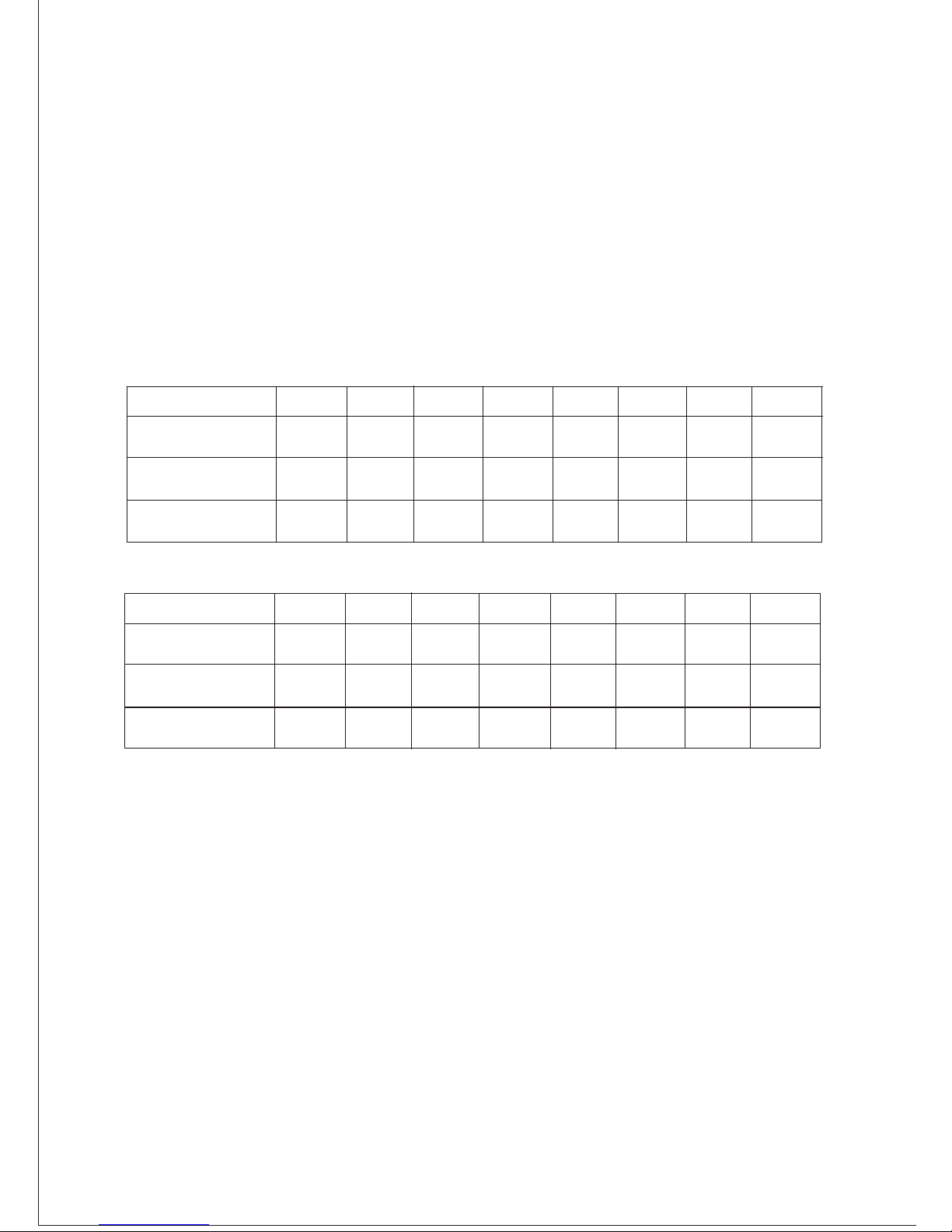
3.3 DC Output
Power distribution configuration:
+3.3V
+5V
+12V1
+12V2
-12V
+5VSB
3.0A
Model
3.4 Protection
The power supply itself is designed with short circuit, over voltage, over power
and over current protection functions described as below:
3.4.1 Short Circuit Protection
A short circuit on any DC output will cause the power to latch. The power
supply will withstand a continuous short circuit to the output without damage
or overseers to the unit. The +5V can be shorted indefinitely and will recover
SB
automatically when the short is removed.
APE-900X
25A
30A
25A
30A
18A
18A
18A
18A
18A
0.5A
+12V4+12V3
(CTG-750)
APE-1000X
(CTG-850)
18A18A
18A
0.5A
3.0A
Load range 1 (AC 115V/230V)
30A
30A
18A
+3.3V
+5V
+12V1
+12V2
-12V
+5VSB
3.0A
Model
APE-900X
30A
30A
30A
35A
18A
18A
18A
18A
18A
0.5A
+12V4+12V3
(CTG-750)
APE-1000X
(CTG-850)
18A18A
18A
0.5A
3.0A
Load range 2 (AC 230V)
APE-1100X
(CTG-1000)
APE-1100X
(CTG-1000)
30A
50A 19A 19A
19A
19A 0.5A 3.0A
30A
40A 19A
19A
19A
19A
0.5A
3.0A
3.2 Active Power Factor Correction
Active power factor correction (the advance technology most used in high power
SMPS) used a per-regulator before the main PWM convert circuit, applied the
current feedback technology. Regulated current drawing flow AC sinusoidal wave.
Therefore, the THD less than 5 percent,and the power factor increase to 0.99 or higher.
This method of PFC knows as Active Power Factor Correction because applied active
components and circuit inside. It can provide high power factor(up to 0.95-1),can
operate in world wide input range(100-240VAC).An intelligent solution for high regulation,
high power density power designs.
3.4.2 Over Voltage Protection
The power supply over voltage protection shall be locally sensed. The power
supply shall shutdown and latch off after an over voltage condition occurs. This
latch shall be cleared by toggling the PSON # signal or by an AC power
Page 4
never trip any lower than the minimum level when measured at the power pins
of the power supply connector.
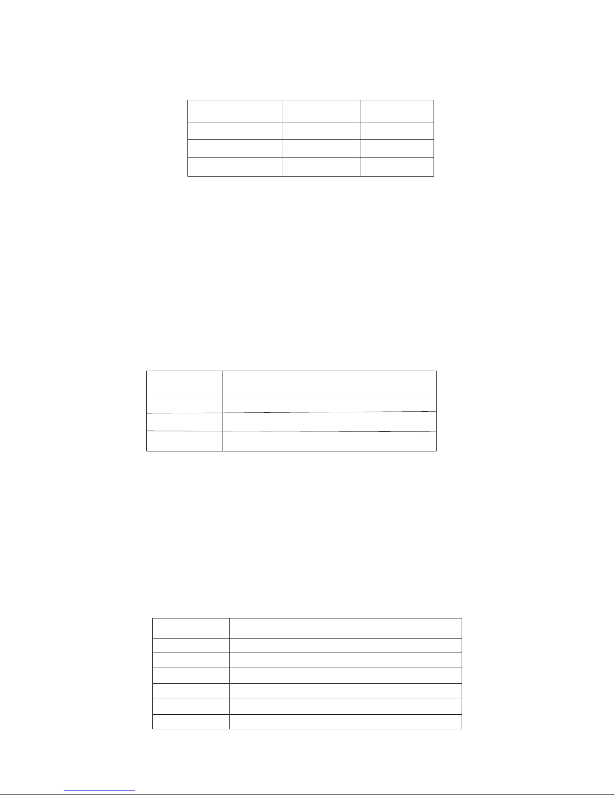
interruption. The below enclosed table contains over voltage limits. The values
are measured at the output of the connector for power supply. The voltage shall
Output Voltage
MIN(V)
MAX(V)
+3.3V
+5V
+12V1,2,3,4
3.76
5.5
13.4
4.3
7.0
15.6
3.4.3 Over Current Protection
The power supply shall have current limit to prevent the +3.3V,+5V,and +12V
outputs from exceeding the values shown in below enclosed table. If the current
limits are exceed the power supply shall shutdown and latch off. The latch will
be cleared by toggling the PSON# signal or by an AC power interruption. The
power supply shall not be damaged from repeated power cycling in this
condition.-12Vand 5VSB shall be protected under over current or shorted
conditions so that no damage can occur to the power supply. All outputs shall be
protected so that on damage occurs to the power supply under shorted output
condition.
Voltage
Over Current Limit
+3.3V
+5V
+12V
110% minimum, 150% maximum
110% minimum, 150% maximum
110% minimum, 150% maximum
3.4.4 240VA Protection
System designs may require user access to energized areas of the system. In
these cases the power supply may be required to meet regulatory 240VA energy
limits for any power rail. Since the +12V rail combined power exceeds 240VA it
must be divided into separate channels +12V rails do not necessarily need to be
independently regulated outputs. They can share a common power conversion
stage. The +12V rail is split into four rails. Refer to section 6.4 for how the 12V
rail is split between different output connectors.
Voltage
Over Current Limit
+3.3V
+5V
+12V1
+12V2
+12V3
+12V4
110% minimum, 150% maximum
110% minimum, 150% maximum
Peak current minimum, 20A maximum
Peak current minimum, 20A maximum
Peak current minimum, 20A maximum
Peak current minimum, 20A maximum
3
Page 5
3.4.5 Over Power Protection
When the total load exceed 110%~160% of the maximum output current, the
power supply shall be latched into the state of shutdown.
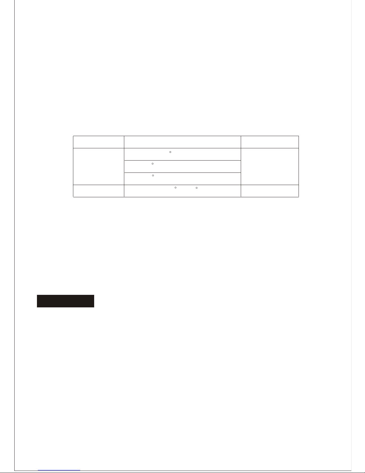
Operation Conditions
The power supply shall be capable of continuous operation and meet all
electrical specification without need for adjustment when subjected to the
following environmental conditions:
Temp. Vs Load Condition
Humidity
Operation
Storage
-20C ~80C
10% ~90%RH
5% ~90%RH
No degradation of the power supply shall occur during shipping or storage at
the specified condition.
3.6 Regulatory Compliance
Caution: Unauthorized personnel should not do this to avoid electrical
shock!
4.1 Do not open the top cover of the power supply case.
4.2 Please keep the power supply from humidity.
0 ~30C@Full Load
40C@90% Rated Load
50C@80% Rated Load
3.5 Physical Environment
4
Our power supply has been certified to comply with multi-national Safety and EMI.
TUV, UL, CUL, CSA, CE, FCC
4. Precaution
Page 6
5. Simple Maintainance
If power supply cannot work properly, before send for repair, please check the
following items:
5.1 Does power cord indeed plug into electrical outlet?
5.2 Does Input Voltage set in power supply correspond to the main source in your
environment?
5.3 Please check the output connectors plugging in proper direction and connecting
firmly.
5.4 Please turn off the power and turn it on for several times, and the interval must
be at least 5 minutes.
5.5 Having checked above items, if the power supply still does not function, please
send it back to your retailer or distributor for repair.
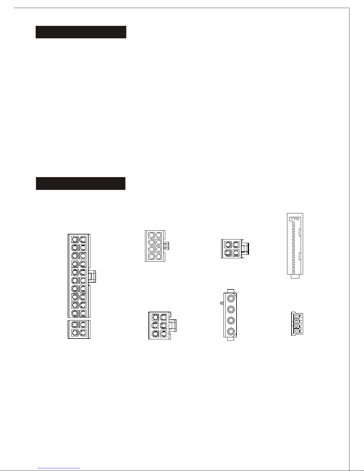
6.1 Power Connector Drawing
6. Mechanical Diagram
5
Main Power Connector
Peripheral Power
Connector
Floppy Power
Connector
+5VDC
COM
COM
+12V4DC
Pin 1
Pin 4
+12VDC
COM
COM
+5VDC
Pin 1
Pin 4
+12V Power Connector
+12VDC
+12VDC
COM
COM
Pin 3Pin 1
Pin-side view, not to scale
Serial ATA
Connector
+3.3VDC
COM
+5VDC
+12VDC
+3.3VDC
+3.3VDC
COM
COM
+5VDC
+5VDC
COM
COM
COM
+12VDC
+12VDC
Pin 1
Pin 13
+3.3VDC
COM
+5VDC
COM
+5VDC
COM
PWR_OK
+5VSB
+12V3DC
+12V3DC
+3.3VDC
-12VDC
COM
PS_ON#
COM
COM
COM
COM
N.C.
+5VDC
+5VDC
+5VDC
+3.3VDC
+3.3VDC
PCI Express
Power Connector
Pin4
+12V4DC
+12V4DC
+12V4DC
COM
COM
COM
Pin1
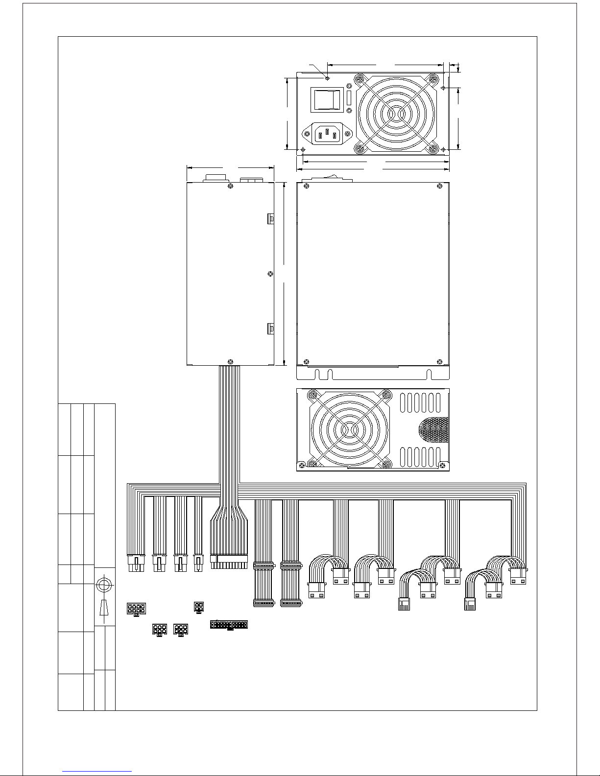
6.2 Mechanical Diagram
COM
COM
COM
COM
+12VDC
+12VDC
+12VDC
+12VDC
Processor
Power Connector
Page 7
6-#32(4x)
74.0
114.0 6
64.016.0
144.0
150.0
NOTE: The size of the Fan is 8cm.
CTG-750/850/1000
LAH
I
O
86.0
PA
Yellow/Green (+12V4DC)
Black (GND)
Black (GND)
Red (+5VDC)
PB
PC
Yellow/Green (+12V4DC)
Black (GND)
Black (GND)
Red (+5VDC)
Yellow/Green (+12V4DC)
Black (GND)
Black (GND)
Red (+5VDC)
PD
Yellow/Green (+12V4DC)
Red (+5VDC)
PE
PF
Yellow/Green (+12V4DC)
Black (GND)
Black (GND)
Red (+5VDC)
Yellow/Green (+12V4DC)
Black (GND)
Black (GND)
Red (+5VDC)
Black (GND)
Black (GND)
PG
Yellow/Green (+12V4DC)
Red (+5VDC)
PH
Yellow/Green (+12V4DC)
Black (GND)
Black (GND)
Red (+5VDC)
Black (GND)
Black (GND)
PI
Yellow/Green (+12V4DC)
Red (+5VDC)
PJ
Yellow/Green (+12V4DC)
Black (GND)
Black (GND)
Red (+5VDC)
Black (GND)
Black (GND)
Yellow/Green (+12V4DC)
Black (GND)
Red (+5VDC)
Black (GND)
Orange (+3.3VDC)
SATA
Yellow/Green (+12V4DC)
Black (GND)
Red (+5VDC)
Black (GND)
Orange (+3.3VDC)
SATA
12V 4P
Black (GND) 1
4 Yellow/Green (+12V4DC)
3 Yellow/Green (+12V4DC)
Black (GND) 2
4 Black (GND)
5 Black (GND)
6 Black (GND)
PCI-E
Yellow/Green (+12V4DC) 1
Yellow/Green (+12V4DC) 2
Yellow/Green (+12V4DC) 3
Black (GND) 1
5 Yellow/Black (+12V1DC)
8P
Black (GND) 2
Black (GND) 3
Black (GND) 4
6 Yellow/Black (+12V1DC)
7 Yellow (+12V2DC)
8 Yellow (+12V2DC)
PRELIMINARY
REV: 1
MATERIAL
TOLERANCE
DRAWN
CHECKED
APPROVED
UNIT
MM
NON
SCALE
MODEL
PART NO.
DESCRIPTION
190.0
4 Black (GND)
5 Black (GND)
6 Black (GND)
PCI-E
Yellow/Green (+12V1DC) 1
Yellow/Green (+12V1DC) 2
Yellow/Green (+12V1DC) 3
Orange (+3.3VDC) 1
Orange (+3.3VDC) 2
Black (GND) 3
Red (+5VDC) 4
Black (GND) 5
Red (+5VDC) 6
Black (GND) 7
Gray (POK) 8
Purple (+5VSB) 9
Yellow/Blue (+12V3DC) 10
Yellow/Blue (+12V3DC) 1
Orange (+3.3VDC) 2
11 Orange (+3.3VDC)
12 Blue (-12VDC)
13 Black (GND)
14 Green (PS-ON)
15 Black (GND)
16 Black (GND)
17 Black (GND)
18 N/C
19 Red (+5VDC)
20 Red (+5VDC)
4 Black (GND)
3 Red (+5VDC)
24(20+4)P
6
 Loading...