

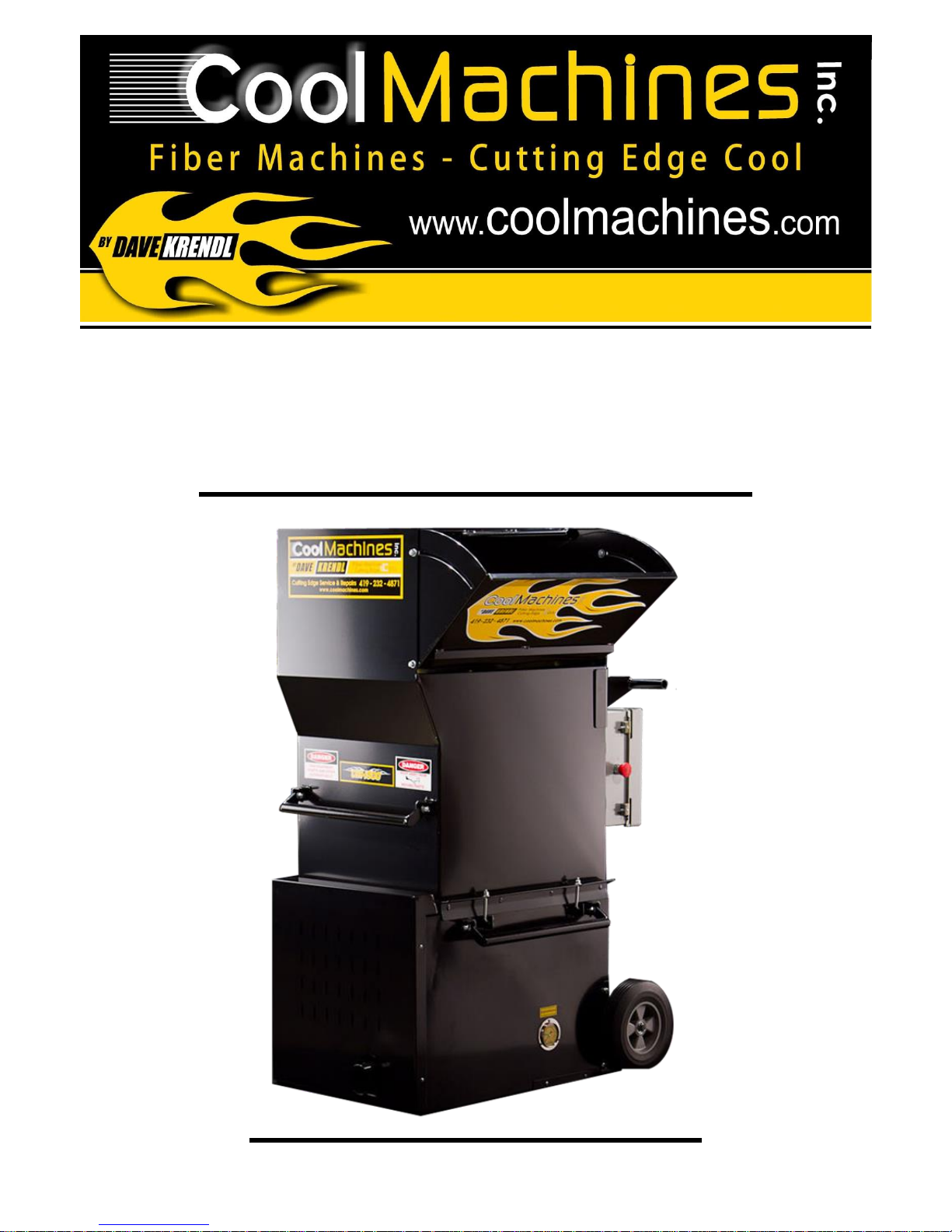
Cool Machines 1500 Series, CM-1500S Owner's Manual
740 Fox Rd., Van Wert, OH 45891
419-232-4871
CM-1500S Owner’s Manual

CM-1500S Owner’s Manual
Index:
Index……………………………..……………….……….....2
Safety / Caution…….……………………………………….3
Warranty…………….……………………………….……....4
Philosophy & Theory of Operation…………….….…..…...5
Unpacking and Machine Set-up……………………....……6
Operation and Controls……………………………....….….7
Pressure Gauge: How to Use it……………………...……11
Airlock and Seal Replacement………………………...….12
Maintenance……………………………………………..….13
Mechanical Troubleshooting…………………………....…14
Electrical Troubleshooting…………………………….…...14
Electrical Wiring Schematics……………………………...16
Parts List.…………………….……….………………….…..26
Electrical Parts List………………….…………….………..35
Rev. 12/8/2017 Page 2

Safety/Caution
Be Safe- Keep away from moving parts.
Be Safe- Make sure all guards, and hopper extensions are in proper location before operating
machine. Hands should never pass below top of main hopper.
Be Safe- Do not move machine, remove motors, or other electrical components when unit is
connected to power supply.
Be Safe- Be sure auger motor, blower motor, and remote control hand pendant are in off
position before connecting power supply to the machine.
Be Safe- Be sure machine is properly grounded. Protect all electrical supply cords from sharp
objects, moisture, and potentially hazardous materials. Keep power cords in good repair.
Electrical service must be performed by qualified electrician.
Be Safe- Disconnect power supply before inspecting or adjusting unit.
Be Safe- Consult qualified technician to answer questions before attempting to operate, or
injury may result.
Be Safe- Wear an approved dust mask or respirator for operator safety, comfort and
protection.
Be Safe- Emergency Kill Switch- In case of emergencies, always use ‘red’ stop button located
in center of main panel box. It will stop all feeding and agitation. Note: This action will not
interrupt power to the panel box.
Make Sure!!!
Hopper is empty of foreign objects before starting.
Proper electrical power is supplied or damage to unit will result.
Blower filter is kept clean and in place when blower is running.
Blower is turned off immediately if hose is plugged, or blower will overheat.
Blowers must be on when auger/airlock is running, or machine will bind.
Auger/airlock motor is not running with hopper empty for more than a few minutes, or
damage to seals will result.
Sprockets, chains, are correctly aligned and tensioned.
Pieces of bags are not left in machine as this can bind and stall machine.
Rev. 12/8/2017 Page 3

Limited Warranty
Products and components manufactured by Cool Machines Inc. are warranted to the original purchaser to be
free of defects in material and workmanship and will operate as intended for a period of two (2) years from the
date of purchase. Any product or components that do not function may be returned with proof of purchase and
(RA) return authorization to:
Cool Machines Inc.
740 Fox Road
Van Wert, Ohio 45891
Important: All items must have a Return Authorization Number attached to item for in-house tracking
purposes.
Buyer is responsible for all costs incurred in removal and reinstallation of the product and must pre-pay
shipment to the factory. Returned item will be evaluated for warranty. If warranty is approved, the product will
be replaced at no charge and returned standard ground shipping fees pre-paid. (Next day delivery and special
expediting fees is responsibility of buyer.) Note: If buyer needs immediate replacement, buyer must purchase
component and refund will be determined upon evaluation of returned part.
This limited warranty does not cover replacement of components or parts manufactured by others than
Cool Machines and become inoperative due to wear & usage and needs to be replaced on a regular basis.
Including but not limited to: airlock seals, belts, chains, auger wipers, switches, fuses, fan blades, clutches,
hoses, and filters.
Cool Machines obligation under this warranty is limited to repairing or replacing any part that is
determined by the company to be a manufacturing defect.
No warranty is made with respect to:
1. Components or accessories manufactured and warranted by others. Warranties for purchased
components supplied by vendors such as: gas engines, electric motors, blowers, gearboxes,
etc., are on file and provided upon request.
2. Defects caused by repair, alteration and/or adjustment performed by others.
3. Labor costs of repairing or replacing parts.
4. Any products not operated and/or maintained in accordance with normal industry practice
and/or written recommendations of the company.
5. Products subjected to misuse, negligence, or results of applications not in accordance with
company recommendations.
This warranty set forth above is exclusive and makes no other warranties with respect to description or
quality of the product including, but without limitation, no warranties of merchantability or fitness for a particular
purpose. This warranty set forth above does not extend to, and Cool Machines shall not be responsible for:
incidental, consequential, special or indirect damages. Cool Machines shall not be liable for penalties or any
liquidated damages.
Cool Machines shall not be liable for any injury or damage resulting from failure to follow and comply
with the instructions that accompany the product.
This warranty is expressly in lieu of all other written or oral warranties.
Return Policy: machines, accessories, and parts can be returned if un-used within a 30 day period of
purchase. All returned items are subject to a 20% re-stocking fee.
Note: warranty statement replaces previous one (1) year warranty, effective rev. 03-09-15.
Rev. 12/8/2017 Page 4

Cool Machines Philosophy:
Never build, sell, or provide a service that is not good for our customer. Placing every
customer first by exceeding expectations with high performance machines, will assure an atmosphere
for achieving our highest potential.
This manual represents information regarding the latest and greatest machine technology used
in all-fiber, all-application machine technology. (Any duplication or use of this technology may be in
violation of Cool Machines Inc. rights.)
Cool Machines Inc. provides a solution offering the highest production and lowest power
requirements. We provide compact designs with the highest quality materials; offering the highest
durability, highest corrosion resistance, easiest maintenance, and simplest troubleshooting of any
machine in its class.
Theory of Operation:
The #1500 series machine provides a proprietary ‘scalping auger’ technology, with extreme
portability and low power requirements. As different fibers are loaded into the hopper, the proprietary
‘scalping/shredder’ augers located at bottom of hopper provide a live platform for breaking and
conditioning fibers. This feature provides a positive feeding, non-bridging method of metering fibers;
offering important advantages.
First: the ‘scalping’ action of augers provides a positive feed of fibers to shredder area while
the helix configuration of the 4-blade shredder provides highly conditioned fibers for application. (A
positive feeding system will meter the fiber accurately to airlock, no-matter what angle machine is
positioned on the job site.)
Second: the low profile position of augers in relation to higher hopper sides, and moderate
speed of auger assembly reduces possibility of operator injury, while greatly extending bearing and
chain life.
Easily accessed slide-gate (located adjacent to blower filter), has an ‘adjustment pin’ for
controlling & locking-in fiber feed rate. This feature allows for quick adjustment to desired settings. As
fiber is metered thru slide-gate area, the 4-blade scalping shredder provides aggressive break-up and
blending of fibers.
Fully expanded and conditioned fiber blend enters the high production airlock (10” dia. x 14”
long airlock) and is discharged into the high pressure air stream & hose provided by a single or
optional double blower system.
Economical single blower (optional double blower), system with variable rpm blowers,
provides adequate air for most applications up to 150ft. A 5 kw generator (7.5kw, 2-blower model), or
larger can provide adequate power for both the machine.
Efficient modular component design of maintenance access areas, drive system, blower
module and control panel; offer a simple, fast method to repair your machine. Job-site down-time is
minimized.
Electrical control panel is designed with simple, easy to access & by-pass components, which
provide the operator with an instant method to troubleshoot machine’s electrical system. Control
functions are simple and easy to understand. Manual thermal overloads provide a component that is
easily re-set, reliable, and most importantly - safe.
Inherent versatility of this machine’s design provides the core element for your future upgrade
to retro-sidewall and dense packing applications. This machine is one of the basic building blocks that
allow you to transition your business without costly equipment decisions.
Rev. 12/8/2017 Page 5

Un-Packing and set-up of machine:
Machine Specifications:
Weight: Airlock: Blower/ Sizes:
CM-1500 (single blower) 310lbs. 10 ” x 10” diameter (Before S#:CM-0723 ) one or two large blowers
CM-1500 (double blower) 330lbs. 10” x 14” diameter (S#:CM-0723 -Present) one big & one small
3” output for hose
Dimensions: Power Requirements: Generator:
24” W x 37” L x 57” H Double input, 15 amp. 120 volt. 1-blower/ 5,000 watt
2 large blowers = 15 amp and 2-blower/ 7,500 watt
Hopper Capacity: 20 amp 120 volt inputs
14 cu. /ft.
What should be enclosed with your standard machine?
Machine should have a 150 ft. remote cord included inside hopper that needs to be removed and
placed on handle/cord hanger, located on control panel end of machine. All other parts and
accessories will be packaged separately and placed inside hopper for shipping.
Available Options: Wheel Assemblies, Wireless remote, Blowers (1, or 2), Internal Wetting System,
along with a complete line of hoses, fittings, couplers, hose reels, and accessories. See accessory
literature for additional offerings.
Moving and lifting machine:
(Note: hopper/control panel assembly must be detached before attempting to manually lift), otherwise
an auxiliary lifting device is needed to move this machine. The machine is designed with large flip-up
handles for convenient lifting by two people after hopper has been removed. (one on each side of
base unit). Caution: personnel with lifting restrictions should use mechanical lifting devices. The
wheel assembly is recommended for frequent moving of machine without mechanical assistance.
Locating machine in vehicle:
Machine is designed to be located on the driver’s side, rear of the vehicle. Hook-up of blowing hose
and controls are easily reached from rear of vehicle while allowing for easy adjustment and control of
machine. This provides quick access to machine service points.
Power Supply:
Depending on quantity and size of blowers, the machine will require two (2) inputs. 15 amp. and
15/20 amp.120 volt or (2 -10 amp. inputs, 240 volt, overseas) single phase power supply. If generator
is used, a 5kw (or larger depending on quantity and size of blowers), is recommended for ample
power supply. Note: providing good source of power with oversize generators & extension cords, (not
exceeding 100 ft./35 meters), will assure longevity of motors and electrical components.
Machine is shipped with short input cord(s), and connected to a male input plug(s). (except overseas
units). Consult a qualified electrician for proper recommendations on power cable size.
Machine Set-up:
After securing the machine in vehicle and hook-up of power supply has been completed, the machine
is ready for hook-up to blowing hose and remote control cord. Make sure all hose connections are
securely fastened. (Consult factory for alternative floor plan layouts of machine and equipment in
vehicle.
Rev. 12/8/2017 Page 6

Operation and Controls:
Control panel:
Control panel enclosure contains the electrical components to select (on/off) operation of motors,
control speed variations of blower(s), and protect the circuitry of main drive motor, blowers and
auxiliary devices. (If machine does not function properly, disconnect power and check manual thermal
overload breakers on front of the main panel box.)
To start machine, make sure power supply (grid/shore power or generator) is appropriate (120 or
230/240 volts overseas), and power is turned ‘on’. Check for correct voltage on panel meter (selected
models), and all switches ‘off’ position.
Note: Removable L.E.D. signal plug-ins connect power to motors located in base unit. Visually
inspect the L.E.D. lights for troubleshooting panel. If control panel fails, operator can plug power
cords directly to the motor plug-ins to by-pass control panel. For convenient factory service, the
control panel (mounted to hopper with 4 bolt fasteners), can be easily removed and returned to
factory.
Domestic Control Panel:
‘3-position’ Toggle Selector Switch.
The ‘toggle’ selector switch allows operator to control machine from the remote cord, (wireless
remote), or manually at the machine.
Remote Control: Turn switch to center ‘OFF’ position for remote cord control. Insert plug end
of remote cord into the remote receptacle located to the right of toggle switch.
Manual Control at Machine: Turn switch left to ‘air’ if operator selects blower only. (Used to
un-plug clogged fiber hose or check airlock pressure). Turn switch to ‘Feed’, if operator selects
both blower and fiber feeding mode. (Use this mode if operator has problem with remote
device and desires on/off control at the machine.)
Kill Switch E-Stop Button: Located on the left side of main panel box. Safety feature; allows for
quick shut-off of machine in case of emergency.
Auxiliary Outlets: Located on lower right side of main panel box. The 120 (230 /240 volt overseas)
‘auxiliary’ outlet (lower receptacle) has a capacity of 10 /5 amps. The upper outlet labeled ‘IWS’
provides 120 (230/240 volt overseas), 2 amp. power to turn the internal wetting system on/off with
airlock fiber feeding of machine. (Note: if amperage load in excess of two amps is used on ‘IWS’
outlet, the “panel” thermal breaker will trip on front of the panel box.)
Rev. 12/8/2017 Page 7
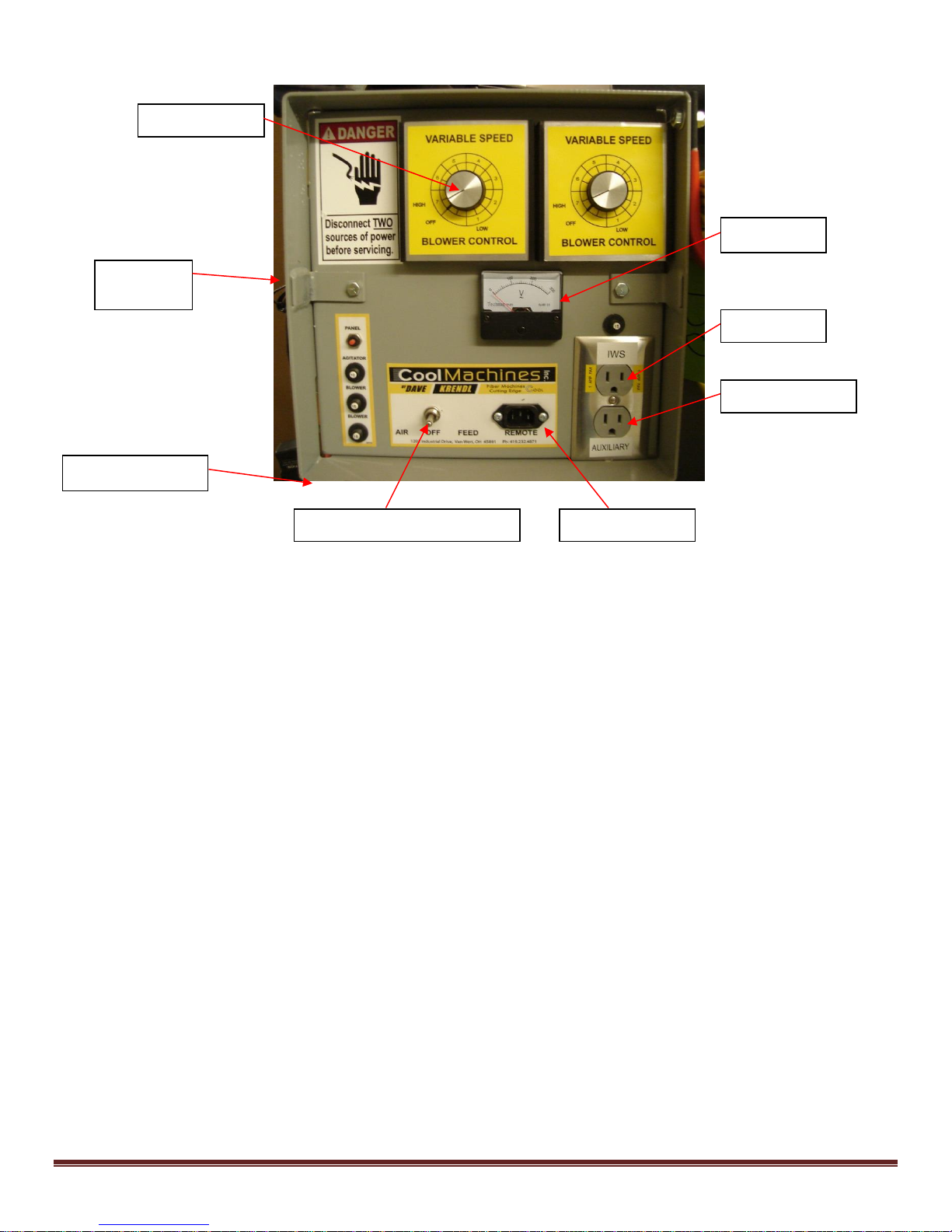
Domestic Control Panel
Blower Control
Kill Switch
(On Side)
Voltmeter
IWS Outlet
Auxiliary Outlet
‘3’- Position Selector Switch
Remote Outlet
Main Input Power
Functions of the various switches and outlets are indicated below.
Blower Control: Increase or decrease air supply to the blowing hose.
Kill Switch: Emergency stopping of the Auger and Blower motors.
Voltmeter: Visual inspection of the proper voltage.
3-position selector ‘Toggle’ switch: select manual mode (air only, off/remote, air &
material feed).
Remote Outlet: Location to plug in remote cord or wireless receiver plug.
Auxiliary Outlet: Location to plug in 110 volt accessories (10 amp. max.).
IWS outlet: Location to plug in the internal wetting system. On/Off with feed. (2 amp.
max.).
Main Input: main power feed from separate power sources. (Single, double inputs
available).
Rev. 12/8/2017 Page 8
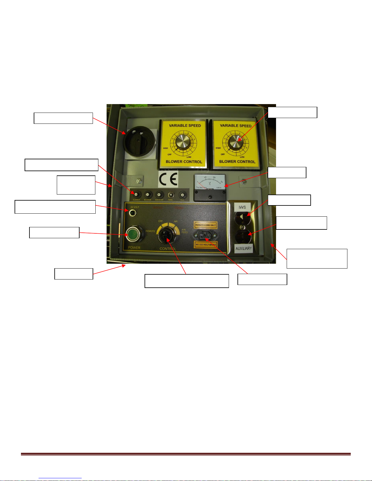
‘CE’ Overseas Control Panel:
Power Disconnect
Kill Switch
(On Side)
24 volt transformer light
Power Button
Main Input
Blower Control
Voltmeter
IWS Outlet
Auxiliary Outlet
Pre-Alarm Signal
(On Side)
4-position selector switch
Remote Outlet
Push Button Breakers
‘4-Position’ Selector Switch
Control panels for ‘CE’ specifications will have additional control features designed to conform
to European standards. These additional features include: Main panel disconnect, finger safe
connections and terminals inside panel box, 24 volt transformer power light, power drop-out button
and manual re-start relay function, 4-position selector switch, and a pre-alarm warning beeper Signal.
Auxiliary power receptacles are available in 230/240 volt for auxiliary options and accessories.
CE Overseas Control Panel
Functions of the various switches and outlets are indicated below.
Blower Control: Increase or decrease air supply to the blowing hose.
Kill Switch: Emergency stopping of the Auger and Blower motors.
Voltmeter: Visual inspection of the proper voltage.
24 volt transformer light: verifies transformer and overload breaker function. (‘CE’
overseas only)
Power Button: power interruption drop-out/ Re-start button. (‘CE’ overseas only)
4-position selector switch: select manual mode (remote, off, air only, air & material
feed). (‘CE’ overseas only)
Remote Outlet: Location to plug in remote cord.
Pre-Alarm warning signal: beeper warns operator before auger/airlock starts.
(‘CE’ overseas only).
Auxiliary Outlet: Location to plug in 230/240 volt accessories (10 amp. max.).
IWS outlet: Location to plug in the internal wetting system. On/Off with feed. (2 amp.
max.).
Main Input: main power feed from separate power sources. (Single, double inputs
available).
Rev. 12/8/2017 Page 9
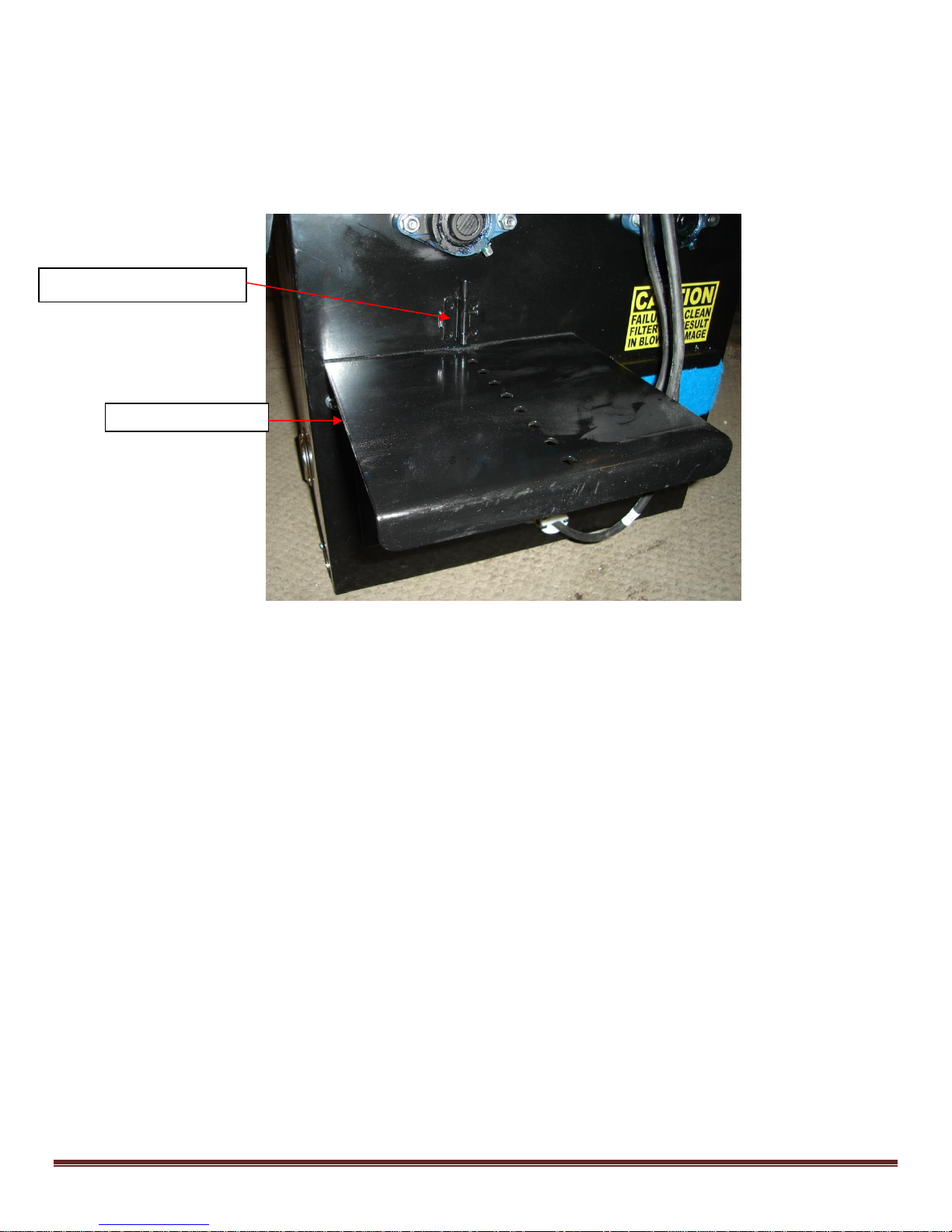
Feed gate Adjustment Pin
Feed Gate Control
Feed Gate control:
The control of fiber feed rate is adjusted with the slide gate located (under main control panel), below
the hopper area. The slide gate controls the opening to the airlock and can be adjusted with reference
to the ‘pin’ and ‘hole’ locations on the slide plate. See illustration below:
Feed Gate Settings (Approx.)
Open Blowing: high production = gate full open. (Note: if you have air setting on ‘high’ and the
velocity of fiber begins to slow at the end of the hose, ‘stop’ immediately before hose clogs and close
the gate until the correct rate of fiber feed is matched to the available air volume.)
Retrofit / drill and fill: (depending on size of hose) = 1” to 4” open.
Blower/air control:
The variable speed blower / air controls are located on the front of the main panel box. One and two
blower models: have rheostat controls that regulate the volume of air for two blowers in the blowing
hose. When turning the knobs to the left (counterclockwise), the air increases. Note: if knob is turned
past the ‘high’ setting, the blower will click to the ‘off’ mode.
Blower Adjustment with feed gate control:
Adjustment of the blower air is proportional to the feed gate setting. The higher the desired feed rate,
the higher the blower air setting. Insufficient air will result in hose plugging. As a general rule; 50%
feed gate setting will result in a 50% blower setting. However; different fibers, with moisture and
humidity conditions, may require more or less air. Once the desired feed gate setting is established,
the operator should adjust the air slightly more than desired to prevent hose plugging. Increased
blower air will increase blowing distance from the end of hose, dust, and coverage.
Rev. 12/8/2017 Page 10
Pressure Gauge: How to Use it
This machine includes a recessed pressure gauge located in the lower base unit
directly below the fold-out loading door.
The pressure gauge has two functions:
1. Calibrate air pressure for effective dense packing (cellulose) and reducing the chance of
pushing drywall from the studs.
2. Troubleshooting machine production & coverage problems and assessing wear of airlock seals
for replacement.
The performance of your machine is related to the quality of airlock seals and its ability to achieve
higher pressures. The airlock seals trap compressed air inside airlock chamber (from blowers), and
provide required air pressure & volume for optimizing you’re machines performance. When the back-
pressure drops below 3.2 p.s.i. problems will occur.
When air is leaking past the seals, this ‘blow-back’ into the hopper will cause the following
problems:
Poor quality dense packed walls allowing settling in wall cavities over a prolonged period.
Low production rates for open blow, caused by ‘blow-back’ bridging effect inside hopper.
Poor material coverage (yield) due to loss of conditioning from low air volume & pressure.
Hose plugging due to lower pushing effect of low pressure.
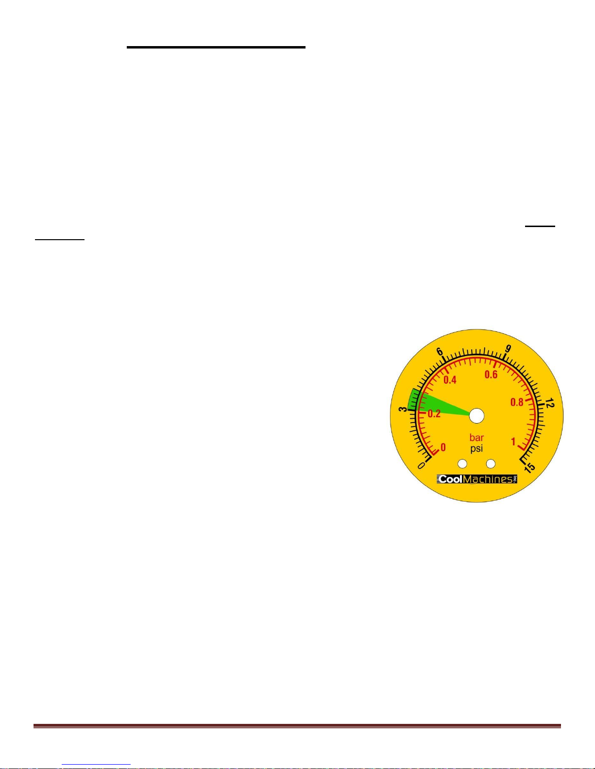
How to use:
Pressure gauge has a graduated scale (0-15 p.s.i.) with a ‘green’
colored section (3.2 p.s.i.) recommended as minimum requirement
for optimal performance.
This is the pressure recommended for effective dense packing
and acceptable machine performance for open blowing distances
over 150 ft.
Dense pack adjustment:
1. Turn blower on (no feed).
2. Back pressure system by blocking end of hose with
hand and read pressure gauge.
3. Have assistant turn blower speed up/down until the
gauge registers in green’ section of gauge (3.2 p.s.i.).
(Note: the blower control will need to be adjusted higher as airlock seals wear and lose
efficiency).
Checking airlock seals:
1. Turn blower on (no feed).
2. Back pressure system by blocking end of hose with hand and read pressure gauge.
3. Turn blower speed on high. If minimum of (3.2 p.s.i.) cannot be achieved when blowers
are adjusted on high, the airlock seals may be damaged or worn and will need to be
replaced. See page 12 of owner’s manual. (Note: longer blowing distances and higher
elevations will require higher pressure when evaluating airlock seal quality. Properly
installed ‘new’ seals, after short wear-in period, should achieve pressures over 3.5 p.s.i.)
Rev. 12/8/2017 Page 11
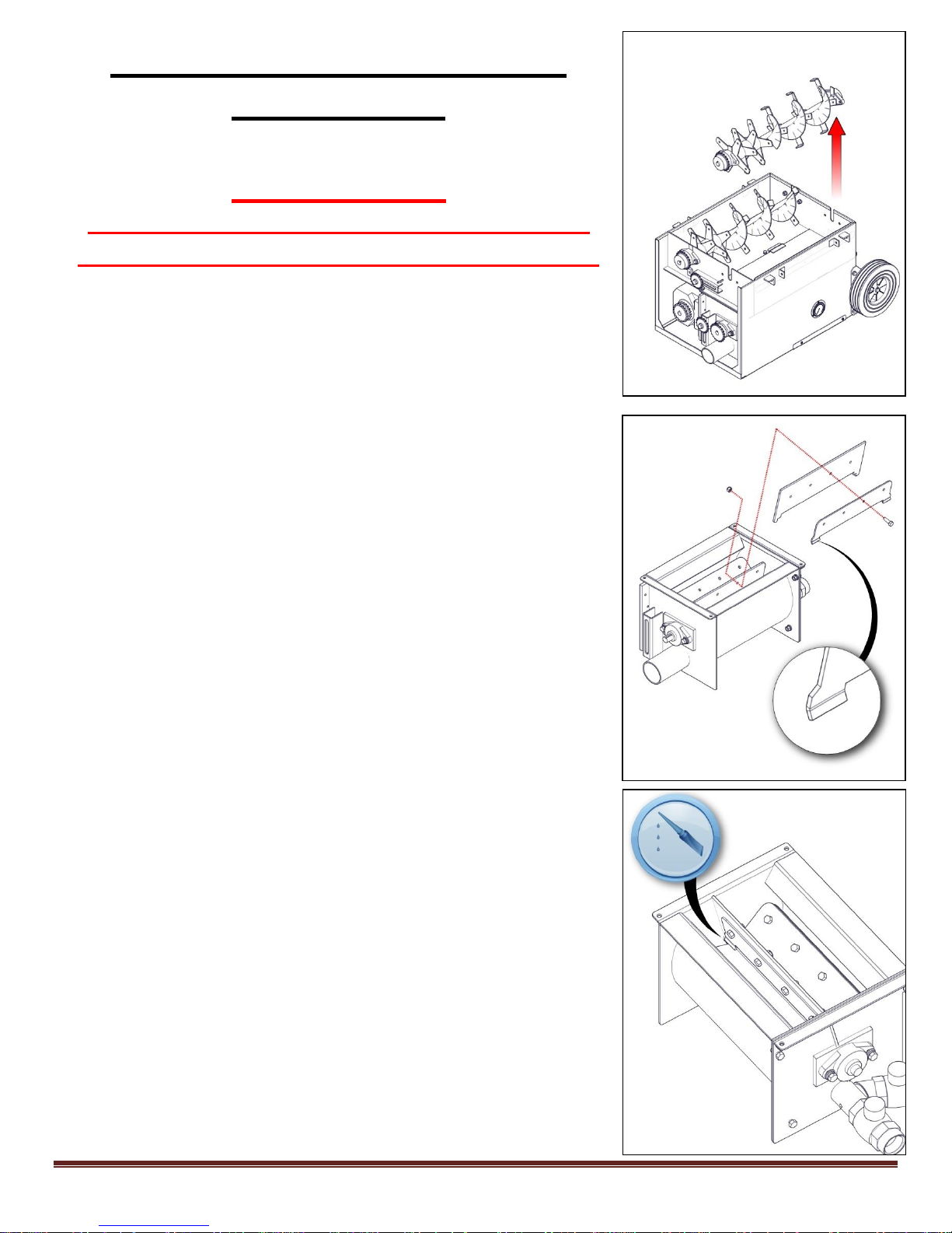
Airlock Seal Replacement
Auger Removal
Airlock Seal
Assembly
Silicone Caulk Here
Note: Top Plate
Direction
Instructions
(For CM-700 and CM-1500 models)
IMPORTANT:
Disconnect power and follow proper lock
out/tag out procedures before proceeding.
1. Remove front chain guard access panel.
2. Removed hopper from base unit.
3. Loosen chain idler sprocket located on airlock endplate, and remove chain. (If chain does not slip off,
locate and remove chain connector link.)
4. Un-bolt the bearings for the auger located directly
above the airlock.
5. Remove the auger by lifting straight up from the base.
The bearings, bearing plates, and sprocket will lift out
with the auger. See top illustration. (This will give you
access to the airlock opening so the seals can be
replaced without removing the airlock from the base.)
6. Reaching down into the airlock opening, un-bolt the
upper plate from the base plate and remove the old
seal. Remove ‘old’ silicone caulk with putty knife or flat
head screwdriver. Rotate the shaft and repeat this step
for the remaining 5 old seals. (Best Practice: Leave last
remaining seal inside chamber as example of correct
seal placement for new seals)
7. Replace with the new seals, and re-attach the upper
plates and fasteners. (Apply silicone caulk into the
shaft/endplate corner of each seal as the seals are
installed. See bottom illustration.) See middle
illustration for reassembly.
8. Tighten the bolts and lock nuts until the rubber seal
begins to distort/deform slightly. Do NOT over tighten
fasteners.
9. When installing the last paddle assembly, push the
rubber seal ‘tabs’ behind the adjacent seal with a long
flat head screwdriver.
Rev. 12/8/2017 Page 12
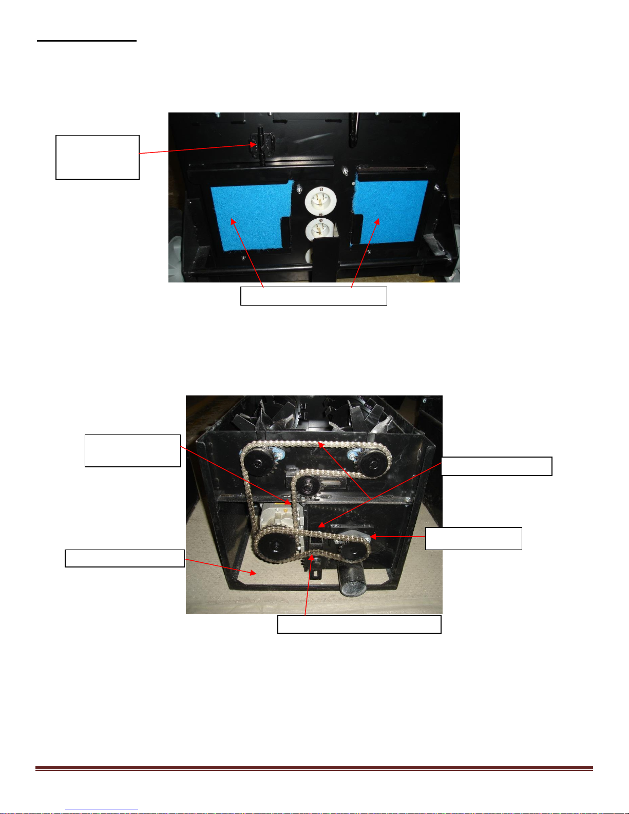
Maintenance:
Blower Filters / Keep Clean
Feed Gate
Adjustment
Pin
Check chain tension
Grease bearings
Idler Sprocket Chain Tensioner
Idler Sprocket
Chain Tensioner
Daily:
Empty fiber from machine daily.
Clean blower filter(s). Brush off exterior when not running.
(NOTE: Blower filter covers w/3” output tubes are available from factory)
Weekly:
Clean blower filter (remove and blow out with compressed air) and vacuum fiber and debris from
under machine area. (Excessive fiber build-up around motors will cause heat and prevent normal
cooling, resulting in reduced motor life.)
See illustration below: arrows to chain and idler.
Monthly:
Check airlock seals and plates for damage. (See troubleshooting: checking airlock seals)
Visually inspect and/or re-tighten all chains and sprockets.
Quarterly: (3 months)
Grease all bearings (6 total) with NLGI #2 Grease. (do not overfill, or grease seals will leak).
Rev. 12/8/2017 Page 13

Problem Corrective Action
1) Loud knocking sound
A. Check scalping augers or airlock for objects and remove.
B. Check chains for proper alignment and tension.
C. Check for bent or misaligned auger/shredder fingers.
2) Poor output or uneven flow
A. Gradually increase blower air and/or reduce fiber feed until condition improves.
B. Check hose for blockage. Clean out by turning blowers on high with feed turned off (air only). Hold hand over
output of hose, forcing pressure to increase and expand hose. Repeat this procedure several times until blockage
is removed.
C. Check all hose connections. Tighten hose clamps to eliminate air leakage.
D. Check for damaged airlock seals or bent plates inside the
airlock. Remove hopper and inspect airlock. (See previous section for replacement of airlock seals.)
3) Excessive dust /open blow
A. Reduce air into system by decreasing blower control setting and / or opening slide-gate.
B. Increase hose dia. at end of blowing hose.
C. Use an internal wetting system (IWS).
4) Cold temperature start-up
A. Turn blowers on high, while holding hand over output hose for several minutes. This will allow the airlock
chamber and seals to heat up, reducing the possibility of tripping the motor overload.
Mechanical Troubleshooting
Electrical Troubleshooting
Important!! Use proper ‘lock-out tag-out’ procedures at the main power supply before
inspecting or adjusting unit. Consult qualified electrician to answer questions before
attempting to inspect, repair, and operating; or injury may result.
Before operating machine check ‘voltmeter’ for proper voltage and pull ‘red’ kill switch
button out.
Cold temperature operation. Turn blowers on high, hold hand over output to partially
block output and create heat. After 5 minutes, airlock seals should be softening to allow startup w/o tripping reset.
1) Voltmeter indicating no or low voltage
A. Check power source for proper voltage.
B. Check input cord(s) for proper connection to power source.
C. Open Main Control Panel and check voltage with multi-tester at the voltmeter terminals. Replace if necessary.
2) Machine does not function with Remote Hand Pendant.
A. Turn machine on manually at machine with ‘toggle switch’ selector. If machine does not run, the remote cord
may be OK. Check power source.
B. Remote control cord is properly plugged in.
C. Check remote cord plug and hand pendant for damage or loose connections.
D. Check transformer breaker with continuity tester.
3) Blower motor not running, but auger motor is running.
A. Check operation with both the remote cord and manually with ’toggle’ switch on the main Panel Box.
B. Check blower speed control for ‘ON’ position.
C. Check blower breakers inside panel box.
D. Check for defective, broken, or loose wiring connections inside panel box, blower box, and at the external plug
connection.
E. Unplug external plugs centered on lower base of machine below the panel box and slide gate. Plug directly into
extension cord with 120 volt power. This will verify the blowers are OK.
F. If blower control(s) are faulty, by-pass the blower control by removing the wires at connection on back of panel
box and joining the two wires. This will offer on/off control of the blower; but blower will run full speed only.
G. Visually inspect and/or replace blower relay inside Main Control Panel.
Rev. 12/8/2017 Page 14

4) Blower motor running hot.
A. Clean or replace filter(s) located on lower base unit, below slide gate. Check intake of blowers for debris/
insulation. Blow out blower motor and surrounding area with compressed air.
B. Check blowing hose for blockage. A restriction in the output hose will cause the blowers to run hotter than
normal.
C. Check blower(s) for proper operation. (i.e. bearings, armature, excessive arcing by worn brushes.
D. Blowers have a limited life due to brush commutator wear. Blower may need replaced.
5) Excessive arcing of brushes on blower motor. (‘hissing’ or ‘scratchy’ noise)
A. Blow out brush assembly area with compressed air to remove accumulation of dirt and debris.
B. Re-seat brushes (motor repair shop). If damage to commutator is severe, replace blower.
6) Auger/Airlock motor does not run; but Blower is running.
A. Check reset breaker inside main panel box. Manual Reset on auger/airlock motor is tripped. Disconnect power
to machine. Wait until motor cools (approx. 15 minutes), Turn base unit on side and access from under machine
and press reset button on motor.
B. Check procedure for cold temperature starting above.
B. Check for defective, broken, or loose wiring connections inside main control panel.
C. Visually inspect and replace motor relay/starter inside main panel box if needed.
7) Auger/Airlock motor running improperly or hot.
A. Disconnect power. Check augers/shredders, and airlock for debris.
B. Low voltage. Check voltmeter on main panel box when machine is running. Try another electrical source. Use
proper size input cords.
C. Check bearings, chain and sprockets for problems or drive system misalignment.
D. Remove chains from motor reducer assembly. Run motor/reducer under power and check Amperage.
E. Check voltage, hertz, phase (1 phase), and direction of rotation.
F. Replace auger/airlock motor or gear motor...
8) Airlock Feeder not turning.
A. Check sprockets for missing key. Replace with 3/16” key.
B. Chain broken or slipped off sprocket. Repair or replace.
Rev. 12/8/2017 Page 15
 Loading...