

Page 1

CoolLED Commands Manual
For the pE-4000, pE-300 Series and pE-340
fura
Page 2

DOC-038 Iss 1 1
Table of Contents
1 Introduction ......................................................................................................... 2
2 Hardware .............................................................................................................. 2
2.1 TTL interface ......................................................................................................... 2
2.2 Analogue interface ............................................................................................... 2
3 Guide to CoolLED Products & Essential Commands ............................................ 3
3.1 pE-300
white
, pE-300
ultra
& pE-340
fura
...................................................................... 3
3.2 pE-4000 ................................................................................................................ 7
4 Software ............................................................................................................. 16
4.1 Setting up the USB Interface .............................................................................. 16
4.2 Control Text Strings ............................................................................................ 16
4.3 Baud Rate ........................................................................................................... 16
4.4 Synchronisation .................................................................................................. 16
4.5 pE Commands ..................................................................................................... 16
5 Full Command Set .............................................................................................. 17
Appendix A : Graphical User Interface Construction .............................................................. 24
Page 3

DOC-038 Iss 1 2
1 Introduction
This Essential Command Manual has been created to give developers the tools and
understanding to integrate CoolLED devices into third-party software. The
commands in this manual can be used to control pE-300
white
, pE-300
ultra
, pE-340
fura
and pE-4000 Illumination Systems.
2 Hardware
CoolLED systems have been designed to provide the user with a choice of ways of
controlling the LED's functions:
• Manually via switches and an intensity control on the remote ‘Control Pod’.
• From a PC using a USB virtual serial ports and software. This documentation
describes the command set required for USB control.
On the reverse panel of the CoolLED Light Source, there are connectors which
provide a choice for remote interfacing and control.
• TTL interfaces for hardware remote control (pE-300
white
, pE-300
ultra
, pE-340
fura
and
pE-4000).
• Analogue port interfaces for remote hardware control (pE-4000 only).
• USB Virtual Serial Ports (pE-300
white
, pE-300
ultra
, pE-340
fura
and pE-4000).
2.1 TTL interface
This is the simplest method for remote control of the LED arrays. There is an
individual TTL input for each physical light channel (except for the pE-300
white
which
has a single Global TTL), which when set at a high, will switch on the specific array,
overriding any manual settings on the remote pod or other remote-control signals. If
rapid switching of the LEDs is required, this is the recommended method as it is
independent of the state of the program cycle within the CoolLED Light Source.
2.2 Analogue interface
The pE-4000 Light Source offers four 0V-10V analogue inputs, with which external
equipment may control the intensity of the light output. It also offers four 0V to 10V
analogue outputs that may be used to control external equipment.
Page 4
DOC-038 Iss 1 3
3 Guide to CoolLED Products & Essential Commands
3.1 pE-300
white
, pE-300
ultra
& pE-340
fura
The pE-300
white
, pE-300
ultra
and pE-340
fura
are simple light sources to operate.
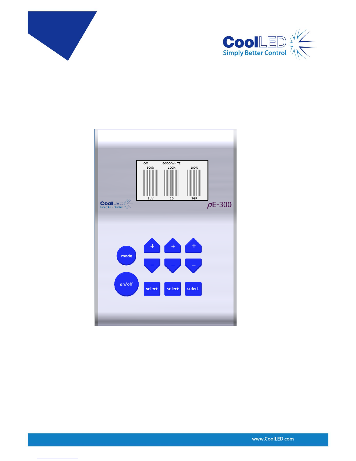
Considering the Control Pod helps explain the control options. Figure 1 shows the
Control Pod for the pE-300
white
(the pE-300
ultra
and pE-340
fura
are very similar).
As shown, the Control Pod consists of three channels that can be either selected or
deselected. The large Global on/off button when ‘on’ will switch on the selected
channels whilst leaving the deselected channels alone. When switched ‘off’ it will
switch off any selected channels that are on.
Each channel can be selected or deselected by pressing the corresponding ‘select’
button. The button marked ‘on/off’ is the Global on/off. Each channel also has its
own intensity control shown above the ‘select’ button. These buttons provide all
possible control on the pE-300
white
.
Figure 1: pE-300
white
Control Pod
Page 5
DOC-038 Iss 1 4
A TTL-In is also available through the BNC connector on the pE-300
white
and this
performs the same function as the Global on/off button but gives much more
control over precise timing. The pE-300
ultra
and pE-340
fura
also have this BNC but
additionally have individual BNC connections available to further control each
channel.
The channels are named A, B and C from left to right on the Control Pod and the
spectral regions assigned to A, B and C are in increasing wavelength with channel A
being the UV (1UV) or violet* (1V), B is the blue (2B) and channel C covers the green
through yellow to red (3GR).
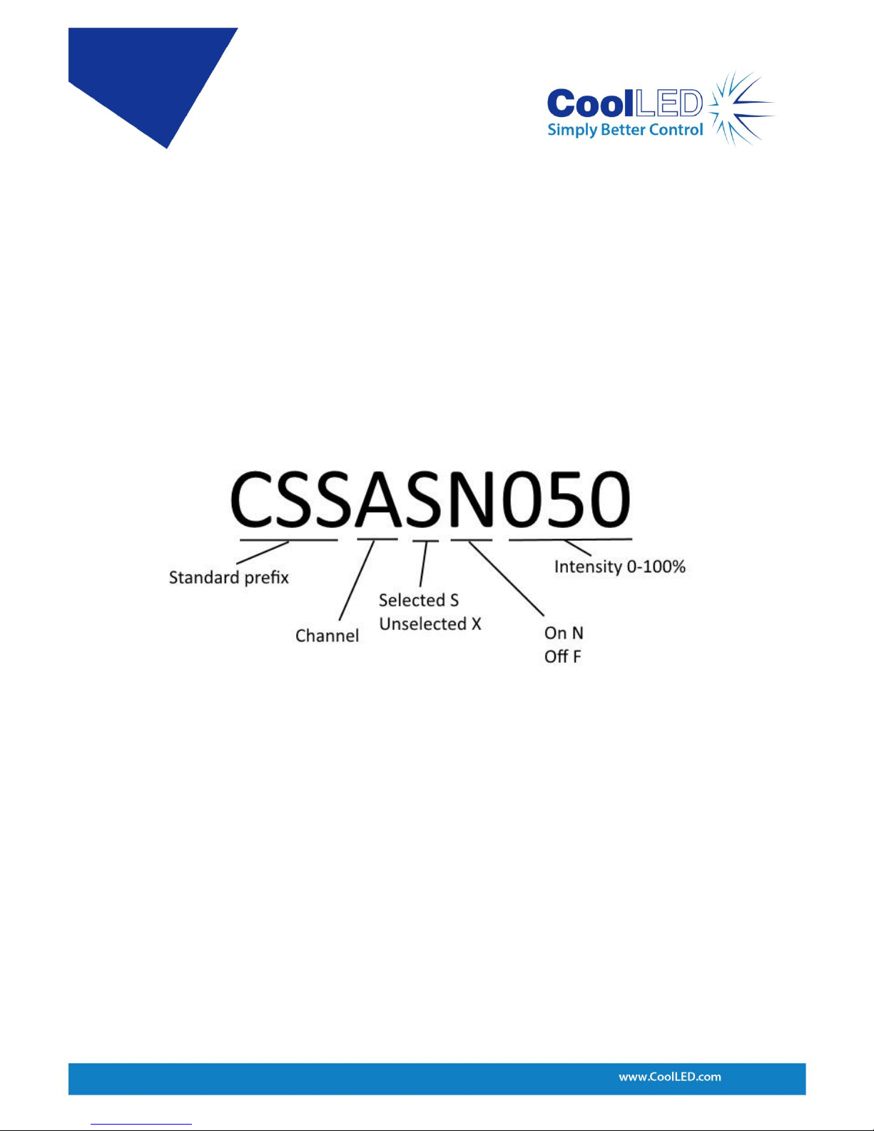
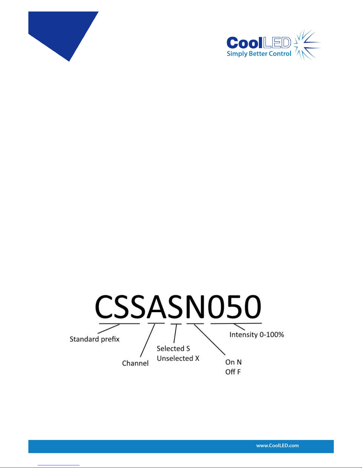
The CSS… commands can be used to select/deselect, turn on/off and also set the
intensity. This command can be used specifically for a single channel or to all three
channels together.
Examples:
• To select channel A but leave it off and set its intensity to 50% the following
command would be used: CSSASF050
• To select channel A and have it on and set its intensity to 50% the following
command could be used: CSSASN050
• To deselect channel A, which can then only be off, and have its intensity at 50% then
the command is: CSSAXF050
N.B. As a default setting the XN state is not allowed through software or Control Pod
control on the pE-300
white
and if used in a command the unit will force that channel
into the XF state.
A longer version of the CSS command can be used as shown in Figure 3:
Figure 2: CSS short command structure
Page 6

DOC-038 Iss 1 5
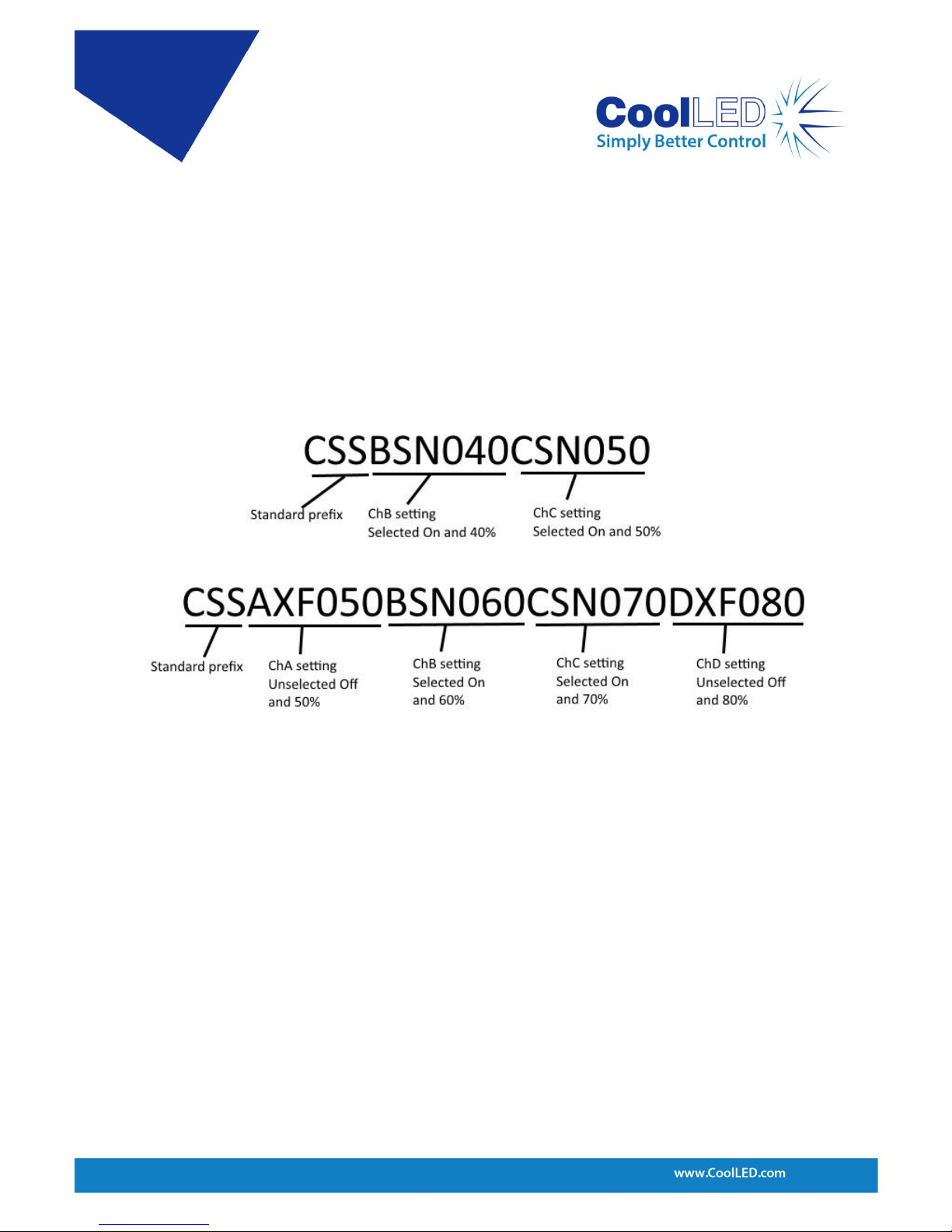
The second-long CSS command shown above sets all three channels in a single
command line. In this example ChA is set to the deselected state which is always ‘off’
and at 50% intensity. ChB is set to selected and ‘on’ and 60%, ChC is set to selected
and ‘on’ and at 70%. Notice that the intensity can be described by two or three
digits. In this example, the Global on/off button on the Control Pod will first switch
off ChB and ChC. A second press will switch on ChB and ChC. As ChA is deselected,
the Global on/off will have no effect on it.
The Global on/off commands that will switch on or switch off all selected are:
CSN All selected channels on.
CSF All selected channels off.
The Light Source channel intensities can be set individually using the short or longer
versions of the CSS command as described above. A Global intensity command is
also available which will change the intensity of all three channels but still maintain
the relative intensity between channels. This command is:
CS+ Increment intensity setting on all channels
CS- Decrement intensity setting on all channels
Figure 3: Longer CSS command structure. Not all channels need to be included in the
command and channels can be written in any order after the prefix.
Page 7

DOC-038 Iss 1 6
If the intensity settings on each channel are identical then this command will
increase or decrease the intensity of each channel by an identical amount of 1%. If
the channels are on different settings then the change will vary between channels in
order to maintain the relative balance.
As shown on the Control Pod screen in Figure 1, the wavelength labels of each
channel are displayed along the bottom of the screen under the channel intensity
bars. This information can also be acquired from the Light Source by the command:
LAMS Elicits information about the wavelengths that are available.
The status of the channels can be provided by using the command:
CSS? Elicits a response giving the status of all channels.
This will elicit a response from the Light Source in the form of the long CSS command
giving details of all channels, as shown in Figure 3.
The pE-300
white
can also be set in a mode that will provide continual reporting of the
intensity of each channel and whether it is set to on or off. The commands to set this
reporting are:
XLIVE=YES Switches on regular reporting of the status of each channel.
XLIVE=NO Switches of this regular reporting.
Information of the level of firmware and hardware of the system can be acquired by
using the following command:
XVER Elicits information about software and hardware versions.
Each command should be in upper case and terminated by a carriage return (CR),
and each response from the pE-300
white
, pE-300
ultra
and pE-340
fura
is terminated by a
carriage return and line feed (CR) (LF).
Page 8
DOC-038 Iss 1 7
3.2 pE-4000
The pE-4000 Light Source has a similar operating method to the pE-300
white
. The
Control Pod operation will be briefly covered here to explain the control but a more
detailed description can be found in the pE-4000 User Manual.
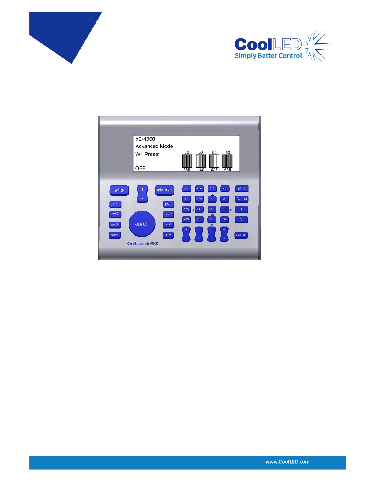
The pE-4000 Control Pod consists of two distinct regions referred to as the ‘White’
mode and ‘Advanced’ mode. When first switched on the system defaults into the
White mode and can be switched into the Advanced mode by pressing the
‘Advanced’ button. The White mode is intentionally limited in its control options and
is only available through the Control Pod. We will therefore only consider the
Advanced mode on the Control Pod when describing control options available
through software.
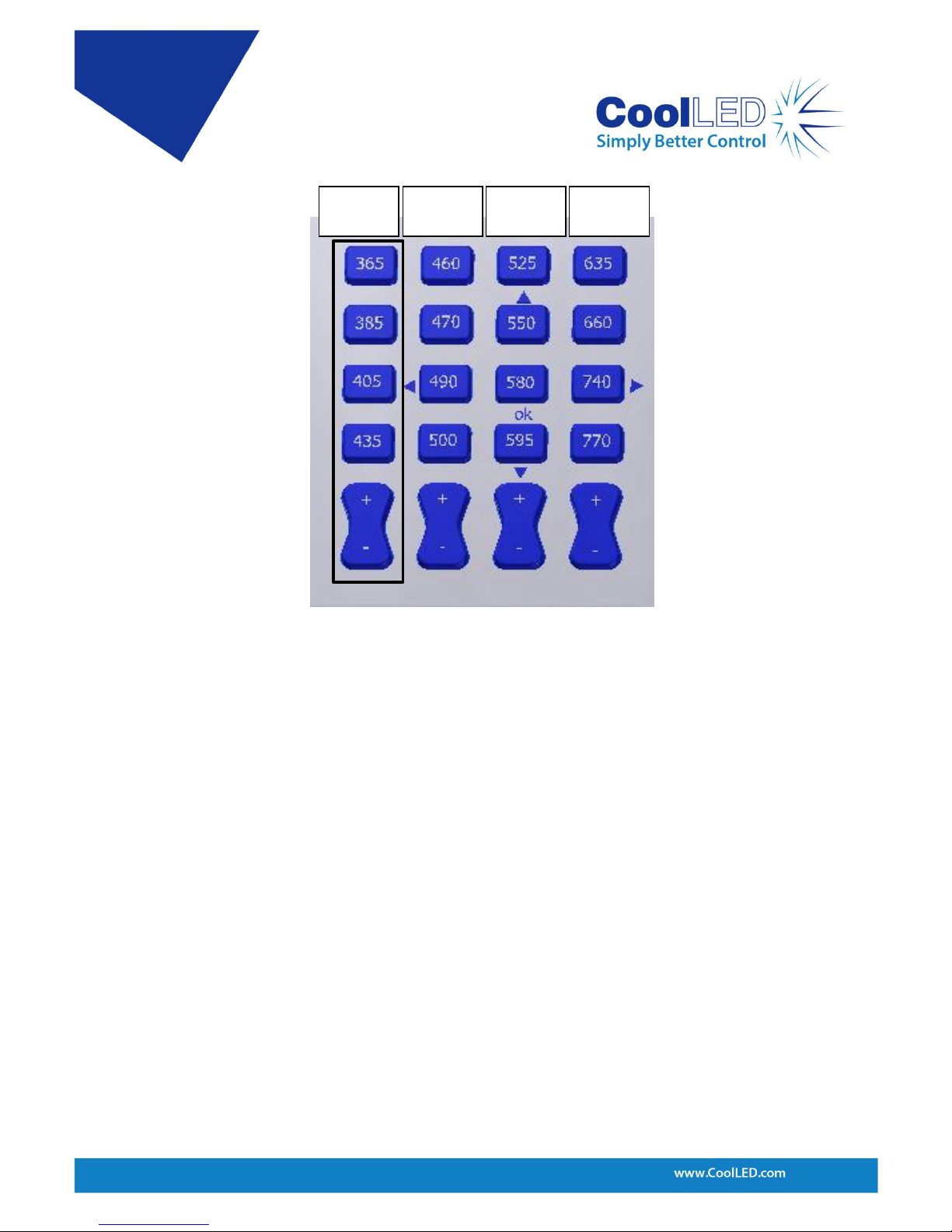
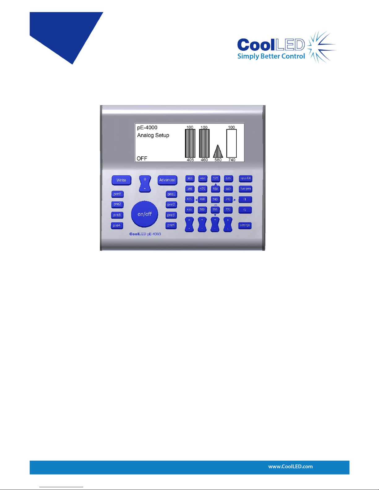
As seen on the pE-4000 Control Pod, four channels of four wavelengths each are
available with each channel aligned vertically in four columns. Channel A is the leftmost column and consists of wavelengths 365, 385, 405 and 435. The next column is
ChB, followed by ChC and ChD as shown in Figure 5.
Figure 4: pE-4000 Control Pod.
Page 9
DOC-038 Iss 1 8
Each of the four channels can have only one wavelength in use at a time. This can be
set in one of three states by software:
• Deselected
• Selected and off
• Selected and on
As a default setting, the XN state is not allowed through software or the Control Pod
on the pE-4000 and if used in a command the unit will force that channel into the XF
state.
The deselected and on state XN (SN) is an anomalous special condition state only
possible through the use of the per-channel TTL-In inputs. If a channel is deselected
and one of the per-channel TTL-In inputs goes high the wavelength in place on that
channel will switch on and into the XN state.
In this case the Global on/off button, the Global TTL In and the CSN/CSF commands
will have no effect on the channel as it is in the deselected state. Regular software or
Control Pod control can be regained over any channel in the XN state simply by
putting it into the selected state.
Figure 5: Channels A-D assigned to pE-4000 wavelengths.
Channel
A
Channel
B
Channel
C
Channel
D
Page 10

DOC-038 Iss 1 9
Just like on the pE-300
white
Control Pod ‘select’ button, alternative presses of a
wavelength button (e.g. ‘365’) will move that wavelength between the selected and
deselected state. A Global on/off button is also available on the pE-4000 Control Pod
that will with alternative presses switch on and off any selected wavelengths. The
software control commands for these functions are also identical to the commands
as described previously for the pE-300
white
, pE-300
ultra
and pE-340
fura
.
The full list of available wavelengths can be read from the pE-4000 using the
LAMBDAS command.
LAMBDAS Elicits information for all available wavelengths and their assigned
channel position.
The pE-4000 response to the LAMBDAS command is as follows; the four positions
within each channel A-D are assigned numbers 0-3:
LAMBDA:A0=365
LAMBDA:A1=385
LAMBDA:A2=405
LAMBDA:A3=435
LAMBDA:B0=460
LAMBDA:B1=470
LAMBDA:B2=490
LAMBDA:B3=500
LAMBDA:C0=525
LAMBDA:C1=550
LAMBDA:C2=580
LAMBDA:C3=595
LAMBDA:D0=635
LAMBDA:D1=660
LAMBDA:D2=740
LAMBDA:D3=770
Page 11
DOC-038 Iss 1 10
The ability to load one wavelength from a choice of four is unique to the pE-4000. In
order to load a wavelength into the ready-for-use position, the desired wavelength
only needs to have its button pressed on the Control Pod. The ‘LOAD’ command is
used to load a wavelength as follows, with 405nm being the desired wavelength in
this example.
LOAD:405 Loads 405nm into position.
The intensity of each wavelength is stored so that the intensity setting is returned
when the given wavelength is moved into the ready for use position.
The ‘LAMS’ command only responds with the wavelengths currently in the ready-foruse position along with the channel they are in.
LAMS Elicits information about the wavelength available in each channel
A typical response to the LAMS command would be as follows:
LAM:A:365
LAM:B:460
LAM:C:525
LAM:D:635
The CSS commands work on channel information and so only control the
wavelengths currently in the ready-for-use position. They can also be used to
select/deselect, turn on/off and also set the intensity. This command can be used
specifically for a single channel or for all four channels together.
Figure 6: CSS short command structure.
Page 12
DOC-038 Iss 1 11
Examples:
• To select channel B but leave it off and set its intensity to 50% the following
command would be used: CSSBSF050
• To select channel B and have it on and set its intensity to 50% the following
command could be used: CSSBSN050
• To deselect channel B, which can then only be off, and have its intensity at 50% then
the command is: CSSBXF05
A longer version of the CSS command can be used:
The second-long CSS command shown in Figure 7 sets all four channels in a single
command line. In this example, ChA is set to the deselected state which is always off
and at 50% intensity. ChB is set to selected and on and 60%, ChC is set to selected
and on and at 70% and finally ChD is set to deselected and 80%.
The status of the pE-4000 channels can be provided by using the ‘CSS?’ command.
CSS? Elicits a response giving the status of all channels.
This will elicit a response from the Light Source in the form of the long CSS command
giving details of all channels A-D, as shown in Figure 7.
In the pE-4000 condition shown in the longer form in Figure 7, the Global on/off
button on the Control Pod will first switch Off ChB and ChC. A second press will
switch On ChB and ChC. As ChA and ChD are deselected the Global on/off will have
no effect on them.
Figure 7: Longer CSS command structure. Not all channels need to be included in the command and
channels can be arranged in any order after the CSS prefix.
Page 13

DOC-038 Iss 1 12
The pE-4000 can also be set into a mode that will provide continual reporting of the
intensity of each channel and whether it is set to on or off. The ‘XLIVE’ command
provides this function.
XLIVE=YES Switches on regular reporting of the status of each channel.
XLIVE=NO Switches of this regular reporting.
The Global on/off commands that will switch on or switch off all selected are:
CSN Sets all selected channels to on.
CSF Sets all selected channels to off.
The Light Source channel intensities can be set individually using the short or longer
versions of the CSS command as described above. There is a Global intensity button
on the pE-4000 that will change the intensity of all four channels simultaneously but
still maintain the relative intensity between channels. The command for this is:
CS+ Increment intensity setting on all channels.
CS- Decrement intensity setting on all channels.
If the intensity settings on each channel are identical then this command will
increase or decrease the intensity of each channel by an identical amount of 1%. If
the channels are on different settings then the change will vary between channels in
order to maintain the relative balance.
Information of the pE-4000 level of firmware and hardware can be acquired by using
the following command:
XVER Elicits information about software and hardware versions.
This information can also be seen on the Control Pod screen by pressing the
‘settings’ button when in the Advanced mode then using the Global intensity control
‘+’ to move into the ‘Information 1’ screen.
The pE-4000 has the ability to accept 4 analogue input signals, each one
corresponding to one of the four channels A-D. The analogue signal voltage of
between 0-10V will be translated by the pE-4000 into an intensity setting of between
0-100% on the corresponding channel. The pE-4000 system must first have the
channels that are intended to work in this analogue format set into the analogue
mode. This can be done using the Control Pod by first pressing the F1 button and
then pressing the wavelength that is wanted to operate in the analogue mode.
Pressing the same wavelength button again will deselect it from the analogue mode
while the F1 button is still active. When the F1 button is active it will be backlit. To
stop wavelengths responding to the analogue function in this way F1 should be
deselected by pressing it again, so that its backlight goes off.
Page 14
DOC-038 Iss 1 13
When a wavelength is set into the analogue mode, the intensity bar on the Control
Pod screen will turn into a curve shaped icon used to represent analogue mode (see
below).
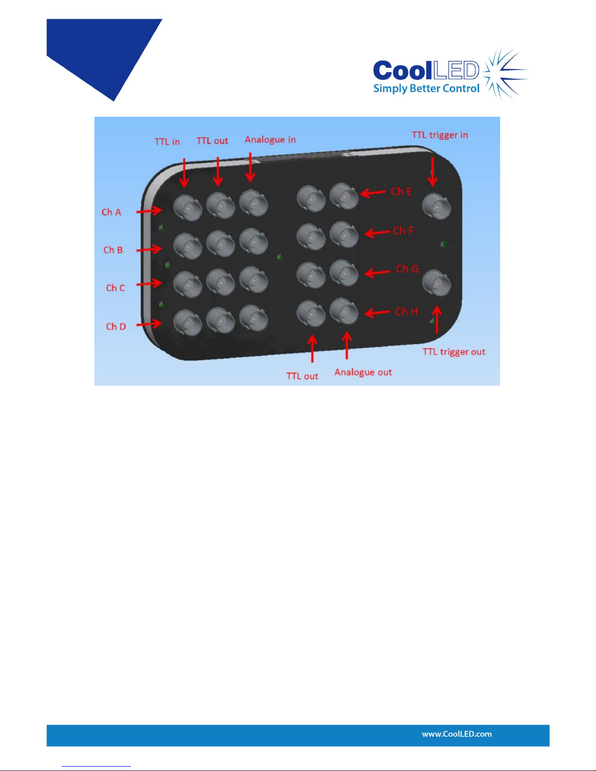
The analogue inputs can be seen clearly on the pE-Expansion Box that is commonly
used to interface with the 25 pin D-Type connector as shown in Figure 9.
Through software control the current wavelength on a channel can be set into
analogue mode by the ‘ANxN’ command. In this example, the current ready-for-use
wavelength on ChC is set into analogue mode:
ANCN Sets current wavelength on channel C into analogue mode, primed for input.
ANCF Sets the current wavelength on channel C out of the analogue mode.
Figure 8: The 580nm wavelength is set into the Analogue mode.
Page 15
DOC-038 Iss 1 14
As can be seen in Figure 9 the pE-Expansion Box shows TTL and Analogue outputs for
4 channels E-H. These outputs are available for controlling peripheral devices such as
a pE-100. The TTL out high/low can be seen as an on/off and the voltage that is put
onto the Analogue out of 0-10V can be considered as an intensity of 0-100%.
Considering the outputs in this form explains the control approach which is similar to
that used on channels A-D.
Figure 9: Expansion Box that fits onto the 25-way D-Type connector on the pE-4000.
Page 16
DOC-038 Iss 1 15
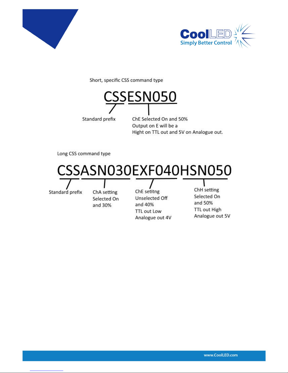
CSS commands can be used to control the outputs on Channels E-H. The command
can be used in its short or long form as shown in Figure 10:
If desirable, the Control Pod can be locked out during software operation. This
feature can reduce the risk of an experiment or routine being accidently interrupted
by a Control Pod button press. The ‘PORT:P’ commands are used to control this. The
‘P’ stands for Control Pod.
PORT:P=OFF Disables all Control Pod inputs.
PORT:P=ON Re-enables the Control Pod inputs.
Each command should be in upper case and terminated by a carriage return (CR).
Each response from the pE-4000 is terminated by a carriage return (CR) and line feed
(LF).
Figure 10: CSS commands that address output channels E-H.
Page 17

DOC-038 Iss 1 16
4 Software
4.1 Setting up the USB Interface
The USB interface is it is compatible with all versions of Windows from Windows XP
onwards via its use of Microsoft’s own built-in drivers for Virtual Serial Ports. This
means that CoolLED devices behave very much as an ordinary COM port on your
Windows PC and can be controlled by any application that uses COM ports correctly.
While this means that no special drivers are required, there is a requirement to tell
Windows about our hardware via ‘.INF’ driver file. This is a file named ‘CoolLED-
pE.inf’ and is available from the CoolLED website:
https://www.coolled.com/wp-content/uploads/2018/05/coolled-driver.zipip
When you first plug the pE system into your PC via the USB interface, Windows will
tell you it has found new hardware. It will ask you for the location of the driver file.
Point Windows to the location where you saved the .inf file.
4.2 Control Text Strings
The base interface between a controlling computer and pE is a simple set of text
commands and responses usually sent via a USB ‘Virtual Serial Port’ interface. These
command strings are typically a few characters long, comprising of standard ASCII
characters which are always terminated by an end of line character, either <cr>
or<lf>. Commands are not case-sensitive but for simplicity and consistency in this
manual capitalisation is used.
4.3 Baud Rate
The recommended baud rate for the pE-300
white
, pE-300
ultra
, pE-340
fura
and pE-4000 is
57600.
4.4 Synchronisation
It is important to note that the logic of CoolLED systems is to execute one command
line at a time; the device will only send a response after its given action has been
completed. The device will not action any further commands until the response is
given.
4.5 pE Commands
The CSS command and response have the form: CSS[xsn]. The letter ‘x’ defines the
channel (A to H), ‘s’ refers to S (Selected) or X (Not selected), ‘n’ refers to N (On) or F
(Off) and ‘nnn’ is the intensity in integer percent. The response will always be
alphabetic order, but may use more or fewer channels (the pE-4000 offers additional
channels E to H for TTL + Analogue outputs, where On/Off controls the TTL and
intensity controls the analogue output).
Page 18
DOC-038 Iss 1 17
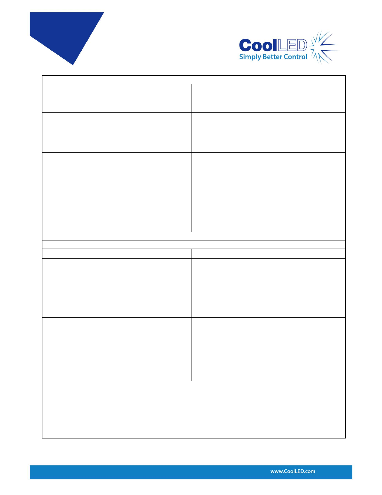
5 Full Command Set
Command:
CSS?
Description:
Elicits a status map response for all channels.
pE-300
white
pE-300
ultra
& pE-340
fura
Example Response:
CSSAXF050BSF050CSF050CRLF
pE-4000 Example Response
CSSAXF050BSF050CSF050DSF050CRLF
Command:
CSS. . . . . .
Description:
Sets channel intensities.
e.g. CSSASN10BSF20CXF30
pE-300
white
pE-300
ultra
& pE-340
fura
Example Response:
CSSASN10BSF20CXF30CRLF
pE-4000 Example Response:
CSSASN10BSF20CXF30DSN40CRLF
Command:
LAMBDAS
Description:
LAMBDA enquiry:
Elicits information about the wavelengths available.
pE-300
white
& pE-300
ultra
Example Response:
LAMBDA:A0:1UVCRLF
LAMBDA:B0:2BCRLF
LAMBDA:C0:3GRCRLF
pE-340
fura
Example Response
LAMBDA:A0:340CRLF
LAMBDA:B0:380CRLF
LAMBDA:C0:3WTCRLF
Page 19
DOC-038 Iss 1 18
pE-4000 Example Response:
LAMBDA:A0=365CRLF
LAMBDA:A1=385CRLF
LAMBDA:A2=405CRLF
LAMBDA:A3=435CRLF
LAMBDA:B0=460CRLF
LAMBDA:B1=470CRLF
LAMBDA:B2=490CRLF
LAMBDA:B3=500CRLF
LAMBDA:C0=525CRLF
LAMBDA:C1=550CRLF
LAMBDA:C2=580CRLF
LAMBDA:C3=595CRLF
LAMBDA:D0=635CRLF
LAMBDA:D1=660CRLF
LAMBDA:D2=740CRLF
LAMBDA:D3=770CRLF
Command:
LAMS
Description:
LAM enquiry:
Elicits information about the wavelengths ready for use.
pE-300
white
& pE-300
ultra
Example Response:
LAM:A:1UVCRLF
LAM:B:2BCRLF
LAM:C:3GRCRLF
LAM:D:----CRLF
Page 20
DOC-038 Iss 1 19
pE-340
fura
Example Response
LAM:A:340
LAM:B:380
LAM:C:WHT
LAM:D:----
pE-4000 Example Response:
LAM:A:365CRLF
LAM:B:460CRLF
LAM:C:525CRLF
LAM:D:635CRLF
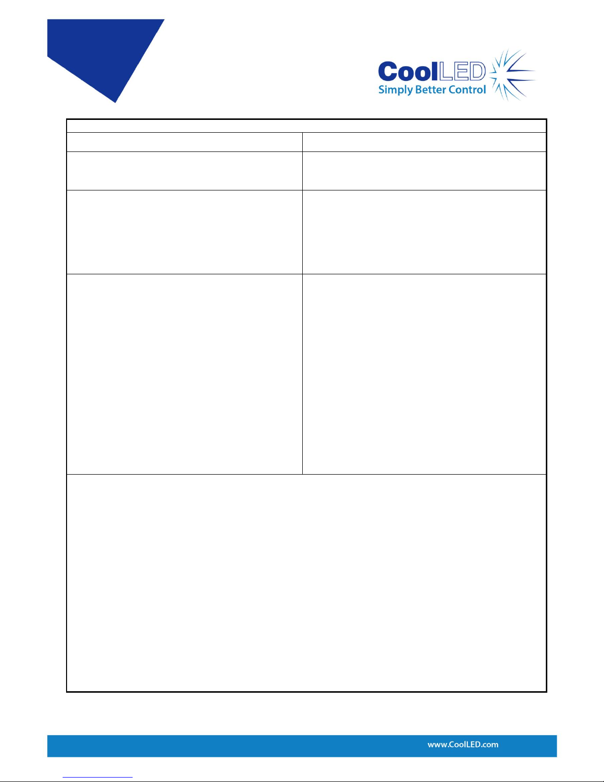
Command:
LOAD: NNN
Description:
Asks a pE-4000 to load an LED. E.g LOAD:470
pE-300
white
pE-300
ultra
& pE-340
fura
Example Response:
N/A
pE-4000 Example Response:
(2 responses are given: one is a channel status
response and the other is the loaded LAM response)
CB050FCRLF
LAM:B:470CRLF
Command:
ANxN & ANxF
Description:
Switches analogue control input on or off on the current
wavelength on specified channel. e.g. ANAN puts
channel A into analogue mode, whilst ANAF switches it
off.
pE-300
white
pE-300
ultra
& pE-340
fura
Example Response
to ANAN:
ANANCRLF
pE-300
white
pE-300
ultra
& pE-340
fura
Example Response:
ANAF:
ANAFCRLF
pE-4000 Example Response to ANAN:
ANANCRLF
pE-4000 Example Response to ANAF:
ANAFCRLF
Page 21
DOC-038 Iss 1 20
Command:
CSn
Description:
Similarly to the Global TTL input, this switches on or off
selected channels. E.g. CSN, CSF
pE-300
white
pE-300
ultra
& pE-340
fura
Example Response:
(Channels A & B are selected)
CA010NCRLF
CB020NCRLF
CSSASN010BSN020CXF030CRLF
pE-4000 Example Response:
(Channels A, B, C & D are selected)
CA050NCRLF
CB050NCRLF
CC050NCRLF
CD050NCRLF
CSSASN050BSN050CSN050DSN050CRLF
Command:
C[+-]
Description:
Changes intensity of all channels in Global increments
and decrements. E.g. CS+
pE-300
white
pE-300
ultra
& pE-340
fura
Example Response:
(All channels at 20, CS+ command issued)
CA021FCRLF
CB021FCRLF
CC021FCRLF
pE-4000 Example Response:
(All channels at 50, CS+ command issued)
CA051FCRLF
CB051FCRLF
CC051FCRLF
CD051FCRLF
Page 22
DOC-038 Iss 1 21
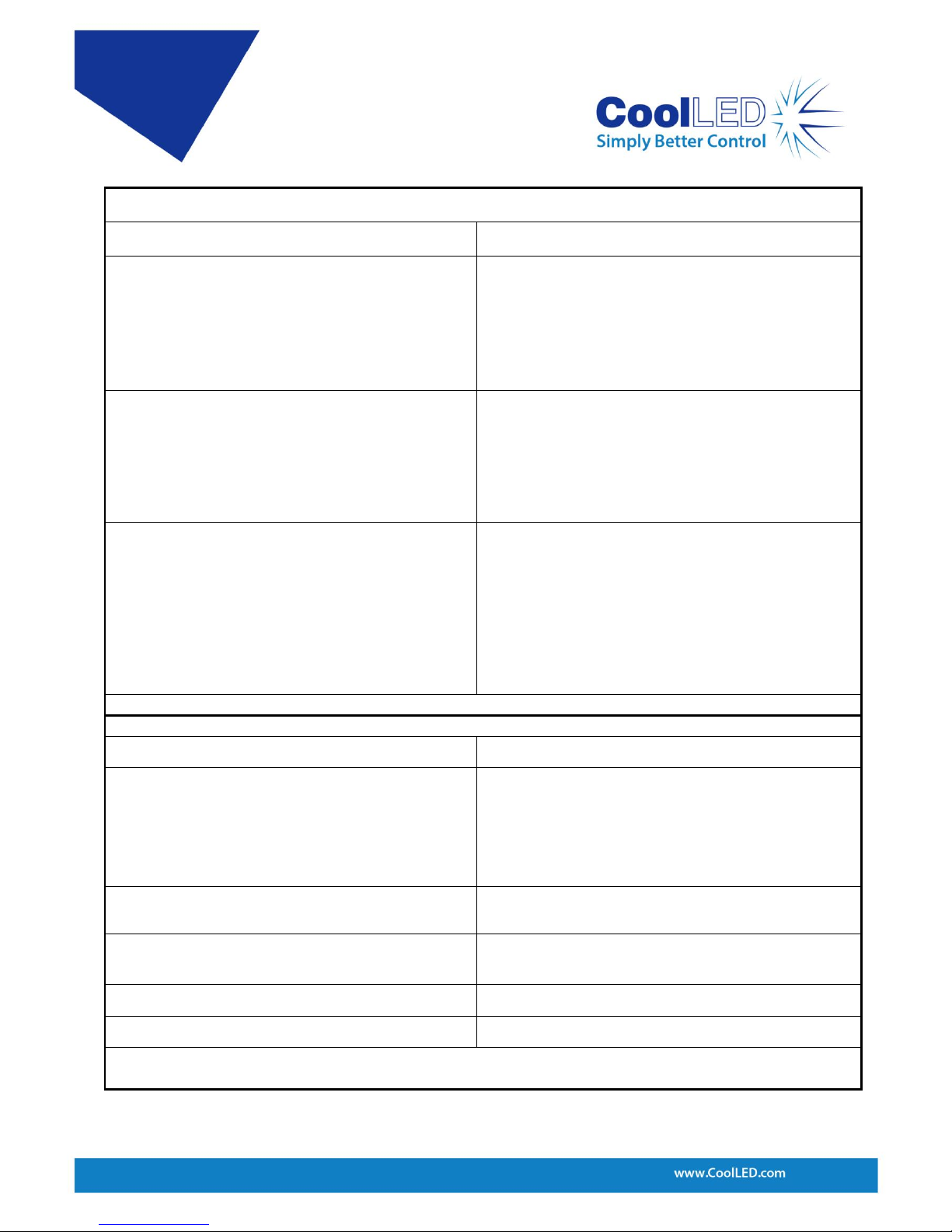
Command:
XVER
Description:
Version enquiry:
Elicits various information about the software and
hardware versions
pE-300
white
pE-300
ultra
& pE-340
fura
Example Response:
XFW_VER=2.2.9CRLF
XHW_VER=1CRLF
XDATA_VER=1.0CRLF
XPOD_FW=2.0.0 CRLF
pE-4000 Example Response:
XFW_VER=2.0.14CRLF
XHW_VER=1CRLF
XDATA_VER=1.0CRLF
XPOD_FW=2.0.1CRLF
XFW_BAK:A=2.0.3CRLF
XFW_BAK:B=2.0.3CRLF
XFW_BAK:C=2.0.3CRLF
XFW_BAK:D=2.0.3CRLF
Page 23
DOC-038 Iss 1 22
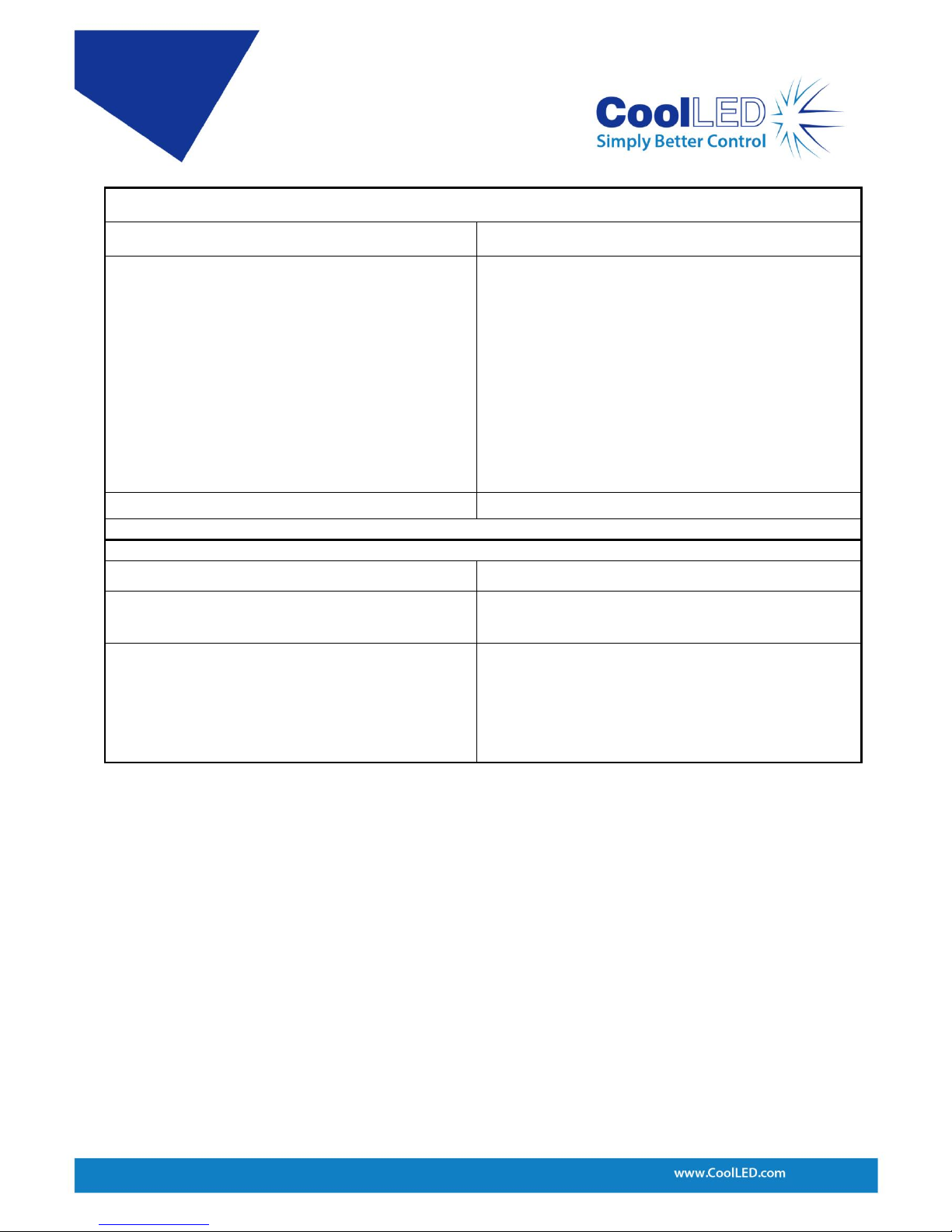
Command:
XLIVE
Description:
Channel Reporting:
XLIVE=YES: Reports channel state regularly at 10 second
intervals.
XLIVE=NO: Reports only as a response to channel
commands.
pE-300
white
pE-300
ultra
& pE-340
fura
Example Response:
XLIVE=YESCRLF
CA010FCRLF
CB020FCRLF
CC030FCRLF
pE-4000 Example Response:
XLIVE=YESCRLF
CA010FCRLF
CB020FCRLF
CC030FCRLF
CD040FCRLF
Command:
PORT:P=
Description:
Control Pod Toggling:
PORT:P=ON: Pod control is enabled
PORT:P=OFF: Pod control is disabled
pE-300
white
pE-300
ultra
& pE-340
fura
Example Response
to PORT:P=ON:
PORT:P=ONCRLF
pE-300
white
pE-300
ultra
& pE-340
fura
Example Response
to PORT:P=OFF:
PORT:P=OFFCRLF
pE-4000 Example Response to PORT:P=ON:
PORT:P=ONCRLF
pE-4000 Example Response to PORT:P=OFF:
PORT:P=OFFCRLF
Page 24
DOC-038 Iss 1 23
Command:
SEQA[0-3]:nnnB[0-3]:nnnC[0-3]:nnn
Description:
Sequence Runner Control (pE-300
ultra
& pE-340
fura
only):
This steps through a preset sequence on the Global TTL
on the rising edge.
Where nnn denotes the channel intensity, 0-3 is
sequence number, 0 means the channel is unselected
e.g. SEQA2:050B0:033C1:080
To stop the sequence runner, send any valid CSS
standard command
pE-300
ultra
& pE-340
fura
Example Response:
CRLFQA2:050B0:033C1:080CR
Command:
SEQ?
Description:
Sequence Enquiry
(pE-300
ultra
& pE-340
fura
only)
pE-300
ultra
& pE-340
fura
Example Response:
SEQ:A2:050CRLF
SEQ:B0:033CRLF
SEQ:C1:080CRLF
Page 25

DOC-038 Iss 1 24
Appendix A: Graphical User Interface Construction
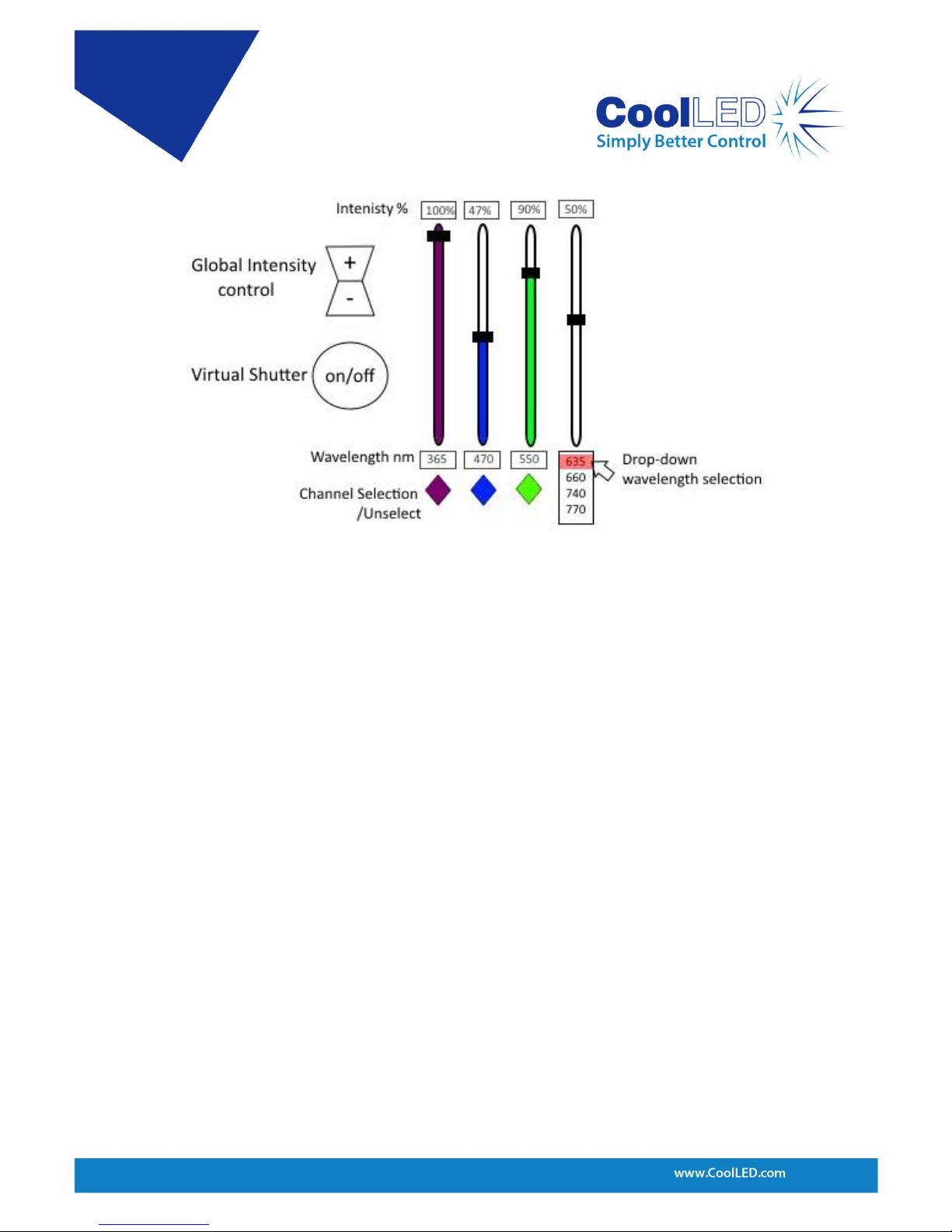
The fundamental controls necessary for an LED system can be covered by four
simple control functions as are listed below. Some suggestions of how a GUI may be
designed are given only to provide some assistance if needed.
a) The ability to read in and load available wavelengths on the GUI.
• The ‘LAMS’ command on the pE-4000 is used to read the ready for use wavelengths
but also to read in the fixed wavelength descriptions on the pE-300
white
.
• The ‘LAMBDAS’ command on the pE-4000 allows all available wavelengths to be read
in and possibly displayed in a drop-down menu or list as shown in Figure 11.
• ‘LOAD:xxx’ command on the pE-4000. Loading wavelengths may be achieved by
clicking on the desired wavelength through a drop-down menu or list.
b) The ability to set the intensity of each channel.
• The CSS commands allow the intensity to be set independently for each channel.
This could be provided as a slider mechanism in the GUI or as a box where intensity
can be set directly, or as both. This can be seen in Figure 11.
• The CS+ and CS- commands can also be used as a Global intensity control if desired.
c) The ability to select or deselect the wavelengths that are ready for use.
• The short or long CSS command may be used for the purpose of setting the channel
state into ‘XF’ or ‘SF’. The ability to select only the wavelengths of interest means
that unneeded wavelengths can be left off when using a Global on/off control.
d) The ability to switch on and off the desired wavelengths.
• The CSS commands can do this for each channel independently, e.g. CSSASN100.
This could be incorporated as a checkbox for each channel.
• The CSN and CSF commands can be used as a Global on/off for selected channels.
This command may be considered as a shutter and exist as a separate button.
Page 26
DOC-038 Iss 1 25
Figure 11 shows a mixture of GUI controls that may be applied to the control of the
pE-4000 or pE-300
white
. This is only covering the most basic control but the designer
may include other functions, for example the analogue mode option and control for
the extra channels E-H.
Figure 11: Example of a GUI.
 Loading...