

CoolLED pE-300white, pE-4000 Illumination Systems, pE-300ultra, pE-340fura Command Manual

CoolLED Commands Manual
For the pE-4000, pE-300 Series and pE-340
fura

DOC-038 Iss 1 1
Table of Contents
1 Introduction ......................................................................................................... 2
2 Hardware .............................................................................................................. 2
2.1 TTL interface ......................................................................................................... 2
2.2 Analogue interface ............................................................................................... 2
3 Guide to CoolLED Products & Essential Commands ............................................ 3
3.1 pE-300
white
, pE-300
ultra
& pE-340
fura
...................................................................... 3
3.2 pE-4000 ................................................................................................................ 7
4 Software ............................................................................................................. 16
4.1 Setting up the USB Interface .............................................................................. 16
4.2 Control Text Strings ............................................................................................ 16
4.3 Baud Rate ........................................................................................................... 16
4.4 Synchronisation .................................................................................................. 16
4.5 pE Commands ..................................................................................................... 16
5 Full Command Set .............................................................................................. 17
Appendix A : Graphical User Interface Construction .............................................................. 24

DOC-038 Iss 1 2
1 Introduction
This Essential Command Manual has been created to give developers the tools and
understanding to integrate CoolLED devices into third-party software. The
commands in this manual can be used to control pE-300
white
, pE-300
ultra
, pE-340
fura
and pE-4000 Illumination Systems.
2 Hardware
CoolLED systems have been designed to provide the user with a choice of ways of
controlling the LED's functions:
• Manually via switches and an intensity control on the remote ‘Control Pod’.
• From a PC using a USB virtual serial ports and software. This documentation
describes the command set required for USB control.
On the reverse panel of the CoolLED Light Source, there are connectors which
provide a choice for remote interfacing and control.
• TTL interfaces for hardware remote control (pE-300
white
, pE-300
ultra
, pE-340
fura
and
pE-4000).
• Analogue port interfaces for remote hardware control (pE-4000 only).
• USB Virtual Serial Ports (pE-300
white
, pE-300
ultra
, pE-340
fura
and pE-4000).
2.1 TTL interface
This is the simplest method for remote control of the LED arrays. There is an
individual TTL input for each physical light channel (except for the pE-300
white
which
has a single Global TTL), which when set at a high, will switch on the specific array,
overriding any manual settings on the remote pod or other remote-control signals. If
rapid switching of the LEDs is required, this is the recommended method as it is
independent of the state of the program cycle within the CoolLED Light Source.
2.2 Analogue interface
The pE-4000 Light Source offers four 0V-10V analogue inputs, with which external
equipment may control the intensity of the light output. It also offers four 0V to 10V
analogue outputs that may be used to control external equipment.
DOC-038 Iss 1 3
3 Guide to CoolLED Products & Essential Commands
3.1 pE-300
white
, pE-300
ultra
& pE-340
fura
The pE-300
white
, pE-300
ultra
and pE-340
fura
are simple light sources to operate.
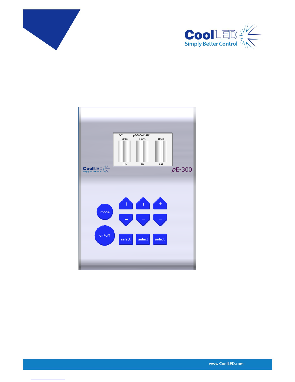
Considering the Control Pod helps explain the control options. Figure 1 shows the
Control Pod for the pE-300
white
(the pE-300
ultra
and pE-340
fura
are very similar).
As shown, the Control Pod consists of three channels that can be either selected or
deselected. The large Global on/off button when ‘on’ will switch on the selected
channels whilst leaving the deselected channels alone. When switched ‘off’ it will
switch off any selected channels that are on.
Each channel can be selected or deselected by pressing the corresponding ‘select’
button. The button marked ‘on/off’ is the Global on/off. Each channel also has its
own intensity control shown above the ‘select’ button. These buttons provide all
possible control on the pE-300
white
.
Figure 1: pE-300
white
Control Pod
DOC-038 Iss 1 4
A TTL-In is also available through the BNC connector on the pE-300
white
and this
performs the same function as the Global on/off button but gives much more
control over precise timing. The pE-300
ultra
and pE-340
fura
also have this BNC but
additionally have individual BNC connections available to further control each
channel.
The channels are named A, B and C from left to right on the Control Pod and the
spectral regions assigned to A, B and C are in increasing wavelength with channel A
being the UV (1UV) or violet* (1V), B is the blue (2B) and channel C covers the green
through yellow to red (3GR).
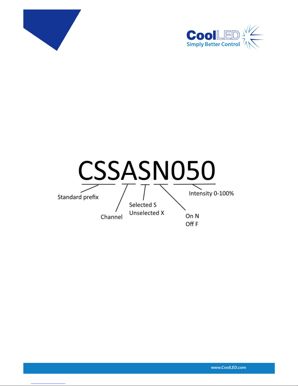
The CSS… commands can be used to select/deselect, turn on/off and also set the
intensity. This command can be used specifically for a single channel or to all three
channels together.
Examples:
• To select channel A but leave it off and set its intensity to 50% the following
command would be used: CSSASF050
• To select channel A and have it on and set its intensity to 50% the following
command could be used: CSSASN050
• To deselect channel A, which can then only be off, and have its intensity at 50% then
the command is: CSSAXF050
N.B. As a default setting the XN state is not allowed through software or Control Pod
control on the pE-300
white
and if used in a command the unit will force that channel
into the XF state.
A longer version of the CSS command can be used as shown in Figure 3:
Figure 2: CSS short command structure

DOC-038 Iss 1 5
The second-long CSS command shown above sets all three channels in a single
command line. In this example ChA is set to the deselected state which is always ‘off’
and at 50% intensity. ChB is set to selected and ‘on’ and 60%, ChC is set to selected
and ‘on’ and at 70%. Notice that the intensity can be described by two or three
digits. In this example, the Global on/off button on the Control Pod will first switch
off ChB and ChC. A second press will switch on ChB and ChC. As ChA is deselected,
the Global on/off will have no effect on it.
The Global on/off commands that will switch on or switch off all selected are:
CSN All selected channels on.
CSF All selected channels off.
The Light Source channel intensities can be set individually using the short or longer
versions of the CSS command as described above. A Global intensity command is
also available which will change the intensity of all three channels but still maintain
the relative intensity between channels. This command is:
CS+ Increment intensity setting on all channels
CS- Decrement intensity setting on all channels
Figure 3: Longer CSS command structure. Not all channels need to be included in the
command and channels can be written in any order after the prefix.

DOC-038 Iss 1 6
If the intensity settings on each channel are identical then this command will
increase or decrease the intensity of each channel by an identical amount of 1%. If
the channels are on different settings then the change will vary between channels in
order to maintain the relative balance.
As shown on the Control Pod screen in Figure 1, the wavelength labels of each
channel are displayed along the bottom of the screen under the channel intensity
bars. This information can also be acquired from the Light Source by the command:
LAMS Elicits information about the wavelengths that are available.
The status of the channels can be provided by using the command:
CSS? Elicits a response giving the status of all channels.
This will elicit a response from the Light Source in the form of the long CSS command
giving details of all channels, as shown in Figure 3.
The pE-300
white
can also be set in a mode that will provide continual reporting of the
intensity of each channel and whether it is set to on or off. The commands to set this
reporting are:
XLIVE=YES Switches on regular reporting of the status of each channel.
XLIVE=NO Switches of this regular reporting.
Information of the level of firmware and hardware of the system can be acquired by
using the following command:
XVER Elicits information about software and hardware versions.
Each command should be in upper case and terminated by a carriage return (CR),
and each response from the pE-300
white
, pE-300
ultra
and pE-340
fura
is terminated by a
carriage return and line feed (CR) (LF).
DOC-038 Iss 1 7
3.2 pE-4000
The pE-4000 Light Source has a similar operating method to the pE-300
white
. The
Control Pod operation will be briefly covered here to explain the control but a more
detailed description can be found in the pE-4000 User Manual.
The pE-4000 Control Pod consists of two distinct regions referred to as the ‘White’
mode and ‘Advanced’ mode. When first switched on the system defaults into the
White mode and can be switched into the Advanced mode by pressing the
‘Advanced’ button. The White mode is intentionally limited in its control options and
is only available through the Control Pod. We will therefore only consider the
Advanced mode on the Control Pod when describing control options available
through software.
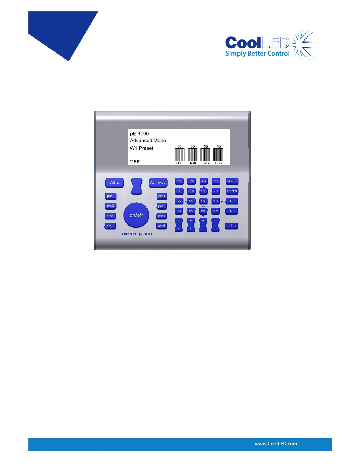
As seen on the pE-4000 Control Pod, four channels of four wavelengths each are
available with each channel aligned vertically in four columns. Channel A is the leftmost column and consists of wavelengths 365, 385, 405 and 435. The next column is
ChB, followed by ChC and ChD as shown in Figure 5.
Figure 4: pE-4000 Control Pod.
 Loading...