

Page 1
MOBILES KLIMAGERÄT MOBILE AIR-CONDITIONER CONDIZIONATORE PORTATILE CLIMATISEUR MOBILE MOBIEL AIRCOTOESTEL
MPK-09CRN2 / MPK1-09CRN1 / MPK1-12CRN1
DE
EN
IT
FR
NL
Page 2
22
Page 3

EN
23
INFORMATION 3
SAFETY INSTRUCTIONS 24
DESCRIPTION OF APPLIANCE 26
ACCESSORIES 27
OPERATION PANEL 28
INSTALLATION AND START-UP 30
INSTRUCTION FOR USE 32
WATER TANK 33
INSTALLATION 35
CLEANING, MAINTENANCE AND STORAGE 37
TROUBLESHOOTING 38
WEEE 39
PURCHASE TERMS AND CONDITIONS/WARRANTY 40
INSTRUCTIONS FOR USE
Page 4

24
CAUTION
DEAR CUSTOMER,
Thank you for buying a product that was developed and checked for the highest claims. Please read the use instructions
document carefully before the first start up, so that you may get to know all the functions of this appliance. Keep the use
instructions document for reference whenever required.
INFORMATION
In summer, one feels good at a temperature between 24°C and 27°C, and a relative humidity of about 50%. Air-conditioners
serve the purpose of recreating this condition even at higher external temperatures and higher humidity levels in the room
by removing humidity and heat from the air in the room.
Unlike permanently installed air-conditioners, mobile models have the advantage that they can be moved from one room to
another and can be transported to another building.
SAFETY INSTRUCTIONS
1. Do not operate this appliance if it is damaged or has damages, or if it does not function properly. Disconnect the power
plug from the power socket.
2. Install the appliance at a place where children cannot reach it.
3. Do not use the appliance:
A: In the vicinity of heat sources, e.g., heater or a heating appliance, clothes dryer, etc.
B: At places where oil and water can be splashed.
C: At places that are directly exposed to the rays of the Sun.
D: In the vicinity of bathtubs, showers or swimming pool.
E: In a greenhouse.
F: In the vicinity of easily combustible gases and substances.
G: Behind curtains or other objects or obstacles that can have an adverse effect on the air circulation.
H: In the open.
4. Always place the appliance in the upright position, so that the compressor can function properly.
5. If the power cable of the appliance is damaged, it must be repaired at a workshop licensed by the manufacturer, as
special tools are required.
Page 5

EN
25
6. Always remove the power plug from the power socket when the appliance is not in use, or when it is moved, touched or
cleaned. Do not yank the cord to disengage the power plug.
7. Always switch the appliance off before disconnecting the power plug from the power socket by activating the POWER
key on the operation panel.
8. Do not remove the water tank when the appliance is in operation.
9. Never insert your finger or other external bodies in the grid or openings. This can lead to overheating, fire or electric
shock. Warn children about these dangers.
10. Do not dip the appliance in water or other liquids and do not shake water or other liquids over the appliance or in the air
inflow and outflow apertures.
11. The appliance must be cleaned regularly. Please observe the cleaning instructions in this context. The appliance must be
disconnected from the power supply before being cleaned.
12. The appliance should not be covered.
13. Do not use insecticide sprays or other sprays on the appliance that can cause fire.
14. The appliance does not contain components that require maintenance by the user. You must send the appliance to the
manufacturer or to Customer Service, if the appliance or the power cable is damaged.
15. Please empty the water tank before transporting the appliance. The appliance must be disconnected from the power
supply for this purpose.
16. For server room cooling, please engage a technician to ensure that the efficiency of the appliance matches your require ments.
Page 6
26
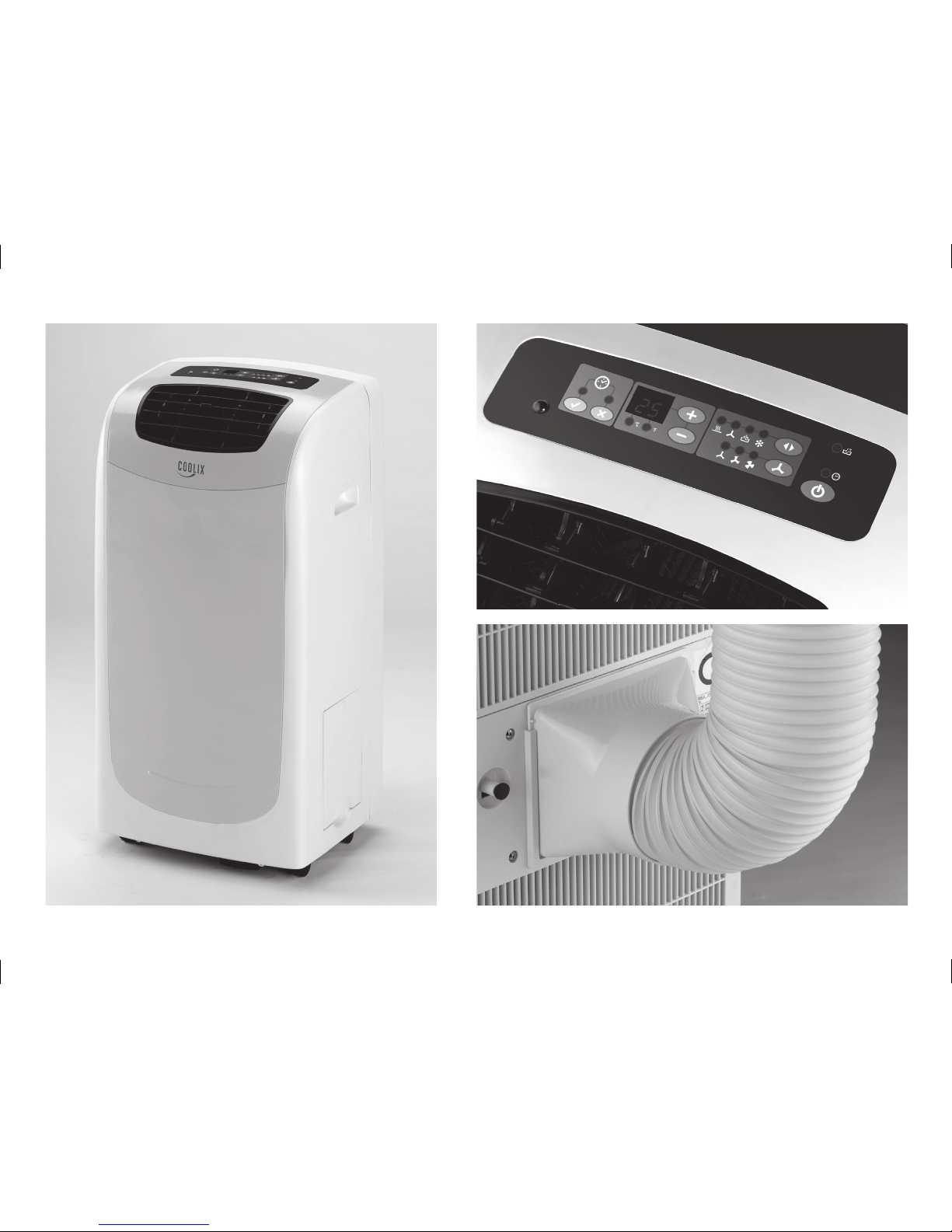
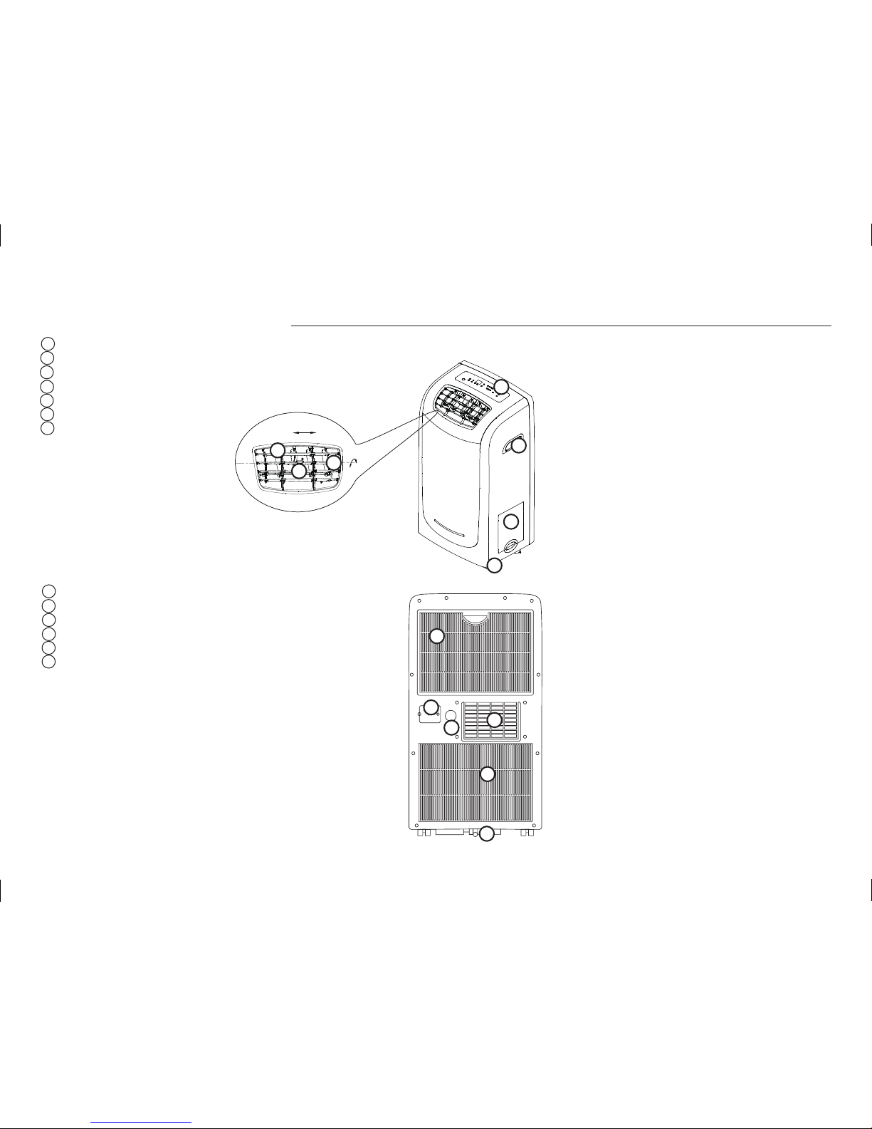
DESCRIPTION OF APPLIANCE
1. Operation panel
2. Vertical ventilation flap
3. Direction regulator
4. Horizontal ventilation flap
5. Supporting handle (on both sides)
6. Water tank
7. Rollers
8. Air filter
9. Fastening tape for power cable
10. Outlet plug
11. Hot air outlet
12. Air entry inlet
13. Bottom outlet plug
1
2
3
4
5
6
7
8
9
10
11
12
13
Page 7
EN
27
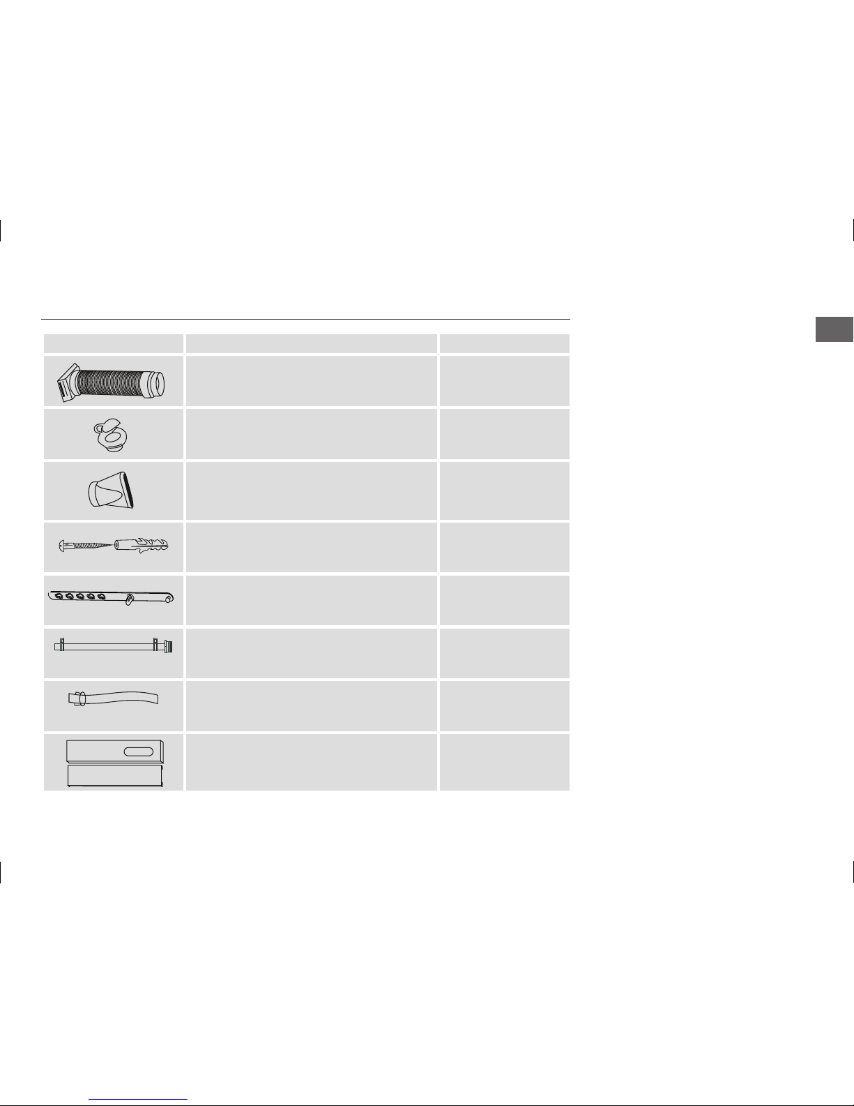
Check whether all the accessories are there in the packaging and read the use instructions to learn how these are to be used.
ACCESSORIES
Figure Designation Number
Exhaust cable 1
Adapter A (for permanent cable mounting) 1
Adapter B (for provisional cable mounting) 1
Expansion plug 4
Tape for fastening power cable 1
Emptying hose (continuous discharge)
(Not available in some models)
1
Emptying hose (connected to the water tank) 1
Window panel set 1
Page 8
28
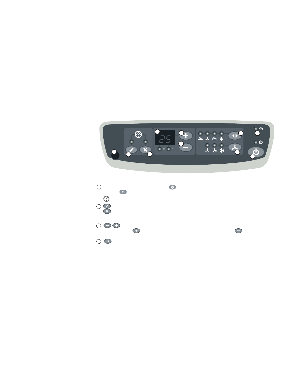
OPERATION PANEL
3
1
2
4
5
7
8
3
1.
You can switch the appliance on by pressing , the adjacent control light lights up now.
Press the key again to deactivate the appliance, the control light goes off.
2.
key: This key is used to determine when the appliance will be switched on automatically.
key: By pressing this key you can determine when the appliance will be switched off automatically.
The control lights on the two keys indicate whether these functions were selected.
3.
key: These keys are used to adjust the desired cooling temperature. The temperature increases by 1°C each
time you press the key, the temperature decreases by 1°C each time you press the key.
4.
key: You can select the mode of the appliance by pressing this key. The mode changes each time you press this
key in the following sequence: Cool – Dehumidify – Fan – Heat.
The currently set mode can be identified from the control light that is illuminated next to the symbol. The Heat mode is
to be selected only in appliances that are equipped with the heating function.
Timer
2
6
Page 9

EN
29
5. key: You can select the fan speed in the Cool and Fan modes by pressing this key. The speed changes
in the following sequence each time you press the key: Low – Medium – High.
The currently set speed can be identified from control light that lights up next to the symbol.
6.
control light: It lights up when the water tank is full or the water tank has not been inserted correctly. The
appliance stops the operation automatically. The water tank must be emptied or positioned correctly.
7. Digital Display: The set temperature is displayed here. The current room temperature is displayed in the Ventilate and
Dehumidify modes. The set values are displayed here when the timer function is set.
Note: The temperature can be displayed and set in °C or °F. Please press the
and keys simultaneously to
change the display. You can view whether the display is in °C or °F with the help of the corresponding control light.
8. Signal receiver for remote control. This receiver does not have any function in appliances that do not support remote
control.
Page 10
30
INSTALLATION AND START-UP
1. Read all the instructions carefully before commissioning the appliance. Observe the safety instructions of this user
manual in particular.
2. The appliance must be in the upright position for at least 24 hours before start up. This condition is applicable most of
all after transportation.
3. Place the appliance on a firm, even surface. Ensure that it is stable so that the appliance does not fall down or topple
over. The discharged water can damage furniture and floor covers.
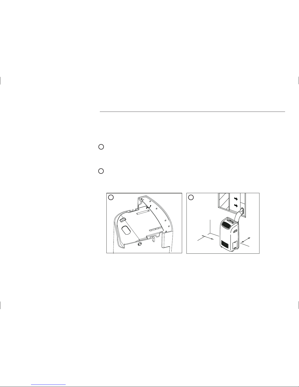
4. This appliance is equipped with a water tank which is fastened with a belt in the factory to protect the water level switch
during transportation. Take the water tank out and remove the fastening tape and replace the water tank in its initial
position before the first start-up. Do not push or apply sudden force on the tank, as this could lead to faults in the
appliance. Information about the correct handling of the water tank is available in the Chapter entitled “Water Tank” in
this use instructions document.
5. Maintain a safety distance of about 30 cm at the front and rear side of the appliance from other objects. The appliance
should not be placed under tables or in cabinets, because then the airflow is restricted.
m
c
0
3
0
3 c
m
4
5
Page 11
EN
31
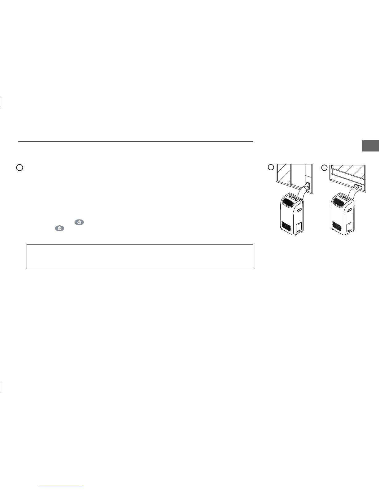
6. Before operating the appliance, please ensure that the air inflow and outflow apertures are not covered. The air exhaust
nozzle must always be freely accessible when the appliance is in operation.
7. Removable covers and tanks must be inserted correctly before switching the appliance on.
8. Position the exhaust air hose and the adjustable window panel set as illustrated in the adjacent figures.
9. Detailed information about the installation of the exhaust air hose and the window panel is available in the Chapter
entitled “Installation” in this use instructions document.
10. Do not use any extension cable, a multi-socket that is also used by other electrical appliances or a continuous speed
regulator. This can lead to overheating, causing a fire.
11. Connect the dehumidifier only to a functioning, single-phase, earthed socket with the mains voltage specified on the
ratings plate. The wall socket should be easily accessible.
12. Unwind the power cord fully and insert the power plug into the power socket. Not unwinding the coiled cord can lead to
overheating, causing a fire. Do not touch the power cable with wet hands.
13. The POWER control light flashes.
14. Now press the
power key to activate the appliance. Press the key again to deactivate the appliance.
8
8
NOTE
Wait for 3 minutes before restarting the appliance after it is deactivated unintentionally (power failure) or
intentionally.
Page 12

32
Cooling
1. Press the key till the control light lights up.
2. Now select the desired room temperature with the help of the
keys.
3. The temperature can be set in the 17°C – 30°C/62°F – 88°F range.
4. You can select the blower speed by pressing the
key.
Dehumidify
1. To achieve better dehumidification, please keep the doors and windows closed.
2. The exhaust air hose must be removed from the appliance if it is in the Dehumidify mode.
3. Press the
key till the control light lights up.
4. You can neither set a definite temperature nor select a definite blower speed in this mode. The appliance runs
at the highest blower speed automatically.
Fan
1. Press the key till the control light lights up.
2. You cannot set a definite temperature.
3. Press the
key to select the blower speed.
4. The exhaust air hose must be removed when the appliance is running in the Fan mode.
Timer function
Automatic mode of the appliance
Press the key when the appliance is switched off and the power plug is inserted in the power socket. 0.0
appears in the display. Press the
key again to determine when the appliance will be switched on automatically. The activation is set back by 30 minutes each time you press the key (from 10 hours to 60 minutes).
For example, the display 9.5 means that the appliance will be activated automatically after 9 hours and 30
minutes. The control light lights up now. The start time can be set between 30 minutes and 24 hours.
INSTRUCTION FOR USE
Page 13

EN
33
Automatic deactivation of the appliance
Press the key when the appliance is switched on. 0.0 appears in the display. Press the key again to determine
when the appliance will be deactivated automatically. The deactivation is set back by 30 minutes each time you press this
key (from 10 hours to 60 minutes). For example, the display 0.5 means that the appliance will stop working after 30 minutes. The control light lights up now. The deactivation time can be set between 30 minutes and 24 hours.
In the Cool and Dehumidify modes, the appliance extracts water from the room air. There are two options of diverting the
water:
Water tank
1. The water is diverted to the water tank and collected there. The appliance is shut off automatically as soon as the water
tank is full the control light starts flashing.
2. Wait for a few minutes before taking the water tank out, so that the remaining water can drip into it. Do not take the
water tank out when the appliance is under operation. Overflowing water can damage objects and floor covers, or lead to
an electric shock.
3. To empty the water tank, take it out as shown, and drain the water in the water tank fully.
4. Now insert the water tank in the initial position and switch the appliance on again. The control light goes off.
WATER TANK
3
Page 14

34
5. In the Dehumidify mode, you also have the option of connecting the attached emptying hose (refer to Figure) to the outlet
plug on the rear side of the appliance, and then of guiding it to the water tank. This way the condensed water flows
through the hose into the water tank. Empty the water tank as described above when it is full.
Continuous water discharge
1. For a continuous water discharge, remove the outlet plug on the rear side of the appliance and install a fitting hose.
Ensure that the hose and the outlet plug are tight and guide the open end to an external water outlet.
2. Make sure that the entire length of the hose is inclined, and that it is not damaged, entangled or clogged, so that water
can flow freely and without any interruption.
3. Check regularly to ensure that the water hose is installed properly is tight.
4. This emptying method lowers the cooling efficiency. Hence, for optimal cooling performance, you should collect and
remove the water with the help of the water tank.
Remove the outlet plug on the rear
side of the appliance.
Take out the outlet plug in the water
tank.
Position the emptying hose.
5
5
5
1
1
Page 15

EN
35
1. To ensure optimal performance of the appliance, the warm air must be guided out of the room.
2. To do this, move the exhaust air hose as illustrated in the figure, with one end over the hot air outlet.
3. There are two options of transporting the hot air in the outward direction:
Temporary installation
Mount Adapter B at the loose end of the exhaust air hose
1. You can now simply let it hang out of the window, which must be closed as far as possible to prevent hot air from
returning to the room or to prevent fresh hot air from outside from entering the room.
2. Or you can use the attached window panel set. In most cases, this set can be applied vertically or horizontally to the
closing standard window. The panel is pushed to the required length and “clamped” to the window frame while closing
the window. You can introduce Adapter B in the hole in the panel.
INSTALLATION
2
Window panel set minimum: 67.5 cm (2.22ft)/ maximum: 123 cm (4.04ft).
If the window opening is smaller than the specified minimum length of the window panel, please shorten one side of
the panel so that it can be inserted. Do not shorten the side of the panel in which the hole is located.
Page 16

36
Permanent installation
1. Drill an appropriately big hole in the outer wall. It should be maximum 120 cm and minimum 30 cm from the floor.
2. Now fix Adapter A with the help of four expansion plugs and screws.
3. Fix the loose end of the exhaust hose (which you used earlier in the appliance – see above) on Adapter A.
4. You can cover the opening in the wall with the adapter cap when you do not want to use the appliance.
5. The cable can be compressed or stretched in the 50 cm to 200 cm range. The appliance works more effectively when the
cable length is maintained as short as possible.
NOTE
Do not bend the cable sharply.
Page 17

EN
37
We recommend the frequent cleaning of the appliance. Follow the instructions on cleaning, maintenance and storage of the
appliance to avoid possible damage to the functioning of the appliance.
Important principles:
1. Do not use petrol, thinner or other chemicals to clean the appliance.
2. Do not clean the appliance by placing it directly under a running water tap or in a water tank. The electrical components
inside it can be damaged, leading to electric shocks.
3. Always disconnect the power plug of the appliance before cleaning.
Air filter
Clean the air filter at least once every two weeks to ensure dust-free operation of the lower blower.
1. Take out filter
Remove the filter cover and take out the air filter from the filter cover.
2.
Clean filter
Dip the air filter in hot water (app. 40°C/104°F) and wash with a neutral detergent. Flush the filter carefully and dry it in a
shady place.
3. Insert filter
Replace the air filter in the filter cover with the help of the fastening hooks on the inner side of the cover. Now mount the
filter cover on the appliance.
Housing of the appliance
1. Use a cloth dipped in a neutral lint-free detergent to clean the appliance housing.
2. Finally wipe with a clean, dry cloth.
Power cable
1. Press the clip carefully in the downward direction and pull the cover out at the front.
2. Wind the power cable properly.
CLEANING, MAINTENANCE AND STORAGE
Page 18

38
Storage
1. If you do not want to use the appliance for a long time, please remove the bottom outlet plug on the rear side of the
appliance and drain the water in the container below the appliance (if necessary, with the help of the discharge hose).
2. Insert the plug again.
3. Ensure that the power cable is wound correctly and it cannot be damaged.
Please check the following possibilities before contacting the manufacturer or his representative:
TROUBLESHOOTING
Problem Possible cause Solution
The appliance does not start when the
key is pressed.
The display flashes, the water
tank is full
Empty the water in the water tank.
The room temperature is higher than
the set temperature (Heat mode).
Readjust the temperature.
The room temperature is lower than
the set temperature (Cool mode).
Readjust the temperature.
Inadequate cooling Windows and doors are not closed. Ensure that all the windows and doors
are closed.
There are heat sources in the room. Remove the heat sources to the extent
possible.
The exhaust air pipe is not connected
or it is blocked.
Connect the pipe and ensure that it
can function properly.
Page 19

EN
39
Problem Possible cause Solution
Inadequate cooling Temperature setting is too high. Lower the set temperature.
The air filter is clogged with dust. Clean the air filter.
Power deactivation in Heat mode Automatic overheating protection
function. The appliance is switched off
automatically when the temperature
at the air outlet exceeds 70°C/158°F.
Reactivate the appliance after it has
cooled down.
Loud or vibrates The base is not adequately firm or flat. Place the appliance on a flat, firm
base.
Sound The sound comes from the flowing of
the coolant in the air-conditioner.
This is normal.
Compressor does not function and the
digital display shows “P2”
The bottom container is full. Remove the plug from the bottom
outlet and let the water out.
The packaging material of this appliance can be recycled. Please dispose the packaging material according to
the guidelines of your local garbage disposal authorities.
This appliance consists of recyclable materials and can be channelized for reuse – after sorting by a
specialized agency.
WEEE
Page 20

40
As purchase terms, the buyer will takeover the responsibility of correct use and maintenance of the product according to this
instructions for use document. The buyer and user must himself decide how long the appliance is to be used.
If you face problems with this product, please observe the instructions in the guarantee terms and conditions. Please do not
try to open the appliance on your own or to repair it, as this will nullify the guarantee and can lead to bodily and material
damages.
PURCHASE TERMS AND CONDITIONS
Technical changes and printing errors reserved.
Please read all instructions before attempting to use this product. Please retain your proof of purchase which shows date of
purchase in the unlikely event of a future warranty claim. See paragraphs 1 and 3 for exclusions.
1. This 3 year warranty applies to repair or replacement of product found to be defective in material or workmanship. This
warranty does not apply damage resulting from abusive or unreasonable use or supplement damage. Defects that are
the result of normal wear and tear will not be considered manufacturing defects under this warranty. The manufacturer is
not liable for incidental or consequential damages of any nature. Any implied warranty including merchantability or
fitness for a particular purpose on this product is limited in duration of this warranty. Some states or countries do not
allow the exclusion or limitation of incidental or consequential damages or limitation how long an implied warranty lasts,
so the above limitations or exclusions may not apply to you. This warranty gives you specific legal rights, and you may
also have other rights which vary form region to region. This limitation does not apply to you if you live in those states or
countries that do not permit the exclusion or limitation of incidental or consequential damages. This warranty only applies
to the original purchaser of this product. This warranty does not cover any filter elements which may be included with this
product, except for defects in material or workmanship. Not all products include filtration devices. For further information,
please refer to the specified positions on the reverse.
2. As its option, the manufacturer will repair or replace this product if it is found to be defective in material or workmanship.
3. This warranty does not cover damage resulting from any unauthorized attempts to repair or from any use not in
accordance with this manual.
WARRANTY
Page 21

EN
41
Page 22

MIDEA EUROPE GmbH
Zülpicher Str. 5
40549 Düsseldorf
Germany
Service-Hotline DE 01805 - 12 16 17
(14 Cent pro Minute aus dem deutschen Festnetz)
Service-Hotline Europe 0049 - 1805 - 12 16 17
www.mideaaircon.de
info@mideaaircon.de
12/2006 – CS384-U
Page 23

FERNBEDIENUNG REMOTE CONTROL TELECOMANDO TELECOMMANDE AFSTANDSBEDIENING
DE
EN
IT
FR
NL
Page 24

12
Page 25

EN
13
SPECIFICATIONS 14
PERFORMANCE CHARACTERISTICS 14
KEYS 15
DISPLAY 16
OPERATION 17
SAFETY INSTRUCTIONS 20
INSTRUCTIONS FOR USE
Page 26

14
SPECIFICATIONS
Model R51H, R51H/C
Nominal voltage 3.0 V (Alkali-dry cells LR03 x 2)
Lowest voltage of processor transmission signal 2.0 V
Transmission distance
8m
Environment -5°C ~ 60°C
PERFORMANCE CHARACTERISTICS
1. Mode: AUTO, COOL, DRY, HEAT, and FAN
2. 24 hours timer
3. Adjustment range of room temperature: 17°C ~ 30°C
4. LCD display
1. Read this use instructions document before using the remote control.
2. Keep this document for reference at a safe place.
3. All data in this document pertaining to the HEAT mode are applicable only to
air-conditioners that are equipped with the Heat function.
4. The air-conditioner responds with a delay of about 3 minutes if you switch it
on after it has been switched off.
INFORMATION
Page 27

EN
15
KEYS
1. TEMP : The room temperature setting decreases
on pressing this key.
2.
TEMP : The room temperature setting increases on
pressing this key.
3. MODE: This key can be used to select the mode
of the appliance. The mode changes in the following
sequence each time you press this key:
AUTO – COOL – DRY – HEAT – FAN.
5.
RESET: All user-defined settings are deleted on
pressing this key, and the system is reset to the
original factory settings.
8. FAN SPEED: This key can be used to select the
speed of the blower. The speed changes in the
following sequence each time you press this key:
LOW – MED – HIGH – AUTO.
9. ON/OFF: Press this key to switch the appliance on.
Press it again to stop the operation.
10.
TIMER ON: Press this key to define the activation
period of the appliance. The activation time is set
back by 30 minutes, each time you press this key
(from 10 hours in hourly cycle). To deactivate this
mode, all you have to do is simply set 0:00.
>
>
12. TIMER OFF: Press this key to define the deactiva tion time of the appliance. The deactivation time is
set back by 30 minutes each time you press this
key (from 10 hours in hourly cycle). Just set the
value to 0.00 to deactivate this mode.
13. LOCK: Press this key to lock all the current settings,
and the remote control will not allow any mode
other than LOCK. Press it again to release the LOCK
mode.
1
2
3
4
6
7
8
9
5
SET TEMPERATURE( /F )
AUTO
COOL
DRY
HEAT
FAN
HIGH
MED
LOW
TEMP
MODE
FAN
SPEED
TIMER
OFF
LOCK
RESET
ON/OFF
TIMER
ON
C
1
3
7
5
8
9
2
4
9
Page 28

16
DISPLAY
1. DIGITAL DISPLAY RANGE: This range basically displays the set temperature. The corresponding settings of the TIMER
are displayed in the TIMER mode. There is no display in the FAN mode.
2.
TRANSMISSION SIGNAL: This arrow lights up when the remote control transmits signals to the display panel of the
appliance.
3.
ON/OFF
: This symbol appears when the remote control activates the appliance, and it disappears when it is
switched off.
4.
MODES: An arrow appears before the concerned selected mode on pressing the MODE key.
5.
LOCK: The LOCK display appears on pressing the LOCK key. Press the LOCK key again and the display disappears.
6. TIMER DISPLAY: TIMER OFF appears in this area as soon as you select an activation time. Similarly, TIMER OFF appears
in this area as soon as you select a deactivation time. TIMER ON OFF appears if both functions are selected.
7. FAN SPEED DISPLAY: An arrow appears in front of the concerned selected blower speed when you press the FAN
SPEED key (exception: No display if you select AUTO speed).
1
2
3
4
5
6
7
NOTE
The displays shown here are to facilitate understanding only. Only the selected functions are displayed when the
appliance is in operation.
AUTO
COOL
DRY
HEAT
FAN
HIGH
MED
LOW
1
2
3
4
5
6
7
Page 29

EN
17
OPERATION
Insert/replace cells
The remote control requires two alkaline dry cells (LR03X2).
1. To insert the cells, remove the cover of the cell compartment and then insert the cells. Please ensure that the cells are
positioned correctly (+/-).
2. Follow the same method to replace old cells.
Switch the air-conditioner on by inserting the power plug into the power socket (refer to the Instructions for Use document of
the appliance). You can now use the remote control.
NOTE
1. Do not use old or different units while replacing cells. This can lead to disturbances in the remote control.
2. Remove the cells if you do not want to use the remote control for several weeks. Leaking cells can damage the remote
control.
3. Under conditions of normal use, the average life of the cells is about 6 months.
4. Replace the cells if the air-conditioner does not respond with a whistle or if the transmission control light no longer
lights up.
Page 30

18
A AUTO mode
1. Select the AUTO mode by pressing the MODE key.
2. Select the desired room temperature by pressing the TEMP keys. The most pleasant temperature settings are in the
21°C to 28°C range.
3. Press the ON/OFF key to start the air-conditioner.
The FAN SPEED – i.e., the speed of the fan is set automatically.
4. Press the ON/OFF key again to stop the operation.
B COOL, HEAT and FAN mode
1. You can select the desired COOL, HEAT or FAN mode by pressing the MODE key.
2. Select the desired room temperature by pressing the TEMP keys. The most pleasant temperature settings fall in the
21°C to 28°C range.
3. You can press the FAN SPEED key to select the speed of the fan. The speed is selected in the following sequence each
time you press the key: AUTO – LOW – MED – HIGH.
4. Press the ON/OFF key to start the air-conditioner.
5. Press the ON/OFF key again to stop the operation.
NOTE
1. In the AUTO mode, the air-conditioner selects the COOL, FAN or HEAT mode automatically by detecting the temperature
difference between the actual room temperature and the set temperature.
2. The COOL, FAN and HEAT modes can also be selected manually.
NOTE
The FAN mode cannot be used to regulate the temperature. Only Steps 1, 3, 4 and 5 can be performed in this mode.
Page 31

EN
19
C DRY mode
1. Select the DRY mode by pressing the MODE key.
2. Select the desired room temperature by pressing the TEMP keys. The most pleasant temperature settings are in the
21°C to 28°C range.
3. Start the air-conditioner by pressing the ON/OFF key.
The air-conditioner is now running in the DRY mode at low blower speed.
4. Press the ON/OFF key again to stop the operation.
D TIMER mode
Press the TIMER ON key to adjust the automatic activation period of the appliance, and the TIMER OFF key to set the automatic deactivation period of the appliance.
Setting the activation period (deactivation period):
1. Press the TIMER ON (TIMER OFF) key. The display of the remote control now shows TIMER ON (TIMER OFF), the last set
time for start (stop) of operation and the symbol “h”. You can now set the period for operation start (stop).
2. The activation time (deactivation time) is set back by 0.5 hours each time you press the TIMER ON (TIMER OFF) key
(from 10 hours in 1 hour-cycle).
3. After setting the activation (deactivation period), it takes about 30 seconds for the signal to be transmitted from the
remote control to the air-conditioner. The set functions as well as TIMER ON (TIMER OFF) appear in the display after
another 2 seconds.
NOTE
Due to differences in the set temperature of the appliance and the actual room temperature, the air-conditioner frequently starts in the DRY mode automatically without the COOL and FAN modes.
INSTRUCTIONS
1. TIMER ON OFF is displayed if you have set an activation time as well as a deactivation time.
2. Press the corresponding TIMER key and reset the period to change the TIMER ON/OFF time.
3. Set the TIMER period to 0:00 to delete the TIMER ON/OFF setting.
Page 32

20
1. There should be no barrier between the remote control and the receiver of the air-conditioner; otherwise the
air-conditioner will not function.
2. Keep the remote control away from all liquids.
3. Protect the remote control from high temperatures and direct sunlight.
4. Do not expose the signal reciever of the air-conditioner to direct sunlight because otherwise the air-conditioner may not
function properly.
5. Keep the remote control away from electro-magnetic radiation emanating from other household appliances.
SAFETY INSTRUCTIONS
Technical changes and print errors reserved.
Page 33

EN
21
Page 34

MIDEA EUROPE GmbH
Zülpicher Str. 5
40549 Düsseldorf
Germany
Service-Hotline DE 01805 - 12 16 17
(14 Cent pro Minute aus dem deutschen Festnetz)
Service-Hotline Europe 0049 - 1805 - 12 16 17
www.mideaaircon.de
info@mideaaircon.de
12/2006 – CS259-R
 Loading...