

Page 1
INSTALLATION,
OPERATION
&
MAINTENANCE
MANUAL
CONCEALED CHILLED WATER VERTICAL FAN COIL UNITS
'VWL' SERIES
Page 2

INDEX
Contents Page
Model decoding ........................................................................................................................................ 2
Options ..................................................................................................................................................... 2
General information .................................................................................................................................. 3
Warranty terms ......................................................................................................................................... 3
Inspection procedures .............................................................................................................................. 3
Safety issues ............................................................................................................................................ 3
Installation procedures ............................................................................................................................. 4
Location of units ....................................................................................................................................... 4
Site preparation ........................................................................................................................................ 4
Indoor unit installation .............................................................................................................................. 4
Piping connection ..................................................................................................................................... 5
Condensate drain connection ................................................................................................................... 5
Electrical connection ................................................................................................................................ 5
Unit dimensions ........................................................................................................................................ 6
Coil connection dimensions...................................................................................................................... 6
Typical wiring diagram ........................................................................................................................... 7-8
Valve packages ........................................................................................................................................ 9
Parts list ................................................................................................................................................... 9
Thermostat operation & specification data ........................................................................................ 10-11
Maintenance ........................................................................................................................................... 12
CONTINUING RESEARCH RESULTS IN STEADY IMPROVEMENTS.
THEREFORE, THESE SPECIFICATIONS ARE SUBJECT TO CHANGE WITHOUT NOTICE.
1
Page 3
MODEL DECODING
1, 2 & 3
BASIC(SERIES)
VWL
COOLINE
CONCEALED
CHILLED
WATER FAN
COIL UNIT,
VERTICAL
SERIES
4 & 5
SIZE
(x 100 CFM)
03
04
06
08
10
6
ELECTRICAL
SUPPLY (V-Ph-Hz)
B:220/240-1-50
7
COIL
A :
3 ROW CHILLED
WATER
J :
3 ROW CHILLED
WATER + 1 ROW
HEAT
8
HEATER
N :
NO HEATER
E :3 kW
F :4 kW
NO HEATER
N :
G:5 kW
H :6 kW
J :7 kW
9
ACCESSORIES
N : STANDARD
B :
3D VALVE PACKAGE
(COOL ONLY)
K :
4D VALVE PACKAGE
(HEAT & COOL)
10
FIN
A : ALUMINUM
FIN
B : COATED
ALUMINUM
FIN
C : COPPER FIN
11
COIL
CONNECTION
R : RH SIDE,
STANDARD
(FACING AIR
DISCHARGE)
L :LH SIDE,
OPTIONAL
(FACING AIR
DISCHARGE)
12
FILTER
N : NONE
A :
ALUMINUM
(1" THICK)
13
OPTION
N :
STANDARD
UNIT
OPTIONS
ELECTRICAL HEATERS
The heating element is made of tubular finned sheath coil of the highest grade resistance wire precisely centered in a 1/2"
dia. Copper plated steel sheath and insulated from the sheath by magnesium oxide powder. Through the application of
mechanical force, the powder is packed to a rock like density, insuring rapid heat dissipation from the resistance coil to the
sheath section at each end of the element is unheated to remove source of heat from the terminals. The surface area
exposed to the air is increased by the application of 1-1/4" OD fins. The fin is made of steel wound around the element in
a continuous spiral which makes five turns per linear inch of element. The sheath and fin are permanently bonded together
by copper brazing.
VALVE PACKAGES
Valve packages, as a set are available as an option (3D for two-pipe system and 4D for four-pipe system). These valves are
supplied loose for field installation.
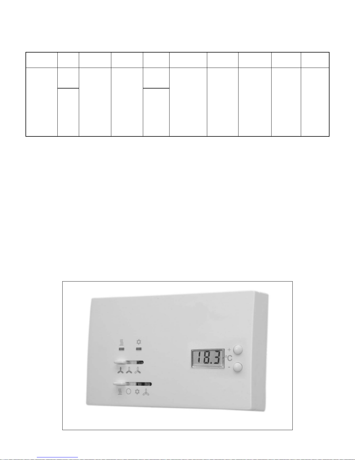
THERMOSTAT
An attractive wall mount three speed thermostat with all required functions and features for safe and smooth operation
which can be used for cooling & heating. This thermostat can be supplied loose through separate Kit number.
TYPICAL THERMOSTAT
2
Page 4
GENERAL INFORMATION
Thank you for your purchase of this equipment from the COOLINE Air Conditioners. We trust that this unit will provide you
with the proper Cooling/Heating requirements for years to come.
This unit has been tested to the extremes in terms of working conditions and successfully passed all the requirements of
quality, safety and performance.
However, we would suggest that you read carefully this manual before you proceed with the installation and operation of
this equipment and follow the instructions for a safe, trouble free operation.
WARRANTY TERMS
All of the VWL series of indoor vertical fan coil (concealed) units are covered by the standard warranty terms against any
manufacturer defect. Should you encounter any problem that falls under the warranty terms please contact your nearest
COOLINE representative.
INSPECTION PROCEDURES
The moment you receive this unit, check the packaging carton for any visible damage due to shipment and mishandling.
If you suspect any damage to the unit please call your nearest COOLINE representative.
After you open the carton, make sure that there is no visible damage to the body. Check the condition of the protective
Styrofoam. Manually rotate the blower wheels to make sure that it is running freely.
NOTE: Any damage, visible or concealed should be reported immediately to the delivery man or driver and noted on the
shipping invoice.
Inside every VWL packaging you will find:
- VWL Concealed FCU 1 No
- Service Manual 1 No
SAFETY ISSUES
When performing any task pertaining to the installation and servicing of the unit, the skilled technician should observe the
following safety measures:
WARNING:
Electric shock hazard and / or serious injury from rotating parts can result from improper handling and
servicing. Only skilled and trained technicians should attempt at installing and servicing these units.
CAUTION:
Improper handling and operating procedures might adversely affect the proper functioning of the unit.
Please read carefully this manual before operating the unit.
3
Page 5
INSTALLATION PROCEDURES
A. Location of units
The Indoor FCU should be ideally located in a floor or
hung to a wall that is near to the conditioned area where
the access to the chilled water piping connection is easy.
Position the FCU in a way to avoid obstruction to return
airflow, supply air, electrical cable connections,
condensate drain pipe and chilled water piping.
B. Site Preparation
The site for the FCU installation should be free from any
obstacle that can be hazardous to the installation
personnel and/or damaging to the unit.
Properly identify all existing building utilities (such as
electrical cables, plumbing pipes, sanitary hardware,
etc.).
Make sure that live electrical cables are not hanging or
running near the FCU proposed location or obstructing
in any way the movement of the installation personnel.
Clear the floor from all objects with sharp edges.
Remove liquid or slippery material from the installation
site before proceeding.
FIGURE - 1
C. Indoor unit installation
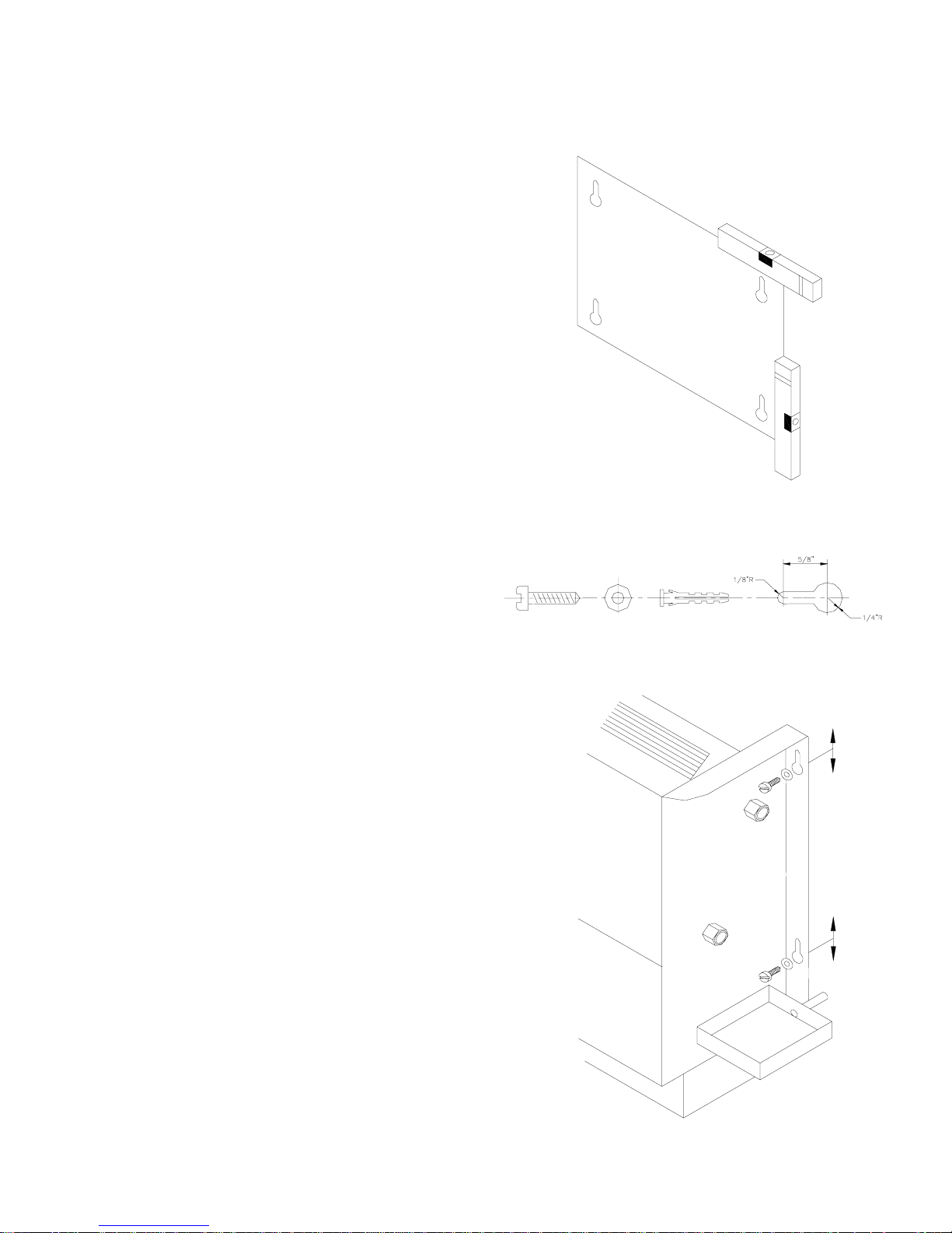
Unit can be installed on the floor or mounted on the wall.
After unpacking the unit, cut the rear carton panel and
mark it with a sketch simulating the FCU. Use it as a
template for positioning the unit and marking the
corresponding mounting slots to the wall.
- Put the template against the wall and mark the
corners. Make sure that you leave sufficient space/
clearance for unit maintenance, chilled water piping
and control valve connections.
- Transfer the mark from the template to the wall as
shown in figure-1.
- Drill 4 holes if the unit is to be mounted on the wall.
Make only 2 holes (top and each side) for floor
mounted units.
- After drilling the holes, insert wall plugs into the
holes and install suitable screws with washers as
shown in figure-2.
- Lift the unit and engage the screws in the slots
(figure-3).
FIGURE - 2
- Tighten the screws.
FIGURE - 3
4
Page 6
D. Piping connection
MODEL NUMBER
VWL 03
VWL 04
VWL 06
VWL 08
VWL 10
SWEAT CONNECTION
WATER INLET WATER OUTLET
5/8"
5/8"
5/8"
5/8"
5/8"
5/8"
5/8"
5/8"
5/8"
5/8"
Note: The water lines must be installed level in both the horizontal & vertical plane.
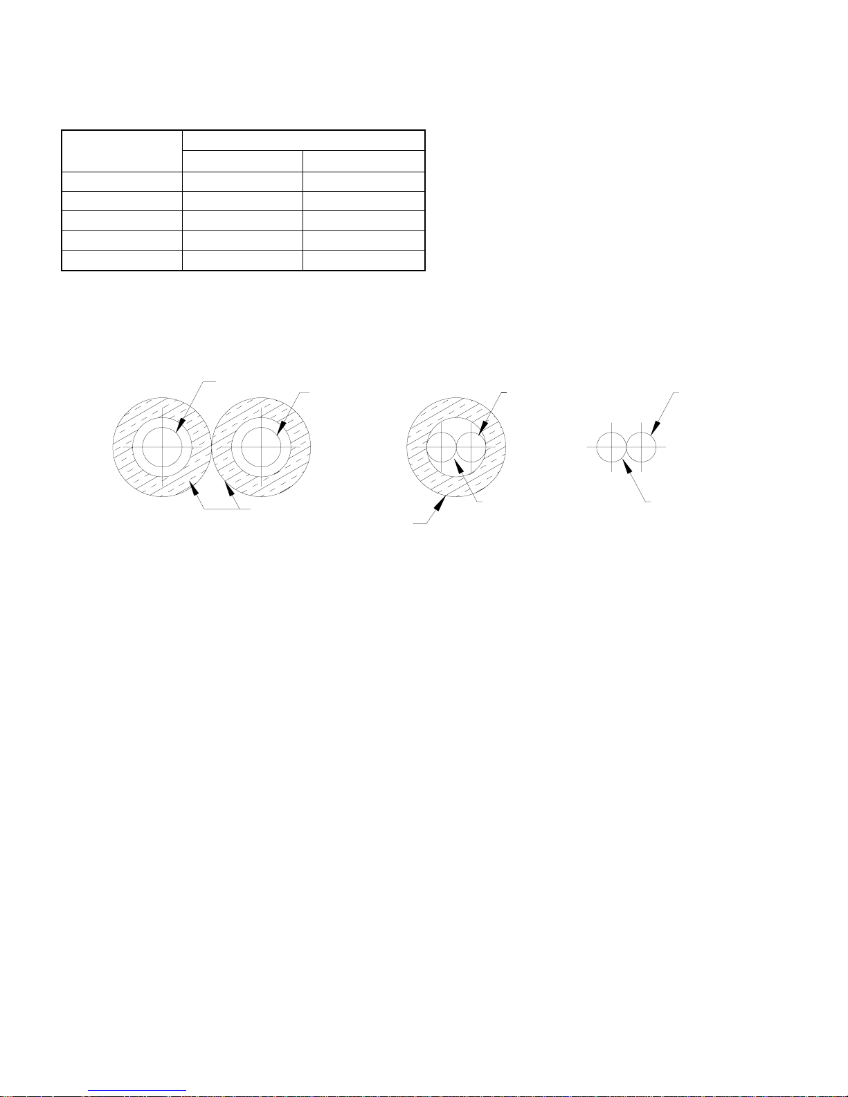
Insulation of pipes
The pipe insulation should cover both inlet & outlet pipes as shown below.
WATER IN
INSULATION
WATER OUT
WATER OUT
INSULATION
WATER OUT
WATER INWATER IN
NO NOYES
E. Condensate Drain connection
- Use PVC Class 3 material for the condensate drain piping (3/4").
- Provide a "P" trap immediately at the condensate drain connection.
- Run your piping avoiding bends and elbows.
- Pitch the piping away from the unit with 2/100 slope.
- If the pipe is routed though a room (or an unconditioned space) insulate to avoid condensation on its outer walls.
F. Electrical connection
Please ensure power supply (V-Ph-Hz) to the unit is as per unit nameplate requirements.
Caution: Operation of the unit on improper power supply will result in damage to the unit.
Warning: Before installation or servicing, always TURN OFF all power to the unit. There may be more than one discon-
nect switch. Ensure all of them are turned off.
Ground & Power wires
Connect power wires as per wiring diagram. Connect ground wire to the ground lug inside the control box.
5
Page 7
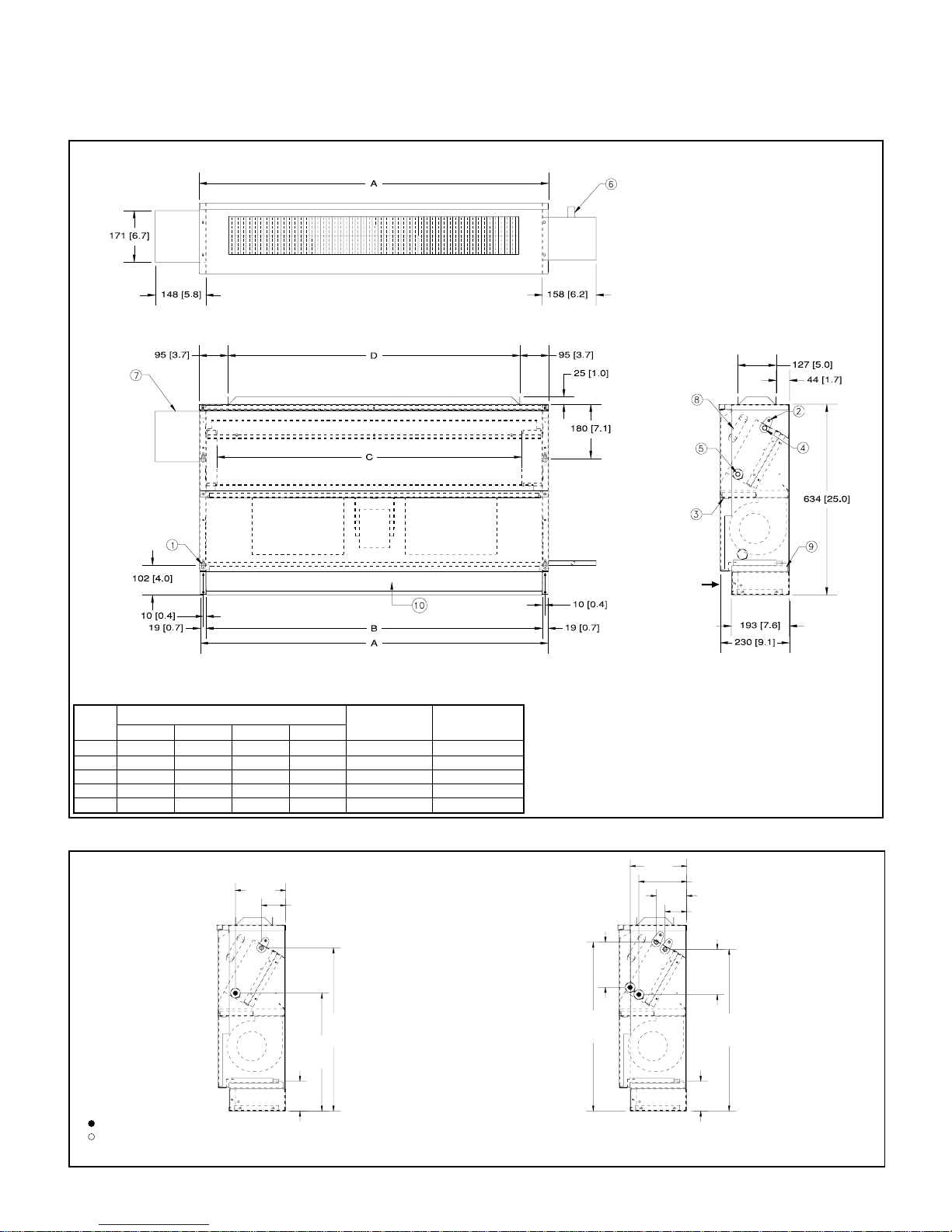
UNIT DIMENSIONS
MODELS: VWL03 - VWL10
TOP VIEW
NOTE: All dimensions are in mm (dimensions in brackets are in inches).
MODEL
VWL03 597 (23.5) 559 (22) 457 (18) 406 (16) 1 1
VWL04 851 (33.5) 813 (32) 711 (28) 660 (26) 1 2
VWL06 1105 (43.5) 1067 (42) 965 (38) 914 (36) 1 2
VWL08 1511 (59.5) 1473 (58) 1372 (54) 1321 (52) 2 4
VWL10 1715 (67.5) 1676 (66) 1575 (62) 1524 (60) 2 4
ABCD
DIMENSIONS
No. OF MOTORS
No. OF BLOWERS
COIL CONNECTION DIMENSIONS
171 [6.7]
82 [3.2]
555 [21.9]
401 [15.8]
FRONT VIEW
1. Mounting holes (4 No.)
2. Air vent
3. Drain pan
4. 5/8" OD coil outlet
5. 5/8" OD coil inlet
6. 7/8" OD drain
7. Control box
8. Heater
9. Filter
10.Return air
154 [6.1]
575 [22.6]
RETURN AIR
END VIEW
193 [7.6]
163 [6.4]
104 [4.1]
74 [2.9]
154 [6.1]
550 [21.7]
102 [4.0]
INLET
OUTLET
NOTE: All dimensions are in mm (dimensions in brackets are in inches).
102 [4.0]
CHILLED WATER & HOT WATERCHILLED WATER
6
Page 8
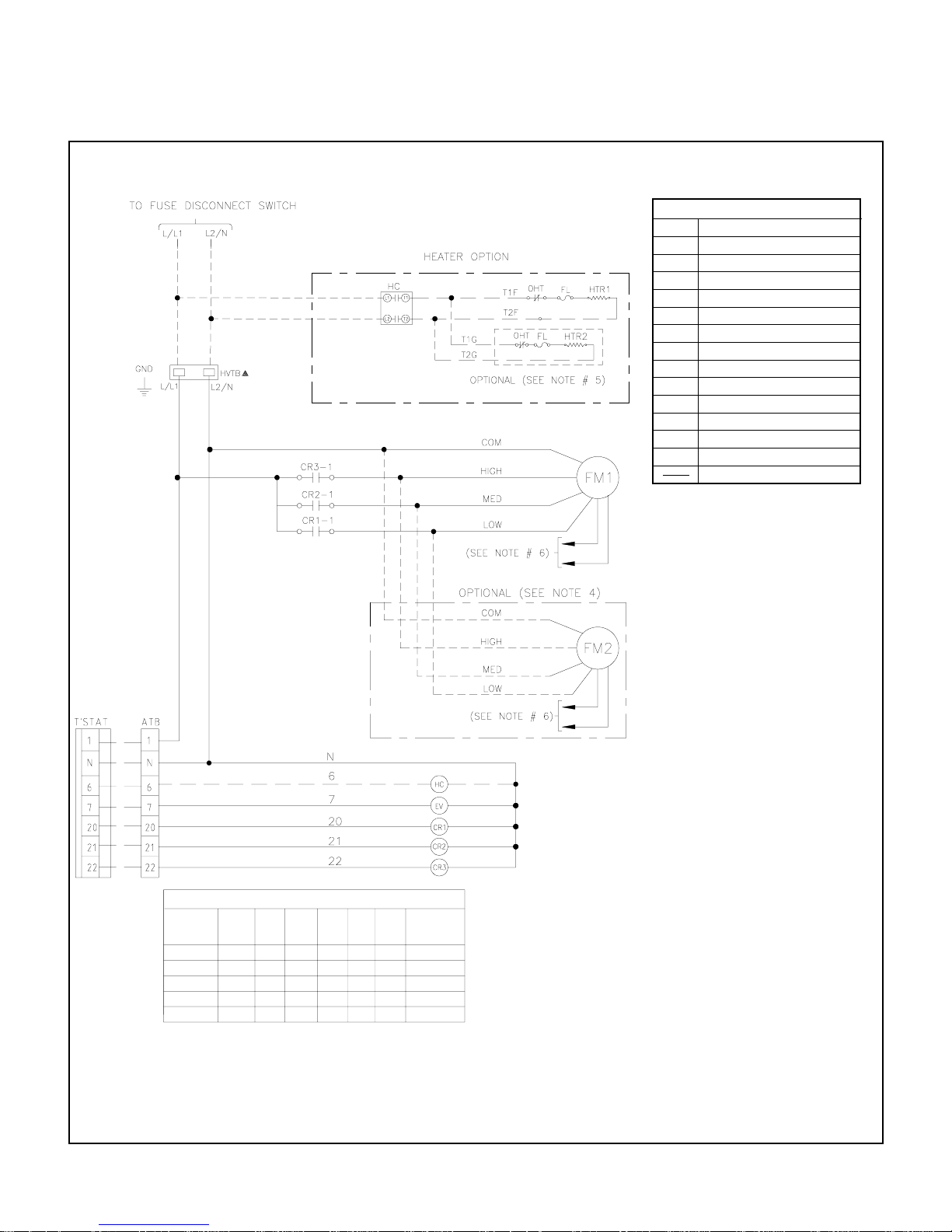
TYPICAL SCHEMATIC WIRING DIAGRAM
HEAT/COOL MODELS - ELECTRIC HEATER
ATB AUXILIARY TERMINAL BLOCK
COM COMMON
CR CONTROL RELAY
EV ELECTRIC VALVE (COOLING)
FL FUSE LINK
FM FAN MOTOR
GND LUG GROUND
HC HEATER CONTACTOR
HTR HEATER
HVTB HIGH VOLTAGE TERMINAL BLOCK
L/L1 LINE OR LINE 1
L2/N LINE 2 OR NEUTRAL
OHT OVER HEAT THERMOSTAT
_ _ _
FIELD WIRING
FACTORY WIRING
1. POWER SUPPLY, 220/240V-1PH-50Hz.
2. USE COPPER CONDUCTOR WIRES ONLY.
3. USE HEATER AS PER OPTION REQUIRED. IF
HEATERS ARE FACTORY INSTALLED, PLEASE
READ BROKEN LINES AS CONTINUOUS LINES.
4. FM2 NOT REQUIRED FOR SINGLE MOTOR
AHU. IF FM2 IS FACTORY INSTALLED, PLEASE
READ BROKEN LINES AS CONTINUOUS LINES.
5. HEATER 2 IS NOT REQUIRED FOR SINGLE
HEATER CIRCUIT.
6. FREE END OF FAN MOTOR LEADS TO BE
CAPPED WITH CRIMPABLE WIRE NUT.
7. HVTB NOT REQUIRED FOR HEATER MODELS.
8. MOTOR THERMALLY PROTECTED..
9. FUSED DISCONNECT SWITCH OR CIRCUIT
BREAKER TO BE PROVIDED BY CONSUMER
WITH RATING AS RECOMMENDED BY MANUFACTURER.
LEGEND
NOTES
FACTORY WIRED MOTOR LEADS
MODEL
VWL 03
VWL 04
VWL 06
VWL 08
VWL 10
(WHT)
COM
COM
COM
COM
COM
(BLK)
HIGH
HIGH
HIGH
HIGH
HIGH
(YEL)
(BLU)
MED
MED
MED
MED
MED
(ORN)
APPLICABLE
(RED)
FREQUENCY
IN HZ
LOW
LOW 50
LOW 50
LOW 50
LOW
50
50
7
Page 9
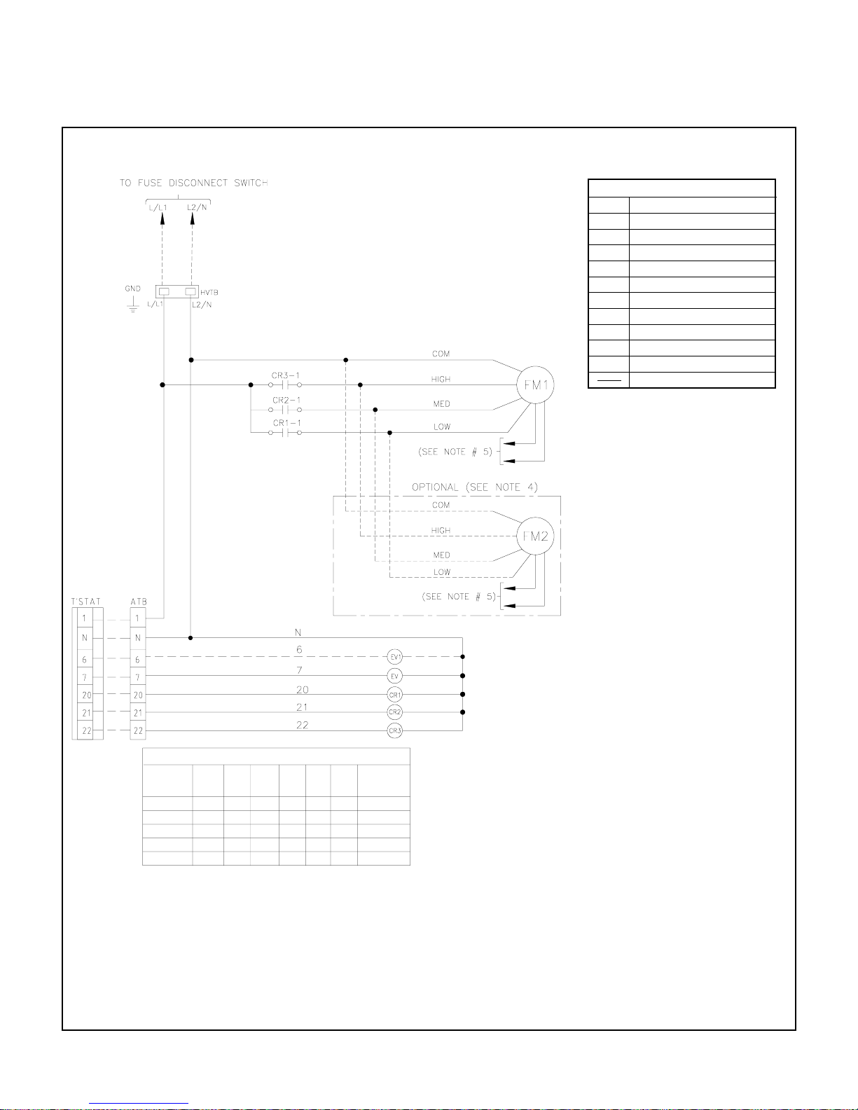
TYPICAL SCHEMATIC WIRING DIAGRAM
HEAT/COOL MODELS - HOT WATER
ATB AUXILIARY TERMINAL BLOCK
COM COMMON
CR CONTROL RELAY
EV ELECTRIC VALVE (COOLING)
EV1 ELECTRIC VALVE (HEATING)
FM FAN MOTOR
GND LUG GROUND
HVTB HIGH VOLTAGE TERMINAL BLOCK
L/L1 LINE OR LINE 1
L2/N LINE 2 OR NEUTRAL
_ _ _
FIELD WIRING
FACTORY WIRING
1. POWER SUPPLY, 220/240V-1PH-50Hz.
2. USE COPPER CONDUCTOR WIRES ONLY.
3. IF EV1 IS FACTORY INSTALLED, PLEASE
READ BROKEN LINES AS CONTINUOUS LINES.
4. FM2 NOT REQUIRED FOR SINGLE MOTOR
AHU. IF FM2 IS FACTORY INSTALLED, PLEASE
READ BROKEN LINES AS CONTINUOUS LINES.
5. FREE END OF FAN MOTOR LEADS TO BE
CAPPED WITH CRIMPABLE WIRE NUT.
6. MOTOR THERMALLY PROTECTED..
7. FUSED DISCONNECT SWITCH OR CIRCUIT
BREAKER TO BE PROVIDED BY CONSUMER
WITH RATING AS RECOMMENDED BY MANUFACTURER.
LEGEND
NOTES
FACTORY WIRED MOTOR LEADS
MODEL
VWL 03
VWL 04
VWL 06
VWL 08
VWL 10
COM
COM
COM
COM
COM
(BLK)(WHT)
HIGH
HIGH
HIGH
HIGH
HIGH
(BLU) (OR N)(YEL)
MED
MED
MED
MED
MED
(RED)
LOW
LOW
LOW
LOW
LOW
APPLICABLE
FREQUENCY
IN HZ
50
50
50
50
50
8
Page 10
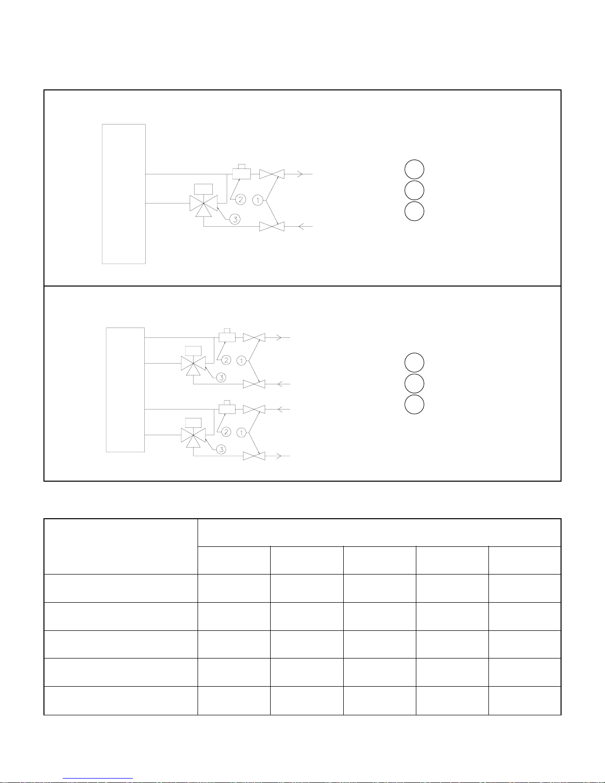
VALVE PACKAGES
VALVE PACKAGE 3-D (COOL ONLY)
F C U
F C U
OUT
IN
VALVE PACKAGE 4-D (COOL & HEAT)
OUT
IN
IN
OUT
Two gate shut off valves
1
One balancing valve
2
One 3-way motor valve
3
Four gate shut off valves
1
Two balancing valves
2
Two 3-way motor valves
3
DESCRIPTION
BLOWER WHEEL 800-707-58 800-707-57 & 58 800-707-57 & 58 800-707-57 & 58 800-707-57 & 58
BLOWER MOTOR 800-827-17 800-827-08 800-827-11 800-827-08 800-827-11
RETURN AIR FILTER 800-248-20 800-248-22 800-248-23 800-248-25 800-248-26
VALVE PACKAGE (3D), COOL ONLY 700-361-62 700-361-62 700-361-62 700-361-62 700-361-62
THERMOSTAT 800-646-20 800-646-20 800-646-20 800-646-20 800-646-20
NOTE: For 4D type valve package, order 2 x 3D valve packages.
PARTS LIST
MODEL NUMBER
VWL03 VWL04 VWL06 VWL08 VWL10
9
Page 11
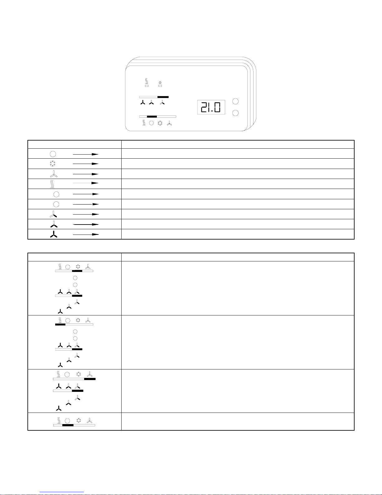
THERMOSTAT OPERATION & SPECIFICATION DATA
OPERATING INSTRUCTIONS
+
-
+
°C
-
FUNCTIONSYMBOL
OFF mode switch position
COOL mode switch position
FAN mode switch position
HEAT mode switch position
Temperature set button (increasing)
Temperature set button (decreasing)
LOW fan speed switch position
MEDIUM fan speed switch position
HIGH fan speed switch position
OPERATING PROCEDURE
FUNCTIONSWITCH POSITION
COOLING MODE
+
-
+
-
Notes:
1. Start-up display: When power is supplied to the thermostat, the LCD indicates a flashing display of the standard set point value. Press the (+) & (-) button at the same
time to change the display to ambient temperature.
2. Set point adjustment: When the (+) or (-) button is pressed, the thermostat assumes the temperature set point setting mode and the present set point is displayed. The
displayed set point can now be adjusted in 0.5K steps to the required value. After 3 seconds (approx.) the actual temperature will then be displayed.
- Position the switch S1 to COOL mode function.
- Set desired temperature setting by pressing the (+) or (-) button to increase or decrease the set
value displayed on the LCD of the thermostat .
- Fan speeds can be selected by positioning the switch S2 to:
LOW speed
MEDIUM speed
HIGH speed
HEATING MODE
- Position the switch S1 to HEAT mode function.
- Set desired temperature setting by pressing the (+) or (-) button to increase or decrease the set
value displayed on the LCD of the thermostat .
- Fan speeds can be selected by positioning the switch S2 to:
LOW speed
MEDIUM speed
HIGH speed
FAN MODE
- Position the switch S1 to FAN mode function.
- Fan speeds can be selected by positioning the switch S2 to:
LOW speed
MEDIUM speed
HIGH speed
UNIT OFF
- Position the switch S1 to OFF position to turn off the unit.
10
Page 12
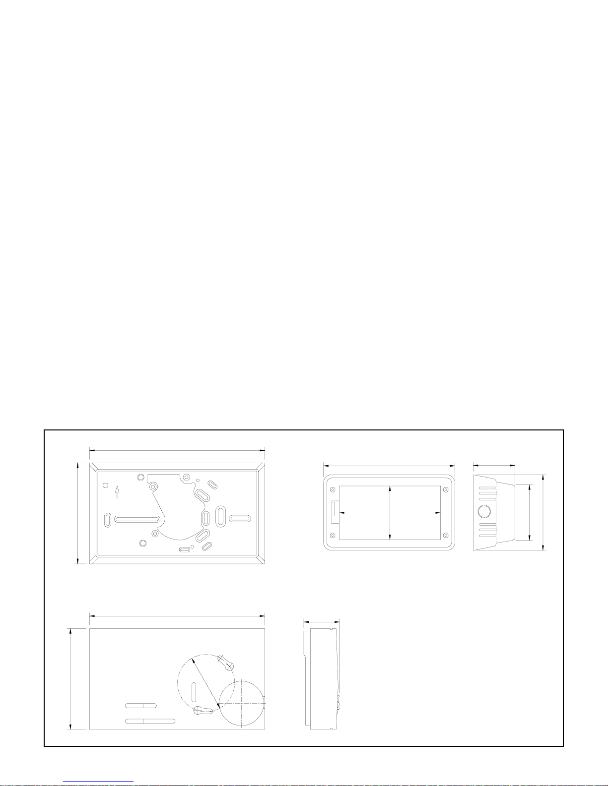
PRODUCT DATA
Part Number : 800-646-20
Switches : Fan speed high/med/low
Heat/Fan/Cool/Off
Outputs : Heat
Cool
Fan speed high/med/low
Inputs : Remote sensor (optional)
TECHNICAL DATA
Operating voltage : 230V + 10%; AC 50/60 Hz
Operating ambient : 0
Temperature range : 5
Selectivity of set value : 0.5K
Display range (actual value) : 0... + 40
Selectivity of actual value : 0.1K
Hysteresis : ~0.5K
Switching current at 250 VAC : 3 (2)A
Maximum fan current : 6 (3)A
Sensor system : NTC (in housing)
Switches : Heat/Off/Cool/Fan
Indicator lamps : Cool/Heat
0
C to 400C
0
C to 300C
0
C
Optional Remote Sensor 193720
3 Fan Speed
PHYSICAL DATA
Color : Polar white
Material : ABS plastic
Protection class : IP30 Plastic
Weight : 130 grams
Accessories : Base plate and screws
Option : Transparent wall mounted housing, lockable with ventilation slit.
DIMENSIONS
83
75
UP
OPEN
135.5
127
194
160
92
HOUSING PROTECTION (OPTIONAL)BASE PLATE
28.6
6
0
85
120
105
THERMOSTAT
NOTE: All dimensions are in mm.
11
Page 13

MAINTENANCE
Warning: Before you attend to any routine maintenance, make sure that the electrical power is disconnected.
- Avoid spilling any liquid on the thermostat
- Always allow for 1 to 2 minutes before activating different commands.
COIL CLEANING
Coil may be cleaned by removing and brushing between fins with a stiff wire brush. Brushing should be followed by
cleaning with vacuum cleaner. The coil may also be cleaned by using a high pressure air, if compressed air source is
available. It should be pointed out that if air filters are used and periodically cleaned, the coils will not be clogged up
prematurely.
DRAIN PIPE
Drain pipe should be checked before summer operation of unit. If it is clogged, steps should be taken to clear the debris
so that condensate will flow out easily. A standard pipe cleaner for 1/2" ID pipe may be used. Periodic checks of the drain
pipe should be taken during summer operation, as there is a possibility of it becoming clogged with dirt.
FILTER CLEANING
Remove access panel, slide filter out of filter rack, and clean as follows:
Tap filter on solid surface to dislodge heavy particles. Wash under stream of hot water. If filter has been put to exceptional
service, a mild solution of Sal-Soda, Tri-Sodium Phosphate or any other commercial solvent can be used. Set filter on
end with slots in frame down, which allows it to drain. Filters should dry thoroughly before reuse.
REPLACEMENT PARTS
When writing for replacement parts, refer to model number and serial number on the nameplate of the unit.
ROUTINE/PREVENTIVE MAINTENANCE
- Clean the thermostat box with a dry soft cloth.
- Remove the filter by a jet of air in the reverse return air direction.
- Inspect the condensate pipe for clogging.
12
 Loading...