

Page 1
INSTALLATION,
OPERATION
&
MAINTENANCE
MANUAL
SINGLE PACKAGED ROOF TOP AIR CONDITIONERS
'PT' SERIES
MODELS: PT036 - PT360
Part Number: 800-213-03
Page 2

INDEX
Contents Page
General
Model decoding ...................................................................................................................................................... 2
General statement .................................................................................................................................................. 3
Warranty ................................................................................................................................................................. 3
Safety issues .......................................................................................................................................................... 3
Inspection for damage ............................................................................................................................................ 3
Installation instructions
General................................................................................................................................................................... 4
Location of unit ....................................................................................................................................................... 4
Service clearance ................................................................................................................................................... 5
Rigging instructions ................................................................................................................................................ 5
Condensate drain connection................................................................................................................................. 6
Duct connection...................................................................................................................................................... 6
Electric heater ........................................................................................................................................................ 6
Unit weight & weight distribution ............................................................................................................................ 6
Unit dimensions ................................................................................................................................................. 7-11
Cable size............................................................................................................................................................. 12
Operation instructions
Start-up inspection & check list ............................................................................................................................ 12
Electrical data .................................................................................................................................................. 13-14
Performex controller, operation & functions .................................................................................................... 15-16
Crankcase heater ................................................................................................................................................. 16
Pump down control............................................................................................................................................... 16
Maintenance instructions
Airflow adjustment ................................................................................................................................................ 17
Crankcase heater ................................................................................................................................................. 17
Cleaning of coils & filters ...................................................................................................................................... 17
Belt tension testing procedure ......................................................................................................................... 17-18
Field wiring connections ....................................................................................................................................... 18
Preventive maintenance schedule ....................................................................................................................... 19
Trouble shooting chart ..................................................................................................................................... 20-21
Typical schematic wiring diagram....................................................................................................................22-29
Parts list ................................................................................................................................................................ 30
CONTINUING RESEARCH RESULTS IN STEADY IMPROVEMENTS.
THEREFORE, THESE SPECIFICATIONS ARE SUBJECT TO CHANGE WITHOUT NOTICE.
1
Page 3
15
UNIT
ACCESSORIES
MANUAL
DAMPER
N : STANDARD UNIT
C :FRESH AIR
15
UNIT
ACCESSORIES
MANUAL
DAMPER
N : STANDARD UNIT
C :FRESH AIR
14
OTHER
OPTIONS
13
PDS
OPTION
12
COIL
CONDENSER
11
COIL
EVAPORATOR
N : STANDARD UNIT
I : ANTI-ICE
OPTION
N : NO PDS
AL. FINS
J : IGT + ENHANCED
AL. FINS
J : IGT + ENHANCED
CONTACT
U :UVM
V : VOLT FREE
P : PDS OPTION
MHG. FINS
L : IGT + CORRU-
MHG. FINS
L : IGT + CORRU-
GATED CU. FINS
GATED CU. FINS
K :IGT + ENHANCED
K : IGT + ENHANCED
10
HEATER
OPTIONS
(kW/STAGE)
N : NO HEATER
A : 5/1
B : 6/1
C : 7.5/1
D : 10 /2
E : 12/2
9
DRIVE
OPTIONS
DRIVE
N : DIRECT
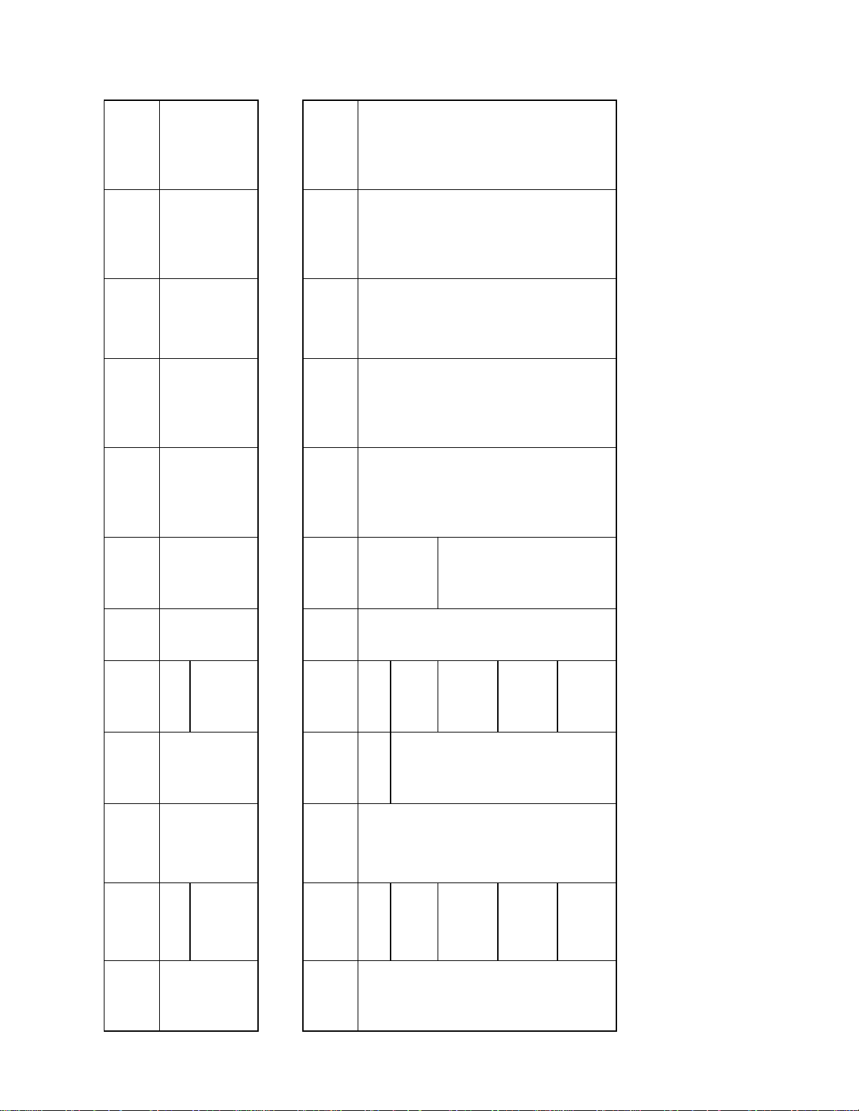
MODEL DECODING
14
OTHER
OPTIONS
13
PDS
OPTION
12
COIL
CONDENSER
11
COIL
EVAPORATOR
10
HEATER
OPTIONS
(kW/STAGE)
9
DRIVE
OPTIONS
N : STANDARD UNIT
I : ANTI-ICE
U :UVM
OPTION
N : NO PDS
P : PDS OPTION
AL. FINS
K : IGT + ENHANCED
AL. FINS
K : IGT + ENHANCED
A : 5/1*
B : 6/1*
C : 7.5/1
D : 10 /2
K : ALT. II
MHG. FINS
MHG. FINS
E : 12/2
F : 15 /2
J : IGT + ENHANCED
J : IGT + ENHANCED
N : NO HEATER
J : ALT. I
CONTACT
V : VOLT FREE
GATED CU. FINS
L : IGT + CORRU-
GATED CU. FINS
L : IGT + CORRU-
G : 20 /2
C : 7.5/1
D : 10 /2
E : 12/2
F : 15 /2
G : 20 /2
H : 25/2
J : 30/2**
MODELS: PT036 - PT060 (DIRECT DRIVE MOTOR)
8
MOTOR
BLOWER
7
REFRIGERA-
TION CIRCUIT
6
SUPPLY
( V-Ph-Hz )
ELECTRICAL
3, 4 & 5
NOMINAL
COOLING
CAPACITY
1& 2
BASIC
W : 0.75 HP ODP
S : SINGLE
L : 380/415-3-50
036
(MBH)
PT
W : 0.75 HP ODP
(4 WIRE)
048
UNIT
COOLINE
PACKAGED
Y : 1 HP ODP
060
MODELS: PT075 - PT360 (BELT DRIVEN MOTOR)
8
MOTOR
BLOWER
7
REFRIGERA-
TION CIRCUIT
6
SUPPLY
( V-Ph-Hz )
ELECTRICAL
3, 4 & 5
NOMINAL
COOLING
CAPACITY
1& 2
BASIC
C : 1.5 HP ODP
S : SINGLE
L : 380/415-3-50
075
(MBH)
PT
D : 2 HP ODP
D : 2 HP ODP
D :DUAL
(4 WIRE)
090
UNIT
COOLINE
PACKAGED
E : 3 HP ODP
F : 3 HP TEFC
100
120***
2
G : 5 HP ODP
H : 5 HP TEFC
J : 7.5 HP ODP
180
215
K : 7.5 HP TEFC
J : 7.5 HP ODP
K : 7.5 HP TEFC
240
300
L : 10 HP ODP
M : 10 HP TEFC
L : 10 HP ODP
360
M : 10 HP TEFC
N : 15 HP ODP
P : 15 HP TEFC
– Applicable for PT075 models only.
– Applicable for models PT180 & above only.
– 3 HP motor only available for PT120.
*
**
***
NOTE:
Page 4
GENERAL
GENERAL STATEMENT
This unit is from the PT series that was designed & built for the optimum performance. However, it is required that you become well
acquainted with good practices for the proper installation/operation/and maintenance procedures in order to ensure a safe trouble free
operation, year after year.
Please read through the whole manual contents before you attempt to install/operate/ and maintain the unit.
Most of the procedures described in this manual require certain skills and experience. The installation and other maintenance procedures
should be performed only by highly skilled and experienced technicians. The end user’s role should be limited to the cleaning of the
filter.
Please consult your nearest “COOLINE” representative for further information.
The PT units can be supplied, depending on the End User requirement, as the basic “Cool Only” version, or the “Heat & Cool” version
(with electric heater module).
WARRANTY
All of the PT series of Packaged Roof Top Units are covered by the standard warranty terms against any manufacturer defect. Should
you encounter any problem that falls under the warranty terms please contact your nearest “COOLINE” representative.
SAFETY ISSUES
There are three degrees of safety hazards that are identified throughout this manual as WARNING (where the situation will result in
personal injury), CAUTION (where personal injury might occur), and ATTENTION (where minor personal injury and/or property damage could happen). Please understand and respect those identifications.
WARNING: The PT units operate on a high voltage with moving parts (at high speed) which can lead to serious injuries and/
or damage to the unit. Never attempt to service the unit unless the main electrical power supply has been disconnected.
CAUTION: Extra care should be observed when installing, test running, adjusting, servicing, or maintaining the unit as the
hazard of explosion, fire, electrical shock, and potential personal injury and property damage are present.
When performing any task pertaining to the installation and maintenance of the unit, the skilled technician should observe all the
applicable safety measures (wear of safety helmet, boots, gloves, and goggles. Use of proper handling materials for brazing and use
of wet cloth for quenching. A fire extinguisher should be easily accessible etc.). He should also read all the instructions and information
in this Manual prior to attempting to perform any installation or servicing of the unit.
All applicable local codes should also be observed.
INSPECTION FOR DAMAGE
The unit should be carefully inspected visually for any sign of physical damage due to mishandling. Whenever a damage is detected,
please indicate it on the corresponding delivery note before you sign it and inform your nearest “COOLINE” office.
3
Page 5
INSTALLATION INSTRUCTIONS
GENERAL
These units are shipped completely assembled, charged, and wired. They do not require any field installation of refrigerant tubing.
Units require external power, thermostat wiring, condensate drain piping and ducting as applicable.
Size of unit for an installation should be based on a heat gain calculation made according to applicable standards. Units must also be
installed in accordance with regulations of the "National Fire Protection Association" and local electrical codes. Where local regulations
conflicts with the instructions in this manual, installer should adhere to local standards.
Prepare your concrete pad or steel stand based on the corresponding dimensions. Remove shipping protective covers and wooden
crating and lift unit from base and place in position with suitable rubber vibration isolators.
All field installed accessories are to be installed by the customer with necessary reinforcements as required.
LOCATION OF UNIT
When selecting the location for the unit, the following points should be kept in mind:
1. Provisions for a concrete pad or steel stand base.
2. That the terrain allows for drainage away from the unit.
3. If the unit is to be roof mounted, inspect the roof for load bearing capacity. The roof should have sufficient structural strength to
carry the weight of the unit.
4. Install unit on vibration isolation pads, i.e. on rubber mounting pads.
5. Availability of electric power.
6. To position the unit for unrestricted air circulation of the condenser air inlet and to prevent any possibility of air recirculation from the
condenser fan discharge air (see figure on next page).
7. Check minimum clearances required for your unit, with regard to walls, or other obstructions (see figure on next page).
8. Air cooled equipment should not be installed under low structural overhangs which can cause condenser air recirculation or
restriction. Observe minimum of clearance (see figure on next page).
9. Care should be taken to prevent air from other sources from entering condenser, if this air is at a high temperature.
10. Level the unit on its final location and be sure that the levelling tolerance is ±5 mm per linear meter in any direction.
CAUTION: Do not install the unit as indoor unit, install it in an open area, and unit air inlets must not be located near exhaust
vents or other source of contaminated air.
4
Page 6
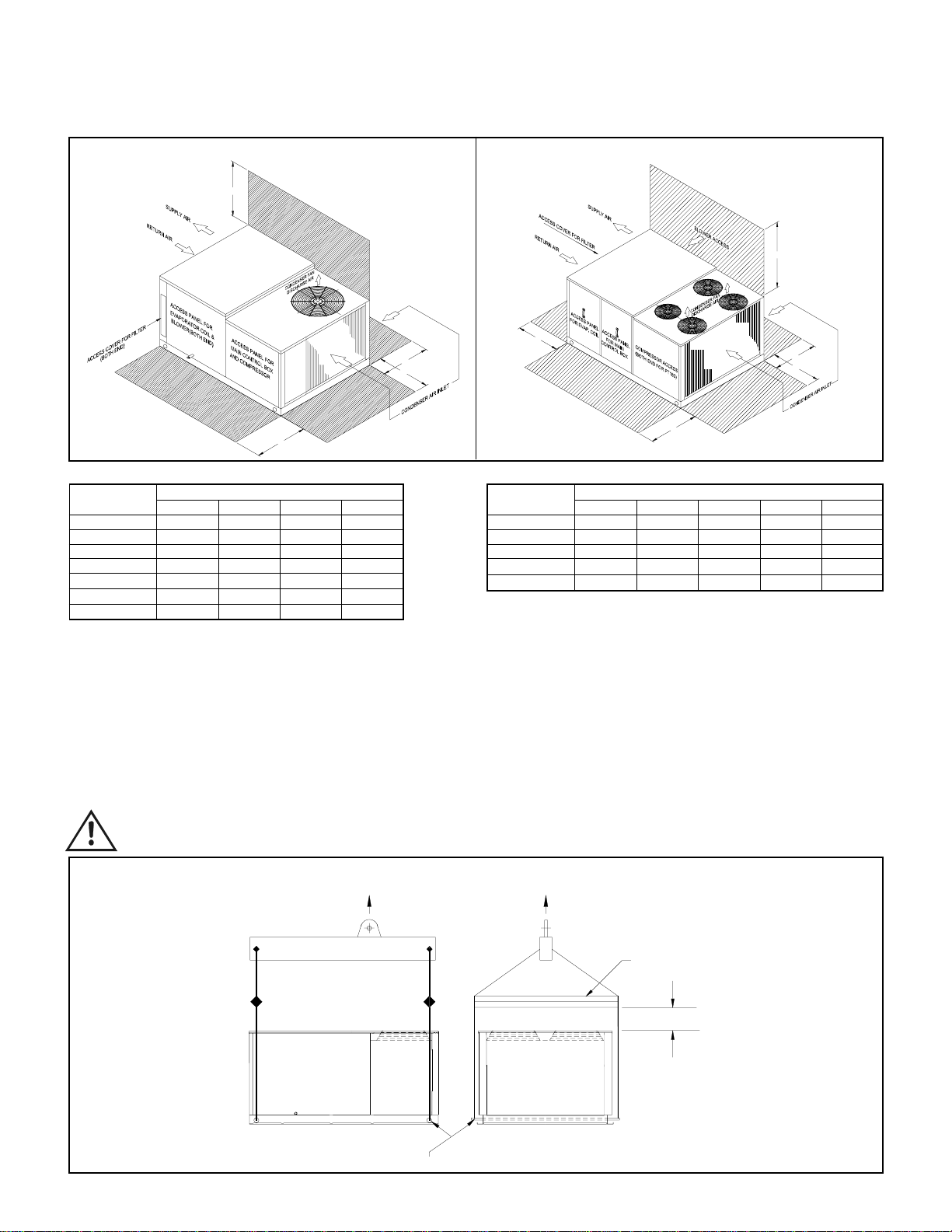
SERVICE CLEARANCE
MODELS: PT036 - PT120
D
C
A
B
NOTE: All dimensions are in cm.
MODEL DIMENSIONS
NUMBER A B C D
PT036 85 105 85 150
PT048 85 105 85 150
PT060 85 105 85 150
PT075 90 105 90 200
PT090 90 105 90 200
PT100 90 105 90 200
PT120 90 105 90 200
A :Clearance dimension from condenser coil
B : Clearance dimension from compressor, control box, blower, evaporator coil & filter
C : Clearance dimension from condenser coil & filter
D : Clearance dimension over the condenser fan
MODELS: PT180 - PT360
D
E
C
A
B
NOTE: Only two condenser fans for models PT180 - PT240.
MODEL DIMENSIONS
NUMBER A B C D E
PT180 120 120 115 250 90
PT215 120 120 115 250 90
PT240 120 120 115 250 90
PT300 120 120 115 250 90
PT360 120 120 115 250 90
A : Clearance dimension from condenser coil
B : Clearance dimension from compressor, control box & evaporator coil
C : Clearance dimension from condenser coil & blower
D : Clearance dimension over the condenser fan
E : Clearance dimension from filter access panel
RIGGING INSTRUCTIONS
ATTENTION TO RIGGERS
• Insert 2" nominal pipe through holes in the base rail as shown in the figure below for slings.
• Holes in base rail are centered around the unit center of gravity.
• Use wooden pallet or spreader bar when rigging, to prevent the slings from damaging the unit.
• Rollers may be used to move the unit on the roof or ground.
CAUTION: All panels should be in place when rigging.
MODELS: PT036 - PT360
LIFT
COMPRESSOR
END
NOMINAL PIPE THRU UNIT FOR SLINGS TO AVOID BASE DAMAGE.
LIFT
SPREADER BAR
PROPER CLEARANCE TO BE
PROVIDED.
Note:
1 .PIPE DIA 1 1/2" FOR PT036 TO PT075 MODELS
2. PIPE DIA 2" FOR PT090 TO PT360 MODELS
5
Page 7
CONDENSATE DRAIN CONNECTION
• Use standard PVC pipe with NPT connection for the condensate drain. Provide a 'P' trap immediately at the condensate drain connection.
• Piping has to be sloped away from the unit.
• Remember to remove the drain hole plug before operating the unit. Avoid bends & elbows.
DUCT CONNECTION
The units can be connected to the ducting in horizontal configuration. Connect ducting using flexible duct connection. The duct should
be properly designed and the drive package should match the required CFM & corresponding external static pressure.
ATTENTION: Avoid abrupt changes in size and/or direction of duct to ensure proper unit performance.
ELECTRIC HEATERS
Electric heater kit is installed in the unit at the supply air opening space.
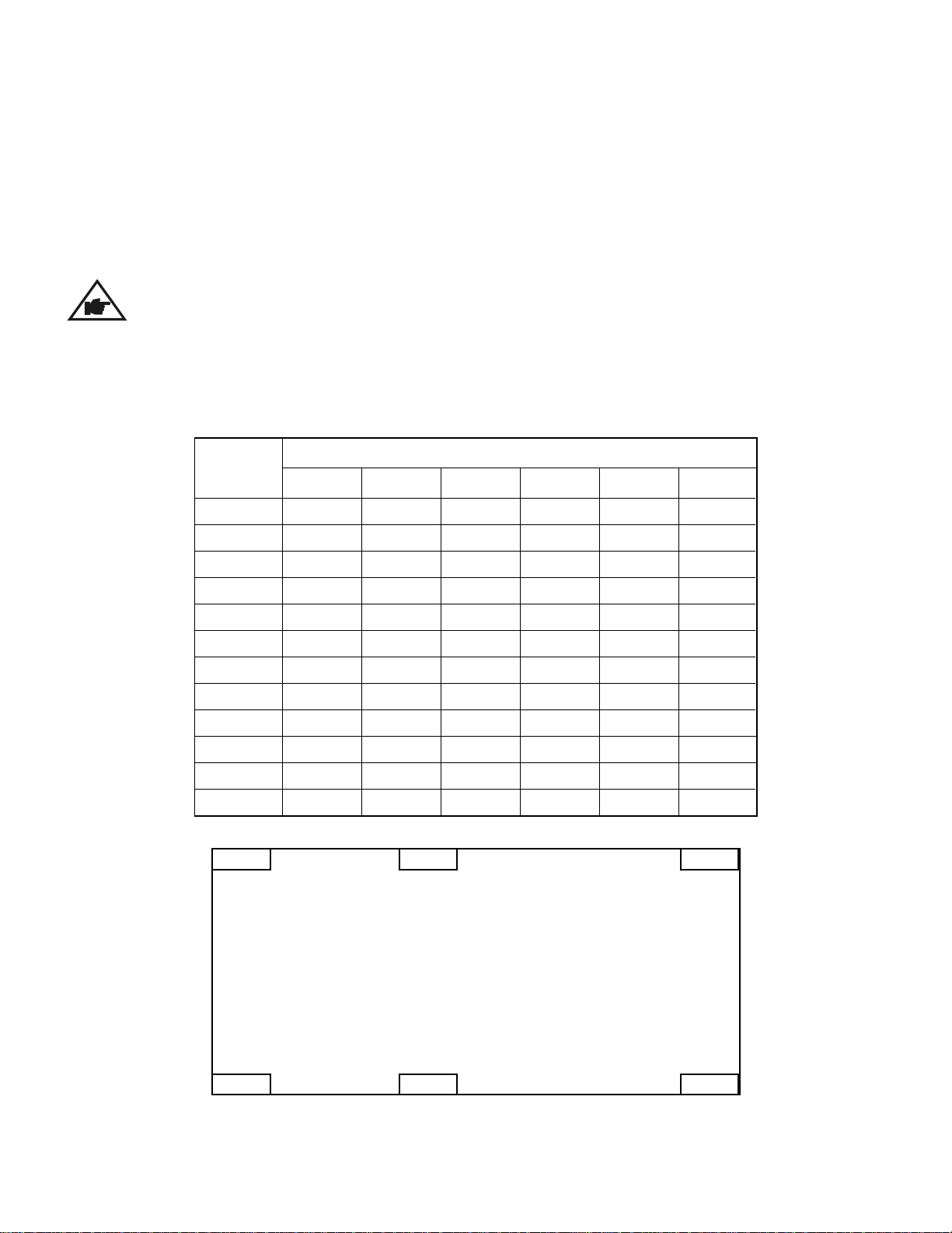
UNIT WEIGHT & WEIGHT DISTRIBUTION
MODEL
NUMBER
PT036
PT048
PT060
PT075
PT090
PT100
PT120
PT180
PT215
PT240
PT300
PT360
JP K
JKML
67
72
76
86
116
134
135
155
182
186
226
256
36
41
45
52
92
91
91
99
89
94
130
145
WEIGHTS (Kg.)
51
57
62
70
95
98
98
152
94
98
202
216
34
39
42
45
73
73
73
85
101
105
148
151
PQ
-
-
-
-
-
-
-
108
177
181
221
249
-
-
-
-
-
-
-
105
103
107
158
175
CONDENSER SECTION
MQ L
=
=
SUPPL Y AIR/
RETURN AIR
6
Page 8
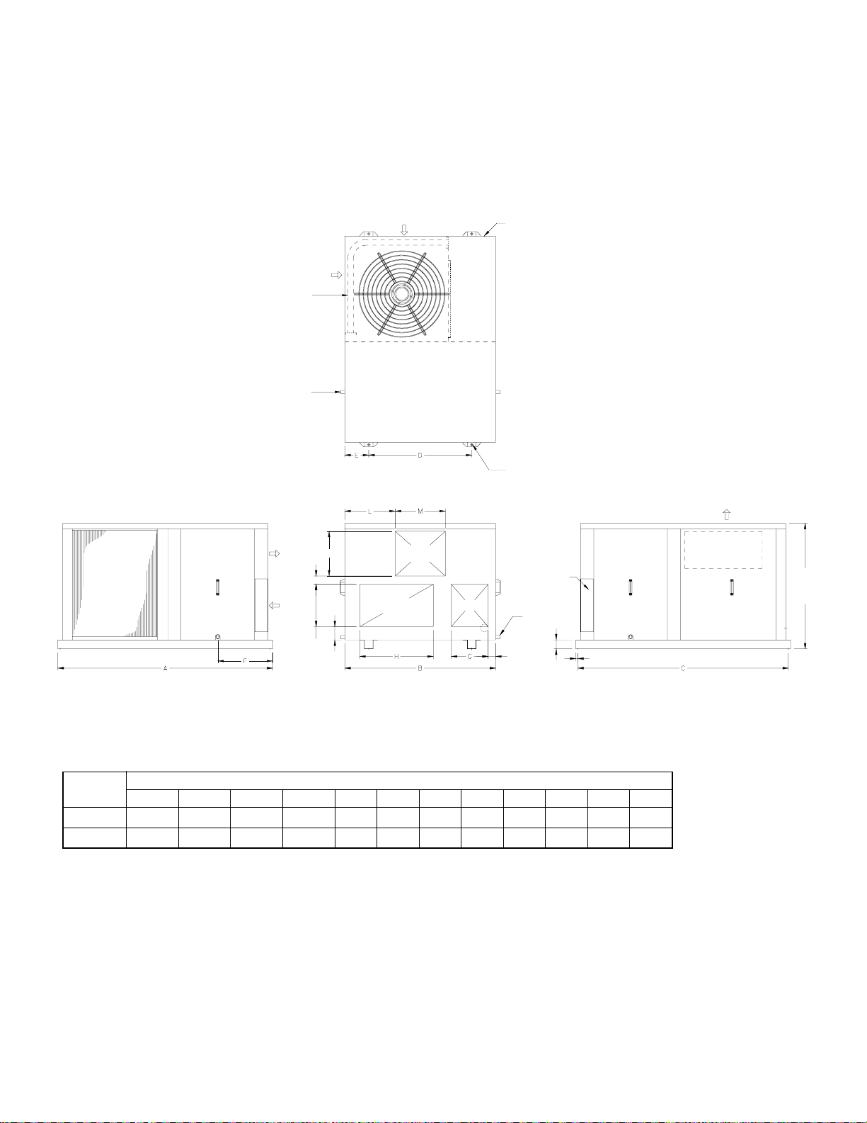
UNIT DIMENSIONS
PT036 - PT075
CONDENSER COIL
CONDENSER COIL
CONDENSATE DRAIN OUTLET [BOTH ENDS]
SUPPLY AIR
RETURN AIR
AIR IN
J
AIR IN
COMPARTMENT
COMPRESSOR/CONTROL
TOP VIEW
SUPPLY
RETURN A IR
OPENING
AIR
OPENING
FRESH AIR
OPENING
K
POWER SUPPLY INLET
MOUNTING HOLES Ø
13 [0.5] [ 4 EACH]
FILTER ACCESS
PANEL [BOTH ENDS]
DRAIN OUTLET
[BOTH ENDS]
ACCESS PANEL
FOR BLOWER
AND MOTOR
AIR OUT
COMPRESSOR/CONTROLS
ACCESS PANEL
850 [33.46]
MODEL
51 [2.00]
286 [11.27]
SIDE VIEW
90 [3.53]
FRONT VIEW
DIMENSIONS
ABCDEFGHJKLM
15 [0.59]
61 [2.41]
PT036 - PT060 1460(57.48) 1025(40.35) 1430(56.3) 700(27.56) 163(6.42) 373(14.68) 250(9.84) 500(19.69) 57(2.24) 304(11.96) 343(13.49) 340(13.39)
PT075 1775(69.88) 1150(45.28) 1745(68.7) 800(31.5) 175(6.89) 480(18.9) 325(12.8) 672(26.46) 80(3.15) 280(11.02) 275(10.83) 600(23.62)
NOTE:
1. All dimensions are in mm (dimensions in brackets are in inches).
2. Service clearance should be 1200mm (4 feet) on all sides.
SIDE VIEW
7
Page 9
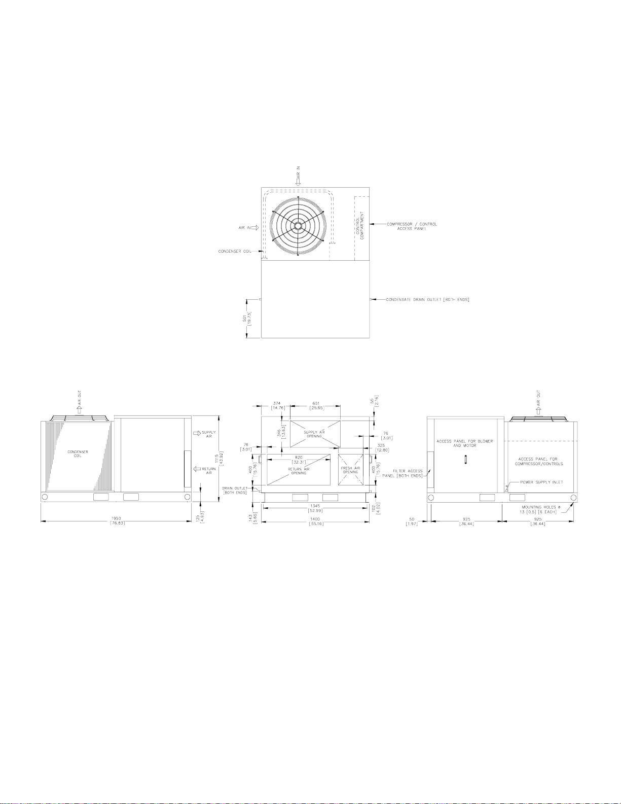
UNIT DIMENSIONS
PT090 - PT120
TOP VIEW
SIDE VIEW
NOTE:
1. All dimensions are in mm (dimensions in brackets are in inches).
2. Service clearance should be 1200mm (4 feet) on all sides.
SIDE VIEWFRONT VIEW
8
Page 10
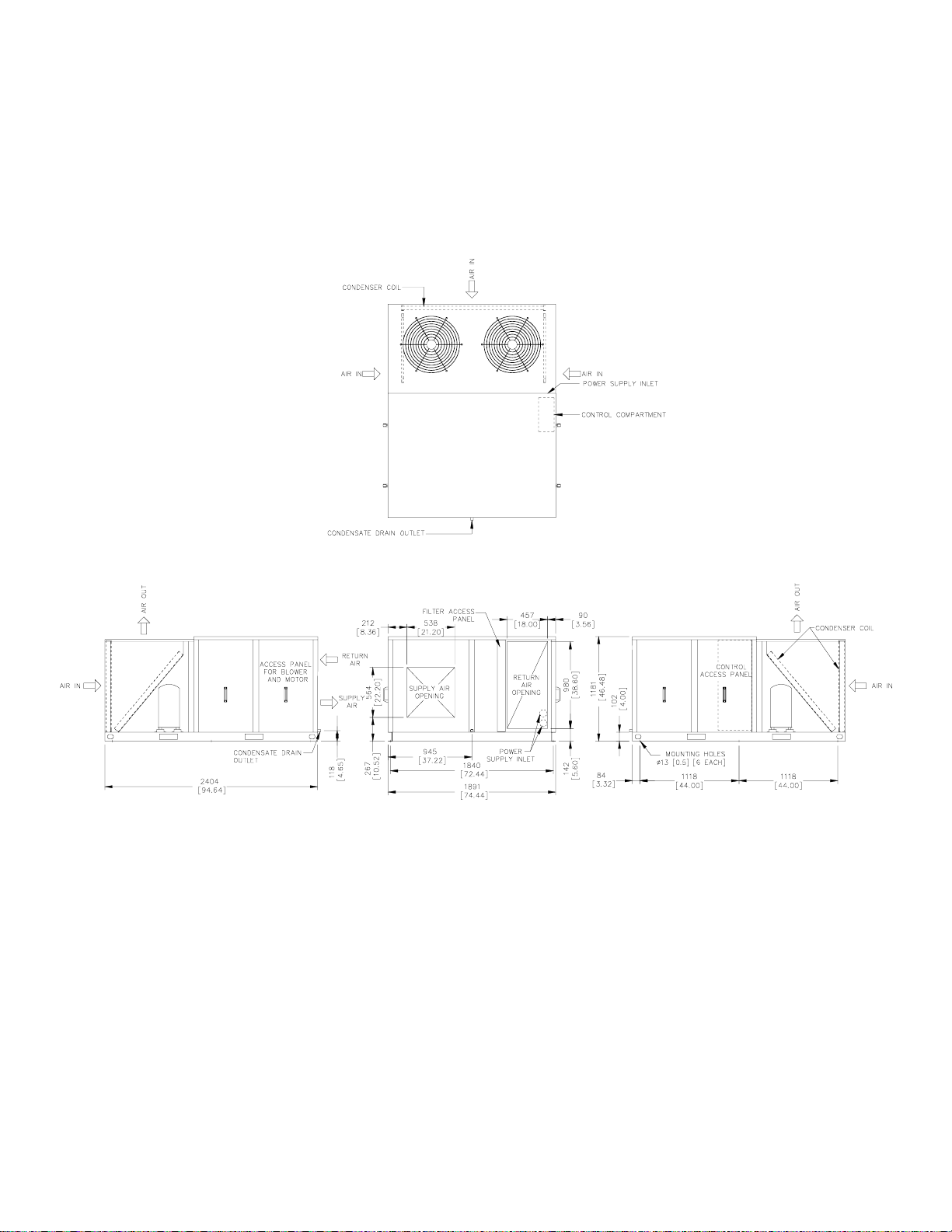
UNIT DIMENSIONS
PT180
TOP VIEW
SIDE VIEW SIDE VIEWFRONT VIEW
NOTE:
1. All dimensions are in mm (dimensions in brackets are in inches).
2. Service clearance should be 1200mm (4 feet) on all sides.
9
Page 11
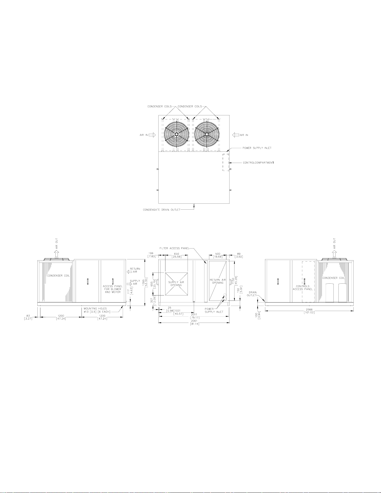
UNIT DIMENSIONS
PT215 - PT240
TOP VIEW
SIDE VIEW SIDE VIEW
NOTE:
1. All dimensions are in mm (dimensions in brackets are in inches).
2. Service clearance should be 1200mm (4 feet) on all sides.
FRONT VIEW
10
Page 12
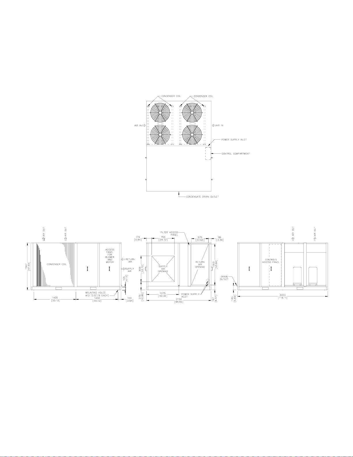
UNIT DIMENSIONS
PT300 - PT360
TOP VIEW
SIDE VIEW
NOTE:
1. All dimensions are in mm (dimensions in brackets are in inches).
2. Service clearance should be 1200mm (4 feet) on all sides.
FRONT VIEW
11
SIDE VIEW
Page 13
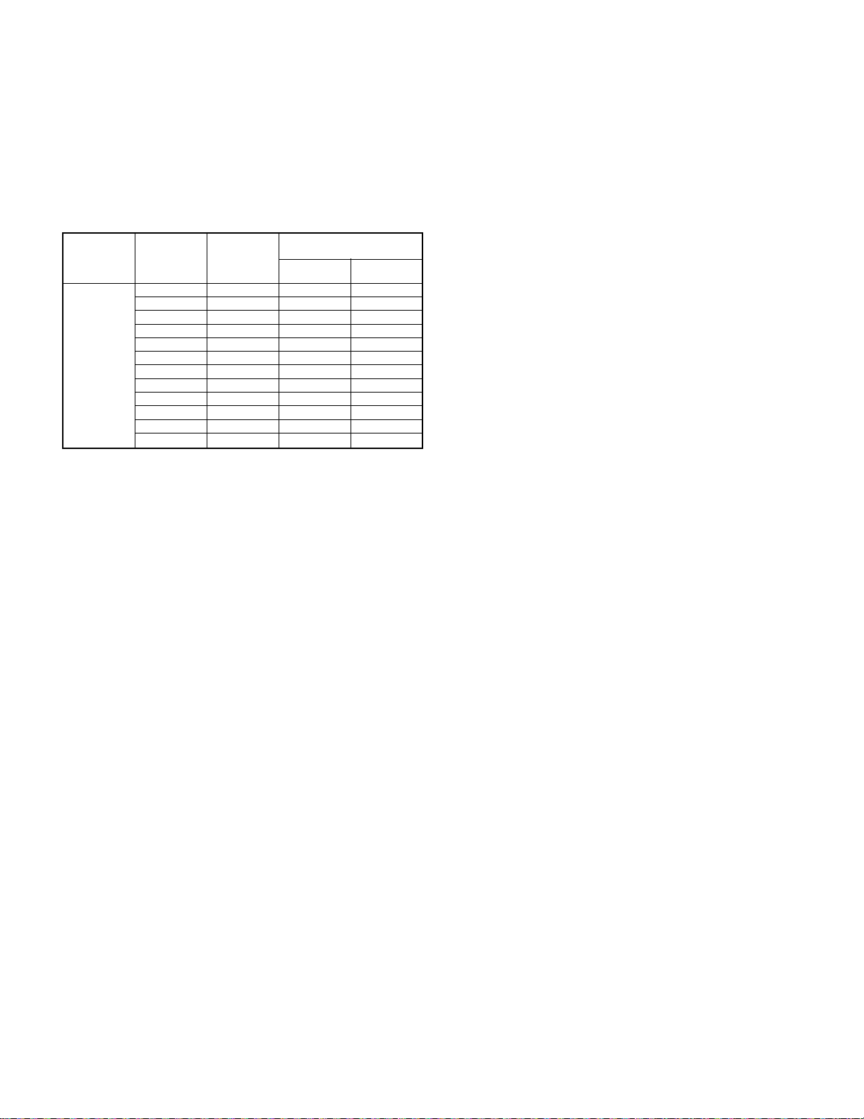
CABLE SIZE
• All wiring should be in accordance with local standards.
• Before making any connection, check the electric power supply, it must have the same characteristics as what is displayed in the
nameplate.
• For selecting cable size, refer to wire ampacity table at different MCA (Minimum Circuit Amps) provided in unit electrical data, which
is listed as a guideline (see table below).
• Wiring connection to the unit must have suitable insulation of a minimum temperature of 60
0
C.
POWER
SUPPLY
380/415-3-50
(4 wire)
LEGEND: MCA - Minimum Circuit Amps
MODEL
No.
PT036 15.2 14 2.5
PT048 20.8 12 4
PT060 22.1 12 4
PT075 20.9 12 4
PT090 25.1 10 6
PT100 30 10 6
PT120 33.6 8 10
PT180 54.8 6 16
PT215 60 6 16
PT240 65 4 25
PT300 80.3 3 26.6
PT360 92.8 2 33.6
MCA
CONDUCTOR SIZE
AWG
METRIC
MM
2
Notes: 1. Customer is to select cable size also with cross reference as per cable manufacturer data for voltage reduction per unit
length. The above cable ampacity table is for guidance only.
2. The selected cables for specified units is as per following characteristics:
a. Unit without electric heaters.
b. Any extra electrical accessories shall add to MCA rate, for more information, refer to unit electrical tables in the catalog.
OPERATION INSTRUCTIONS
START-UP INSPECTION & CHECK LIST
After the installation is completed in all respect, the following points should be covered before the system is switched on for operation.
1. Check unit location as per installation instructions.
2. Make sure all electrical fasteners/connections are tight and clean.
3. All controls are set according to manufacturer's instructions (low & high pressure switch, pump down solenoid, etc...)
4. Make sure all valves are open (compressor suction & discharge service valves, liquid line, etc.).
5. Follow all the instructions from the warning tags and stickers.
6. Check if condenser & blower fan are free to turn without wobbling.
7. Remove straps & wooden pieces that holds the compressor in place during transportation.
8. Compressor crankcase heater should be energized for 24 hours (special attention should be taken to disable compressor contactor
before energizing the unit.
9. Expansion valve bulb is strapped properly at correct location (applicable for PT075 - PT360 only).
10. Circuit breaker/fused disconnect switch.
11. Blower fan belt is properly tightened and pulleys are properly aligned (applicable for PT075 - PT360 only).
12. All refrigerant service valve caps are installed.
13. All piping, piping insulation and piping supports are properly installed.
14. Thermostat is the right one and installed properly.
15. Connect the manifold gauge to suction & discharge line service valves. Prepare recommended instruments for checking Voltage,
Amps, RPM, CFM, static pressure, etc.
16. Start the blower fan and condenser fan. Check the amperage against the nameplate ampere.
17. Start the compressor & observe the compressor discharge and suction pressures. If not within system design limits, determine
why & take corrective action.
12
Page 14
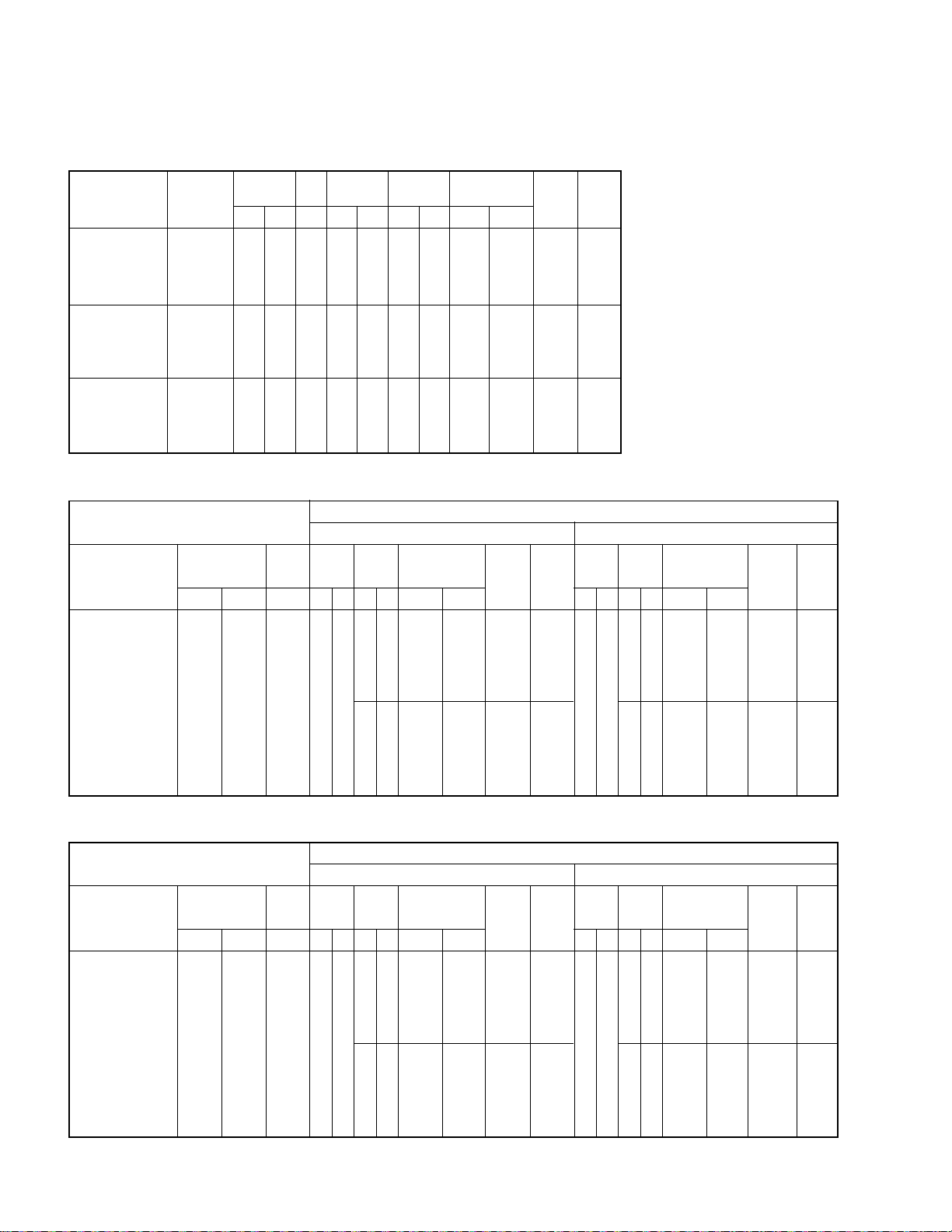
MODELS: PT036 - PT060
MODEL
NUMBER
PT036
PT048
PT060
POWER
SUPPLY
(V-Ph-Hz)
380/415-3-50 342 457 2.3 5.9 42 0.75 5.5
(4 WIRE)
380/415-3-50 342 457 2.3 10.4 55 0.75 5.5
(4 WIRE)
380/415-3-50 342 457 2.3 9.6 65 1 7.8
(4 WIRE)
VOLTAGE
MIN. MAX. FLA RLA LRA HP FLA kW FLA
MODELS: PT075 & PT090
DESCRIPTION
POWER
SUPPLY
(V-Ph-Hz)
VOLTAGE
RANGE
342 457 2.3
RANGE
FM
(each)
FLAMax.Min.
(1.9 FOR
PT090)
ELECTRICAL DATA
FM COMPRES-
SOR
COMPR-
ESSOR
(each)
RLA LRA HP FLA
BM
1.523.4
101 12380/415-3-50 (4 WIRE)
BLOWER
MOTOR
ELECTRIC
HEATER
– – 15.2 20
5/6 7.6/9.1 16.4/18.3 20/20
7.5/10* 11.4/15.2 21.1/25.9 25/30
12* 18.2 29.6 30
– – 20.8 30
5/6 7.6/9.1 20.8/20.8 30/30
7.5/10* 11.4/15.2 21.1/25.9 35/30
12* 18.2 29.6 30
– – 22.1 30
5/6 7.6/9.1 22.1/22.1 30/30
7.5/10* 11.4/15.2 24/28.8 30/30
12* 18.2 32.5 35
MCA
MOCP
MODEL NUMBER
PT075 PT090
ELECTRIC
HEATER
Nom. kW
7.5/10* 11.4/15.2 20.7/23.3 30/30
12*/15* 18.2/22.8 27/32.8 30/35
3.6
7.5/10* 11.4/15.2 20.9/23.5 30/30
12*/15* 18.2/22.8 27.3/33 30/35
FLA
– – 20.7 30
5/6 7.6/9.1 20.7/20.7 30/30
– – 20.9 30
5/6 7.6/9.1 20.9/20.9 30/30
MOCPMCA
COMPR-
ESSOR
(each)
RLA LRA HP FLA
50
8.2
LEGEND:
FLA - Full Load Amps
HP - Horse Power
BM - Blower Motor
LRA - Locked Rotor Amps
RLA - Rated Load Amps
MCA - Minimum Circuit Amps
MOCP - Maximum Over Current Protection
FM - Fan Motor (Condenser)
*Combination of heater modules
BM
233.6
ELECTRIC
HEATER
Nom. kW
7.5/10* 11.4/15.2 24/24 30/30
12*/15* 18.2/22.8 27.3/33 30/35
4.7
7.5/10* 11.4/15.2 25.1/25.1 30/30
12*/15* 18.2/22.8 28.6/34.4 30/35
FLA
– – 24 30
5/6 7.6/9.1 24/24 30/30
20* 30.4 42.5 45
– – 25.1 30
5/6 7.6/9.1 25.1/25.1 30/30
20* 30.4 43.9 45
MOCPMCA
MODELS: PT100 & PT120
DESCRIPTION
POWER
SUPPLY
(V-Ph-Hz)
VOLTAGE
RANGE
342 457 1.9
FM
(each)
FLAMax.Min.
COMPR-
ESSOR
(each)
RLA LRA HP FLA
BM
233.6
55 10.4380/415-3-50 (4 WIRE)
4.7
MODEL NUMBER
PT100 PT120
ELECTRIC
HEATER
Nom. kW
7.5/10 11.4/15.2 28.9/28.9 35/35
10*/12* 15.2/18.2 28.9/28.9 35/35
15*/20* 22.8/30.4 33/42.5 35/45
7.5/10 11.4/15.2 30/30 40/40
10*/12* 15.2/18.2 30/30 40/40
15*/20* 22.8/30.4 34.4/43.9 40/45
FLA
– – 28.9 35
– – 30 40
MOCPMCA
COMPR-
ESSOR
(each)
RLA LRA HP FLA
10
BM
354.7
74
9.2
13
ELECTRIC
HEATER
Nom. kW
10*/12* 15.2/18.2 29.1/29.1 35/35
15*/20* 22.8/30.4 34.4/43.9 35/45
10*/12* 15.2/18.2 33.6/34.3 40/40
15*/20* 22.8/30.4 40/49.5 40/50
FLA
– – 29.1 35
7.5/10 11.4/15.2 29.1/29.1 35/35
25* 38 53.4 60
– – 33.6 40
7.5/10 11.4/15.2 33.6/33.6 40/40
25* 38 59 60
MOCPMCA
Page 15
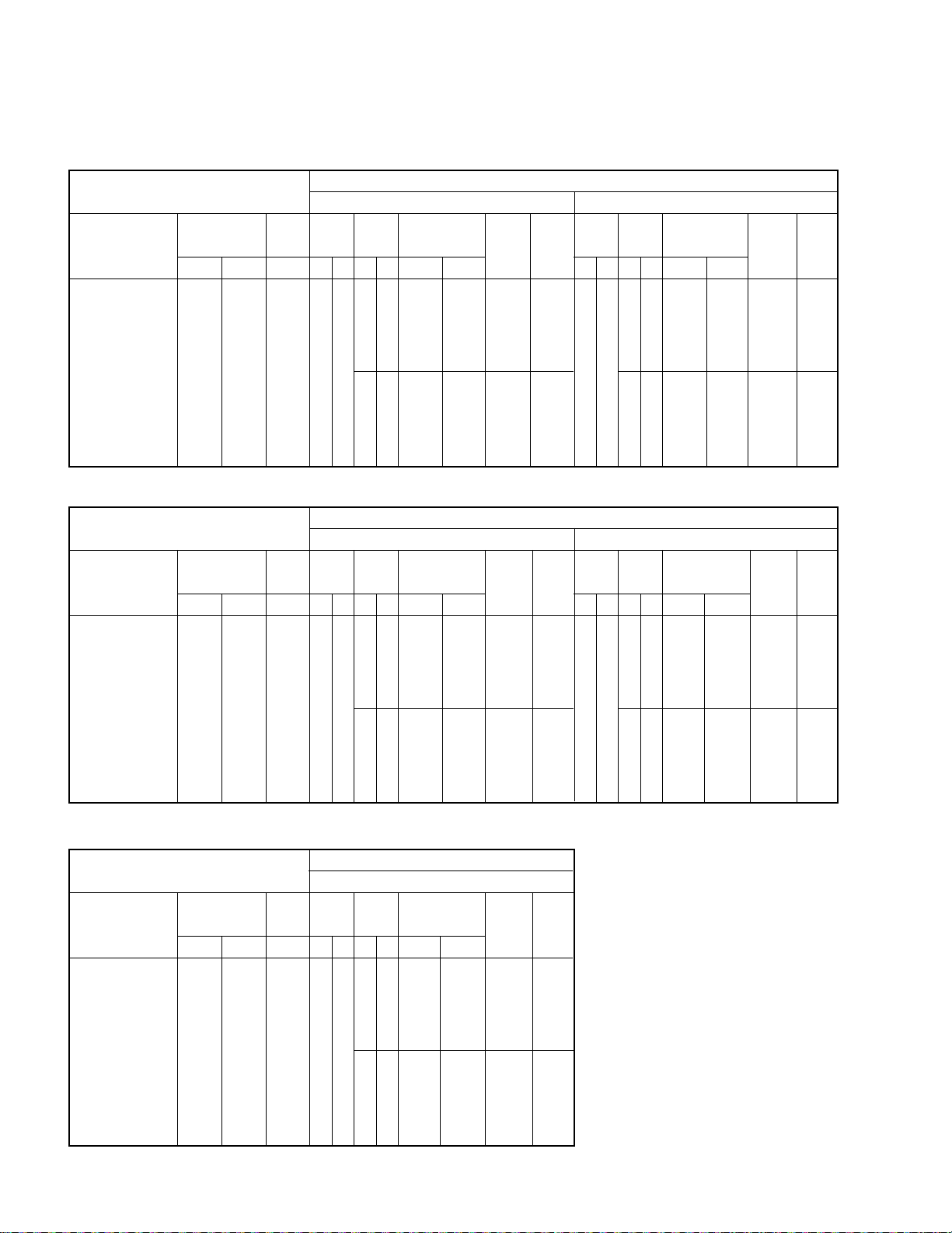
ELECTRICAL DATA
MODELS: PT180 & PT215
DESCRIPTION
POWER
SUPPLY
(V-Ph-Hz)
380/415-3-50 (4 WIRE)
VOLTAGE
RANGE
342 457 1.9
MODELS: PT240 & PT300
DESCRIPTION
POWER
SUPPLY
(V-Ph-Hz)
VOLTAGE
RANGE
342 457 1.9
FM
(each)
FLAMax.Min.
FM
(each)
FLAMax.Min.
COMPR-
ESSOR
(each)
RLA LRA HP FLA
17.3
&
16.4
COMPR-
ESSOR
(each)
RLA LRA HP FLA
BM
5
9.2
111
&
95
7.5
13
BM
7.51013
118 19.6380/415-3-50 (4 WIRE)
15.1
MODEL NUMBER
PT180 PT215
ELECTRIC
HEATER
Nom. kW
7.5/10 11.4/15.2 51/51 60/60
10*/12* 15.2/18.2 51/51 60/60
15*/20* 22.8/30.4 51/51 60/60
25*/30* 38/45.6 59/68.5 60/70
7.5/10 11.4/15.2 54.8/54.8 70/70
10*/12* 15.2/18.2 54.8/54.8 70/70
15*/20* 22.8/30.4 54.8/54.8 70/70
25*/30* 38/45.6 63.8/73.3 70/80
FLA
– – 51 60
– – 54.8 70
MOCPMCA
COMPR-
ESSOR
(each)
RLA LRA HP FLA
19.2
125
7.5
BM
5
9.2
13
MODEL NUMBER
PT240 PT300
ELECTRIC
HEATER
Nom. kW
7.5/10 11.4/15.2 60.9/60.9 80/80
10*/12* 15.2/18.2 60.9/60.9 80/80
15*/20* 22.8/30.4 60.9/60.9 80/80
25*/30* 38/45.6 63.8/73.3 80/80
7.5/10 11.4/15.2 63/63 80/80
10*/12* 15.2/18.2 63/63 80/80
15*/20* 22.8/30.4 63/63 80/80
25*/30* 38/45.6 66.4/75.9 80/80
FLA
– – 60.9 80
– – 63 80
MOCPMCA
COMPR-
ESSOR
(each)
RLA LRA HP FLA
25.6
BM
7.51013
167
15.1
ELECTRIC
HEATER
Nom. kW
10*/12* 15.2/18.2 56.2/56.2 70/70
15*/20* 22.8/30.4 56.2/56.2 70/70
25*/30* 38/45.6 59/68.5 70/70
10*/12* 15.2/18.2 60/60 70/70
15*/20* 22.8/30.4 60/60 70/70
25*/30* 38/45.6 63.8/73.3 70/80
Nom. kW
10*/12* 15.2/18.2 78.2/78.2 100/100
15*/20* 22.8/30.4 78.2/78.2 100/100
25*/30* 38/45.6 78.2/78.2 100/100
35*/40* 53.2/60.8 82.8/92.3 100/100
10*/12* 15.2/18.2 80.3/80.3 100/100
15*/20* 22.8/30.4 80.3/80.3 100/100
25*/30* 38/45.6 80.3/80.3 100/100
35*/40* 53.2/60.8 85.4/94.9 100/100
FLA
– – 56.2 70
7.5/10 11.4/15.2 56.2/56.2 70/70
– – 60 70
7.5/10 11.4/15.2 60/60 7070
ELECTRIC
HEATER
FLA
– – 78.2 100
– – 80.3 100
MOCPMCA
MOCPMCA
MODEL: PT360
DESCRIPTION
POWER
SUPPLY
(V-Ph-Hz)
380/415-3-50 (4 WIRE)
VOLTAGE
RANGE
342 457 1.9
FM
(each)
FLAMax.Min.
COMPR-
ESSOR
(each)
RLA LRA HP FLA
BM
1015 15.1
19827.8
22.6
MODEL NUMBER
PT360
ELECTRIC
HEATER
Nom. kW
10*/12* 15.2/18.2 85.3/85.3 110/110
15*/20* 22.8/30.4 85.3/85.3 110/110
25*/30* 38/45.6 85.3/85.3 110/110
35*/40* 53.2/60.8 85.4/94.9 110/110
10*/12* 15.2/18.2 92.8/92.8 110/110
15*/20* 22.8/30.4 92.8/92.8 110/110
25*/30* 38/45.6 92.8/92.8 110/110
35*/40* 53.2/60.8 94.8/104.3 110/110
FLA
– – 85.3 110
– – 92.8 110
MOCPMCA
14
LEGEND:
FLA - Full Load Amps
HP - Horse Power
BM - Blower Motor
LRA - Locked Rotor Amps
RLA - Rated Load Amps
MCA - Minimum Circuit Amps
MOCP - Maximum Over Current Protection
FM - Fan Motor (Condenser)
*Combination of heater modules
Page 16

Performex-1TM CONTROLLER : OPERATION & FUNCTIONS
The COOLINE Packaged units are provided with technologically advanced new PerformexTM Controller Microprocessor Based
Electronic Control Board, incorporating the following benefits and features:
- COMPLETE UNIT CONTROL: Provides complete unit control for heating and cooling application whether single
stage or two stage utilizing the input from sensor that measure temperatures during unit operation.
- COMPRESSOR LOCKOUT: If any of the unit’s safety controls trip due to abnormal conditions the Electronic
Control locks out the compressor, preventing restart, unless attended by qualified service technicians. The unit can
be re-started only by reset the thermostat after ensuring safe system conditions.
- LEAD LAG OPERATION: The unit electronic controls automatically alternate lead and lag the compressors for
even operation. Compressor #1 can be set always lead as an option.
- ANTI-RECYCLE TIMER: For compressor safety in case of accidental manual reset or immediate recycling of
thermostat due to load demand. This considerably improves compressor life.
- PUMP DOWN OPTION: In units equipped with pump down system the time delay creates the required time gap between
the solenoid opening and compressor start to equalize the pressure in the system prior to compressor start up.
- AUTO/MANUAL RESET OF THE ALARM SIGNALS.
- FULL CONTROL OF THE INDOOR FAN: Fan operation can be selected either to run continuously or stage with
the compressor/heaters.
- PROTECTION: The PerformexTM Controller will provide the following protection:
1. Compressor high pressure protection (option)
2. Compressor low pressure protection
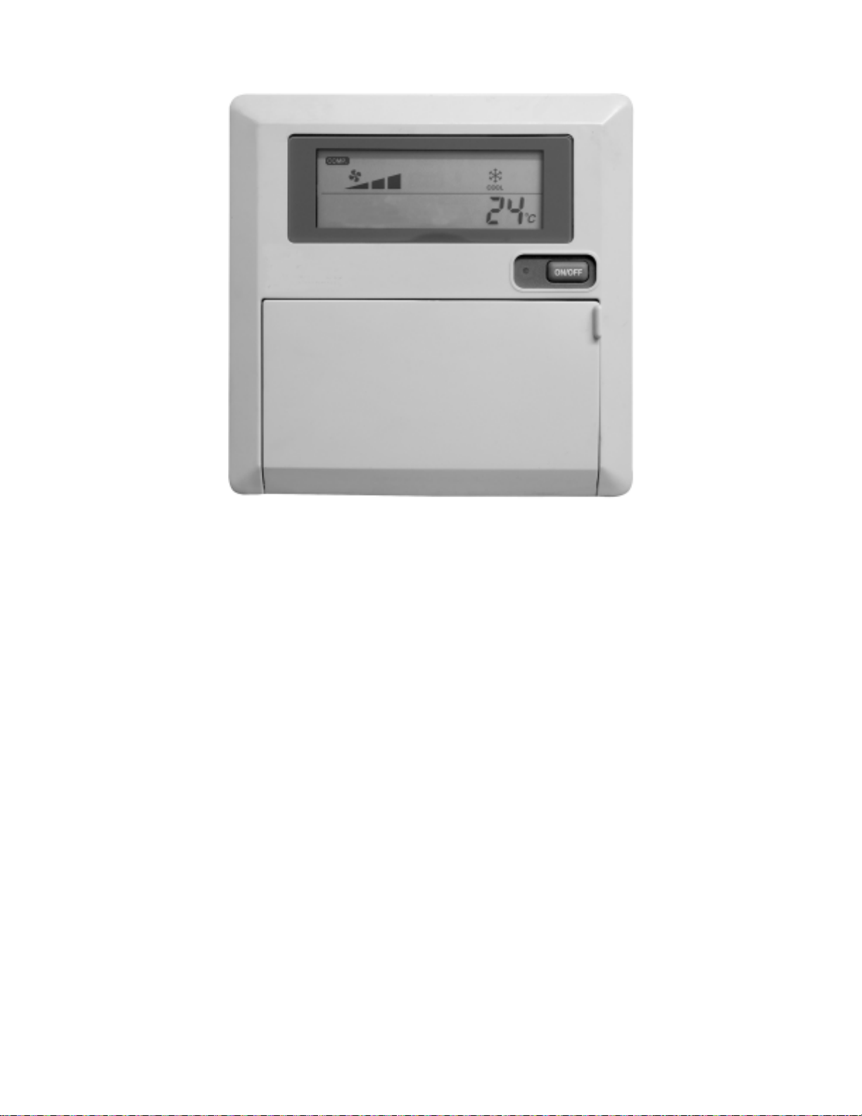
ELECTRONIC THERMOSTAT
LCD display: a) Room temperature display
b) Mode of operation (Cool/Heat/Auto/Fan system control)
c) Set temperature
d) Compressor Status - ON/OFF/FAULT
e) Error Codes
1. ON/OFF: Press the ON/OFF button & the unit shall be switched ON. A status Led adjacent to this button shall light up indicating the
unit is switched ON. To shut off the unit, press this button again.
2. MODE: Press the mode button to select the desired mode. On selection the corresponding icon shall be displayed on the LCD
display panel.
0
3. TEMPERA TURE RANGE AND SETTING: The operating temperature range is 16
the UP or DN button to select the desired temperature. The temperature setting is effective only for the Cool, Heat and Auto modes.
4. INDOOR (EVAPORAT OR) FAN: There is one indoor fan with single fan speed. When fan speed on LCD panel is HIGH, indoor fan
will always turns on. Indoor fan can be set off, when the compressor is cut off by setting the fan speed to AUTO on the LCD panel
by pressing Fan button. By pressing the Fan button again the fan speed can resume to HIGH.
C to 300C (610F to 860F), both inclusive. Press
5. COOL MODE: Whenever the unit is started in cool mode (without Pump Down Solenoid-PDS), the compressors will be turned on
one by one depending on the load requirement of the unit.
6. HEAT MODE (HEATER MODEL): Whenever the unit is started in heat mode, the heaters shall be switched ON one by one to
meet the load requirement.
15
Page 17
7. LEAD/LAG OPERATION: Whenever a compressor needs to be on, the controller will turn on the compressor with
the shorter accumulated run time provided its 3 minutes minimum off time has lapsed. Otherwise the other
compressor will on first. Similarly, the compressor with the longer accumulated run time will be the first one to be
cut off. This is to load the compressors evenly over long run period. Balance loading is enabled when compressor
#1 lead option is disabled.
8. AUTO MODE: In Auto mode, operating mode will be selected automatically between Heat and Cool mode, depend-
ing on the Room Temperature and Set Temperature.
9. ERROR CODE:
Error code is displayed on the LCD panel. When system on and error code is shown, the ON/OFF LED on the LCD panel will blink.
When system off, error code is still display for thermistor error but the ON/OFF LED will be off.
E06 Compressor 1 high pressure trip (or contact open)
E07 Compressor 2 high pressure trip (or contact open), (not applicable for single compressor units)
E10 Compressor 1 low pressure trip
E11 Compressor 2 low pressure trip, (not applicable for single compressor units)
CRANKCASE HEATER
The crankcase heater is provided to hold the compressor oil reservoir at higher temperature than the coldest part in the system.
• Power must be supplied to crankcase heater for a minimum of 12-hours prior to system start-up. If power is off for 6-hours or more,
crankcase heater must be energized for 12-hours before operating the system. Otherwise compressor damage may result.
PUMP DOWN CONTROL
If the unit is provided with pumpdown system, then a solenoid type valve is installed in the liquid line ahead of expansion valve to
prevent flow of refrigerant into the evaporator during off cycle. The controller is wired to solenoid valve which energize in cooling and
opening the valve. Whenever the thermostat temperature is satisfied, the solenoid will close followed compressor off after pumping the
refrigerant from low side of the system until the low pressure switch open the control circuit.
16
Page 18

MAINTENANCE INSTRUCTIONS
AIRFLOW ADJUSTMENT (Applicable for PT075 - PT360 only)
The airflow could be adjusted by adjusting pulleys of blower motor or belt tension with proper mounting and alignment of the pulleys:
• Refer to fan performance tables in the catalog for selecting applicable airflow, RPM and brake horse power at specified static
pressure.
• Select the appropriate drive as per motor and blower characteristic in the catalog.
• The set screw shall be loosened to make the pulley moving.
• Adjust pulley’s diameter, opening counter clockwise to reduce RPM and further reduce airflow, while closing clockwise increases
RPM and airflow.
• Tighten the set screw and then install the belts.
• Test the unit operating airflow for further adjustment.
CRANKCASE HEATER
• Periodic checking for proper operation or crankcase heater is highly recommended as follows:
a) Check continuity of the heater using multimeter device.
b) Check grounding of the heater by Meggar device (to prevent electrical hazards).
c) Observe whether the heater is warming down the compressor near the oil sump.
CLEANING OF COILS & FILTERS
• Turn off the power supply.
• Take out access panel of evaporator coil.
• Remove the filter from its access panel.
• Protect electrical components and motors from water washing.
• Clean the coil by flushing water by pressure washer followed by compressed air from supply to return direction.
• Filter shall be cleaned every six month, in some hygienic application it is recommended for replacement.
• Cleaning drain pan and trap is recommended once in a year to prevent bacteria growing under the coil.
BELT TENSION TESTING PROCEDURE INSTRUCTION (Applicable for PT075 - PT360 only)
To determine the lbs. force required to tension a drive, you simply do the following:
1. Measure the Belt span as shown.
2. Divide belt span by 64 to get belt deflection needed to check tension.
3. Set large "0" ring on span scale at required belt deflection. This scale is in 1/16" increments.
4. Set small "0" ring at zero on the "Force Scale" (plunger).
5. Place the larger end of the tension checker squarely on one belt at the center of the belt span. Apply force on the plunger until the
bottom of the large "0" ring is even with the top of the next belt or with the bottom of a straight edge laid across the sheaves.
6. Read the force scale under the small "0" ring to determine force required to give the needed deflection.
7. Compare the force scale reading with the correct value for the belt style and cross section used, as given in table on next page.
The force should be between the minimum and maximum values shown.
8. If there is too little deflection force, the belts should be tightened. If there is too much deflection force, the belts should be
loosened.
Note: Tension new drives at the maximum deflection force recommended. Check the tension at least two times during the first day's
operation as there normally will be a rapid decrease in belt tension until belts have run in. Check the tension periodically after the first
day's operation and keep tension in recommended area. The correct operating tension for a V-belt drive is the lowest tension at which
the belts will not slip under the peak load conditions. Shafts must be adequate for the tensions required.
17
Page 19
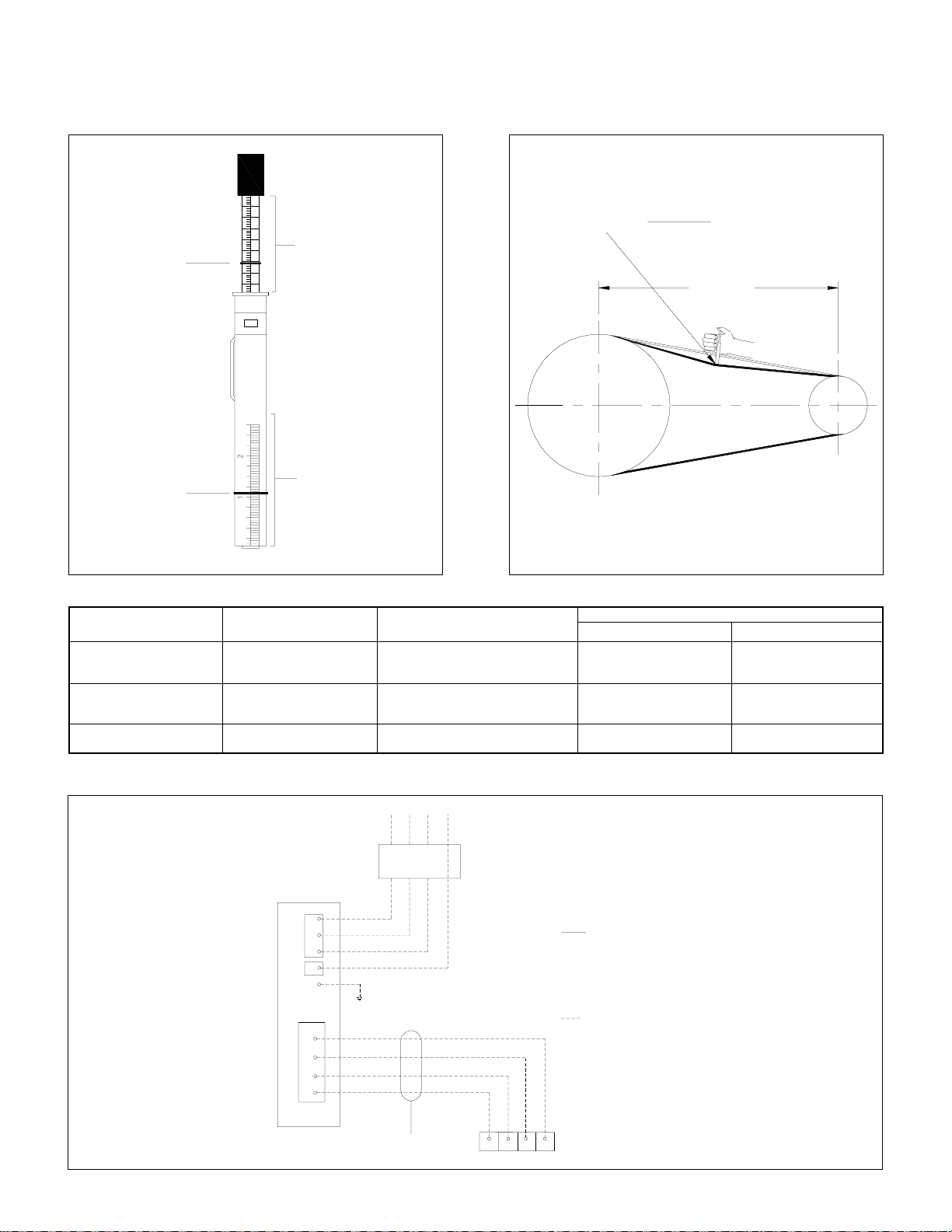
BELT TENSION TESTING PROCEDURE
BELT SPAN
64
SMALL
"0"
RING
DEFLECTION =
FORCE SCALE
BELT SPAN
LARGE
"0"
RING
SPAN SCALE
BELT TENSION CHECKER MEASURE THE BELT DEFLECTION FORCE
BELTS
BELT TYPE
–
A
B
BELT CROSS SECTION
3 L
4 L
5 L
SMALL PULLEY PITCH DIA. (P.D.)
RANGE
1.25 – 1.75
2 – 2.25
2.5 – 3
2.1 – 2.8
3 – 3.5
3.7 – 5
3 – 4.2
4.5 – 5.2
DEFLECTION FORCE - LBS.
MINIMUM
1/2
5/8
3/4
1-1/8
1-1/2
1-7/8
2
2-3/8
MAXIMUM
5/8
7/8
1-1/8
1-5/8
2-1/8
2-5/8
2-7/8
3-3/8
TYPICAL HIGH AND LOW VOLTAGE FIELD WIRING CONNECTIONS
N
FUSED DISCONNECT SWITCH
OR CIRCUIT BREAKER
A
INDOOR THERMOSTAT
18
B
LEGEND
ECB - ELECTRONIC CONTROL BOARD
HVTB - HIGH VOLTAGE TERMINAL BLOCK
LI - LINE1
L2 - LINE2
L3 - LINE3
N - NEUTRAL TERMINAL BLOCK
G - GROUND
FIELD WIRING
+5V GND
PACKAGED UNIT
CONTROL PANEL
L1
L2
HVTBNTB
L3
N
G
GND
+5V
ECB
B
A
L1 L3L2
CONTROL WIRES-INTERCONNECTING
( USE 16 TO 22 AWG WIRE)
Page 20
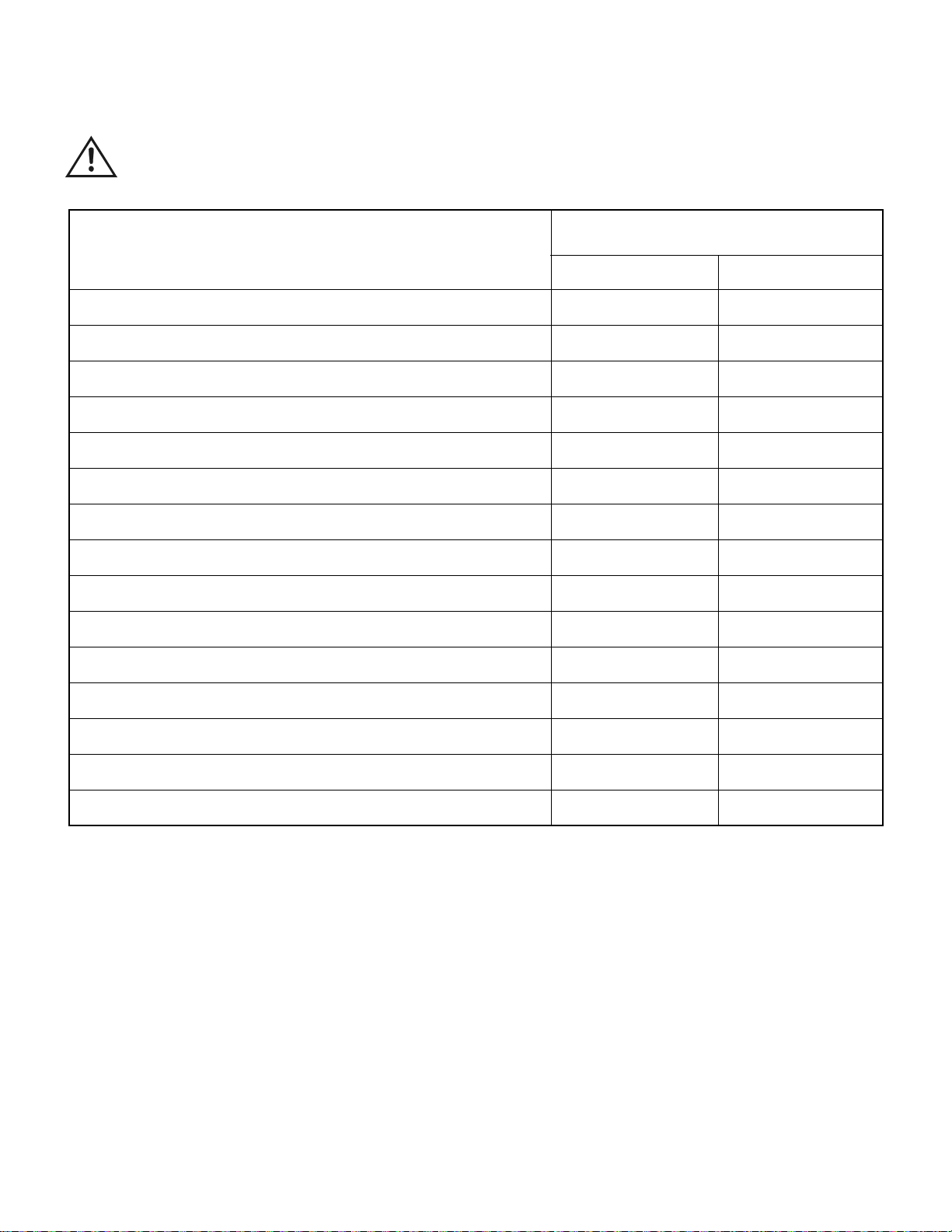
PREVENTIVE MAINTENANCE SCHEDULE
CAUTION: Disconnect power supply and allow all rotating parts to stop before servicing the unit.
FREQUENCY OF MAINTENANCE, MONTHS
I T E M
(FIRST 4 YEARS)
6
12
Clean air filter (Aluminum)*
Pressure wash condenser & cooling coil as required
Check blower belt, tension, wear tear/replace if required
Check alignment of pulleys
Clean drain pan, drain pipe
Clean blower wheel
Check for loose bolts/screws & tighten as necessary
Check all electrical controls, components, wiring terminals, etc..., for sparks,
over heat, loose connections/repair or correct
Check for rusted/paint
Check all temperature, pressure readings as applicable and satisfy the
operation performance
Run test all motors and check the amperage
Grease/oil as required
Check vibration isolators
X
X
X
X
X
X
X
X
X
X
X
X
X
Clean and fix thermal bulbs in the correct location. Insulate it.
Check canvass connections, insulation damage
* If fiberglass filters used, replace it yearly.
NOTE: Always observe for abnormal noise or vibration.
X
X
MAINTENANCE TOOLS/EQUIPMENT REQUIRED
STANDARD : Screw drivers (Slot & Phillips), adjustable wrenches, pliers, refrigeration wrenches & socket set wrenches, pulley
puller, etc.
SPECIAL : Manifold gauge set, R-22 charging cylinder, belt tension checker, leak detector, vacuum pump with electronic gauges,
thermometer, hook type ammeter/voltmeter/ohmmeter and oxy-acetylene brazing set etc.
19
Page 21

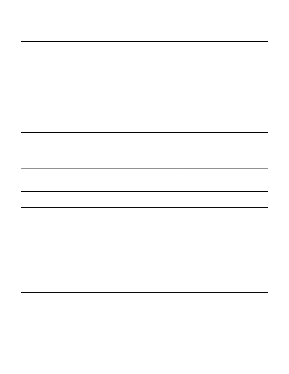
TROUBLE SHOOTING CHART
SYMPTOM CAUSES CHECK & CORRECTIVE MEASURE
Thermostat shows no display
Thermostat LCD panel display is not
bright & does not function properly
Blower not running, compressor short
cycles
Blower running, no sufficient air
Blower running, but with not enough
supply air
Blower running and delivers excess
air
Blower runs, compressor not working
Compressor runs, but short cycling
Thermostat shows faulty indication
Low suction pressure
High suction pressure
High discharge pressure
1. Power off/Blown fuse
2. Faulty field wiring
3. Loose connections
4. Defective thermostat
1. Battery life is over
1. Blower belt slipped/not fixed
2. Faulty wiring
3. Burned wiring
4. Defective blower motor contactor
5. Defective blower motor
1. Wrong rotation (Applicable initial start up/or after
a power failure), 3 phase motor
1. Loose Belt
2. Variable pulley wide open
3. Return air obstructed
4. High static pressure
5. Improper pulley selection
6. Closed dampers/improper air balance
7. Dirty filter
8. Dirty cooling coil
1. Variable pulley needs more tightening
2. Improper pulley/motor selection
3. Low external static pressure
1. Safety circuit open due to low suction pressure,
high discharge pressure, overload protector
2. Defective compressor contactor
3. Burned wiring
4. Defective compressor
1. Safety circuit open due to:
a) Low suction pressure
b) High discharge pressures
c) Overload protector
2. Thermostat in cold location
3. High thermostat setting
1. Safety circuit open due to:
a) Low pressure switch
b) High pressure switch
c) Overload protector
1. Less Freon
2. Loose belt
3. Variable pulley widely open
4. Dirty filter
5. Dirty cooling coil
6. Return air restricted
7. Improper expansion valve bulb installation/location
8.
Restriction in expansion valve/filter dryer
1. Excess freon charge
2. Excess air quantity
3. High room temperature condition
4. Undersize unit (serving large area)
5. Expansion valve widely open
6. Defective compressor valve
1. Condenser fan motor not working properly
2. Excess freon charge
3. Dirty condenser
4. High ambient condition/Air in condenser obstructed
5. Defective fan motor capacitor
6. Defective fan motor
20
1. Check the power. Switch ON the circuit breaker.
Replace fuse if it blown.
2. Check wiring against diagram.
3. Check and correct it.
4. Replace it.
1. Replace battery
1. Correct belt. Check tension and alignment.
2. Check wiring against diagram.
3. Check and correct it.
4. Replace if.
5. Replace it.
1. Check the rotation of blower, interchange phase
of blower motor from blower motor contactor.
1. Adjust it & check belt tension.
2. Adjust the pitch of the pulley.
3. Check and remove the obstructions.
4. Verify static pressure and fan performance data.
5. Change pulley (if blower motor ampere within rated load).
6. Check all dampers opened properly. Balance air.
7. Clean it.
8. Clean it.
1. Adjust the pitch of the pulley.
2. Select suitable combination.
3. Check the duct design.
1. Re-set the unit and determine the reason. Check
high & low pressure (refer to symptom for "low/
high suction pressure & high discharge pressure").
2. Replace it.
3. Check and replace it.
4. Replace it.
1. a) Verify the reason
(refer to symptom for "low suction pressure")
b) Verify the reason for high discharge pressure
(refer to symptom for "high discharge pressure").
c) Check dome temperature. RLA each phase.
Verify the reason.
2. Check and relocate as required.
3. Lower the temperature setting to 210C for test.
1. a) Verify the reason & correct it
for "low suction pressure")
b) Verify the reason for high discharge pressure.
(refer to symptom for "high discharge pressure").
c) Check comp. RLA against nameplate for each phase,
check comp. dome temperature, etc. & correct it.
1. Check for gas leak & charge freon as required.
2. Adjust it. Check belt tension.
3. Adjust the pulley.
4. Clean it.
5. Clean it.
6. Check return air grille sizes, etc. against design.
7. Verify and correct it.
8. Check and correct/replace it.
1. Verify and adjust it.
2. Adjust air quantity.
3. Check & verify. Isolate the area to be cooled & observe.
4. Check design/unit selection.
5. Check superheat & adjust it, if required.
6. Check and replace compressor.
1. Fan blade stuck with ventury. Check & correct it.
2. Check freon and adjust it, if necessary.
3. Clean it.
4. Verify the reason and correct it.
5. Check and replace it.
6. Check and replace it.
for low suction pressure
(refer to symptom
.
.
Page 22
TROUBLE SHOOTING CHART
SYMPTOM CAUSES CHECK & CORRECTIVE MEASURE
Unit works continuously, no sufficient
cooling
Unit not cooling properly during night
time
Not sufficiently cooling during
daytime
Cooling coil ices up
Unit is not restarting (after a cut-off)
Unit is taking long time to restart
Compressor goes lockout (pump
down system)
Taking more time for the pumpdown
cycle, cooling coil ices up
Noisy unit
Unit operational noise listening inside
the building
Compressor not working
Circuit breaker of the unit trips
1. Low suction pressure
2. High discharge pressure
3. Less air quantity
4. Cooling coil ices up
5. Second stage (If exists) not working
6. Serving large area
1. Low ambient condition
2. Safety low pressure switch open due to low
suction pressure
3. Fan cycling (whenever applicable) setting low
4. Thermostat setting too low
5. Cooling coil ices-up
6. Less air quantity
1. High discharge pressure
2. High thermostat setting
3. Serving large area
4. Less air quantity
5. High ambient condition
6. Dirty condenser
1. Less freon
2. Less air quantity
3. Dirty filter
4. Dirty cooling coil
1. Safety circuit open due to low pressure switch
1. Thermostat in cold location
1. Imbalance freon
2. Malfunctioning pumpdown solenoid valve
1. Leaky pumpdown solenoid valve
1. Improper installation
2. Improper vibration isolators
3. Loose parts or mountings
4. Tubing rattle
5. Bent fan blade causes vibration
6. Defective bearings
7. Belt tension is high
8. Blower motor pulley is not aligned
1. Improper installation
2. Improper vibration isolators
3. Abnormal noise in the unit
4. Unit too close to the slab/wall openings
5. Duct design (high static)
6. Wooden packing beneath the compressor is not removed
1. Low voltage
2. Single phase failure
3. Burned wirings
4. Overload protector open
5. Defective contactor
6. Burned compressor motor winding
7. Damaged (stuck) compressor
1. Burned wirings
2. Grounded wirings
3. Faulty field wiring
4. Grounded compressor/blower motor
5. Undersize circuit breaker
1. Verify the reason & correct it
for "low suction pressure")
2. Verify the reason and adjust the freon, if required.(refer
to symptom for "high discharge pressure").
3. Refer to symptom for "blower works, less air".
4. Determine the reason
"cooling coil ice up")
5. Set the thermostat to lower temperature (21
or verify the reason.
6. Check the design.
1. Check and verify the ambient temperature.
2. Check the reason and correct it
symptom for "low suction pressure")
3. Adjust the fan cycling.
4. Adjust the thermostat setting.
5.Verify the reason and correct it
symptom for "cooling coil ice up").
6.Verify the reason and correct it
symptom for "blower works, less air")
1. Check and verify the reason (refer to symptom
for "high discharge pressure").
2. Adjust thermostat.
3. Check the design/unit selection.
4. Check and verify the reason
for "blower works, less air")
5. Check the ambient condition.
6. Clean it.
1. Check for gas leak & charge freon as required.
2. Determine the reason and correct it
symptom for "blower works, less air")
3. Clean it.
4. Clean it.
1. Rectify the reason of low suction pressure
to symptom for "low suction pressure")
1. Shift the location as required.
1. Check freon charge and confirm FLA.
2. Check pumpdown solenoid valve operation.
1. Check pumpdown solenoid valve and replace it.
1.Check and correct it properly.
2. Check and correct it properly.
3. Check and tighten.
4. Tighten the pipe support.
5. Check the balance, alignment, bracket, etc.
Correct it/replace it.
6. Replace the motor.
7. Adjust belt tension.
8. Align pulley.
1. Check and correct it.
2. Check and correct it.
3. Verify the reason of noisy unit & correct it.
4. Verify the design/Relocate the unit if necessary.
5. Check & verify the design.
6. Remove wooden packing (if any).
1. Rectify the reason & correct it.
2. Check the compressor amperage each phase.
3. Check and correct it.
4. Check and verify the reason.
5. Check and replace it.
6. Check and replace it.
7. Check and replace it.
1. Check and correct the wiring.
2. Check meggar test.
3. Check wiring against diagram.
4. Replace it, if required.
5. Check the circuit breaker ratings.
(refer to symptom
.
(refer to symptom for
& correct it.
(refer to
.
(refer to
(refer to
.
(refer to symptom
.
(refer to
.
0
(refer
.
C)/
21
Page 23
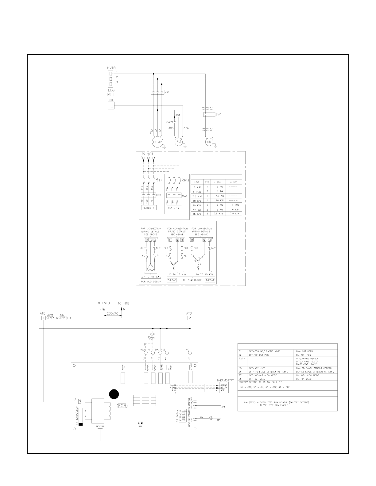
TYPICAL SCHEMATIC WIRING DIAGRAM
MODELS : PT036 - PT075 (Single compressor units)
HEATER DATA TABLE
(SEE HEATER DATA TABLE)
HEATER CONNECTION DETAILS
DIP SWITCH SETTINGS
JUMPER SETTING ON ECB
NOTE: 1. Refer to next page for legend, notes & wiring diagram for optional items.
2. Refer to unit control box (inside panel) for exact wiring diagram.
22
Page 24
*
FACTORY INSTALLED B.M SPEED
*
TO HVTB
TO HVTB
TO NTB
TO NTB
*
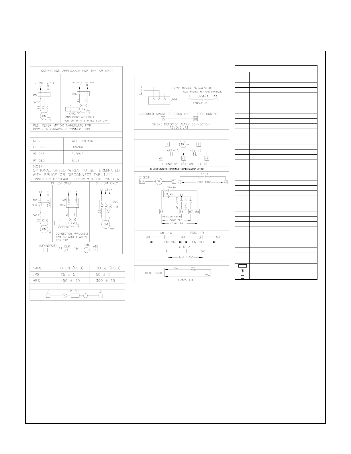
PRESSURE SWITCH SETTINGS
CRANKCASE HEATER CONNECTION
TYPICAL SCHEMATIC WIRING DIAGRAM
MODELS : PT036 - PT075 (Single compressor units)
STANDARD OPTIONS
1. UVM OPTION
*
2. SMOKE DETECTOR OPTION
3. VOLT FREE CONTACT OPTIONS
A. UNIT ON & OFF INDICATION OPTION
*
C. BM ON,OFF & TRIP INDICATION OPTION
4. HPS CONNECTION OPTION
AR AUXILIARY RELAY
AFS AIRFLOW SWITCH
ATB AUXILIARY TERMINAL BLOCK
BM BLOWER MOTOR
BMC BLOWER MOTOR CONTACTOR
CC COMPRESSOR CONTACTOR
CCA AUXILIARY CONTACT
CB CIRCUIT BREAKER
C. HTR CRANKCASE HEATER
COMP COMPRESSOR
ECB ELECTRONIC CONTROL BOARD
FCS FAN CYCLING SWITCH
F FUSE
FL FUSE LINK
FM FAN MOTOR (CONDENSER)
FMC FAN MOTOR CONTACTOR
FR FAULT RELAY
HC HEATER CONTACTOR
HPS HIGH PRESSURE SWITCH
HVTB HIGH VOLTAGE TERMINAL BLOCK
HTR HEATER
JP JUMPER
L1 LINE 1
L2 LINE 2
L3 LINE 3
LPS LOW PRESSURE SWITCH
LUG LUG GROUND
NTB NEUTRAL TERMINAL BLOCK
O/L OVER LOAD
OHT OVER HEAT THERMOSTAT
PDS PUMP DOWN SOLENOID
SSPS SOLID STATE PROTECTIVE SYSTEM
SD SMOKE DETECTOR
TRANS TRANSFORMER
T'STAT THERMOSTAT
UVM UNDER VOLTAGE MONITOR
_ _ _
+
1. POWER SUPPLY, 380/415V-3PH-50Hz.
2. ANY WIRE REPLACEMENT SHOULD BE OF 900C OR ITS
EQUIVALENT. USE COPPER CONDUCTOR WIRES ONLY.
3. IF PDS & HEATERS ARE FACTORY INSTALLED, PLEASE
READ BROKEN LINES AS CONTINUOUS LINES.
4. POWER MUST BE SUPPLIED TO CRANKCASE HEATER FOR
MINIMUM OF 12 HOURS PRIOR TO SYSTEM START UP.
IF POWER IS OFF 6 HOURS OR MORE, CRANKCASE
HEATER MUST BE ON FOR 12 HOURS BEFORE OPERATING THE SYSTEM.
FAILURE TO FOLLOW THESE INSTRUCTIONS MAY RESULT IN COMPRESSOR DAMAGE.
5. FUSED DISCONNECT SWITCH OR CIRCUIT BREAKER
TO BE PROVIDED BY CONSUMER WITH RATING AS
RECOMMENDED BY COOLINE.
6. COMPRESSOR IS PROVIDED WITH INTERNAL OVERLOAD.
7. IF ANY CHANGE IN DIP SWITCH SETTING IS REQUIRED,
TURN OFF POWER FIRST & SET REQUIRED SETTING.
LEGEND
FIELD WIRING
DISCONNECT TAB - 1/4"
SPLICE-CLOSED END
TERMINAL BLOCK OR TERMINATION POINT
NOTES
23
Page 25
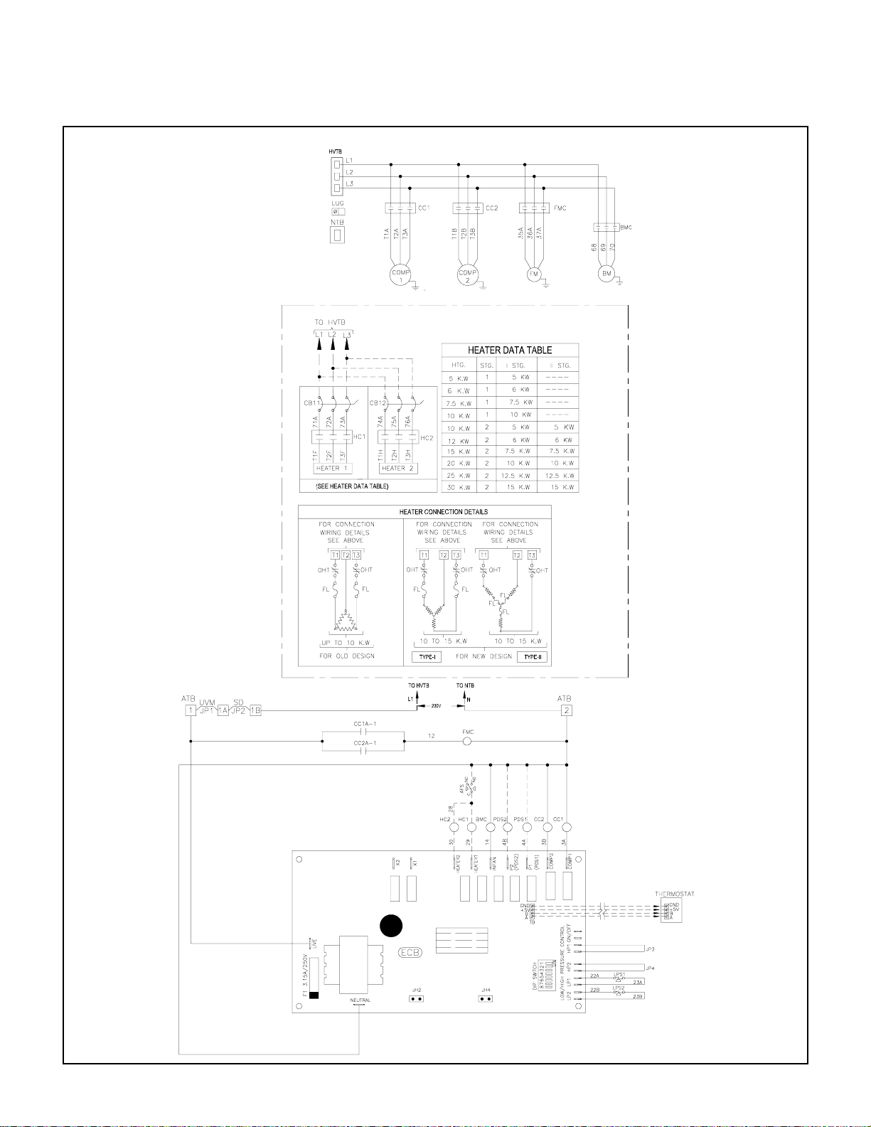
TYPICAL SCHEMATIC WIRING DIAGRAM
MODELS : PT090 - PT120 (Dual compressor units)
NOTE: 1. Refer to next page for legend, notes & wiring diagram for optional items.
2. Refer to unit control box (inside panel) for exact wiring diagram.
24
Page 26
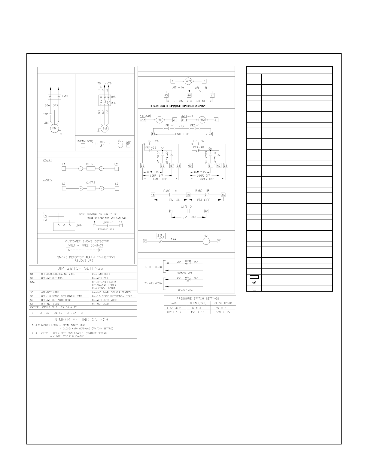
CONNECTION APPLICABLE FOR
1PH FM ONLY
TO HVTB
TO NTB
N
L2
CRANKCASE HEATER CONNECTION
STANDARD OPTIONS
1. UVM OPTION
2. SMOKE DETECTOR OPTION
TYPICAL SCHEMATIC WIRING DIAGRAM
MODELS : PT090 - PT120 (Dual compressor units)
3. VOLT FREE CONTACT OPTIONS
BM WITH EXTERNAL OLR
A. UNIT ON & OFF INDICATION OPTION
C. BM ON,OFF & TRIP INDICATION OPTION
FAN MOTOR CONTROL CONNECTION
(APPLICABLE FOR FM WITH T.O.P)
HPS OPTION
AR AUXILIARY RELAY
AFS AIRFLOW SWITCH
ATB AUXILIARY TERMINAL BLOCK
BM BLOWER MOTOR
BMC BLOWER MOTOR CONTACTOR
CC COMPRESSOR CONTACTOR
CCA AUXILIARY CONTACT
CB CIRCUIT BREAKER
C. HTR CRANKCASE HEATER
COMP COMPRESSOR
ECB ELECTRONIC CONTROL BOARD
FCS FAN CYCLING SWITCH
F FUSE
FL FUSE LINK
FM FAN MOTOR (CONDENSER)
FMC FAN MOTOR CONTACTOR
FR FAULT RELAY
HC HEATER CONTACTOR
HPS HIGH PRESSURE SWITCH
HVTB HIGH VOLTAGE TERMINAL BLOCK
HTR HEATER
JP JUMPER
L1 LINE 1
L2 LINE 2
L3 LINE 3
LPS LOW PRESSURE SWITCH
LUG LUG GROUND
NTB NEUTRAL TERMINAL BLOCK
O/L OVER LOAD
OHT OVER HEAT THERMOSTAT
PDS PUMP DOWN SOLENOID
SSPS SOLID STATE PROTECTIVE SYSTEM
SD SMOKE DETECTOR
TRANS TRANSFORMER
T'STAT THERMOSTAT
UVM UNDER VOLTAGE MONITOR
_ _ _
FIELD WIRING
+
DISCONNECT TAB - 1/4"
SPLICE-CLOSED END
TERMINAL BLOCK OR TERMINATION POINT
1. POWER SUPPLY, 380/415V-3PH-50Hz.
2. ANY WIRE REPLACEMENT SHOULD BE OF 900C OR ITS
EQUIVALENT. USE COPPER CONDUCTOR WIRES ONLY.
3. IF PDS & HEATERS ARE FACTORY INSTALLED, PLEASE
READ BROKEN LINES AS CONTINUOUS LINES.
4. POWER MUST BE SUPPLIED TO CRANKCASE HEATER FOR
MINIMUM OF 12 HOURS PRIOR TO SYSTEM START UP.
IF POWER IS OFF 6 HOURS OR MORE, CRANKCASE
HEATER MUST BE ON FOR 12 HOURS BEFORE OPERATING THE SYSTEM.
FAILURE TO FOLLOW THESE INSTRUCTIONS MAY RESULT IN COMPRESSOR DAMAGE.
5. FUSED DISCONNECT SWITCH OR CIRCUIT BREAKER
TO BE PROVIDED BY CONSUMER WITH RATING AS
RECOMMENDED BY COOLINE.
6. COMPRESSORS ARE PROVIDED WITH INTERNAL OVERLOAD.
7. IF ANY CHANGE IN DIP SWITCH SETTING IS REQUIRED,
TURN OFF POWER FIRST & SET REQUIRED SETTING.
LEGEND
NOTES
25
Page 27
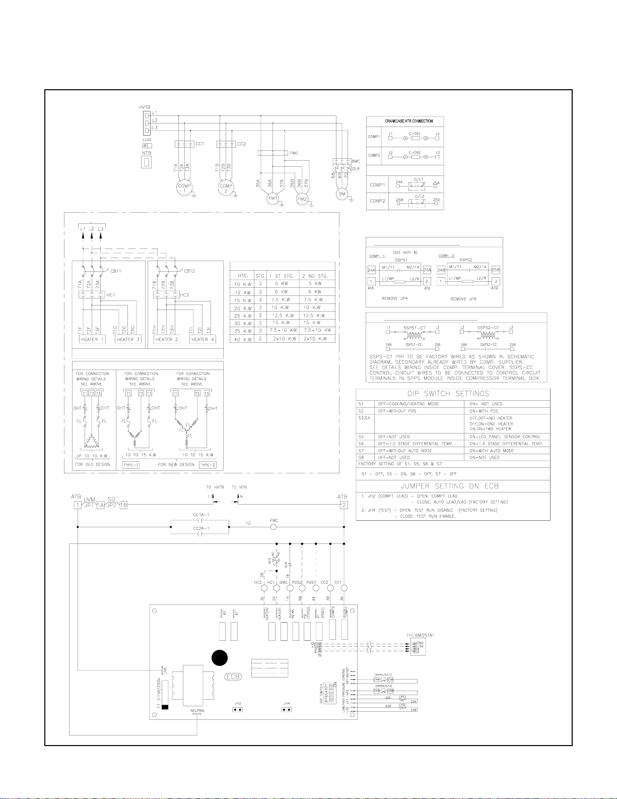
TO HVTB
(SEE HEATER DATA TABLE)
HEATER CONNECTION DETAILS
TYPICAL SCHEMATIC WIRING DIAGRAM
MODELS : PT180 - PT240 (Dual compressor units)
CONNECTION FOR COMPRESSOR
WITH MOTOR OVERLOAD
CONNECTION FOR SCROLL COMP. WITH SSPS
HEATER DATA TABLE
CONNECTION FOR MANUEROP COMP. WITH SSPS
230V
NOTE: 1. Refer to next page for legend, notes & wiring diagram for optional items.
2. Refer to unit control box (inside panel) for exact wiring diagram.
26
Page 28
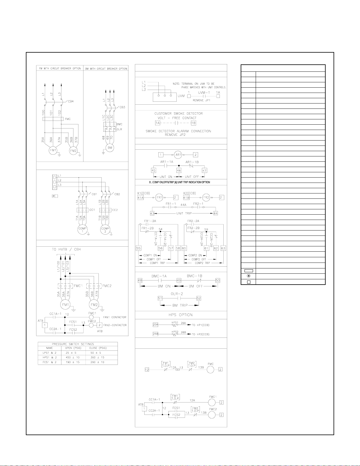
TYPICAL SCHEMATIC WIRING DIAGRAM
TO HVTB
COMP. WITH CIRCUIT BREAKER OPTION
HVTB
LUG
LOW AMBIENT OPTION
MODELS : PT180 - PT240 (Dual compressor units)
STANDARD OPTIONS
TO HVTB
1. UVM OPTION
2. SMOKE D ETECTOR OPTION
3. VOLT FREE CONTACT OPTIONS
A. UNIT ON & OFF INDICATION OPTION
C. BM ON,OFF & TRIP INDICATION OPTION
FAN MOTOR CONTROL CONNECTION
(APPLICABLE FOR FM WITH T.O.P)
A) STANDARD CONNECTION
B) WITH LOW AMBIENT OPTION
AR AUXILIARY RELAY
AFS AIRFLOW SWITCH
ATB AUXILIARY TERMINAL BLOCK
BM BLOWER MOTOR
BMC BLOWER MOTOR CONTACTOR
CC COMPRESSOR CONTACTOR
CCA AUXILIARY CONTACT
CB CIRCUIT BREAKER
C. HTR CRANKCASE HEATER
COMP COMPRESSOR
ECB ELECTRONIC CONTROL BOARD
FCS FAN CYCLING SWITCH
F FUSE
FL FUSE LINK
FM FAN MOTOR (CONDENSER)
FMC FAN MOTOR CONTACTOR
FR FAULT RELAY
HC HEATER CONTACTOR
HPS HIGH PRESSURE SWITCH
HVTB HIGH VOLTAGE TERMINAL BLOCK
HTR HEATER
JP JUMPER
L1 LINE 1
L2 LINE 2
L3 LINE 3
LPS LOW PRESSURE SWITCH
LUG LUG GROUND
NTB NEUTRAL TERMINAL BLOCK
O/L OVER LOAD
OHT OVER HEAT THERMOSTAT
PDS PUMP DOWN SOLENOID
SSPS SOLID STATE PROTECTIVE SYSTEM
SD SMOKE DETECTOR
TRANS TRANSFORMER
T'STAT THERMOSTAT
UVM UNDER VOLTAGE MONITOR
_ _ _
FIELD WIRING
+
DISCONNECT TAB - 1/4"
SPLICE-CLOSED END
TERMINAL BLOCK OR TERMINATION POINT
1. POWER SUPPLY, 380/415V-3PH-50Hz.
2. ANY WIRE REPLACEMENT SHOULD BE OF 900C OR ITS
EQUIVALENT. USE COPPER CONDUCTOR WIRES ONLY.
3. IF PDS & HEATERS ARE FACTORY INSTALLED, PLEASE
READ BROKEN LINES AS CONTINUOUS LINES.
4. POWER MUST BE SUPPLIED TO CRANKCASE HEATER FOR
MINIMUM OF 12 HOURS PRIOR TO SYSTEM START UP.
IF POWER IS OFF 6 HOURS OR MORE, CRANKCASE
HEATER MUST BE ON FOR 12 HOURS BEFORE OPERATING THE SYSTEM.
FAILURE TO FOLLOW THESE INSTRUCTIONS MAY RESULT IN COMPRESSOR DAMAGE.
5. FUSED DISCONNECT SWITCH OR CIRCUIT BREAKER
TO BE PROVIDED BY CONSUMER WITH RATING AS
RECOMMENDED BY COOLINE.
6. COMPRESSORS ARE PROVIDED WITH INTERNAL OVERLOAD.
7. IF COMPRESSOR IS SUPPLIED WITH SSPS, CONNECT AS
SHOWN. PLEASE ALLOW 2-3 MINUTES FOR SSPS SWITCH
TO CLOSE, BEFORE STARTING THE UNIT.
8. IF ANY CHANGE IN DIP SWITCH SETTING IS REQUIRED,
TURN OFF POWER FIRST & SET REQUIRED SETTING.
LEGEND
NOTES
27
Page 29
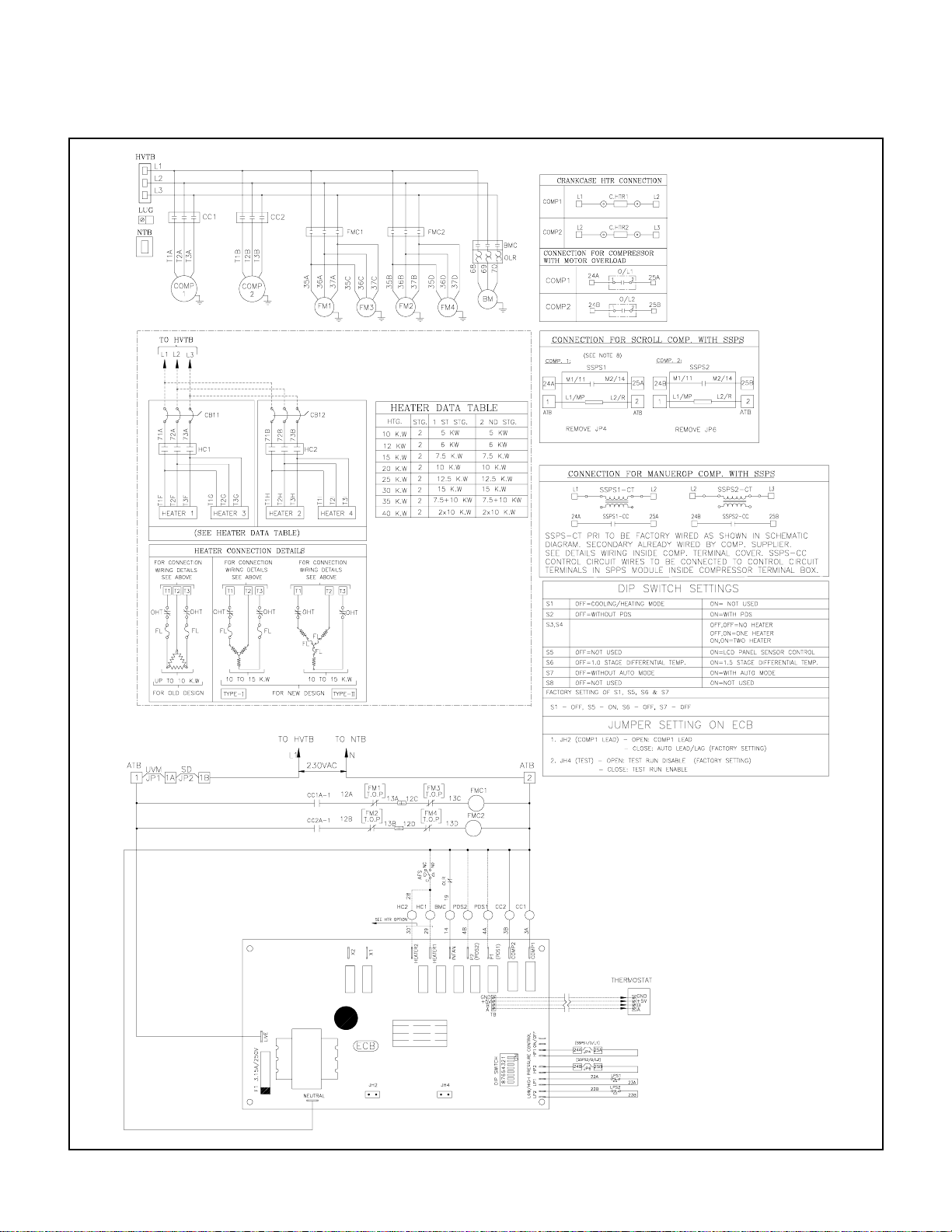
TYPICAL SCHEMATIC WIRING DIAGRAM
MODELS : PT300 - PT360 (Dual compressor units)
NOTE: 1. Refer to next page for legend, notes & wiring diagram for optional items.
2. Refer to unit control box (inside panel) for exact wiring diagram.
28
Page 30
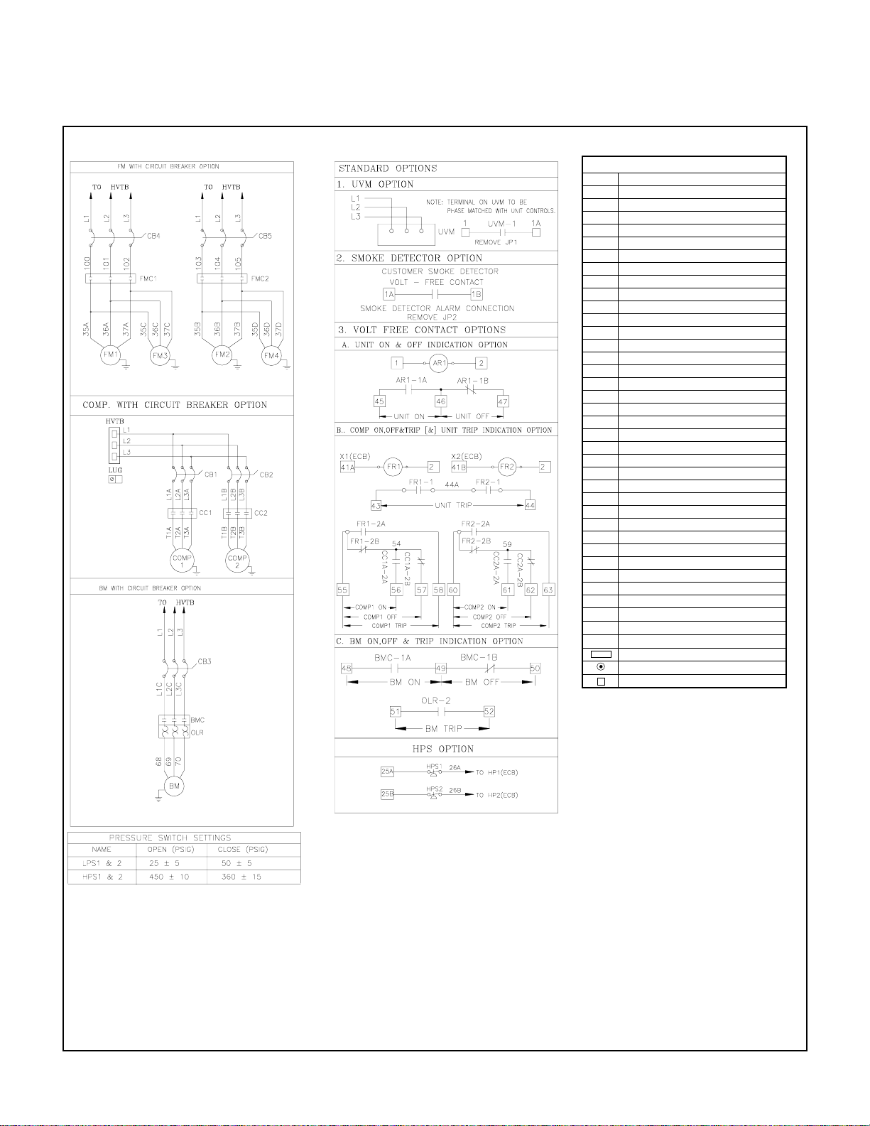
TYPICAL SCHEMATIC WIRING DIAGRAM
MODELS : PT300 - PT360 (Dual compressor units)
AR AUXILIARY RELAY
AFS AIRFLOW SWITCH
ATB AUXILIARY TERMINAL BLOCK
BM BLOWER MOTOR
BMC BLOWER MOTOR CONTACTOR
CC COMPRESSOR CONTACTOR
CCA AUXILIARY CONTACT
CB CIRCUIT BREAKER
C. HTR CRANKCASE HEATER
COMP COMPRESSOR
ECB ELECTRONIC CONTROL BOARD
FCS FAN CYCLING SWITCH
F FUSE
FL FUSE LINK
FM FAN MOTOR (CONDENSER)
FMC FAN MOTOR CONTACTOR
FR FAULT RELAY
HC HEATER CONTACTOR
HPS HIGH PRESSURE SWITCH
HVTB HIGH VOLTAGE TERMINAL BLOCK
HTR HEATER
JP JUMPER
L1 LINE 1
L2 LINE 2
L3 LINE 3
LPS LOW PRESSURE SWITCH
LUG LUG GROUND
NTB NEUTRAL TERMINAL BLOCK
O/L OVER LOAD
OHT OVER HEAT THERMOSTAT
PDS PUMP DOWN SOLENOID
SSPS SOLID STATE PROTECTIVE SYSTEM
SD SMOKE DETECTOR
TRANS TRANSFORMER
T'STAT THERMOSTAT
UVM UNDER VOLTAGE MONITOR
_ _ _
FIELD WIRING
+
DISCONNECT TAB - 1/4"
SPLICE-CLOSED END
TERMINAL BLOCK OR TERMINATION POINT
1. POWER SUPPLY, 380/415V-3PH-50Hz.
2. ANY WIRE REPLACEMENT SHOULD BE OF 900C OR ITS
EQUIVALENT. USE COPPER CONDUCTOR WIRES ONLY.
3. IF PDS & HEATERS ARE FACTORY INSTALLED, PLEASE
READ BROKEN LINES AS CONTINUOUS LINES.
4. POWER MUST BE SUPPLIED TO CRANKCASE HEATER FOR
MINIMUM OF 12 HOURS PRIOR TO SYSTEM START UP.
IF POWER IS OFF 6 HOURS OR MORE, CRANKCASE
HEATER MUST BE ON FOR 12 HOURS BEFORE OPERATING THE SYSTEM.
FAILURE TO FOLLOW THESE INSTRUCTIONS MAY RESULT IN COMPRESSOR DAMAGE.
5. FUSED DISCONNECT SWITCH OR CIRCUIT BREAKER
TO BE PROVIDED BY CONSUMER WITH RATING AS
RECOMMENDED BY COOLINE.
6. COMPRESSORS ARE PROVIDED WITH INTERNAL OVERLOAD.
7. IF COMPRESSOR IS SUPPLIED WITH SSPS, CONNECT AS
SHOWN. PLEASE ALLOW 2-3 MINUTES FOR SSPS SWITCH
TO CLOSE, BEFORE STARTING THE UNIT.
8. IF ANY CHANGE IN DIP SWITCH SETTING IS REQUIRED,
TURN OFF POWER FIRST & SET REQUIRED SETTING.
LEGEND
NOTES
29
Page 31
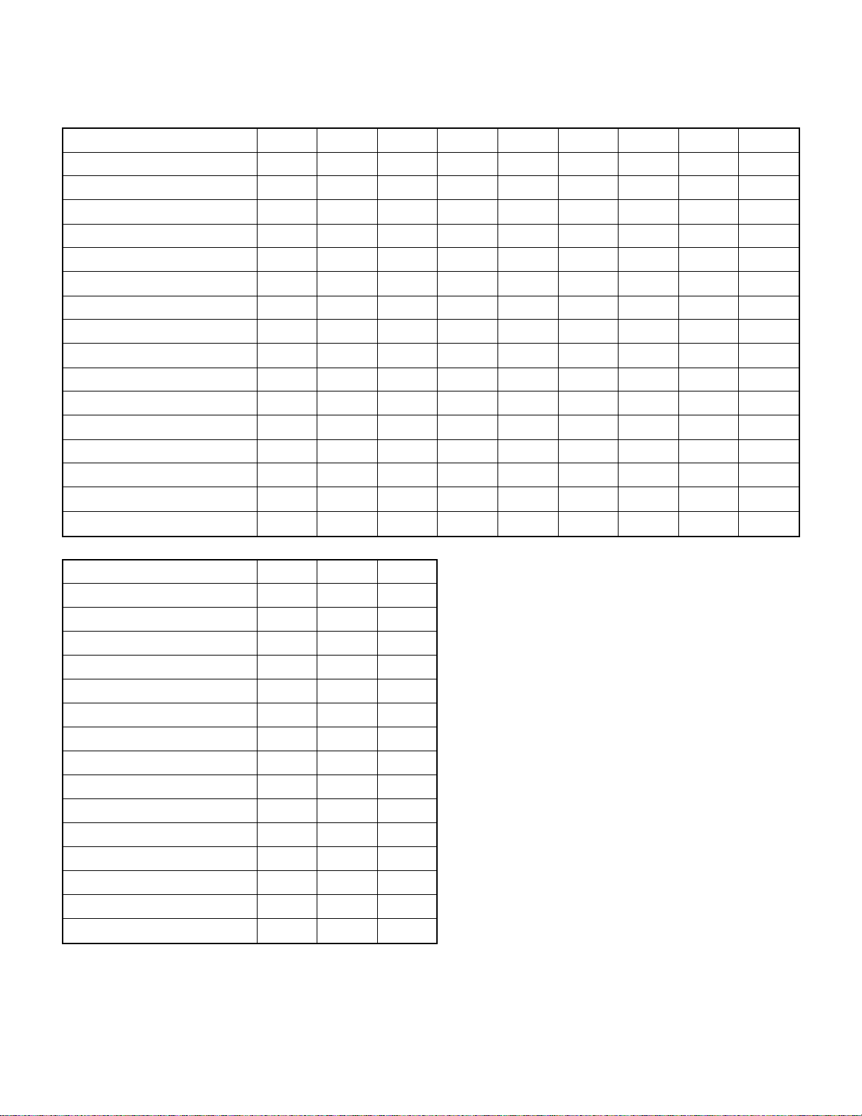
PARTS LIST
MODEL NUMBER PT036L PT048L PT060L PT075L PT090 PT100L PT120L PT180L PT215L
COMPRESSOR
FAN MOTOR
FAN MOTOR CAPACITOR
BlOWER MOTOR (STANDARD)
BLOWER WHEEL
CONDENSER FAN PROPELLER
COMPRESSOR CONTACTOR
BL0WER MOTOR CONTACTOR
AIRFLOW SWITCH
EXPANSION VALVE
DISTRIBUTOR
LOW PRESSURE SWITCH
HIGH PRESSURE SWITCH (OPTION)800-558-00 800-558-00 800-558-00 800-558-00 800-558-00 800-558-00 800-558-00 800-558-00 800-558-00
FAN GRILLE
FILTER DRIER
SIGHT GLASS (OPTION)
800-684-08 800-672-52 800-643-01 800-674-78 800-684-09 800-672-52 800-674-25
800-555-26 800-555-26 800-555-26 800-555-26 800-545-68 800-545-68 800-545-68 800-545-68 800-545-68
800-353-15 800-353-15 800-353-15 800-353-15 N.A. N.A. N.A. N.A. N.A.
800-546-94 800-546-94 800-546-95 800-544-13 800-544-16 800-544-16 800-544-17 800-544-72 800-544-72
800-707-10 800-707-10 800-707-10 800-707-46 800-707-02 800-707-02 800-707-02 800-707-02 800-707-23
800-225-02 800-225-02 800-225-02 800-225-02 800-224-23 800-224-23 800-224-23 800-224-23 800-224-23
800-095-01 800-095-01 800-095-01 800-095-01 800-095-01 800-095-01 800-095-01 800-095-01 800-736-22
800-736-27 800-736-27 800-736-27 800-095-01 800-095-01 800-095-01 800-095-01 800-098-55 800-098-55
800-005-02 800-005-02 800-005-02 800-005-02 800-005-02 800-005-02 800-005-02 800-005-02 800-005-02
800-195-16 800-195-20 800-195-22 800-181-00 800-183-01 800-181-00 800-181-00 800-182-00 800-182-00
800-194-13 800-194-13 800-194-17 800-191-01 800-191-00 800-191-00 800-191-00 800-196-00 800-194-01
800-557-00 800-557-00 800-557-00 800-557-00 800-557-00 800-557-00 800-557-00 800-557-00 800-557-00
800-625-46 800-625-46 800-625-46 800-625-46 800-625-29 800-625-29 800-625-29 800-625-74 800-625-74
800-531-08 800-531-08 800-531-08 800-531-08 800-531-08 800-531-08 800-531-08 800-531-05 800-531-05
800-201-00 800-201-00 800-201-00 800-201-00 800-201-00 800-201-00 800-200-00 800-200-00 800-200-00
800-674-67/81
800-674-38
MODEL NUMBER PT240L PT300L PT360L
COMPRESSOR
800-674-19 800-674-12 800-674-72
FAN MOTOR
BlOWER MOTOR (STANDARD)
BLOWER WHEEL
CONDENSER FAN PROPELLER
COMPRESSOR CONTACTOR
BL0WER MOTOR CONTACTOR
AIRFLOW SWITCH
EXPANSION VALVE
DISTRIBUTOR
LOW PRESSURE SWITCH
HIGH PRESSURE SWITCH (OPTION)800-558-00 800-558-00 800-558-00
FAN GRILLE
FILTER DRIER
SIGHT GLASS (OPTION)
800-545-68 800-545-68 800-545-68
800-544-73 800-544-73 800-544-74
800-707-23 800-707-23 800-707-23
800-224-23 800-225-02 800-225-02
800-736-22 800-736-22 800-736-22
800-098-55 800-098-55 800-098-57
800-005-02 800-005-02 800-005-02
800-185-00 800-186-00 800-186-00
800-194-01 800-196-10 800-191-34
800-557-00 800-557-00 800-557-00
800-625-74 800-625-46 800-625-46
800-531-05 800-531-05 800-531-01
800-200-00 800-200-00 800-200-01
OPTIONAL ITEMS:
ANTI ICE THERMOSTAT : 800-644-22 (COMMON TO ALL MODELS)
RETURN AIR FILTERS
Aluminum filter (1” Thick) : 800-254-10 (2 Each) for PT036 - PT060, 800-254-11 (2 Each) for PT075, 800-254-12 (2 Each) for PT090 - PT120,
Aluminum filter (2” Thick) : 800-254-16 (2 Each) for PT036 - PT060, 800-254-17 (2 Each) for PT075, 800-254-18 (2 Each) for PT090 - PT120,
800-254-13 (2 Each) for PT180, 800-254-14 (4 Each) for PT215 - PT240 & 800-254-15 (4 Each) for PT300 - PT360.
800-254-19 (2 Each) for PT180, 800-254-20 (4 Each) for PT215 - PT240 & 800-254-21 (4 Each) for PT300 - PT360.
30
 Loading...