

Page 1
Page 2

Page 3

INDEX
Contents Page
Model decoding ........................................................................................................................................ 4
Unit features, standard specifications & options.................................................................................... 5-8
Physical data ....................................................................................................................................... 9-12
Selection procedure .......................................................................................................................... 13-14
Performance data .............................................................................................................................. 15-20
Electrical data ......................................................................................................................................... 21
Water side pressure drop ....................................................................................................................... 22
Unit dimensions ................................................................................................................................ 23-28
Typical schematic wiring diagram...................................................................................................... 29-30
Microprocessor controller ....................................................................................................................... 31
Troubleshooting guide ....................................................................................................................... 32-33
Application guidelines ........................................................................................................................ 34-43
Rigging instructions ................................................................................................................................ 44
Installation clearance .............................................................................................................................. 45
Mounting location ................................................................................................................................... 46
Load distribution ................................................................................................................................ 47-48
CONTINUING RESEARCH RESULTS IN STEADY IMPROVEMENTS.
THEREFORE, THESE SPECIFICATIONS ARE SUBJECT TO CHANGE WITHOUT NOTICE.
3
Page 4
13 & 14
OPTIONS
&
ACCESSORIES
SEE NOTE # 2
BELOW
12
HGBP
OPTIONS
WITHOUT HGBP
B : HGBP (OPTIONAL)
A : STANDARD UNIT
11
COOLER
OPTIONS
10
OPTIONS
CIRCUIT BREAKER
9
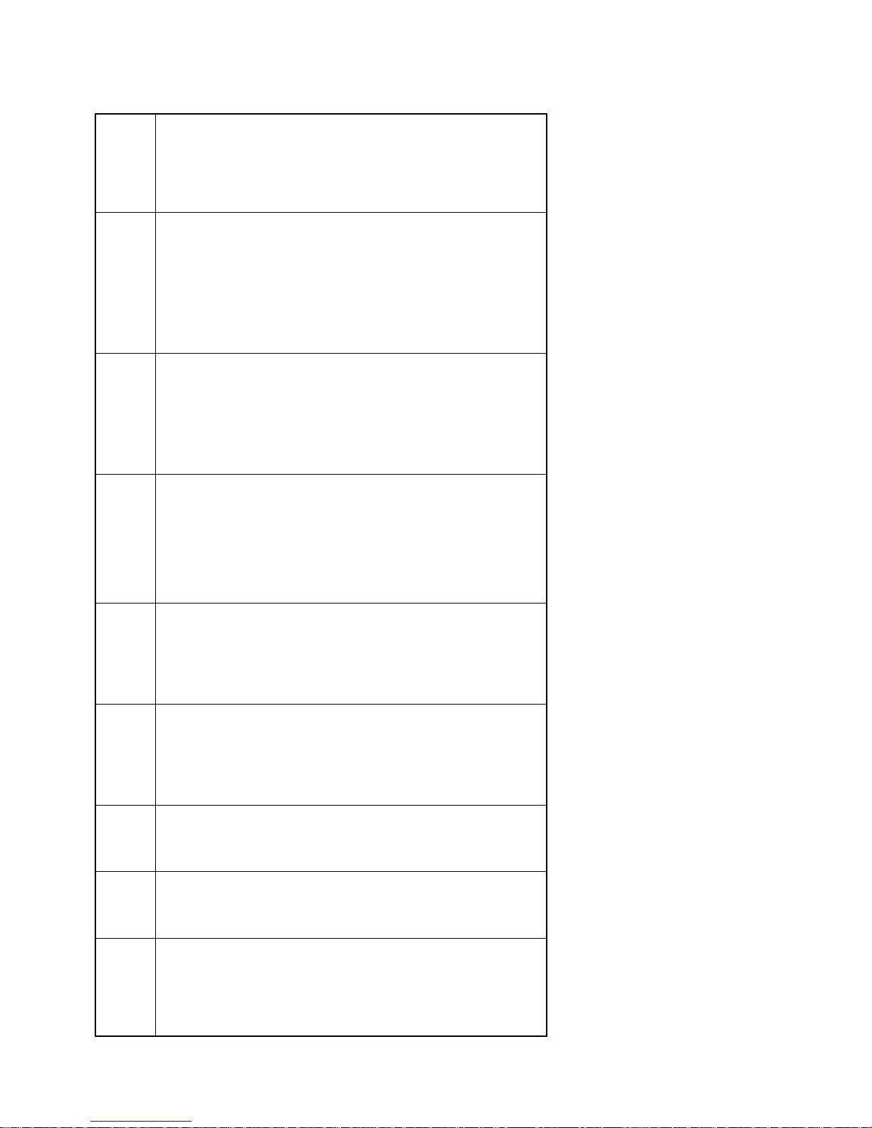
MODEL DECODING
CONDENSER COIL
VICTAULIC CONN.
(OPTIONAL)
A : STANDARD WITH
B : FLANGE CONN.
CIRCUIT
BREAKER
COMPRESSOR
A : STANDARD
B :
PRE-COATED
ALUMINUM FIN
ALUMINUM FIN
A :
B :
C : COPPER FIN
WITH VICTAULIC
CONN. (OPTIONAL)
C : ASME STAMPED
BELOW)
(SEE NOTE # 1
WITH FLANGE
CONN.(OPTIONAL)
D : ASME STAMPED
- COOLER GUARD
- UNIT DISCONNECT SWITCH
- COMPRESSOR ENCLOSURE
- WATER FLOW SWITCH
- SPRING ISOLATOR etc...
8
SUPPLY
( V-Ph-Hz )
ELECTRICAL
L : 380/415-3-50
(4 WIRE)
7
ANT
B : R-134a
REFRIGER-
4, 5 & 6
UNIT SIZE
BASIC
1, 2 & 3
045
ASQ
(SERIES)
050
055
060
COOLINE
AIR COOLED
070
SCREW WATER
080
090
100
CHILLERS
115
130
140
150
160
170
180
190
200
220
230
240
250
260
270
280
4
300
320
330
340
350
360
380
400
420
440
NOTES:
1. FOR OTHER COATING, SPECIFY YOUR REQUIREMENTS IN WRITING.
2. COMPUTER SELECTED DIGITS (FROM 'AA' TO 'ZZ') DESCRIBING OTHER OPTIONS & ACCESSORIES OR COMBINATIONS THEREOF, SUCH AS: - CONDENSER COIL GUARD
Page 5

FEATURES
These ASQ air cooled screw water chillers offer the ultimate combination of energy saving design, superior engineering
features and flexibility of application as required by today’s market.
These chillers incorporate the newest advanced microprocessor controller. This controller monitors analog and digital
*
inputs to achieve precise control & protective functions of the air cooled water chiller units. This microprocessor
controller is complete with all the hardware and software necessary to control the chiller unit and insures its efficiency
and reliability.
Designed to conform to ARI standard 550/590 water chilling packages using the vapor compression cycle.
*
Designed to conform to ANSI/ASHRAE 15-1994 Safety code for Mechanical Refrigeration.
*
Compact unit design and excellent serviceability.
*
All packaged chillers incorporate compact water coolers with enhanced inner grooved copper tubes bundled into a
*
"U" shaped and expanded into a steel tubular sheet which offer efficient water flow as well as heat transfer design
resulting in optimal unit performance.
High Energy Efficiency Ratio (EER) semi-hermetic compact twin screw compressors provided in these units.
*
Single point power connection to minimize job site installation cost and time.
*
Completely wired control panel with
*
safety controls.
Compressors are with part winding start.
*
Low noise condenser fans, direct drive at 860 RPM with rolled form venturi design to eliminate short circuiting of
*
airflow.
the advanced microprocessor
controller provides all the necessary operating and
All fans are die cast aluminum propeller type with aerodynamic design, top discharge, provided with protective
*
grille mounted on top panel within the unit casing.
All condenser fan motors are totally enclosed air over type (TEAO) with class ''F'' winding insulation and ball bearings.
*
Inherent thermal protection of the automatic reset type and specially designed for outdoor application.
STANDARD SPECIFICATIONS
CAPACITY CONTROL
A. Standard settings:
These chillers are equipped with stepless capacity control system as standard for very accurate response to load
requirements and best part load efficiency. Each compressor is equipped with a slider controller that enables to modulate
capacity between 25% to 100%, thus giving a broad range to control total chiller capacity between 10% to 100% on an
average. This system has following advantages:
1. Infinite capacity modulation allows the compressor capacity to exactly match the cooling load.
2. Reduce compressor cycling that leads to better operational reliability.
3. Reduce operating cost.
B. Optional settings:
The COOLINE packaged chillers incorporate stepped load shedding as required by some energy management systems.
Modulation of capacity in response to system load requirements is affected by a microprocessor controller which monitors the leaving water temperature.
Capacity control is achieved by cycling compressor ON/OFF and slider capacity pre-set control valve. The use of slider
control valve provides excellent part load capacities.
On multiple compressor units, capacity is controlled by a combination of slider capacity control valve and compressor
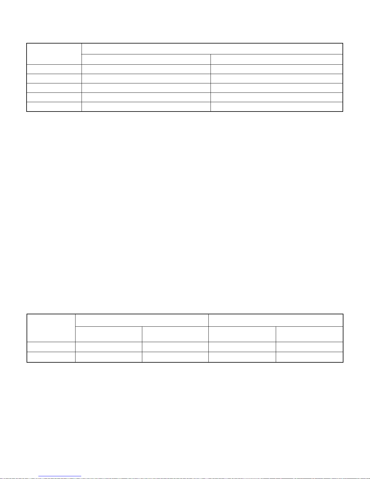
staging. For such optional stepped load shading, please see the following table.
5
Page 6
MODEL NUMBER
ASQ045B - ASQ070B
ASQ080B- ASQ150B
ASQ160B - ASQ200B
ASQ220B - ASQ280B
ASQ300B - ASQ440B
100-50-OFF
100-75-63-50-25-OFF
100-83-66-50-33-16-OFF
100-87-75-63-50-37-25-12-OFF
100-92-83-75-66-58-50-42-33-25-16-8-OFF
100-75-63-50-25-HGBP-OFF
100-83-66-50-33-16-HGBP-OFF
100-87-75-63-50-37-25-12-HGBP-OFF
100-92-83-75-66-58-50-42-33-25-16-8-HGBP-OFF
OPTION-2 OPTION-1
100-50-HGBP-OFF
NOTES: 1. All models have slider capacity control valve on all compressors.
2. HGBP = Hot gas bypass available on lead compressor for all models (option).
3. HGBP modulates to approximately 50% of its compressor lowest unloaded capacity.
SEMI-HERMETIC COMPACT TWIN SCREW COMPRESSORS
% FULL LOAD CAPACITY CONTROL
All compressors are compact semi-hermetic twin screw of the high capacity and efficiency due to its perfect profile form
ratio 5:6. Simple and robust construction with slider control valve for capacity unloading, suction/discharge shut-off valves,
check valve in discharge gas outlet, oil sight glass, oil fill/drain service valve, directly flanged-on three stage oil separator
with long-life fine filter 10 microns mesh size, robust axial bearings in tandem configuration, suction gas filter, internal
pressure relief valve and manual lock-out electronic protection system for thermal motor winding temperature, phase
reversal, discharge gas temperature protection controls.
CONDENSER COILS
W-configuration condenser coils are corrugated fin and tube type, constructed of seamless 3/8" dia. & 0.014" (0.35 mm)
thick copper tubes, mechanically bonded to aluminum fins for maximum heat transfer efficiency. As an option, copper
fins or acrylic coated aluminum fins or other coated coils may be provided. The fins have full self spacing collars
which completely cover each tube. The staggered tube design improve the thermal efficiency. End plates support
sheets are 14 gauge galvanized steel, formed to provide structural strength. Each coil is pressure tested in the factory
at not less than 450 psi air pressure.
COMPACT DESIGN SHELL AND TUBE WATER COOLERS
The DX shell & tube cooler with removable ‘U’ shaped bundled tubes are made of internally grooved copper tubes
expanded into a heavy steel tubular sheets.
The chiller cooler & baffles are constructed of steel and brass respectively. The coolers are insulated with heavy closed
cellular foam insulation (3/4" thick). All chiller barrels are fitted with vent, drain connection and victaulic water pipe
connection as standard.
SHELL & TUBE
HEAT
EXCHANGER
(COOLER)
DESIGN PRESSURE,
(BAR/PSIG)
16/235 22.8/335 29/426 41.5/610STD
10/147 11.3/165 15.5/228 23.3/342ASME (option)
WATER SIDE REFRIGERANT SIDE
TEST PRESSURE,
(BAR/PSIG)
DESIGN PRESSURE,
(BAR/PSIG)
TEST PRESSURE,
(BAR/PSIG)
CABINET
All units are of heavy gauge (G-90) galvanized steel. Steel sheet panels are zinc coated and galvanized by hot dip
process of lock-forming quality conforming to ASTM A 653 commercial weight G-90 followed by air dry paint or backed on
electrostatic polyester dry powder coat.
CONTROL PANEL
The control panel design is equivalent to NEMA 4 (IP55) with hinged door for easy access ensuring dust and weather-
proof construction. Internal power and control wiring is neatly routed, adequately anchored and all wires identified with
cable markers as per NEC standards applicable to HVAC industry.
The electrical controls used in the control panel are UL approved which are reliable in operation at high ambient conditions for a long period.
6
Page 7

CONDENSER FANS
Condenser fans, the impeller and motors are so constructed to form an integral unit. All fan motors shall be three phase
with class ''F'' winding insulation and ball bearings for high ambient application. These fan motors are of totally enclosed
air over type (TEAO) with inherent thermal protection of automatic reset type.
MICROPROCESSOR CONTROLLER
The microprocessor controller works on the state of art microprocessor technology. This controller monitors analog and
digital inputs to achieve precise control & safety functions of the unit.
The Software works on the Proportional Integral Derivative (PID) algorithm for precise control logic.
The simple to use push button keyboard allows accessing to the operating conditions, control set points & alarm history
that are clearly displayed on a multi-line back illuminated LCD panel.
An easy to install serial port/modem option allows remote monitoring of the operating parameters. With corresponding
windows software, the system allows data to be viewed in tabular or graphic format as well as interact with system set up.
This chiller controller is compatible with the Building Management System (BMS) BACNET/MODBUS protocols through
corresponding optional gateway interfaces.
It is also compatible with GSM protocol through GSM optional gateway that sends up to 3 mobile phone SMS messages
whenever alarm take place, indicating the type of alarm, the corresponding compressor, the related chiller and which
location.
The microprocessor consists of the following hardware:
1. User Interface Board: Provided with simple to use push button keyboard and menu driven software to access operating conditions, control set points & alarm history that are clearly displayed on the LCD panel.
2. Main Board: This controls up to two (2) compressor system.
3. Auxiliary Boards: Required for controlling an additional two (2) or more compressors.
4. Remote Monitoring System [Optional]: The micro controller is complete with all hardware and software necessary to
remotely monitor and control the chiller unit.
Display Information:
In the normal operating mode the 20 x 4 characters LCD panel display the system status, the temperature of the water
inlet & outlet, the set point, run time of the compressor & the alarm history.
Easily accessible measurements for each circuit include the following:
Suction and discharge temperatures
·
Suction, discharge and oil pressures
·
Water inlet/outlet temperatures
·
Compressor status
·
Fan status
·
Liquid line solenoid status
·
Unit/Compressor run time
·
The control temperature is continuously displayed on the 3 Digit 7 segments LED Display. The 3 LED lights indicate the
Power ON, Menu adjustment and Fault.
System Protection:
The following system protection is provided to ensure system reliability:
compressor winding overheating
·
Low suction pressure
·
High discharge pressure
·
Freeze protection
·
Low oil pressure
·
Sensor error
·
Time delay – Anti recycle time for compressor
·
Serial communication error
·
7
Page 8

STANDARD CONTROL & SAFETY DEVICES
MICROPROCESSOR CONTROLLER: This controller monitors analog and digital inputs to achieve precise control &
safety functions of the unit.
COMPRESSOR IN-BUILT PROTECTION DEVICE: Protect the compressor by monitoring:
A) Motor winding temperature in case of overload.
B) Discharge gas temperature in case of overheating.
C) Phase reversal for direction of rotation.
STARTERS: The starter is operated by the control circuit and provides power to the compressor motors. These devices
are rated to handle safely both RLA and LRA of motors.
CRANKCASE HEATERS: Each compressor has immersion type crankcase heater. The compressor crankcase heater is always on when
the compressors are de-energized. This protect the system against refrigerant migration, oil dilution and potential compressor failure.
HIGH PRESSURE SWITCH: This switch provides an additional safety protection in the case of excessive discharge pressure.
STANDARD ACCESSORIES
UNIT ON-OFF SWITCH: ON-OFF switch is provided for manually switching the unit control circuit.
INDICATOR LIGHTS: LED lights indicates power ON to the units, MENU adjustment and FAULT indications due to trip on safety devices.
ELECTRONIC EXPANSION VALVE: Electronic expansion valve is used to regulate the refrigerant flow to the water
cooler and maintain a constant superheat and load optimization.
FILTER DRIER (REPLACEABLE CORE TYPE): Refrigerant circuits are kept free of harmful moisture, sludge, acids
and oil contaminating particles by the filter drier.
SIGHT GLASS: A moisture indicating sight glass installed in the liquid line. An easy-to-read color indicator shows
moisture contents and provides a mean for checking the system refrigerant charge.
LIQUID LINE SOLENOID VALVE: Closes when the compressor is off to prevent any liquid refrigerant from accumulating
in the water cooler during the off cycle.
UNDER VOLTAGE AND PHASE PROTECTION: Protects against low incoming voltage as well as single phasing, phase reversal
and phase imbalance by de-energizing the control circuit. It is an automatic reset device, but it can be set up for manual reset.
OPTIONS
(All options are at extra cost. Please check with your nearest dealer/sales office)
HOT GAS BYPASS SYSTEM: Hot gas bypass is provided on the lead circuit to permit operation of the system down to 50%
of its unloaded capacity. Under low ambient condition, it controls temperature by eliminating the need to cycle the compressor
on and off, ensuring narrow temperature swing and lengthen the life span of the compressor.
WATER FLOW SWITCH: Paddle type field adjustable flow switch for water cooler circuits. Interlock into unit safety
circuits so that the unit will remain off until water flow is determine.
UNIT MOUNT SPRING ISOLATORS: This housed spring assemblies have a neoprene friction pad on the bottom to
prevent vibration transmission.
COMPRESSOR CIRCUIT BREAKERS: Protects against compressor branch circuit fault. When tripped (manually or
automatically), the breaker opens the power supply to the compressor and control circuit through auxiliary contacts.
LIQUID COOLERS: ASME code stamped liquid cooler.
PRESSURE GAUGES: Suction & discharge pressures gauges.
NON-FUSED MAIN DISCONNECT SWITCHES: De-energize power supply during servicing/repair works as well as with door interlock.
CONDENSER COIL GUARD: Protect the condenser coil from physical damage.
COMPRESSOR/COOLER GUARD: Protect the compressor from vandalism.
COMPRESSOR ENCLOSURE BOX: Reduce compressor operating noise and keep the compressor clean.
FLANGED COOLER CONNECTION: Easy on-site piping connections.
COOLER HEATER WRAPPED: Prevent freezing up of water on low ambient temperature.
COPPER FINS/TUBES CONDENSER COILS: For seashore salty corrosive environments.
COATED COPPER/ALUMINUM FINS CONDENSER COILS: For seashore or acid corrosive environments.
BMS: BACNET, MODBUS, GSM and remote monitoring.
8
Page 9
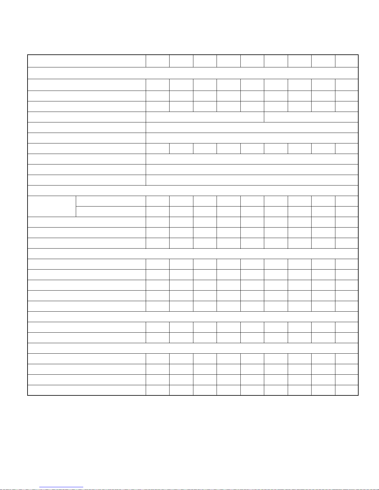
PHYSICAL DATA
UNIT SIZE
ASQ045B ASQ050B ASQ055B ASQ060B ASQ070B ASQ080B ASQ090B ASQ100B ASQ115B
COMPRESSOR
PART NUMBER
NUMBER OF COMPRESSORS 1 1 1 1 1 2 2 2 2
OIL CHARGE PER COMPRESSOR, Liters
CAPACITY CONTROL (STEPLESS) % 100-50 100-25
MOTOR OVERLOAD PROTECTION (INTERNAL) ELECTRONIC
OIL LUBRICATION INJECTION
TOTAL CRANKCASE HEATER WATTS 200 200 300 300 300 400 400 600 600
REFRIGERANT R-134a
EXPANSION VALVE DEVICE ELECTRONIC EXPANSION VALVE
CONTROL VOLTAGE 220V-1Ph-50Hz
800-683-15 800-683-15 800-683-18 800-683-21 800-683-24
15 15 22 22 22 15 15 22 22
800-683-15 (2) 800-683-15 (2) 800-683-18 (2) 800-683-21 (2)
CONDENSER
CONDENSER COIL Tube Dia.- Rows - Fins per inch 3/8–2–14 3/8–2–14 3/8–3–14 3/8–3–14 3/8–4–14 3/8–3–14 3/8–4–14 3/8–4–14 3/8–4–14
Total face area, Sq. ft. 87.5 87.5 87.5 87.5 87.5 100.1 100.1 100.1 140
AIRFLOW, CFM 38040 38040 36784 36784 41240 59400 55152 55152 75264
NUMBER OF FAN/FAN DIA., mm 4/762 4/762 4/762 4/762 4/800 6/800 6/800 6/800 8/800
FAN MOTOR RPM @ 380-3-50 915 915 915 915 860 860 860 860 860
COOLER
COOLER PART NUMBER
SHELL DIAMETER, mm 273 273 273 273 273 273 324 324 324
LENGTH, mm 1850 1850 1850 1850 1850 1850 2180 2180 2697
TOTAL WATER HOLDING VOLUME, Liters 53.2 53.2 53.2 53.2 53.2 53.2 99.8 99.8 113.5
WATER IN/OUT PIPE DIA. mm 100 100 100 100 100 100 150 150 150
800-660-91 800-660-91 800-660-91 800-660-91 800-660-91 800-660-92 800-659-05 800-659-05 800-660-52
ECONOMIZER
PART NUMBER N.A.
EXPANSION DEVICE N.A. T.E.V. N.A. N.A. N.A. N.A. T.E.V. N.A. N.A.
800-516-33
N.A. N.A. N.A. N.A.
800-516-33 (2)
N.A. N.A.
GENERAL
NUMBER OF REFRIGERANT CIRCUITS
REFRIGERANT CHARGE PER COMP., kg (COMP. 1/2)
SOUND PRESSURE LEVEL, dBA (3m./5m./10m.)
OPERATING/SHIPPING WEIGHTS, kg
NOTES: 1. All compressors with slider control valve unloading.
2. All compressors operate at 2900 RPM @ 50Hz.
3. Cooler vent and drain size are 1/2" MPT.
4. All coolers are single face refrigerant connection.
5. Sound pressure level : ±2dBA.
111112222
27 30 35 38 44 27 30 35 38
72.2/68.7/63.4 72.2/68.7/63.4 72.3/68.8/63.5 75.4/71.9/66.6 75.6/72.1/66.8 74.5/71/65.7 74.5/71/65.7 74.6/71.1/65.8 78.4/74.9/69.6
2038/1985 2048/1995 2442/2389 2456/2403 2575/2522 3104/3051 3335/3235 4026/3926 4640/4527
9
Page 10
PHYSICAL DATA
UNIT SIZE
ASQ130B ASQ140B ASQ150B ASQ160B ASQ170B ASQ180B ASQ190B ASQ200B ASQ220B
COMPRESSOR
PART NUMBER
NUMBER OF COMPRESSORS 2 2 2 3 3 3 3 3 4
OIL CHARGE PER COMPRESSOR, Liters
CAPACITY CONTROL (STEPLESS) % 100-25 100-16.3 100-12.5
MOTOR OVERLOAD PROTECTION (INTERNAL) ELECTRONIC
OIL LUBRICATION INJECTION
TOTAL CRANKCASE HEATER WATTS 600 600 600 900 900 900 900 900 1200
REFRIGERANT R-134a
EXPANSION VALVE DEVICE ELECTRONIC EXPANSION VALVE
CONTROL VOLTAGE 220V-1Ph-50Hz
800-683-24 (2) 800-683-24 (2) 800-683-24 (2) 800-683-18 (3) 800-683-18 (3) 800-683-21 (3) 800-683-21 (3) 800-683-24 (3)
22 22 22 22 22 22 22 22 22
800-683-21
800-683-18
CONDENSER
CONDENSER COIL Tube Dia.- Rows - Fins per inch 3/8–4–14 3/8–3–14 3/8–4–14 3/8–3–14 3/8–4–14 3/8–4–14 3/8–4–14 3/8–3–14
Total face area, Sq. ft. 140 175 175 210 210 210 210 210 304
AIRFLOW, CFM 75264 100860 94080 121032 115488 112896 112896 112896 166240
NUMBER OF FAN/FAN DIA., mm 8/800 10/800 10/800 12/800 12/800 12/800 12/800 12/800 16/800
3/8–4–14
3/8–3–14
(2)
(2)
FAN MOTOR RPM @ 380-3-50 860 860 860 860 860 860 860 860 860
COOLER
COOLER PART NUMBER
SHELL DIAMETER, mm 324 406 406 406 406 406 406 406 324
LENGTH, mm 2697 2744 2744 2737 2737 2737 2737 2737 2697
TOTAL WATER HOLDING VOLUME, Liters 113.5 221.7 221.7 206.5 206.5 206.5 184.4 184.4 227
WATER IN/OUT PIPE DIA. mm 150 200 200 200 200 200 200 200 150
800-660-52 800-660-55 800-660-55
800-660-59 800-660-59 800-660-59 800-660-62 800-660-62 800-660-52 (2)
ECONOMIZER
PART NUMBER N.A. N.A.
EXPANSION DEVICE N.A. N.A. T.E.V. N.A. T.E.V. T.E.V. T.E.V. N.A. N.A.
800-516-33 (2)
N.A.
800-516-33 (2) 800-516-33 (2) 800-516-33 (3)
N.A. N.A.
GENERAL
NUMBER OF REFRIGERANT CIRCUITS
REFRIGERANT CHARGE PER COMP., kg (COMP. 1/2)
SOUND PRESSURE LEVEL, dBA (3m./5m./10m.)
OPERATING/SHIPPING WEIGHTS, kg
NOTES: 1. All compressors with slider control valve unloading.
2. All compressors operate at 2900 RPM @ 50Hz.
3. Cooler vent and drain size are 1/2" MPT.
4. All coolers are single face refrigerant connection.
5. Sound pressure level : ±2dBA.
222333334
44 44 48 35 39/35 41/38 41/38 44 38/35
78.6/75.1/69.8 78.9/75.4/70.1 78.9/75.4/70.1 77.1/73.6/68.3 77.1/73.6/68.3 80.2/76.7/71.4 80.2/76.7/71.4 80.4/76.9/71.6 80.1/76.6/71.4
4675/4562 5277/5055 5423/5201 6797/6591 6920/6714 7007/6801 7041/6857 7051/6867 9130/8903
10
Page 11
PHYSICAL DATA
UNIT SIZE
ASQ230B ASQ240B ASQ250B ASQ260B ASQ270B ASQ280B ASQ300B ASQ320B ASQ330B
COMPRESSOR
PART NUMBER
800-683-21 (4) 800-683-24 (4) 800-683-24 (4)
800-683-21
(3)
800-683-21
(2)
(2)
800-683-21
(2)
800-683-18
(4)
800-683-15
(2)
800-683-18 (6) 800-683-18 (6)
800-683-24
(1)
800-683-24
(2)
800-683-24
NUMBER OF COMPRESSORS 4 4 4 4 4 4 6 6 6
OIL CHARGE PER COMPRESSOR, Liters
22 22 22 22 22 22 22/15 22 22
CAPACITY CONTROL (STEPLESS) % 100-12.5 100-8.3
MOTOR OVERLOAD PROTECTION (INTERNAL) ELECTRONIC
OIL LUBRICATION INJECTION
TOTAL CRANKCASE HEATER WATTS 1200 1200 1200 1200 1200 1200 1600 1800 1800
REFRIGERANT R-134a
EXPANSION VALVE DEVICE ELECTRONIC EXPANSION VALVE
CONTROL VOLTAGE 220V-1Ph-50Hz
CONDENSER
CONDENSER COIL Tube Dia.- Rows - Fins per inch 3/8–3–14 3/8–4–14 3/8–4–14 3/8–4–14 3/8–4–14 3/8–4–14 3/8–4–14
3/8–4–14
3/8–3–14
Total face area, Sq. ft. 304 304 304 304 304 304 430.7 430.7 430.7
AIRFLOW, CFM 166240 163616 156192 156192 156192 156192 194004 191160 191160
NUMBER OF FAN/FAN DIA., mm 16/800 16/800 16/800 16/800 16/800 16/800 18/800 18/800 18/800
3/8–4–14
3/8–3–14
FAN MOTOR RPM @ 380-3-50 860 860 860 860 860 860 860 860 860
COOLER
COOLER PART NUMBER
SHELL DIAMETER, mm 324 324 324 406 406 406 406 406 406
LENGTH, mm 2697 2697 2697 2744 2744 2744 2737 2737 2737
TOTAL WATER HOLDING VOLUME, Liters 227 227 227 443.4 443.4 443.4 413 413 413
WATER IN/OUT PIPE DIA. mm 150 150 150 200 200 200 200 200 200
800-660-52 (2) 800-660-52 (2) 800-660-52 (2) 800-660-55 (2) 800-660-55 (2) 800-660-55 (2) 800-660-59 (2) 800-660-59 (2) 800-660-59 (2)
ECONOMIZER
PART NUMBER N.A. N.A. N.A. N.A. N.A. N.A.
EXPANSION DEVICE N.A. N.A. N.A. N.A. N.A. N.A. T.E.V. T.E.V. T.E.V.
800-516-33 (2) 800-516-33 (2) 800-516-33 (3)
GENERAL
NUMBER OF REFRIGERANT CIRCUITS
REFRIGERANT CHARGE PER COMP., kg (COMP. 1/2)
SOUND PRESSURE LEVEL, dBA (3m./5m./10m.)
OPERATING/SHIPPING WEIGHTS, kg
NOTES: 1. All compressors with slider control valve unloading.
2. All compressors operate at 2900 RPM @ 50Hz.
3. Cooler vent and drain size are 1/2" MPT.
4. All coolers are single face refrigerant connection.
5. Sound pressure level : ±2dBA.
444444666
38 44/38 44/38 44/38 44 48/44 35/30 39/35 39/35
81.4/77.9/72.6 81.5/77.9/72.7 81.5/77.9/72.7 81.5/77.9/72.7 81.6/78.1/72.8 81.6/78.1/72.8 79.4/75.8/70.6 79.4/75.8/70.6 79.4/75.8/70.6
9159/8932 9227/9000 9394/9167 9986/9543 10021/9578 10052/9609 13088/12675 13242/12829 13257/12844
11
Page 12
PHYSICAL DATA
UNIT SIZE
ASQ340B ASQ350B ASQ360B ASQ380B ASQ400B ASQ420B ASQ440B
COMPRESSOR
800-683-24
PART NUMBER
NUMBER OF COMPRESSORS 6 6 6 6 6 6 6
OIL CHARGE PER COMPRESSOR, Liters
CAPACITY CONTROL (STEPLESS) % 100-8.3
MOTOR OVERLOAD PROTECTION (INTERNAL) ELECTRONIC
OIL LUBRICATION INJECTION
TOTAL CRANKCASE HEATER WATTS 1800 1800 1800 1800 1800 1800 1800
REFRIGERANT R-134a
EXPANSION VALVE DEVICE ELECTRONIC EXPANSION VALVE
CONTROL VOLTAGE 220V-1Ph-50Hz
800-683-21 (6) 800-683-21 (6) 800-683-21 (6) 800-683-24 (6) 800-683-24 (6) 800-683-24 (6)
22 22 22 22 22 22 22
(4)
800-683-21
(2)
CONDENSER
CONDENSER COIL Tube Dia.- Rows - Fins per inch 3/8–4–14 3/8–4–14 3/8–4–14 3/8–4–14 3/8–4–14 3/8–4–14 3/8–4–14
Total face area, Sq. ft. 430.7 521.3 521.3 521.3 521.3 521.3 521.3
AIRFLOW, CFM 191160 232936 232936 232936 232936 232936 269038
NUMBER OF FAN/FAN DIA., mm 18/800 22/800 22/800 22/800 22/800 22/800 22/800
FAN MOTOR RPM @ 380-3-50 860 860 860 860 860 860 860
COOLER
COOLER PART NUMBER
SHELL DIAMETER, mm 406 406 406 406 406 457 457
LENGTH, mm 2737 2737 2737 2737 2737 2790 2790
TOTAL WATER HOLDING VOLUME, Liters 413 413 413 368.8 368.8 504 504
WATER IN/OUT PIPE DIA. mm 200 200 200 200 200 200 200
800-660-59 (2) 800-660-59 (2) 800-660-59 (2) 800-660-62 (2) 800-660-62 (2) 800-660-68 (2) 800-660-68 (2)
ECONOMIZER
PART NUMBER N.A. N.A.
EXPANSION DEVICE N.A. N.A. T.E.V. N.A. N.A. T.E.V. T.E.V.
800-516-33 (3)
N.A. N.A.
800-516-33 (3) 800-516-33 (6)
GENERAL
NUMBER OF REFRIGERANT CIRCUITS
REFRIGERANT CHARGE PER COMP., kg (COMP. 1/2)
SOUND PRESSURE LEVEL, dBA (3m./5m./10m.)
OPERATING/SHIPPING WEIGHTS, kg
NOTES: 1. All compressors with slider control valve unloading.
2. All compressors operate at 2900 RPM @ 50Hz.
3. Cooler vent and drain size are 1/2" MPT.
4. All coolers are single face refrigerant connection.
5. Sound pressure level : ±2dBA.
6666666
38 38 41/38 44/38 44 48/44 48
82.9/79.3/74.1 83.1/79.5/74.3 83.1/79.5/74.3 83.2/79.7/74.4 83.3/79.8/74.5 83.3/79.8/74.5 83.3/79.8/74.5
13297/12884 13859/13446 13902/13489 13971/13602 14006/13637 14597/14093 14643/14139
12
Page 13
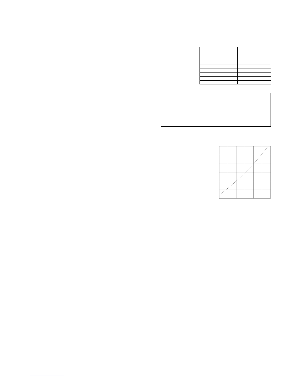
SELECTION PROCEDURE (English units)
DESIGN REQUIREMENTS
The following design requirements must be known to select a package chiller.
1. Required cooling capacity in tons
2. Leaving chilled water temperature in 0F (LCWT)
3. Chilled water flow rate in GPM
4. Chilled water cooling range in 0F (water in temp. _ water out temp.)
5. Design ambient temperature
6. Minimum ambient temperature
7. Altitude
8. Electrical power supply
SAMPLE SELECTION
Select an Air Cooled Packaged chiller for the following conditions:
Required system capacity is 110 tons at 540F entering chilled water
and 440F leaving water. Design ambient temperature is 950F.
Altitude is 2000 feet above sea level.
Water cooler fouling factor is 0.00010. Power supply: 380/415V-3Ph-50Hz.
STEP-1: UNIT SELECTION
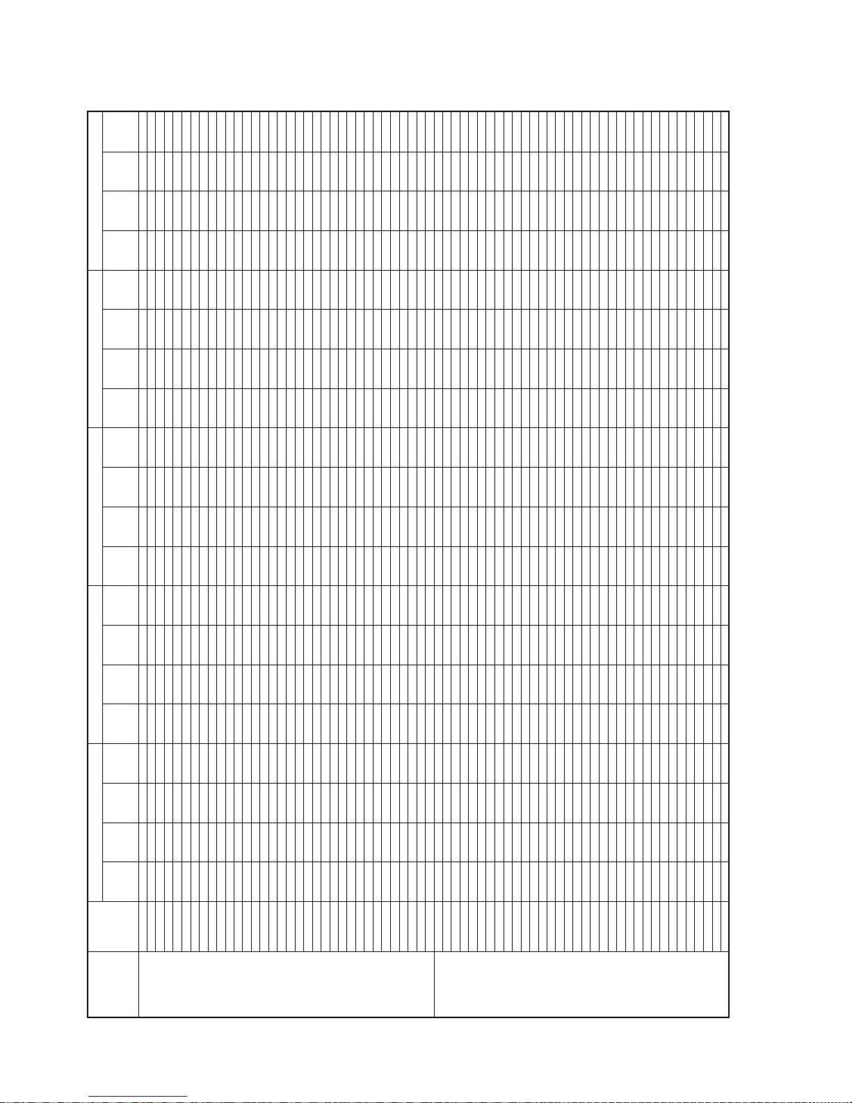
Entering the capacity performance data at given LCWT and ambient temperature.
ASQ115B chiller unit at sea level will produce 115.3 tons and 120.3 kW compressor
0
power input at 44
F leaving chilled water temperature with 100F water temperature
difference and 950F ambient temperature.
For the conditions required, the unit actual cooling capacity when corrected for
altitude (0.99) and fouling factor (1.0).
Capacity = 115.3x0.99x1.0 = 114.1 Tons, which then exceeds the requirements.
So the selection is correct.
STEP-2: CHILLED WATER FLOW (GPM):
Water GPM =
Required capacity (Tons) x 24 = 110 x 24
Cooling Range, ∆T 100F
= 264 GPM
EVAPORATOR FOULING
FACTOR (HR-FT
2-0
0.00010
0.00025
0.00050
0.00075
0.00100
ELEVATION ABOVE
SEA LEVEL (FT.)
CAPACITY
CORRECTION
F/BTU)
FACTOR
1.000
0.992
0.978
0.965
0.951
TABLE - 2
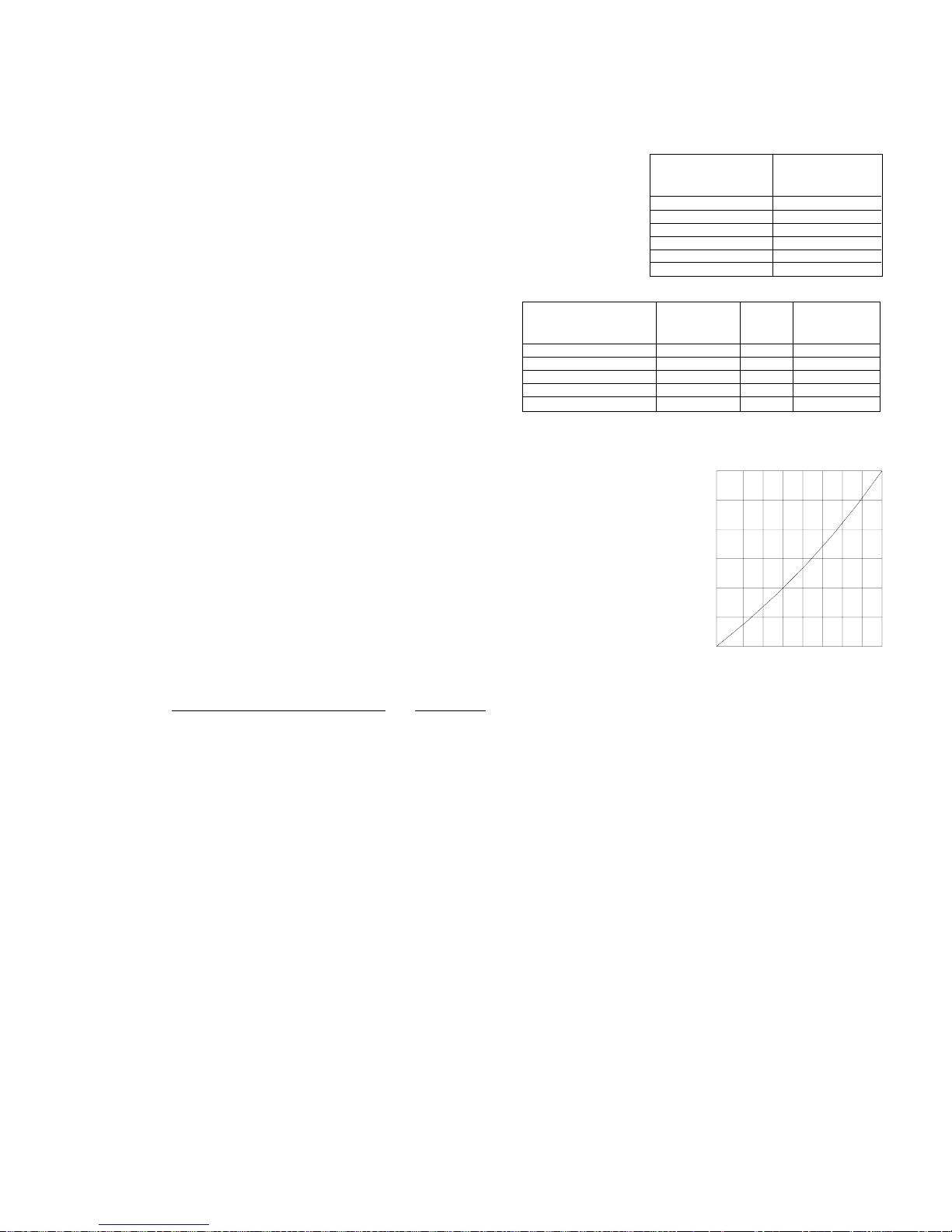
+0.6
F)
0
+0.4
+0.2
CORRECTION FACTOR (
-0.2
-0.4
CAPACITY
CORRECTION
FACTOR
0
2000
4000
6000
8000
10000
1.00
0.99
0.98
0.97
0.96
0.95
TABLE - 1
POWER
INPUT
FACTOR
1.000
0.997
0.990
0.984
0.978
0
510
CHILLED WATER TEMPERATURE RISE (0F)
STANDARDS
ARI-550/590-98
ARI-590-86
ARI-590-81
15 20
TABLE - 3
ARI
Referring to pressure drop chart (page # 22), pressure drop at 264 GPM = 13.3 ft. of water for selected model.
NOTE: The total flow rate should be divided by 2 for models ASQ220B - ASQ440B to find out the total pressure drop.
STEP-3: ELECTRICAL
Refer to electrical data at
380/415V-3Ph-50Hz
, the main power wire size for ASQ115B is to be sized for a minimum circuit
ampacity (MCA) of 292 Amps and maximum over current protection (MOCP) of 411 Amps.
STEP-4: CHILLED WATER PUMP SELECTION
For chilled water pump selection, add all pressure drop in the closed chilled water loop piping to the pressure drop
calculated in step 2.
STEP-5: LCWT CORRECTION
Refer to table-3: Add correction factor to design leaving chilled water temperature (LCWT) when chilled water tempera-
0
ture range is above 10
F and subtract correction from design leaving chilled water temperature (LCWT) when water
temperature range is below 100F.
EXAMPLE:
0
If LCWT rise is 12.5
F, enter correction curve at 12.50F and read the correction factor of 0.2. The corrected LCWT is
44+0.2 = 44.20F.
NOTE: 1.When the chilled water temperature rise is less than 50F, the high water flow rate will result to excessive
pressure drop. In such cases, contact factory for special selection of a cooler with wider baffle spacing.
2.Please refer to water pressure drop curves.
13
Page 14
SELECTION PROCEDURE (Metric units)
DESIGN REQUIREMENTS
The following design requirements must be known to select a proper package chiller.
1. Required cooling capacity in kilowatt (kW)
2. Leaving chilled water temperature in 0C (LCWT)
3. Chilled water flow rate in LPS
4. Chilled water cooling range in 0C (water in temp. _ water out temp.)
5. Design ambient temperature
6. Minimum ambient temperature
7. Altitude
8. Electrical power supply
SAMPLE SELECTION
Select an Air Cooled Packaged chiller for the following conditions:
Required system capacity is 395 kW at 120C entering chilled water
and 60C leaving water. Design ambient temperature is 350C.
EVAPORATOR FOULING
FACTOR (M
0.000018
0.000044
0.000088
0.000132
0.000176
Altitude is 600 meter above sea level.
Water cooler fouling factor is 0.000018. Power supply:
380/415V-3Ph-50Hz.
2-0
ELEVATION ABOVE
SEA LEVEL (Meter)
CAPACITY
C/W)
CORRECTION
FACTOR
TABLE - 2
1.000
0.992
0.978
0.965
0.951
0
600
1200
1800
2400
3000
TABLE - 1
POWER
INPUT
FACTOR
STEP-1: UNIT SELECTION
Entering the capacity performance data at given LCWT and ambient temperature.
ASQ115B chiller unit at sea level will produce 403.6 kW and 120.1 kW compressor
0
power input at 6
C leaving chilled water temperature with 60C water temperature
difference and 350C ambient temperature.
0
C)
+0.33
+0.22
+0.11
For the conditions required, the unit actual cooling capacity when corrected for
altitude (0.99) and fouling factor (1.0).
CORRECTION FACTOR (
Capacity = 403.6x0.99X1.0 = 399.5 kW, which then exceeds the requirements.
So the selection is correct.
STEP-2: CHILLED WATER FLOW (LPS):
Water LPS =
Required capacity (kW) x 0.239 = 395 x 0.239
Cooling Range, ∆T 60C
= 15.7 LPS
-0.11
-0.22
CHILLED WATER TEMPERATURE RISE (0C)
TABLE - 3
Referring to pressure drop chart (page # 22), pressure drop at 15.7 LPS = 36 kPa for selected model.
NOTE: The total flow rate should be divided by 2 for models ASQ220B - ASQ440B to find out the total pressure drop.
CAPACITY
CORRECTION
FACTOR
1.00
0.99
0.98
0.97
0.96
0.95
STANDARDS
1.000
ARI-550/590-98
0.997
0.990
0.984
0.978
54 6780109
ARI-590-86
ARI-590-81
ARI
STEP-3: ELECTRICAL
Refer to electrical data at
380/415V-3Ph-50Hz
ampacity (MCA) of 292 Amps and maximum over current protection (MOCP) of 411 Amps.
STEP-4: CHILLED WATER PUMP SELECTION
For chilled water pump selection, add all pressure drop in the closed chilled water loop piping to the pressure drop
calculated in step 2.
STEP-5: LCWT CORRECTION
Refer to table-3: Add correction factor to design leaving chilled water temperature (LCWT) when chilled water tempera-
0
ture range is above 6
C and subtract correction from design leaving chilled water temperature (LCWT) when water
temperature range is below 60C.
EXAMPLE:
0
If LCWT rise is 7.4
C, enter correction curve at 7.40C and read the correction factor of 0.11. The corrected LCWT is
60C+0.11 = 6.110C.
NOTE: 1.When the chilled water temperature rise is less than 3
pressure drop. In such cases, contact factory for special selection of a cooler with wider baffle spacing.
2.Please refer to water pressure drop curves.
, the main power wire size for ASQ115B is to be sized for a minimum circuit
0
C, the high water flow rate will result to excessive
14
Page 15
F AMBIENT TEMPERATURE
0
F AMBIENT TEMPERATURE 130
0
F AMBIENT TEMPERATURE 125
0
WATER
COMP.
CAP.
WATER
COMP.
CAP.
WATER
COMP.
CAP.
FLOW
(GPM)
EER
kW
(Tons)
FLOW
(GPM)
EER
kW
(Tons)
FLOW
(GPM)
EER
kW
(Tons)
4. Direct interpolation is permissible. Do not extrapolate.
5. kW power input is for compressor only.
6. EER for entire unit. Refer to electrical data for fan kW.
PERFORMANCE DATA (English units)
F AMBIENT TEMPERATURE 115
0
F AMBIENT TEMPERATURE 105
0
95
LEAVING
FLOW
(GPM)
WATER
EER
kW
COMP.
CAP.
(Tons)
FLOW
(GPM)
WATER
EER
kW
COMP.
CAP.
(Tons)
SIZE
UNIT
(LCWT)
CHILLED
WATER TEMP.
ASQ 045B 39.5 41.7 10.3 94.7 37.0 46.3 8.8 88.8 34.4 51.8 7.4 82.6 31.7 58.1 6.1 76.1 30.3 61.5 5.5 72.7
ASQ 050B 41.7 46.1 9.9 100.1 39.8 52.7 8.4 95.6 37.8 60.4 7.0 90.6 35.5 69.3 5.8 85.1 34.2 74.2 5.2 82.1
ASQ 055B 47.3 50.6 10.3 113.6 44.4 56.8 8.7 106.4 41.2 64.1 7.2 99.0 38.0 72.3 5.9 91.1 36.3 76.8 5.4 87.0
ASQ 060B 51.4 59.3 9.7 123.4 48.0 65.8 8.2 115.3 44.4 73.1 6.9 106.5 40.4 81.1 5.7 97.0 38.3 85.4 5.1 92.0
ASQ 070B 59.1 68.6 9.6 141.9 55.7 76.7 8.2 133.7 52.1 85.5 6.9 125.0 48.2 95.2 5.8 115.8 46.2 100.3 5.3 110.9
ASQ 080B 67.0 80.9 9.0 160.9 63.1 90.7 7.7 151.5 58.9 102.4 6.4 141.5 54.5 115.9 5.3 130.7 52.1 123.3 4.8 125.0
ASQ 090B 84.2 92.8 10.0 202.2 80.3 105.9 8.5 192.8 76.0 121.3 7.0 182.4 71.2 139.1 5.8 170.9 68.6 148.9 5.3 164.7
ASQ 100B 92.5 109.1 9.5 222.0 86.2 122.5 7.9 206.8 79.5 137.8 6.5 190.9 72.5 155.2 5.3 174.1 68.9 164.6 4.8 165.4
ASQ 115B 110.7 118.4 10.3 265.6 103.2 131.0 8.7 247.7 95.2 145.2 7.3 228.5 86.7 160.8 6.1 208.0 82.2 169.2 5.5 197.3
ASQ 130B 123.7 145.9 9.5 296.8 115.9 162.6 8.0 278.2 107.7 180.8 6.8 258.5 99.1 200.6 5.6 237.7 94.6 211.2 5.1 226.9
ASQ 140B 129.9 142.5 10.0 311.8 121.8 158.8 8.5 292.3 113.2 176.7 7.1 271.7 104.2 196.2 6.0 250.0 99.5 206.5 5.4 238.8
ASQ 150B 139.7 152.5 10.1 335.3 133.8 174.5 8.5 321.1 127.3 199.5 7.2 305.5 120.2 227.4 6.0 288.5 116.4 242.5 5.5 279.3
ASQ 160B 146.9 154.7 10.3 352.6 137.3 173.3 8.7 329.6 127.2 194.9 7.2 305.4 116.6 219.5 5.9 279.9 111.1 232.9 5.4 266.8
ASQ 170B 158.0 169.7 10.2 379.1 150.0 194.4 8.6 360.0 141.4 223.3 7.1 339.4 132.1 256.7 5.8 317.1 127.2 275.0 5.2 305.3
ASQ 180B 171.9 198.0 9.6 412.7 162.4 225.1 8.1 389.9 151.9 256.3 6.7 364.5 140.2 291.4 5.5 336.4 133.9 310.4 4.9 321.3
ASQ 190B 176.2 209.8 9.4 422.8 167.6 241.7 7.8 402.3 157.9 278.7 6.4 378.9 146.9 320.7 5.2 352.5 140.8 343.6 4.7 338.0
0
ASQ 200B 182.0 217.4 9.4 436.8 170.9 242.4 7.9 410.1 159.0 269.7 6.7 381.7 146.5 299.5 5.6 351.6 140.0 315.3 5.1 336.0
F
40
ASQ 220B 210.0 222.6 10.3 504.1 196.0 247.8 8.7 470.5 181.2 276.3 7.3 434.8 165.4 308.4 6.0 397.0 157.2 325.6 5.4 377.3
ASQ 230B 219.1 240.6 10.0 525.7 204.0 266.3 8.5 489.7 187.9 294.9 7.1 451.0 170.8 326.4 5.9 409.8 161.8 343.3 5.3 388.3
ASQ 240B 226.8 252.0 10.0 544.4 211.7 279.5 8.4 508.1 195.5 310.1 7.1 469.2 178.3 343.6 5.9 427.9 169.3 361.5 5.3 406.4
ASQ 250B 236.6 259.7 10.1 567.8 221.4 288.8 8.6 531.4 205.3 320.9 7.2 492.6 188.1 356.0 6.0 451.4 179.1 374.8 5.4 429.9
ASQ 260B 243.4 262.5 10.3 584.1 227.3 291.4 8.7 545.6 210.3 323.4 7.3 504.8 192.4 358.5 6.1 461.7 183.0 377.2 5.5 439.2
ASQ 270B 257.1 290.3 9.9 617.1 240.8 323.4 8.4 577.8 223.5 359.5 7.0 536.5 205.4 398.9 5.9 493.0 196.0 419.8 5.3 470.5
ASQ 280B 265.2 307.2 9.7 636.4 250.7 346.8 8.2 601.8 235.3 390.7 6.9 564.7 218.7 439.2 5.7 525.0 210.1 465.2 5.2 504.1
ASQ 300B 282.9 296.7 10.6 679.1 266.0 334.0 8.9 638.5 248.1 377.6 7.4 595.5 229.1 427.4 6.1 549.8 219.1 454.7 5.5 526.0
ASQ 320B 303.2 328.1 10.3 727.7 285.5 371.9 8.7 685.3 266.8 423.0 7.2 640.2 246.8 481.3 5.9 592.2 236.3 513.2 5.3 567.0
ASQ 330B 308.0 338.1 10.2 739.2 291.1 385.4 8.5 698.7 273.0 440.6 7.1 655.3 253.6 503.8 5.8 608.6 243.3 538.5 5.2 584.0
ASQ 340B 320.6 363.3 9.9 769.4 298.3 402.2 8.4 716.0 274.4 445.5 7.0 658.6 248.9 493.1 5.8 597.5 235.6 518.5 5.2 565.5
ASQ 350B 331.1 345.5 10.6 794.7 309.4 382.6 9.0 742.5 285.9 424.4 7.6 686.2 260.8 470.7 6.3 626.0 247.6 495.6 5.7 594.3
ASQ 360B 343.6 374.5 10.2 824.6 324.2 423.1 8.6 778.0 302.8 478.7 7.2 726.7 279.3 541.4 5.9 670.3 266.7 575.4 5.3 640.2
ASQ 380B 356.7 396.4 10.1 856.1 334.9 441.7 8.5 803.8 311.6 491.6 7.2 747.8 286.8 546.3 6.0 688.3 273.8 575.5 5.4 657.2
ASQ 400B 369.1 423.3 9.8 885.9 347.1 472.5 8.3 833.1 323.7 526.3 7.0 776.8 298.8 585.0 5.8 717.2 285.9 616.2 5.3 686.1
ASQ 420B 406.6 457.6 10.0 975.8 384.5 516.4 8.5 922.7 360.8 581.9 7.1 866.0 335.5 654.2 5.9 805.3 322.2 693.0 5.4 773.4
ASQ 440B 419.3 484.0 9.8 1006.4 400.4 553.6 8.2 961.0 379.7 632.2 6.9 911.2 356.9 719.9 5.7 856.6 344.7 767.3 5.2 827.3
ASQ 045B 42.0 42.8 10.7 100.7 39.3 47.4 9.1 94.4 36.5 52.9 7.7 87.7 33.6 59.0 6.4 80.7 32.1 62.3 5.8 77.1
ASQ 050B 44.2 47.1 10.3 106.0 42.1 53.7 8.7 101.1 39.9 61.4 7.3 95.7 37.4 70.3 6.0 89.8 36.1 75.2 5.4 86.6
ASQ 055B 50.6 51.9 10.8 121.5 47.4 58.1 9.1 113.9 44.1 65.3 7.6 105.8 40.6 73.5 6.3 97.3 38.7 78.0 5.6 92.9
ASQ 060B 55.1 61.0 10.1 132.2 51.4 67.5 8.6 123.3 47.4 74.8 7.2 113.8 43.2 82.8 6.0 103.7 41.0 87.1 5.4 98.5
ASQ 070B 63.6 70.3 10.1 152.6 59.9 78.5 8.6 143.7 55.9 87.5 7.2 134.2 51.8 97.3 6.1 124.2 49.6 102.5 5.5 119.0
ASQ 080B 72.5 83.5 9.5 174.0 68.2 93.4 8.1 163.6 63.6 105.0 6.8 152.6 58.7 118.2 5.6 140.8 56.1 125.4 5.0 134.7
ASQ 090B 86.3 93.7 10.2 207.2 82.3 106.8 8.6 197.6 77.9 122.3 7.2 186.9 73.0 140.1 5.9 175.2 70.4 149.8 5.4 168.9
ASQ 100B 95.0 110.3 9.6 228.0 88.6 123.7 8.1 212.6 81.8 139.1 6.7 196.3 74.7 156.4 5.5 179.2 71.0 165.8 4.9 170.3
ASQ 115B 113.2 119.4 10.4 271.7 105.7 132.2 8.9 253.6 97.6 146.4 7.5 234.2 89.0 162.1 6.2 213.5 84.5 170.5 5.6 202.7
ASQ 130B 126.3 147.1 9.6 303.2 118.5 163.9 8.1 284.4 110.2 182.3 6.9 264.5 101.5 202.3 5.7 243.6 97.0 213.0 5.2 232.7
ASQ 140B 133.5 143.8 10.2 320.4 125.2 160.3 8.7 300.6 116.5 178.4 7.3 279.7 107.4 198.1 6.1 257.7 102.7 208.6 5.6 246.4
ASQ 150B 143.2 153.6 10.3 343.7 137.2 175.8 8.7 329.3 130.6 200.9 7.3 313.4 123.3 229.1 6.1 295.9 119.4 244.4 5.6 286.5
ASQ 160B 151.0 156.2 10.5 362.3 141.2 174.9 8.9 338.9 131.0 196.6 7.4 314.4 120.2 221.2 6.1 288.5 114.6 234.6 5.5 275.0
ASQ 170B 162.0 171.2 10.4 388.8 154.0 196.0 8.7 369.5 145.2 225.1 7.2 348.6 135.8 258.4 5.9 325.8 130.7 276.7 5.4 313.7
ASQ 180B 176.2 199.8 9.8 422.9 166.6 227.1 8.2 399.7 155.8 258.5 6.8 373.9 143.9 293.8 5.6 345.3 137.5 312.9 5.0 329.9
189.0 220.4 9.6 453.6 177.5 245.7 8.1 425.9 165.3 273.4 6.9 396.6 152.4 303.6 5.7 365.7 145.7 319.7 5.2 349.6
ASQ 190B 182.6 212.5 9.6 438.2 173.7 244.8 8.0 416.8 163.5 282.1 6.6 392.4 152.0 324.3 5.4 364.8 145.7 347.3 4.8 349.6
ASQ 200B
F
0
42
ASQ 220B 214.9 224.6 10.5 515.9 200.8 249.9 8.9 481.9 185.8 278.6 7.4 445.8 169.9 310.7 6.1 407.7 161.6 328.0 5.6 387.7
ASQ 230B 224.0 242.8 10.2 537.7 208.8 268.6 8.6 501.2 192.6 297.4 7.2 462.2 175.3 329.1 6.0 420.7 166.3 346.0 5.4 399.1
ASQ 240B 231.9 254.2 10.1 556.6 216.6 281.9 8.6 519.9 200.3 312.6 7.2 480.7 183.0 346.4 6.0 439.1 173.9 364.4 5.4 417.4
ASQ 250B 241.8 261.8 10.2 580.3 226.5 291.1 8.7 543.6 210.2 323.4 7.3 504.4 192.9 358.8 6.1 463.0 183.9 377.8 5.5 441.3
ASQ 260B 250.2 265.2 10.5 600.5 233.9 294.4 8.9 561.4 216.6 326.7 7.5 519.9 198.4 362.1 6.2 476.2 189.0 381.0 5.6 453.6
ASQ 270B 264.2 293.2 10.1 634.0 247.6 326.6 8.5 594.1 230.1 363.1 7.2 552.1 211.7 403.0 6.0 508.1 202.2 424.3 5.4 485.3
ASQ 280B 272.1 310.0 9.9 653.0 257.4 349.9 8.3 617.8 241.7 394.3 7.0 580.0 224.8 443.4 5.8 539.6 216.0 469.7 5.3 518.3
ASQ 300B 290.5 299.7 10.8 697.3 273.4 337.1 9.1 656.1 255.1 380.7 7.6 612.3 235.8 430.5 6.2 565.8 225.6 457.7 5.6 541.4
ASQ 320B 311.3 331.3 10.5 747.0 293.3 375.3 8.8 704.0 274.2 426.5 7.3 658.2 253.8 484.8 6.0 609.2 243.1 516.7 5.4 583.5
ASQ 330B 316.0 341.3 10.4 758.5 298.9 388.8 8.7 717.4 280.5 444.2 7.2 673.2 260.7 507.5 5.9 625.6 250.2 542.1 5.3 600.5
ASQ 340B 329.0 367.2 10.1 789.6 306.4 406.3 8.5 735.3 282.2 449.8 7.1 677.2 256.4 497.7 5.9 615.4 243.0 523.3 5.3 583.2
ASQ 350B 340.0 348.9 10.8 816.0 317.9 386.3 9.2 762.9 294.1 428.2 7.7 705.8 268.7 474.7 6.4 644.8 255.4 499.7 5.8 612.9
ASQ 360B 352.3 377.8 10.4 845.6 332.6 426.7 8.8 798.3 310.8 482.7 7.3 746.0 287.0 545.7 6.0 688.8 274.2 579.8 5.4 658.2
ASQ 380B 370.7 401.8 10.3 889.6 348.0 447.5 8.8 835.3 323.9 497.8 7.4 777.5 298.4 553.1 6.1 716.1 285.1 582.6 5.6 684.2
ASQ 400B 383.6 429.0 10.0 920.5 360.7 478.7 8.5 865.7 336.5 533.1 7.2 807.5 310.9 592.6 6.0 746.1 297.6 624.3 5.5 714.1
F/Btu) fouling factor for evaporator.
0
-
F water range in evaporator.
2
0
3. Ratings are based on 0.00010 (hr-ft
NOTES:
1. Packaged chillers are rated with ARI standard 550/590-98.
2. Performance data are based on 10
ASQ 420B 414.9 460.7 10.2 995.7 392.5 520.0 8.6 942.0 368.5 586.1 7.2 884.5 342.9 659.1 6.0 823.0 329.4 698.3 5.4 790.6
ASQ 440B 427.5 487.1 9.9 1025.9 408.3 557.2 8.4 979.9 387.2 636.4 7.0 929.3 364.0 724.8 5.8 873.5 351.5 772.6 5.3 843.6
LEGEND:
kW - Compressor power input
GPM - Gallons Per Minute
EER - Energy Efficiency Ratio
15
Page 16
F AMBIENT TEMPERATURE
0
F AMBIENT TEMPERATURE 130
0
F AMBIENT TEMPERATURE 125
0
WATER
COMP.
CAP.
WATER
COMP.
CAP.
WATER
COMP.
CAP.
FLOW
(GPM)
EER
kW
(Tons)
FLOW
(GPM)
EER
kW
(Tons)
FLOW
(GPM)
EER
kW
(Tons)
4. Direct interpolation is permissible. Do not extrapolate.
5. kW power input is for compressor only.
6. EER for entire unit. Refer to electrical data for fan kW.
PERFORMANCE DATA (English units)
F AMBIENT TEMPERATURE 115
0
F AMBIENT TEMPERATURE 105
0
95
LEAVING
FLOW
(GPM)
WATER
EER
kW
COMP.
CAP.
(Tons)
FLOW
(GPM)
WATER
EER
kW
COMP.
CAP.
(Tons)
SIZE
UNIT
(LCWT)
CHILLED
WATER TEMP.
ASQ 045B 43.9 43.6 11.0 105.3 41.0 48.3 9.4 98.5 38.1 53.6 7.9 91.3 34.9 59.6 6.6 83.9 33.4 62.9 6.0 80.0
ASQ 050B 46.0 47.9 10.6 110.5 43.8 54.5 8.9 105.2 41.4 62.2 7.5 99.5 38.8 71.0 6.2 93.1 37.4 75.9 5.6 89.7
ASQ 055B 53.4 52.9 11.2 128.1 49.9 59.2 9.4 119.8 46.3 66.3 7.9 111.1 42.5 74.4 6.5 102.0 40.5 78.9 5.8 97.2
ASQ 060B 58.2 62.4 10.5 139.6 54.2 68.9 8.9 130.0 49.9 76.2 7.4 119.8 45.4 84.1 6.2 109.0 43.1 88.4 5.6 103.4
ASQ 070B 67.6 71.8 10.5 162.3 63.5 80.0 8.9 152.5 59.2 89.1 7.5 142.2 54.7 99.0 6.3 131.3 52.4 104.4 5.7 125.7
ASQ 080B 77.7 86.0 9.9 186.4 72.9 95.9 8.4 174.8 67.8 107.3 7.1 162.6 62.4 120.2 5.8 149.7 59.6 127.2 5.3 143.0
ASQ 090B 88.3 94.5 10.3 212.0 84.3 107.7 8.7 202.3 79.8 123.2 7.3 191.6 74.9 141.0 6.0 179.8 72.3 150.8 5.5 173.5
ASQ 100B 97.3 111.4 9.8 233.5 90.9 125.0 8.2 218.1 84.1 140.4 6.8 201.8 76.9 157.8 5.6 184.6 73.1 167.2 5.0 175.6
ASQ 115B 115.3 120.3 10.6 276.7 107.9 133.2 9.0 258.9 99.9 147.6 7.6 239.8 91.4 163.5 6.3 219.5 87.0 172.0 5.7 208.9
ASQ 130B 128.1 147.9 9.7 307.5 120.5 164.9 8.2 289.1 112.4 183.6 6.9 269.7 103.8 204.0 5.8 249.1 99.4 214.9 5.3 238.5
ASQ 140B 136.9 145.1 10.4 328.6 128.7 161.8 8.8 308.8 119.9 180.1 7.4 287.8 110.8 200.2 6.2 265.9 106.0 210.9 5.7 254.5
ASQ 150B 146.4 154.5 10.5 351.5 140.4 176.9 8.9 337.0 133.8 202.3 7.4 321.0 126.4 230.9 6.2 303.3 122.4 246.3 5.7 293.8
ASQ 160B 154.8 157.7 10.7 371.5 145.1 176.6 9.0 348.2 134.8 198.3 7.5 323.6 124.0 223.0 6.2 297.5 118.3 236.4 5.6 284.0
ASQ 170B 165.7 172.5 10.5 397.6 157.6 197.5 8.9 378.3 148.9 226.7 7.4 357.4 139.4 260.2 6.1 334.6 134.3 278.5 5.5 322.4
ASQ 180B 179.8 201.3 9.9 431.6 170.2 228.9 8.3 408.4 159.4 260.5 6.9 382.6 147.5 296.1 5.7 354.0 141.0 315.4 5.1 338.4
ASQ 190B 188.8 215.2 9.8 453.1 179.6 247.7 8.2 431.0 169.0 285.3 6.7 405.6 157.0 327.8 5.5 376.9 150.5 351.0 4.9 361.2
0
ASQ 200B 195.8 223.4 9.8 469.8 183.9 248.9 8.3 441.3 171.4 277.0 7.0 411.3 158.2 307.7 5.9 379.6 151.3 324.1 5.3 363.2
F
44
ASQ 220B 219.3 226.4 10.6 526.3 205.3 251.9 9.0 492.8 190.5 280.9 7.6 457.2 174.8 313.3 6.3 419.5 166.6 330.7 5.7 399.8
ASQ 230B 228.2 244.7 10.3 547.7 213.2 270.8 8.8 511.8 197.2 299.9 7.4 473.4 180.2 332.0 6.1 432.6 171.4 349.2 5.6 411.3
ASQ 240B 235.9 256.0 10.2 566.3 220.9 284.0 8.7 530.2 204.9 315.1 7.3 491.7 187.8 349.3 6.1 450.8 179.0 367.6 5.5 429.5
ASQ 250B 245.7 263.4 10.4 589.6 230.7 292.9 8.8 553.6 214.7 325.7 7.4 515.2 197.7 361.7 6.2 474.5 188.9 380.9 5.6 453.3
ASQ 260B 257.0 267.9 10.7 616.8 240.6 297.4 9.1 577.5 223.3 330.1 7.6 535.9 205.1 366.0 6.4 492.2 195.6 385.2 5.8 469.5
ASQ 270B 271.0 296.0 10.2 650.3 254.3 329.8 8.7 610.3 236.8 366.9 7.3 568.3 218.4 407.5 6.1 524.2 208.9 429.1 5.6 501.4
ASQ 280B 278.7 312.7 10.0 668.8 263.9 353.0 8.5 633.5 248.1 398.0 7.1 595.5 231.2 447.8 5.9 554.8 222.2 474.5 5.4 533.3
ASQ 300B 297.9 302.5 10.9 714.9 280.7 340.2 9.2 673.7 262.4 384.0 7.7 629.8 242.9 433.9 6.4 583.0 232.7 461.2 5.8 558.4
ASQ 320B 318.7 334.3 10.7 764.9 300.8 378.6 9.0 722.0 281.7 430.0 7.4 676.1 261.2 488.6 6.1 626.9 250.4 520.5 5.5 600.9
ASQ 330B 323.4 344.2 10.5 776.1 306.3 392.1 8.8 735.1 287.9 447.8 7.3 690.9 267.9 511.3 6.0 643.0 257.4 545.9 5.4 617.6
ASQ 340B 336.5 370.7 10.2 807.6 313.9 410.2 8.7 753.4 289.8 454.2 7.3 695.6 264.2 502.5 6.0 634.1 250.9 528.4 5.5 602.1
ASQ 350B 347.7 351.8 10.9 834.4 325.6 389.6 9.3 781.5 301.9 431.9 7.9 724.6 276.7 478.8 6.5 664.0 263.5 503.9 5.9 632.3
ASQ 360B 359.7 380.6 10.5 863.3 340.0 429.9 8.9 816.1 318.3 486.3 7.4 764.0 294.5 549.8 6.1 706.7 281.7 584.2 5.5 676.2
ASQ 380B 384.1 407.0 10.6 921.9 360.8 453.1 9.0 866.0 336.1 504.0 7.6 806.7 310.0 559.9 6.3 744.0 296.4 589.7 5.7 711.4
ASQ 400B 397.4 434.4 10.3 953.7 373.9 484.6 8.7 897.3 349.0 539.7 7.4 837.6 322.8 600.1 6.2 774.8 309.2 632.4 5.6 742.1
ASQ 420B 422.2 463.6 10.3 1013.4 400.1 523.5 8.7 960.3 376.4 590.3 7.3 903.4 350.9 664.4 6.1 842.2 337.5 704.1 5.5 810.0
ASQ 440B 434.4 489.7 10.0 1042.6 415.4 560.4 8.5 997.1 394.5 640.4 7.1 946.7 371.2 729.8 5.9 890.9 358.7 778.1 5.3 860.9
ASQ 045B 45.1 44.2 11.1 108.3 42.1 48.8 9.5 101.1 39.0 54.1 8.0 93.7 35.8 60.0 6.7 86.0 34.1 63.2 6.1 82.0
ASQ 050B 47.2 48.4 10.7 113.4 45.0 55.0 9.1 107.9 42.5 62.7 7.6 101.9 39.7 71.5 6.3 95.3 38.2 76.3 5.7 91.8
ASQ 055B 55.2 53.7 11.4 132.5 51.6 59.9 9.6 123.8 47.8 67.0 8.0 114.6 43.8 75.1 6.6 105.0 41.7 79.5 6.0 100.0
ASQ 060B 60.3 63.3 10.7 144.6 56.0 69.9 9.1 134.4 51.5 77.1 7.6 123.7 46.8 85.0 6.3 112.4 44.4 89.3 5.7 106.6
ASQ 070B 70.4 72.8 10.8 168.9 66.0 81.1 9.2 158.4 61.5 90.2 7.7 147.5 56.7 100.2 6.4 136.1 54.2 105.6 5.9 130.2
ASQ 080B 81.2 87.8 10.2 194.9 76.0 97.6 8.6 182.5 70.6 108.8 7.2 169.4 64.9 121.5 6.0 155.7 61.9 128.4 5.4 148.6
ASQ 090B 90.9 95.6 10.5 218.1 86.8 108.9 8.9 208.4 82.3 124.5 7.5 197.6 77.4 142.3 6.2 185.7 74.7 152.0 5.6 179.3
ASQ 100B 100.1 112.9 9.9 240.3 93.7 126.5 8.4 225.0 87.0 142.1 7.0 208.7 79.8 159.6 5.7 191.4 76.0 169.0 5.2 182.3
ASQ 115B 118.1 121.5 10.7 283.5 111.0 134.6 9.2 266.3 103.3 149.3 7.7 247.9 95.1 165.5 6.5 228.2 90.8 174.2 5.9 218.0
ASQ 130B 130.4 148.9 9.8 313.0 123.1 166.2 8.3 295.4 115.3 185.3 7.1 276.8 107.1 206.3 5.9 257.0 102.8 217.6 5.4 246.7
ASQ 140B 141.1 146.7 10.6 338.7 132.9 163.7 9.0 318.9 124.2 182.3 7.6 298.0 115.1 202.8 6.4 276.2 110.3 213.8 5.8 264.8
ASQ 150B 150.3 155.7 10.7 360.8 144.3 178.3 9.0 346.4 137.7 204.0 7.6 330.4 130.2 232.9 6.3 312.5 126.2 248.6 5.8 302.8
ASQ 160B 159.6 159.7 10.9 383.1 150.0 178.7 9.2 359.9 139.7 200.7 7.7 335.4 128.9 225.5 6.4 309.3 123.2 238.9 5.8 295.7
ASQ 170B 170.2 174.2 10.7 408.5 162.3 199.4 9.0 389.5 153.6 228.9 7.5 368.6 144.0 262.5 6.2 345.7 138.9 280.9 5.6 333.4
ASQ 180B 184.2 203.1 10.1 442.2 174.7 231.1 8.5 419.2 164.0 263.0 7.1 393.5 152.1 299.0 5.8 365.0 145.7 318.5 5.2 349.6
202.4 226.3 10.0 485.7 190.3 252.2 8.5 456.6 177.5 280.7 7.2 425.9 164.1 311.9 6.0 393.7 157.1 328.6 5.5 377.0
ASQ 190B 194.9 217.8 10.0 467.8 185.4 250.7 8.3 444.9 174.5 288.5 6.9 418.8 162.1 331.3 5.6 389.1 155.4 354.6 5.0 372.9
ASQ 200B
F
0
46
ASQ 220B 225.4 228.9 10.8 540.9 211.9 254.9 9.2 508.5 197.5 284.3 7.8 473.9 182.1 317.2 6.5 437.1 174.1 334.9 5.9 417.9
ASQ 230B 233.9 247.2 10.4 561.4 219.5 273.9 8.9 526.7 204.0 303.6 7.5 489.6 187.5 336.4 6.3 450.1 178.9 353.9 5.7 429.5
ASQ 240B 241.4 258.4 10.4 579.4 226.9 286.9 8.8 544.6 211.4 318.7 7.5 507.4 195.0 353.7 6.2 467.9 186.4 372.4 5.7 447.3
ASQ 250B 250.8 265.4 10.5 601.9 236.4 295.5 9.0 567.3 221.0 328.9 7.6 530.4 204.6 365.7 6.3 491.1 196.1 385.5 5.8 470.7
ASQ 260B 265.4 271.3 10.9 636.9 249.0 301.2 9.3 597.6 231.7 334.4 7.8 556.2 213.6 371.0 6.5 512.5 204.1 390.6 5.9 489.9
ASQ 270B 279.3 299.4 10.4 670.2 262.7 333.8 8.9 630.4 245.2 371.6 7.5 588.5 226.9 413.1 6.3 544.6 217.4 435.3 5.7 521.8
ASQ 280B 286.6 316.0 10.2 688.0 272.0 356.9 8.6 652.7 256.1 402.6 7.3 614.7 239.1 453.3 6.0 573.8 230.1 480.5 5.5 552.2
ASQ 300B 307.2 306.2 11.2 737.4 290.1 344.2 9.5 696.3 271.9 388.4 7.9 652.4 252.3 438.5 6.5 605.4 242.0 465.8 5.9 580.7
ASQ 320B 328.1 338.0 10.9 787.3 310.3 382.8 9.2 744.8 291.3 434.7 7.6 699.0 270.7 493.5 6.3 649.7 259.8 525.6 5.7 623.6
ASQ 330B 332.6 348.0 10.7 798.2 315.6 396.4 9.0 757.5 297.2 452.5 7.5 713.4 277.3 516.3 6.2 665.4 266.6 551.1 5.6 639.9
ASQ 340B 345.8 375.1 10.4 829.9 323.4 415.2 8.8 776.2 299.6 459.7 7.4 719.0 274.3 508.8 6.2 658.2 261.0 535.1 5.6 626.5
ASQ 350B 357.1 355.4 11.1 857.1 335.3 393.7 9.5 804.7 311.9 436.5 8.0 748.5 286.9 484.0 6.7 688.6 273.9 509.5 6.1 657.3
ASQ 360B 368.7 384.0 10.7 884.9 349.2 433.8 9.0 838.1 327.7 490.8 7.6 786.5 304.0 555.0 6.2 729.7 291.4 589.9 5.6 699.3
ASQ 380B 397.4 412.1 10.8 953.7 373.6 458.7 9.2 896.6 348.4 510.1 7.7 836.1 321.8 566.8 6.5 772.3 308.0 597.1 5.9 739.2
ASQ 400B 410.9 439.7 10.5 986.2 386.9 490.5 8.9 928.5 361.5 546.4 7.5 867.7 334.9 607.8 6.3 803.7 321.1 640.6 5.8 770.6
F/Btu) fouling factor for evaporator.
0
-
F water range in evaporator.
2
0
3. Ratings are based on 0.00010 (hr-ft
NOTES:
1. Packaged chillers are rated with ARI standard 550/590-98.
2. Performance data are based on 10
ASQ 420B 433.0 467.7 10.5 1039.3 411.5 528.7 8.8 987.7 388.4 596.8 7.4 932.1 363.3 672.5 6.2 872.0 350.0 713.2 5.7 840.1
ASQ 440B 444.5 493.5 10.2 1066.7 426.0 565.2 8.6 1022.4 405.4 646.5 7.2 972.9 382.3 737.3 6.0 917.5 369.8 786.4 5.4 887.4
LEGEND:
kW - Compressor power input
GPM - Gallons Per Minute
EER - Energy Efficiency Ratio
16
Page 17
F AMBIENT TEMPERATURE
0
F AMBIENT TEMPERATURE 130
0
F AMBIENT TEMPERATURE 125
0
WATER
COMP.
CAP.
WATER
COMP.
CAP.
WATER
COMP.
CAP.
FLOW
(GPM)
EER
kW
(Tons)
FLOW
(GPM)
EER
kW
(Tons)
FLOW
(GPM)
EER
kW
(Tons)
4. Direct interpolation is permissible. Do not extrapolate.
5. kW power input is for compressor only.
6. EER for entire unit. Refer to electrical data for fan kW.
PERFORMANCE DATA (English units)
F AMBIENT TEMPERATURE 115
0
F AMBIENT TEMPERATURE 105
0
95
LEAVING
FLOW
(GPM)
WATER
EER
kW
COMP.
CAP.
(Tons)
FLOW
(GPM)
WATER
EER
kW
COMP.
CAP.
(Tons)
SIZE
UNIT
(LCWT)
CHILLED
WATER TEMP.
ASQ 045B 46.2 44.7 11.3 110.9 43.2 49.3 9.7 103.6 40.0 54.5 8.1 95.9 36.7 60.4 6.8 88.0 35.0 63.6 6.2 83.9
ASQ 050B 48.3 48.9 10.9 115.9 46.0 55.5 9.2 110.3 43.4 63.1 7.7 104.1 40.5 71.9 6.4 97.3 39.0 76.7 5.8 93.7
ASQ 055B 56.7 54.3 11.6 136.1 53.0 60.5 9.8 127.1 49.0 67.6 8.2 117.7 44.9 75.7 6.7 107.8 42.8 80.0 6.1 102.6
ASQ 060B 61.9 64.1 10.8 148.5 57.5 70.6 9.2 138.1 52.9 77.9 7.7 127.0 48.1 85.8 6.4 115.5 45.6 90.1 5.8 109.5
ASQ 070B 72.4 73.5 11.0 173.8 67.9 81.9 9.3 163.0 63.2 91.1 7.9 151.7 58.3 101.2 6.6 140.0 55.8 106.6 6.0 133.9
ASQ 080B 83.7 89.1 10.3 201.0 78.4 98.8 8.8 188.1 72.7 110.0 7.4 174.5 66.8 122.5 6.1 160.3 63.7 129.3 5.6 152.9
ASQ 090B 94.1 96.9 10.8 225.9 90.0 110.3 9.1 216.0 85.4 125.9 7.7 205.0 80.4 143.8 6.4 192.9 77.6 153.5 5.8 186.3
ASQ 100B 103.9 114.7 10.2 249.3 97.4 128.6 8.6 233.8 90.5 144.3 7.1 217.3 83.2 161.8 5.9 199.7 79.4 171.2 5.3 190.6
ASQ 115B 122.6 123.4 11.0 294.3 115.6 136.8 9.4 277.5 108.1 151.8 8.0 259.5 100.1 168.4 6.7 240.3 95.9 177.3 6.1 230.2
ASQ 130B 134.6 150.7 10.0 322.9 127.4 168.4 8.5 305.9 119.9 188.0 7.2 287.7 111.9 209.7 6.1 268.5 107.7 221.4 5.6 258.4
ASQ 140B 146.3 148.7 10.8 351.1 138.0 165.9 9.2 331.2 129.3 185.0 7.8 310.3 120.1 205.9 6.6 288.3 115.4 217.2 6.0 276.9
ASQ 150B 155.2 157.2 10.9 372.6 149.2 180.1 9.3 358.1 142.4 206.1 7.8 341.9 134.8 235.4 6.5 323.6 130.7 251.2 5.9 313.6
ASQ 160B 165.8 162.2 11.2 398.0 156.1 181.4 9.5 374.7 145.8 203.6 8.0 350.0 134.8 228.5 6.6 323.6 129.1 242.1 6.0 309.8
ASQ 170B 176.3 176.5 11.0 423.0 168.3 202.0 9.3 403.9 159.5 231.6 7.7 382.8 149.8 265.5 6.4 359.6 144.7 283.9 5.8 347.2
ASQ 180B 190.3 205.7 10.3 456.8 180.7 234.0 8.7 433.6 169.9 266.3 7.2 407.8 157.9 302.7 5.9 379.0 151.5 322.5 5.4 363.5
ASQ 190B 200.9 220.3 10.2 482.2 191.1 253.5 8.5 458.7 179.9 291.7 7.0 431.8 167.2 334.8 5.7 401.4 160.3 358.2 5.1 384.8
0
ASQ 200B 208.9 229.1 10.2 501.3 196.5 255.4 8.7 471.7 183.6 284.3 7.3 440.5 169.9 316.1 6.1 407.8 162.9 333.1 5.6 390.9
F
48
ASQ 220B 234.5 232.7 11.1 562.9 221.3 259.2 9.5 531.1 207.2 289.2 8.0 497.2 192.1 322.7 6.7 461.0 184.2 340.8 6.1 442.0
ASQ 230B 242.9 251.2 10.7 582.9 228.7 278.4 9.2 549.0 213.6 308.8 7.8 512.7 197.5 342.4 6.5 474.1 189.1 360.5 5.9 453.9
ASQ 240B 250.2 262.2 10.6 600.5 236.1 291.4 9.1 566.5 221.0 323.9 7.7 530.3 204.9 359.8 6.5 491.7 196.5 379.1 5.9 471.5
ASQ 250B 259.4 268.9 10.7 622.6 245.4 299.6 9.2 589.0 230.4 333.8 7.8 553.0 214.5 371.6 6.6 514.8 206.1 391.9 6.0 494.8
ASQ 260B 275.6 275.4 11.1 661.3 259.1 305.8 9.5 621.9 241.8 339.7 8.0 580.3 223.5 377.0 6.7 536.4 214.0 396.9 6.1 513.5
ASQ 270B 289.5 303.7 10.7 694.8 272.8 338.7 9.1 654.8 255.3 377.3 7.7 612.8 236.9 419.8 6.4 568.6 227.3 442.6 5.9 545.6
ASQ 280B 296.6 320.0 10.4 711.8 281.8 361.6 8.8 676.3 265.8 408.2 7.4 638.0 248.5 459.8 6.2 596.4 239.3 487.5 5.6 574.4
ASQ 300B 319.2 310.9 11.4 766.0 301.9 349.4 9.7 724.6 283.4 393.8 8.1 680.2 263.6 444.1 6.8 632.6 253.1 471.4 6.1 607.4
ASQ 320B 340.3 343.0 11.1 816.6 322.4 388.3 9.4 773.8 303.2 440.6 7.8 727.6 282.4 499.8 6.5 677.7 271.3 531.9 5.9 651.2
ASQ 330B 344.7 353.0 11.0 827.2 327.6 401.9 9.2 786.3 309.1 458.5 7.7 741.7 288.8 522.6 6.3 693.1 278.0 557.5 5.7 667.2
ASQ 340B 358.2 380.9 10.6 859.6 335.8 421.6 9.0 805.9 311.9 466.8 7.6 748.7 286.6 516.7 6.4 687.9 273.4 543.4 5.8 656.2
ASQ 350B 369.9 360.3 11.4 887.8 348.0 399.1 9.7 835.3 324.6 442.5 8.3 779.1 299.7 490.7 6.9 719.4 286.7 516.5 6.3 688.1
ASQ 360B 381.1 388.7 10.9 914.7 361.6 439.1 9.3 867.7 339.9 496.8 7.8 815.8 316.2 561.7 6.4 758.8 303.4 596.9 5.8 728.3
ASQ 380B 410.4 417.2 11.0 985.0 386.2 464.2 9.4 926.8 360.6 516.3 7.9 865.4 333.6 573.7 6.6 800.7 319.6 604.5 6.1 767.1
ASQ 400B 424.2 444.9 10.7 1018.0 399.7 496.3 9.1 959.4 374.0 553.0 7.7 897.6 346.9 615.4 6.5 832.6 332.9 648.8 5.9 798.9
ASQ 420B 450.2 474.4 10.7 1080.5 429.1 536.7 9.1 1029.8 406.2 606.5 7.7 974.8 381.2 684.1 6.4 914.9 367.9 725.9 5.8 883.0
ASQ 440B 460.8 499.7 10.4 1106.0 442.6 572.8 8.8 1062.2 422.0 655.6 7.4 1012.8 398.7 748.2 6.2 956.9 385.9 798.2 5.6 926.3
ASQ 045B 47.8 45.4 11.5 114.8 44.7 50.0 9.9 107.3 41.5 55.2 8.3 99.5 38.1 61.1 7.0 91.3 36.3 64.2 6.3 87.1
ASQ 050B 49.8 49.5 11.1 119.5 47.4 56.1 9.4 113.8 44.8 63.8 7.9 107.4 41.8 72.5 6.5 100.4 40.3 77.3 5.9 96.7
ASQ 055B 58.6 55.1 11.8 140.7 54.8 61.3 10.0 131.5 50.8 68.5 8.4 121.9 46.6 76.5 6.9 111.8 44.4 80.9 6.3 106.6
ASQ 060B 63.9 65.0 11.0 153.3 59.5 71.6 9.4 142.7 54.8 78.9 7.9 131.5 49.9 87.0 6.6 119.8 47.4 91.3 6.0 113.7
ASQ 070B 74.6 74.4 11.2 179.1 70.1 82.8 9.5 168.1 65.3 92.2 8.0 156.7 60.3 102.4 6.7 144.8 57.8 107.9 6.1 138.7
ASQ 080B 86.1 90.3 10.5 206.8 80.7 100.1 9.0 193.7 75.0 111.2 7.5 180.0 69.0 123.6 6.3 165.5 65.8 130.3 5.7 158.0
ASQ 090B 97.2 98.2 11.0 233.2 92.9 111.6 9.3 222.9 88.1 127.2 7.8 211.4 82.8 145.0 6.5 198.8 80.0 154.6 5.9 191.9
ASQ 100B 107.6 116.7 10.4 258.3 100.9 130.5 8.7 242.1 93.8 146.3 7.3 225.0 86.2 163.8 6.0 206.8 82.2 173.2 5.4 197.3
ASQ 115B 127.3 125.3 11.2 305.4 119.9 138.7 9.6 287.7 112.0 153.8 8.2 268.9 103.7 170.4 6.9 248.8 99.3 179.3 6.3 238.3
ASQ 130B 139.8 153.0 10.2 335.6 132.3 170.9 8.7 317.6 124.4 190.7 7.4 298.5 116.0 212.6 6.2 278.3 111.6 224.4 5.7 267.7
ASQ 140B 151.1 150.6 11.1 362.7 142.6 168.0 9.4 342.2 133.6 187.2 8.0 320.7 124.2 208.5 6.7 298.1 119.3 219.8 6.1 286.3
ASQ 150B 160.1 158.7 11.2 384.2 153.8 181.8 9.5 369.2 146.8 208.0 8.0 352.3 138.9 237.5 6.6 333.2 134.5 253.4 6.1 322.8
ASQ 160B 171.8 164.6 11.4 412.3 161.7 184.0 9.7 388.1 151.0 206.1 8.2 362.4 139.6 231.1 6.8 335.0 133.7 244.5 6.2 320.8
ASQ 170B 182.4 178.9 11.2 437.8 174.1 204.5 9.5 417.9 165.0 234.2 7.9 395.9 154.9 268.1 6.5 371.7 149.5 286.5 5.9 358.8
ASQ 180B 197.0 208.5 10.5 472.9 187.0 237.0 8.9 448.7 175.7 269.5 7.4 421.7 163.3 306.1 6.1 391.8 156.6 325.9 5.5 375.8
215.0 231.9 10.4 515.9 202.5 258.4 8.9 486.0 189.3 287.8 7.5 454.4 175.5 320.1 6.3 421.3 168.4 337.4 5.7 404.0
ASQ 190B 206.6 222.7 10.4 495.7 196.6 256.2 8.7 471.7 185.1 294.7 7.2 444.3 172.2 338.1 5.8 413.2 165.1 361.6 5.2 396.3
ASQ 200B
F
0
50
ASQ 220B 243.2 236.3 11.3 583.6 229.3 262.9 9.7 550.2 214.4 292.9 8.2 514.6 198.6 326.4 6.9 476.7 190.3 344.4 6.2 456.8
ASQ 230B 251.9 255.2 10.9 604.6 237.1 282.6 9.4 569.0 221.3 313.0 7.9 531.0 204.4 346.7 6.7 490.6 195.6 364.8 6.1 469.4
ASQ 240B 259.7 266.3 10.8 623.2 244.8 295.7 9.3 587.5 229.0 328.3 7.9 549.5 212.1 364.4 6.6 509.1 203.3 383.7 6.0 488.0
ASQ 250B 269.5 273.0 11.0 646.9 254.7 303.8 9.4 611.3 239.0 338.2 8.0 573.6 222.3 376.2 6.7 533.5 213.5 396.6 6.1 512.5
ASQ 260B 284.6 279.1 11.4 683.1 267.7 309.8 9.7 642.6 249.9 343.9 8.2 599.8 231.1 381.6 6.9 554.7 221.3 401.7 6.3 531.1
ASQ 270B 299.0 307.7 10.9 717.5 281.8 343.0 9.3 676.4 263.8 382.1 7.8 633.1 244.8 425.1 6.6 587.6 235.0 448.1 6.0 563.9
ASQ 280B 306.0 323.9 10.6 734.3 290.7 366.0 9.0 697.6 274.1 413.0 7.6 657.9 256.2 465.0 6.3 614.9 246.7 493.0 5.8 592.0
ASQ 300B 330.2 315.4 11.7 792.5 312.3 353.9 9.9 749.4 293.0 398.4 8.3 703.3 272.4 448.6 6.9 653.8 261.6 475.8 6.3 627.8
ASQ 320B 352.3 348.0 11.4 845.4 333.7 393.5 9.6 800.9 313.7 445.9 8.0 752.8 292.0 505.1 6.6 700.9 280.6 537.1 6.0 673.4
ASQ 330B 356.7 358.0 11.2 856.1 339.0 407.2 9.4 813.5 319.6 463.9 7.9 767.0 298.5 528.0 6.5 716.5 287.3 562.9 5.9 689.6
ASQ 340B 371.0 386.9 10.8 890.5 347.8 427.9 9.2 834.7 323.2 473.3 7.8 775.6 297.0 523.4 6.5 712.8 283.4 550.3 5.9 680.1
ASQ 350B 383.6 365.6 11.7 920.8 360.9 404.5 10.0 866.2 336.7 448.2 8.5 808.0 310.9 496.5 7.1 746.3 297.5 522.5 6.5 714.0
ASQ 360B 394.9 393.9 11.2 947.7 374.5 444.6 9.5 898.7 352.0 502.6 7.9 844.7 327.3 567.8 6.6 785.5 314.1 603.2 6.0 753.8
ASQ 380B 422.7 422.0 11.2 1014.6 398.2 469.5 9.6 955.6 372.3 522.3 8.1 893.5 345.0 580.4 6.8 827.9 330.8 611.6 6.2 793.8
ASQ 400B 436.7 449.9 10.9 1048.0 411.9 501.9 9.3 988.5 385.8 559.4 7.9 926.0 358.4 622.7 6.6 860.2 344.2 656.7 6.0 826.0
F/Btu) fouling factor for evaporator.
0
-
F water range in evaporator.
2
0
3. Ratings are based on 0.00010 (hr-ft
NOTES:
1. Packaged chillers are rated with ARI standard 550/590-98.
2. Performance data are based on 10
ASQ 420B 465.8 480.6 11.0 1118.0 443.6 543.4 9.3 1064.6 419.5 613.7 7.8 1006.7 393.2 691.8 6.5 943.6 379.1 733.8 6.0 909.9
ASQ 440B 476.5 505.8 10.7 1143.5 457.2 579.5 9.0 1097.2 435.3 662.9 7.5 1044.7 410.5 755.9 6.3 985.3 396.9 806.0 5.7 952.7
LEGEND:
kW - Compressor power input
GPM - Gallons Per Minute
EER - Energy Efficiency Ratio
17
Page 18
C AMBIENT TEMPERATURE
0
C AMBIENT TEMPERATURE 55
0
C AMBIENT TEMPERATURE 52
0
WATER
COMP.
CAP.
WATER
COMP.
CAP.
WATER
COMP.
CAP.
(LPS)
FLOW
COP
kW
(kW)
(LPS)
FLOW
COP
kW
(kW)
(LPS)
FLOW
COP
kW
(kW)
4. Direct interpolation is permissible. Do not extrapolate.
5. kW power input is for compressor only.
6. COP for entire unit. Refer to electrical data for fan kW.
PERFORMANCE DATA (Metric units)
C AMBIENT TEMPERATURE 46
0
C AMBIENT TEMPERATURE 40
0
35
LEAVING
(LPS)
FLOW
WATER
COP
kW
COMP.
CAP.
(kW)
(LPS)
FLOW
WATER
COP
kW
COMP.
CAP.
(kW)
SIZE
UNIT
(LCWT)
CHILLED
WATER TEMP.
C/W) fouling factor for evaporator.
0
-
2
C water range in evaporator.
0
3. Ratings are based on 0.000018 (m
NOTES:
1. Packaged chillers are rated with ARI standard 550/590-98.
2. Performance data are based on 6
657.3 219.5 2.8 26.2 621.1 242.1 2.4 24.8 575.0 271.6 2.0 22.9 526.1 304.1 1.6 21.0 500.7 321.5 1.5 20.0
ASQ 220B 752.4 224.2 3.1 30.0 707.3 246.7 2.6 28.2 650.1 277.4 2.2 25.9 589.2 312.0 1.8 23.5 557.4 330.8 1.6 22.2
ASQ 230B 784.7 242.4 3.0 31.3 736.3 265.4 2.6 29.4 674.3 296.2 2.1 26.9 608.1 330.3 1.7 24.2 573.5 348.7 1.6 22.9
ASQ 240B 812.6 253.9 3.0 32.4 763.9 278.6 2.5 30.5 701.6 311.4 2.1 28.0 635.2 347.7 1.7 25.3 600.5 367.2 1.5 23.9
ASQ 250B 847.7 261.5 3.0 33.8 798.9 287.6 2.6 31.9 736.6 322.2 2.1 29.4 670.3 360.4 1.8 26.7 635.7 380.9 1.6 25.3
ASQ 260B 872.8 264.4 3.1 34.8 821.2 290.4 2.6 32.7 755.7 324.9 2.2 30.1 686.3 363.1 1.8 27.4 650.2 383.5 1.6 25.9
ASQ 270B 922.1 292.4 2.9 36.8 869.4 322.2 2.5 34.7 803.0 361.3 2.1 32.0 733.0 404.1 1.7 29.2 696.8 427.1 1.6 27.8
ASQ 280B 950.3 309.3 2.9 37.9 903.9 344.9 2.5 36.0 844.2 392.3 2.0 33.7 780.1 445.1 1.7 31.1 746.2 473.6 1.5 29.8
ASQ 300B 1014.5 298.9 3.1 40.5 960.1 332.2 2.7 38.3 890.9 378.8 2.2 35.5 817.1 432.7 1.8 32.6 778.4 462.3 1.6 31.0
ASQ 320B 1087.5 330.5 3.1 43.4 1030.7 369.7 2.6 41.1 958.2 424.4 2.1 38.2 880.5 487.5 1.7 35.1 839.5 522.2 1.5 33.5
ASQ 330B 1104.5 340.5 3.0 44.0 1050.2 382.8 2.6 41.9 980.3 442.0 2.1 39.1 904.8 510.5 1.7 36.1 864.7 548.1 1.5 34.5
ASQ 340B 1150.2 366.4 2.9 45.9 1078.5 401.2 2.5 43.0 986.4 447.7 2.1 39.3 888.1 499.3 1.7 35.4 836.6 527.0 1.5 33.4
ASQ 350B 1188.9 348.2 3.2 47.4 1118.8 381.5 2.7 44.6 1028.3 426.4 2.3 41.0 931.2 476.5 1.8 37.1 880.2 503.5 1.7 35.1
ASQ 360B 1232.7 377.2 3.0 49.2 1170.3 420.7 2.6 46.7 1087.7 480.5 2.1 43.4 996.5 548.5 1.7 39.7 947.5 585.6 1.5 37.8
ASQ 380B 1288.6 400.2 3.0 51.4 1217.6 440.9 2.6 48.6 1126.8 494.8 2.2 44.9 1030.1 554.3 1.8 41.1 979.5 586.2 1.6 39.1
ASQ 400B 1333.7 427.3 2.9 53.2 1262.0 471.7 2.5 50.3 1170.6 529.9 2.1 46.7 1073.7 593.8 1.7 42.8 1023.1 628.1 1.6 40.8
ASQ 420B 1452.7 460.1 3.0 57.9 1381.7 513.0 2.6 55.1 1290.6 583.6 2.1 51.5 1192.7 662.3 1.7 47.6 1141.1 704.7 1.6 45.5
ASQ 045B 136.9 41.4 3.0 5.5 129.2 45.6 2.6 5.2 119.4 51.4 2.1 4.8 109.0 58.2 1.7 4.3 103.6 61.9 1.6 4.1
ASQ 050B 144.9 45.9 2.9 5.8 139.1 51.8 2.5 5.5 131.2 60.0 2.0 5.2 122.5 69.6 1.7 4.9 117.7 75.0 1.5 4.7
ASQ 055B 164.4 50.4 3.0 6.6 155.0 55.9 2.6 6.2 143.2 63.7 2.1 5.7 130.7 72.6 1.7 5.2 124.2 77.5 1.5 5.0
ASQ 060B 178.9 59.0 2.8 7.1 168.2 64.8 2.4 6.7 154.3 72.6 2.0 6.2 139.2 81.2 1.6 5.5 131.2 85.9 1.5 5.2
ASQ 070B 206.1 68.4 2.8 8.2 195.3 75.6 2.4 7.8 181.5 85.1 2.0 7.2 166.7 95.4 1.7 6.6 159.0 100.9 1.5 6.3
ASQ 080B 234.3 80.7 2.6 9.3 221.8 89.4 2.3 8.8 205.7 101.9 1.9 8.2 188.5 116.4 1.5 7.5 179.5 124.5 1.4 7.2
ASQ 090B 293.9 92.5 2.9 11.7 281.7 104.2 2.5 11.2 265.4 120.7 2.1 10.6 247.3 140.0 1.7 9.9 237.6 150.6 1.5 9.5
ASQ 100B 322.5 108.7 2.8 12.9 302.6 120.7 2.4 12.1 277.6 137.1 1.9 11.1 251.2 155.9 1.5 10.0 237.4 166.2 1.4 9.5
ASQ 115B 386.2 118.0 3.0 15.4 362.9 129.3 2.6 14.5 332.7 144.5 2.1 13.3 300.4 161.4 1.7 12.0 283.4 170.5 1.6 11.3
ASQ 130B 431.6 145.5 2.8 17.2 407.3 160.4 2.4 16.2 376.4 179.9 2.0 15.0 343.7 201.3 1.6 13.7 326.6 212.7 1.5 13.0
ASQ 140B 453.0 142.1 2.9 18.1 427.5 156.7 2.5 17.0 395.1 175.8 2.1 15.8 361.0 196.8 1.7 14.4 343.2 208.0 1.6 13.7
ASQ 150B 487.5 152.2 2.9 19.4 468.9 171.8 2.5 18.7 444.6 198.5 2.1 17.7 417.8 228.7 1.7 16.7 403.3 245.1 1.6 16.1
ASQ 160B 512.3 154.2 3.0 20.4 482.1 170.8 2.6 19.2 444.1 193.9 2.1 17.7 404.1 220.6 1.7 16.1 383.3 235.2 1.5 15.3
ASQ 170B 551.0 169.3 3.0 22.0 526.1 191.2 2.5 21.0 493.8 222.2 2.1 19.7 458.7 258.3 1.7 18.3 440.0 278.3 1.5 17.5
ASQ 180B 599.9 197.4 2.8 23.9 570.2 221.6 2.4 22.7 530.5 255.0 2.0 21.2 486.3 292.9 1.6 19.4 462.4 313.6 1.4 18.4
ASQ 190B 614.3 209.2 2.7 24.5 587.6 237.6 2.3 23.4 551.2 277.1 1.9 22.0 509.3 322.5 1.5 20.3 486.6 347.4 1.3 19.4
ASQ 200B 634.3 216.7 2.7 25.3 599.4 239.0 2.4 23.9 554.9 268.3 2.0 22.1 507.5 300.3 1.6 20.2 482.7 317.5 1.5 19.2
ASQ 220B 732.9 222.0 3.0 29.2 689.0 244.4 2.6 27.5 633.1 275.1 2.1 25.2 573.6 309.7 1.7 22.9 542.4 328.5 1.6 21.6
ASQ 230B 764.4 239.9 2.9 30.5 717.4 262.8 2.5 28.6 656.8 293.5 2.1 26.2 591.9 327.6 1.7 23.6 557.8 345.9 1.5 22.2
ASQ 240B 791.6 251.3 2.9 31.6 744.2 275.9 2.5 29.7 683.3 308.6 2.1 27.2 618.2 344.8 1.7 24.7 584.2 364.3 1.5 23.3
ASQ 250B 825.5 259.0 2.9 32.9 778.1 285.0 2.5 31.0 717.3 319.4 2.1 28.6 652.3 357.4 1.7 26.0 618.4 377.8 1.6 24.7
ASQ 260B 848.5 261.6 3.0 33.8 798.2 287.5 2.6 31.8 734.1 321.8 2.1 29.3 666.0 359.7 1.8 26.6 630.5 379.9 1.6 25.1
ASQ 270B 896.5 289.5 2.9 35.7 845.2 319.0 2.5 33.7 780.2 357.7 2.1 31.1 711.7 400.1 1.7 28.4 676.0 422.7 1.5 27.0
ASQ 280B 925.0 306.4 2.8 36.9 879.7 341.7 2.4 35.1 821.6 388.7 2.0 32.8 759.1 440.9 1.6 30.3 726.1 469.1 1.5 29.0
ASQ 300B 986.7 295.9 3.1 39.3 933.7 329.1 2.6 37.2 866.2 375.7 2.2 34.5 794.3 429.7 1.8 31.7 756.6 459.4 1.6 30.2
ASQ 320B 1057.5 327.2 3.0 42.2 1002.0 366.2 2.6 40.0 931.3 420.8 2.1 37.1 855.8 484.0 1.7 34.1 815.9 518.8 1.5 32.5
ASQ 330B 1074.3 337.1 3.0 42.8 1021.3 379.3 2.5 40.7 953.3 438.3 2.1 38.0 879.9 506.8 1.7 35.1 840.9 544.5 1.5 33.5
ASQ 340B 1117.6 362.0 2.9 44.6 1048.3 396.8 2.5 41.8 958.3 443.2 2.1 38.2 861.8 494.7 1.7 34.4 811.2 522.3 1.5 32.3
ASQ 350B 1154.8 344.4 3.1 46.0 1086.6 377.6 2.7 43.3 998.3 422.4 2.2 39.8 903.2 472.4 1.8 36.0 853.1 499.4 1.6 34.0
ASQ 360B 1198.5 373.5 3.0 47.8 1137.9 416.8 2.6 45.4 1057.5 476.3 2.1 42.2 968.6 544.1 1.7 38.6 920.8 581.1 1.5 36.7
ASQ 380B 1243.0 395.2 2.9 49.6 1174.6 435.7 2.5 46.8 1086.9 489.1 2.1 43.3 993.0 548.1 1.7 39.6 943.8 579.7 1.6 37.6
ASQ 400B 1286.5 422.1 2.9 51.3 1217.4 466.0 2.5 48.5 1129.2 523.6 2.0 45.0 1035.2 586.8 1.7 41.3 986.0 620.6 1.5 39.3
ASQ 420B 1419.3 456.5 2.9 56.6 1350.2 509.0 2.5 53.8 1261.4 579.1 2.1 50.3 1165.9 657.2 1.7 46.5 1115.5 699.3 1.5 44.5
ASQ 440B 1464.3 482.9 2.9 58.4 1405.2 545.0 2.4 56.0 1327.5 629.1 2.0 52.9 1241.7 723.8 1.7 49.5 1195.6 775.3 1.5 47.7
ASQ 045B 144.1 42.3 3.1 5.7 136.0 46.5 2.7 5.4 125.8 52.3 2.2 5.0 115.0 59.0 1.8 4.6 109.4 62.7 1.6 4.4
ASQ 050B 151.8 46.7 3.0 6.1 145.6 52.6 2.6 5.8 137.4 60.9 2.1 5.5 128.3 70.5 1.7 5.1 123.4 75.8 1.5 4.9
ASQ 055B 173.3 51.4 3.1 6.9 163.5 56.9 2.7 6.5 151.3 64.7 2.2 6.0 138.2 73.6 1.8 5.5 131.4 78.4 1.6 5.2
ASQ 060B 188.3 60.3 2.9 7.5 177.2 66.1 2.5 7.1 162.7 73.9 2.1 6.5 147.1 82.6 1.7 5.9 138.9 87.3 1.5 5.5
ASQ 070B 217.1 69.6 2.9 8.7 205.8 76.9 2.5 8.2 191.4 86.5 2.1 7.6 176.1 97.0 1.7 7.0 168.0 102.7 1.6 6.7
ASQ 080B 246.9 82.4 2.7 9.8 233.8 91.2 2.4 9.3 217.1 103.7 1.9 8.7 199.2 118.1 1.6 7.9 189.8 126.1 1.4 7.6
ASQ 090B 301.5 93.4 3.0 12.0 288.9 105.1 2.6 11.5 272.2 121.7 2.1 10.9 253.6 140.9 1.7 10.1 243.6 151.6 1.5 9.7
ASQ 100B 331.9 110.0 2.8 13.2 311.5 122.0 2.4 12.4 285.8 138.4 2.0 11.4 258.7 157.1 1.6 10.3 244.5 167.3 1.4 9.7
ASQ 115B 396.6 119.3 3.1 15.8 372.5 130.6 2.6 14.9 341.7 145.8 2.2 13.6 308.7 162.7 1.8 12.3 291.4 171.8 1.6 11.6
ASQ 130B 443.1 147.0 2.8 17.7 418.2 162.0 2.4 16.7 386.5 181.6 2.0 15.4 353.0 203.2 1.7 14.1 335.6 214.8 1.5 13.4
ASQ 140B 466.0 143.5 3.0 18.6 439.8 158.2 2.6 17.5 406.7 177.5 2.1 16.2 371.9 198.7 1.8 14.8 353.8 210.1 1.6 14.1
ASQ 150B 500.5 153.3 3.0 20.0 481.5 173.1 2.6 19.2 456.4 200.0 2.1 18.2 428.7 230.4 1.8 17.1 413.8 247.0 1.6 16.5
ASQ 160B 527.2 155.8 3.1 21.0 496.3 172.5 2.6 19.8 457.4 195.6 2.2 18.2 416.3 222.2 1.8 16.6 394.9 236.8 1.6 15.7
ASQ 170B 566.4 170.9 3.0 22.6 540.9 192.9 2.6 21.6 507.8 224.0 2.1 20.2 471.6 260.1 1.7 18.8 452.3 280.0 1.5 18.0
ASQ 180B 616.7 199.4 2.9 24.6 586.0 223.8 2.4 23.4 545.2 257.3 2.0 21.7 499.7 295.4 1.6 19.9 475.2 316.2 1.4 18.9
ASQ 190B 635.2 211.7 2.8 25.3 607.4 240.4 2.4 24.2 569.4 280.2 1.9 22.7 525.9 325.8 1.5 21.0 502.0 350.8 1.4 20.0
ASQ 200B
C
0
4
C
0
5
ASQ 440B 1497.5 486.5 2.9 59.7 1436.8 549.0 2.5 57.3 1356.7 633.7 2.0 54.1 1268.1 729.1 1.7 50.6 1220.4 780.9 1.5 48.7
LEGEND:
kW - Compressor power input
LPS - Liters Per Second
COP - Coefficient of Performance
18
Page 19
C AMBIENT TEMPERATURE
0
C AMBIENT TEMPERATURE 55
0
C AMBIENT TEMPERATURE 52
0
WATER
COMP.
CAP.
WATER
COMP.
CAP.
WATER
COMP.
CAP.
(LPS)
FLOW
COP
kW
(kW)
(LPS)
FLOW
COP
kW
(kW)
(LPS)
FLOW
COP
kW
(kW)
4. Direct interpolation is permissible. Do not extrapolate.
5. kW power input is for compressor only.
6. COP for entire unit. Refer to electrical data for fan kW.
PERFORMANCE DATA (Metric units)
C AMBIENT TEMPERATURE 46
0
C AMBIENT TEMPERATURE 40
0
35
LEAVING
(LPS)
FLOW
WATER
COP
kW
COMP.
CAP.
(kW)
(LPS)
FLOW
WATER
COP
kW
COMP.
CAP.
(kW)
SIZE
UNIT
(LCWT)
CHILLED
WATER TEMP.
C/W) fouling factor for evaporator.
0
-
2
C water range in evaporator.
0
3. Ratings are based on 0.000018 (m
NOTES:
1. Packaged chillers are rated with ARI standard 550/590-98.
2. Performance data are based on 6
700.4 224.9 2.9 27.9 662.2 247.9 2.5 26.4 614.0 278.2 2.1 24.5 563.1 311.6 1.7 22.5 536.6 329.6 1.6 21.4
ASQ 220B 782.3 227.7 3.1 31.2 738.2 250.6 2.7 29.4 681.9 281.8 2.3 27.2 621.9 317.0 1.8 24.8 590.4 336.0 1.7 23.5
ASQ 230B 813.7 246.1 3.0 32.4 766.3 269.6 2.6 30.6 705.7 301.0 2.2 28.1 641.0 335.9 1.8 25.6 607.1 354.6 1.6 24.2
ASQ 240B 841.0 257.4 3.0 33.5 793.5 282.6 2.6 31.6 732.7 316.2 2.2 29.2 667.8 353.4 1.8 26.6 634.0 373.4 1.6 25.3
ASQ 250B 875.5 264.7 3.1 34.9 828.0 291.3 2.7 33.0 767.4 326.6 2.2 30.6 702.8 365.8 1.8 28.0 669.1 386.9 1.6 26.7
ASQ 260B 917.3 269.5 3.2 36.6 865.1 296.0 2.7 34.5 799.1 331.3 2.3 31.9 729.2 370.3 1.9 29.1 692.9 391.3 1.7 27.6
ASQ 270B 966.9 297.7 3.0 38.6 913.8 328.1 2.6 36.4 846.9 368.2 2.2 33.8 776.6 412.4 1.8 31.0 740.1 436.2 1.6 29.5
ASQ 280B 993.7 314.3 3.0 39.6 946.9 350.6 2.5 37.8 886.4 399.2 2.1 35.3 821.2 453.4 1.7 32.7 786.6 482.6 1.6 31.4
ASQ 300B 1063.1 304.3 3.2 42.4 1008.5 338.0 2.8 40.2 938.6 385.0 2.3 37.4 863.6 439.0 1.9 34.4 824.0 468.7 1.7 32.9
ASQ 320B 1137.2 336.2 3.2 45.3 1080.4 375.9 2.7 43.1 1007.3 431.1 2.2 40.2 928.5 494.5 1.8 37.0 886.7 529.2 1.6 35.4
ASQ 330B 1153.6 346.2 3.1 46.0 1099.3 389.0 2.7 43.8 1028.9 448.8 2.2 41.0 952.2 517.6 1.8 38.0 911.3 555.3 1.6 36.3
ASQ 340B 1200.5 373.1 3.0 47.9 1128.7 408.5 2.6 45.0 1036.9 455.9 2.2 41.3 938.9 508.3 1.8 37.4 887.7 536.5 1.6 35.4
ASQ 350B 1240.8 353.8 3.2 49.5 1170.6 387.7 2.8 46.7 1080.3 433.2 2.3 43.1 983.6 484.1 1.9 39.2 933.0 511.6 1.7 37.2
ASQ 360B 1282.8 382.5 3.1 51.2 1220.3 426.8 2.7 48.7 1137.5 487.4 2.2 45.4 1046.0 556.3 1.8 41.7 996.9 593.9 1.6 39.8
ASQ 380B 1374.6 409.6 3.1 54.8 1299.7 451.0 2.7 51.8 1204.6 505.9 2.3 48.0 1103.8 566.6 1.9 44.0 1051.3 599.3 1.7 41.9
ASQ 400B 1422.1 437.2 3.1 56.7 1346.5 482.3 2.6 53.7 1250.7 541.9 2.2 49.9 1149.6 607.6 1.8 45.8 1097.0 642.9 1.6 43.7
ASQ 420B 1503.7 465.7 3.0 60.0 1433.7 519.6 2.6 57.2 1343.6 591.7 2.2 53.6 1246.1 672.4 1.8 49.7 1194.5 716.0 1.6 47.6
ASQ 045B 151.4 43.3 3.2 6.0 142.7 47.4 2.8 5.7 131.8 53.2 2.3 5.3 120.3 59.7 1.9 4.8 114.3 63.3 1.7 4.6
ASQ 050B 159.0 47.6 3.1 6.3 152.3 53.5 2.6 6.1 143.5 61.7 2.2 5.7 133.8 71.3 1.8 5.3 128.5 76.6 1.6 5.1
ASQ 055B 183.5 52.5 3.2 7.3 172.9 58.0 2.8 6.9 159.7 65.7 2.3 6.4 145.6 74.6 1.8 5.8 138.3 79.4 1.7 5.5
ASQ 060B 199.8 61.8 3.0 8.0 187.6 67.6 2.6 7.5 172.0 75.4 2.2 6.9 155.4 84.0 1.8 6.2 146.7 88.7 1.6 5.8
ASQ 070B 231.5 71.1 3.0 9.2 219.2 78.5 2.6 8.7 203.5 88.2 2.2 8.1 186.9 98.9 1.8 7.5 178.3 104.6 1.6 7.1
ASQ 080B 265.0 84.9 2.9 10.6 250.5 93.7 2.5 10.0 232.1 106.0 2.0 9.3 212.5 120.2 1.7 8.5 202.2 127.9 1.5 8.1
ASQ 090B 307.8 94.2 3.0 12.3 295.1 105.9 2.6 11.8 278.1 122.5 2.1 11.1 259.3 141.7 1.7 10.3 249.2 152.4 1.6 9.9
ASQ 100B 339.3 111.1 2.9 13.5 318.8 123.1 2.4 12.7 292.8 139.6 2.0 11.7 265.4 158.3 1.6 10.6 251.0 168.5 1.4 10.0
ASQ 115B 403.6 120.1 3.1 16.1 379.6 131.5 2.7 15.1 348.9 146.8 2.2 13.9 316.0 163.9 1.8 12.6 298.8 173.0 1.6 11.9
ASQ 130B 450.0 147.8 2.8 17.9 425.1 162.9 2.5 17.0 393.6 182.8 2.0 15.7 360.3 204.7 1.7 14.4 343.0 216.4 1.5 13.7
ASQ 140B 476.9 144.6 3.0 19.0 450.5 159.5 2.6 18.0 417.2 179.0 2.2 16.6 382.1 200.5 1.8 15.2 363.9 212.0 1.6 14.5
ASQ 150B 510.9 154.2 3.1 20.4 491.8 174.1 2.6 19.6 466.4 201.3 2.2 18.6 438.2 232.0 1.8 17.5 423.0 248.7 1.6 16.9
ASQ 160B 539.3 157.2 3.1 21.5 508.3 173.9 2.7 20.3 469.0 197.1 2.2 18.7 427.5 223.7 1.8 17.0 405.8 238.3 1.6 16.2
ASQ 170B 578.2 172.1 3.1 23.1 552.6 194.3 2.6 22.0 519.3 225.5 2.2 20.7 482.8 261.6 1.7 19.3 463.2 281.6 1.6 18.5
ASQ 180B 628.8 200.9 2.9 25.1 598.0 225.4 2.5 23.8 556.8 259.1 2.0 22.2 511.0 297.5 1.6 20.4 486.2 318.3 1.5 19.4
ASQ 190B 655.2 214.1 2.8 26.1 626.4 243.1 2.4 25.0 587.0 283.2 2.0 23.4 541.9 329.0 1.6 21.6 517.0 354.1 1.4 20.6
ASQ 200B 679.0 222.2 2.9 27.1 641.7 245.0 2.5 25.6 594.5 274.9 2.0 23.7 544.5 307.9 1.7 21.7 518.5 325.5 1.5 20.7
ASQ 220B 766.5 225.9 3.1 30.6 721.5 248.5 2.7 28.8 664.3 279.4 2.2 26.5 603.4 314.1 1.8 24.1 571.6 333.0 1.6 22.8
ASQ 230B 798.6 244.2 3.0 31.8 750.4 267.4 2.6 29.9 688.5 298.3 2.2 27.5 622.5 332.7 1.8 24.8 588.0 351.2 1.6 23.4
ASQ 240B 826.6 255.6 3.0 33.0 778.0 280.5 2.6 31.0 715.8 313.6 2.1 28.5 649.7 350.3 1.8 25.9 615.1 369.9 1.6 24.5
ASQ 250B 861.7 263.1 3.0 34.4 813.1 289.4 2.6 32.4 751.0 324.3 2.2 29.9 685.0 362.8 1.8 27.3 650.6 383.6 1.6 25.9
ASQ 260B 893.9 266.8 3.1 35.6 841.8 293.1 2.7 33.6 775.8 327.9 2.2 30.9 705.6 366.3 1.8 28.1 669.6 387.0 1.6 26.7
ASQ 270B 943.5 294.9 3.0 37.6 890.4 325.0 2.6 35.5 823.5 364.5 2.1 32.8 753.1 408.0 1.8 30.0 716.6 431.2 1.6 28.6
ASQ 280B 971.2 311.7 2.9 38.7 924.3 347.6 2.5 36.9 864.1 395.5 2.1 34.5 799.2 449.0 1.7 31.9 764.9 477.8 1.5 30.5
ASQ 300B 1037.5 301.4 3.2 41.4 982.7 334.9 2.7 39.2 912.9 381.7 2.3 36.4 838.3 435.5 1.8 33.4 799.0 465.2 1.6 31.9
ASQ 320B 1111.4 333.2 3.1 44.3 1054.3 372.6 2.7 42.0 981.2 427.5 2.2 39.1 902.6 490.7 1.8 36.0 861.1 525.4 1.6 34.3
ASQ 330B 1128.2 343.2 3.1 45.0 1073.6 385.8 2.6 42.8 1003.2 445.2 2.1 40.0 926.8 513.7 1.7 37.0 886.1 551.4 1.5 35.3
ASQ 340B 1174.7 369.6 3.0 46.8 1102.6 404.7 2.6 44.0 1010.1 451.5 2.1 40.3 911.5 503.5 1.7 36.3 860.0 531.3 1.6 34.3
ASQ 350B 1214.4 350.9 3.2 48.4 1143.8 384.5 2.8 45.6 1052.9 429.6 2.3 42.0 955.6 480.0 1.9 38.1 904.5 507.2 1.7 36.1
ASQ 360B 1257.6 379.8 3.1 50.1 1194.7 423.7 2.6 47.6 1111.6 483.8 2.2 44.3 1019.8 552.2 1.8 40.7 970.6 589.5 1.6 38.7
ASQ 380B 1331.9 404.9 3.1 53.1 1258.8 446.0 2.7 50.2 1165.6 500.3 2.2 46.5 1066.7 560.4 1.8 42.5 1015.1 592.7 1.6 40.5
ASQ 400B 1378.4 432.3 3.0 55.0 1304.5 477.0 2.6 52.0 1210.7 535.9 2.1 48.3 1111.5 600.7 1.8 44.3 1059.8 635.5 1.6 42.3
ASQ 420B 1476.5 462.7 3.0 58.9 1405.5 516.0 2.6 56.0 1314.2 587.2 2.1 52.4 1215.9 666.7 1.8 48.5 1164.0 709.6 1.6 46.4
ASQ 440B 1520.3 488.9 2.9 60.6 1459.6 551.9 2.5 58.2 1379.1 637.3 2.1 55.0 1289.6 733.4 1.7 51.4 1241.3 785.6 1.5 49.5
ASQ 045B 156.3 43.9 3.2 6.2 147.2 48.0 2.8 5.9 135.7 53.7 2.3 5.4 123.6 60.2 1.9 4.9 117.4 63.7 1.7 4.7
ASQ 050B 163.9 48.2 3.1 6.5 156.9 54.0 2.7 6.3 147.6 62.3 2.2 5.9 137.3 71.8 1.8 5.5 131.8 77.0 1.6 5.3
ASQ 055B 190.8 53.3 3.3 7.6 179.6 58.8 2.8 7.2 165.5 66.5 2.3 6.6 150.7 75.3 1.9 6.0 142.9 80.1 1.7 5.7
ASQ 060B 208.1 62.9 3.1 8.3 195.1 68.7 2.7 7.8 178.6 76.4 2.2 7.1 161.1 85.0 1.8 6.4 152.0 89.7 1.6 6.1
ASQ 070B 242.5 72.3 3.1 9.7 229.2 79.7 2.7 9.1 212.4 89.5 2.2 8.5 194.8 100.2 1.8 7.8 185.7 106.0 1.7 7.4
ASQ 080B 279.3 86.9 2.9 11.1 263.5 95.7 2.5 10.5 243.5 107.8 2.1 9.7 222.4 121.7 1.7 8.9 211.4 129.2 1.5 8.4
ASQ 090B 314.8 95.0 3.1 12.6 302.0 106.8 2.6 12.0 284.9 123.4 2.2 11.4 266.0 142.7 1.8 10.6 255.8 153.3 1.6 10.2
ASQ 100B 347.2 112.2 2.9 13.8 326.7 124.3 2.5 13.0 300.7 140.9 2.0 12.0 273.1 159.6 1.6 10.9 258.6 169.8 1.5 10.3
ASQ 115B 411.1 121.0 3.1 16.4 387.6 132.6 2.7 15.5 357.5 148.1 2.3 14.3 325.2 165.3 1.9 13.0 308.4 174.6 1.7 12.3
ASQ 130B 456.3 148.6 2.9 18.2 432.1 163.9 2.5 17.2 401.4 184.1 2.1 16.0 368.8 206.4 1.7 14.7 351.8 218.4 1.5 14.0
ASQ 140B 488.7 145.9 3.1 19.5 462.3 160.9 2.7 18.4 429.0 180.7 2.2 17.1 393.9 202.6 1.8 15.7 375.8 214.3 1.7 15.0
ASQ 150B 522.0 155.2 3.1 20.8 502.9 175.2 2.7 20.1 477.4 202.6 2.2 19.0 448.9 233.6 1.8 17.9 433.4 250.5 1.6 17.3
ASQ 160B 552.6 158.7 3.2 22.0 521.7 175.6 2.7 20.8 482.5 198.9 2.2 19.2 440.9 225.6 1.8 17.6 419.0 240.2 1.6 16.7
ASQ 170B 590.9 173.4 3.1 23.6 565.4 195.8 2.7 22.5 532.1 227.1 2.2 21.2 495.4 263.4 1.8 19.8 475.8 283.4 1.6 19.0
ASQ 180B 641.2 202.3 2.9 25.6 610.4 227.1 2.5 24.3 569.4 261.1 2.1 22.7 523.6 299.8 1.7 20.9 498.8 320.8 1.5 19.9
ASQ 190B 674.8 216.5 2.9 26.9 645.1 245.7 2.5 25.7 604.4 286.1 2.0 24.1 557.9 332.2 1.6 22.2 532.3 357.4 1.4 21.2
ASQ 200B
C
0
6
C
0
7
ASQ 440B 1545.9 491.7 3.0 61.6 1485.9 555.3 2.5 59.3 1406.1 641.5 2.1 56.1 1316.8 738.8 1.7 52.5 1268.2 791.6 1.5 50.6
LEGEND:
kW - Compressor power input
LPS - Liters Per Second
COP - Coefficient of Performance
19
Page 20
C AMBIENT TEMPERATURE
0
C AMBIENT TEMPERATURE 55
0
C AMBIENT TEMPERATURE 52
0
WATER
COMP.
CAP.
WATER
COMP.
CAP.
WATER
COMP.
CAP.
(LPS)
FLOW
COP
kW
(kW)
(LPS)
FLOW
COP
kW
(kW)
(LPS)
FLOW
COP
kW
(kW)
4. Direct interpolation is permissible. Do not extrapolate.
5. kW power input is for compressor only.
6. COP for entire unit. Refer to electrical data for fan kW.
PERFORMANCE DATA (Metric units)
C AMBIENT TEMPERATURE 46
0
C AMBIENT TEMPERATURE 40
0
35
LEAVING
(LPS)
FLOW
WATER
COP
kW
COMP.
CAP.
(kW)
(LPS)
FLOW
WATER
COP
kW
COMP.
CAP.
(kW)
SIZE
UNIT
(LCWT)
CHILLED
WATER TEMP.
C/W) fouling factor for evaporator.
0
-
2
C water range in evaporator.
0
3. Ratings are based on 0.000018 (m
NOTES:
1. Packaged chillers are rated with ARI standard 550/590-98.
2. Performance data are based on 6
761.8 232.6 3.1 30.4 721.9 256.5 2.7 28.8 671.6 288.0 2.2 26.8 618.4 323.0 1.8 24.7 590.7 341.8 1.7 23.6
ASQ 220B 863.3 237.3 3.3 34.4 818.7 261.1 2.9 32.6 761.8 293.3 2.4 30.4 700.9 329.5 2.0 27.9 668.9 349.1 1.8 26.7
ASQ 230B 894.5 256.4 3.2 35.7 846.9 280.8 2.8 33.8 786.3 313.5 2.4 31.4 721.4 350.0 1.9 28.8 687.2 369.6 1.8 27.4
ASQ 240B 922.2 267.5 3.2 36.8 874.5 293.7 2.8 34.9 813.8 328.8 2.3 32.4 748.9 367.9 1.9 29.9 714.7 388.9 1.7 28.5
ASQ 250B 957.5 274.1 3.2 38.2 910.1 301.8 2.8 36.3 849.6 338.7 2.4 33.9 785.2 379.9 2.0 31.3 751.3 402.1 1.8 30.0
ASQ 260B 1008.3 280.0 3.3 40.2 954.3 307.5 2.9 38.1 886.1 344.1 2.4 35.3 813.8 384.9 2.0 32.5 775.9 406.8 1.8 30.9
ASQ 270B 1059.3 308.7 3.2 42.2 1004.5 340.3 2.8 40.1 935.5 382.4 2.3 37.3 862.5 429.0 1.9 34.4 824.4 454.0 1.7 32.9
ASQ 280B 1083.9 324.9 3.1 43.2 1035.1 362.6 2.7 41.3 971.8 413.1 2.2 38.8 902.7 469.5 1.8 36.0 865.8 499.9 1.7 34.5
ASQ 300B 1169.7 316.4 3.4 46.6 1112.4 350.8 3.0 44.4 1038.8 398.4 2.5 41.4 959.6 452.7 2.0 38.3 917.8 482.2 1.8 36.6
ASQ 320B 1248.4 349.2 3.3 49.8 1189.1 389.9 2.9 47.4 1112.4 446.0 2.4 44.4 1029.1 509.9 1.9 41.0 985.0 544.8 1.7 39.3
ASQ 330B 1264.2 359.2 3.3 50.4 1207.5 403.2 2.8 48.1 1133.4 463.9 2.3 45.2 1052.2 533.3 1.9 42.0 1008.9 571.2 1.7 40.2
ASQ 340B 1315.5 388.4 3.2 52.5 1241.3 425.0 2.8 49.5 1146.9 473.9 2.3 45.7 1046.4 528.1 1.9 41.7 993.7 557.2 1.7 39.6
ASQ 350B 1360.8 366.9 3.4 54.3 1288.1 401.8 3.0 51.4 1195.3 448.6 2.5 47.7 1096.3 500.9 2.1 43.7 1044.3 529.1 1.9 41.6
ASQ 360B 1400.5 395.2 3.3 55.8 1335.2 440.6 2.8 53.2 1249.1 502.7 2.4 49.8 1154.0 573.4 1.9 46.0 1103.0 611.8 1.7 44.0
ASQ 380B 1498.2 423.3 3.3 59.7 1419.7 465.9 2.9 56.6 1320.5 522.6 2.4 52.7 1215.5 585.6 2.0 48.5 1160.6 619.5 1.8 46.3
ASQ 400B 1547.8 451.3 3.2 61.7 1468.6 497.9 2.8 58.6 1368.7 559.7 2.3 54.6 1263.3 628.4 1.9 50.4 1208.3 665.3 1.7 48.2
ASQ 420B 1652.0 482.2 3.2 65.9 1580.9 538.5 2.8 63.0 1488.3 614.1 2.3 59.3 1386.8 698.7 1.9 55.3 1332.3 744.4 1.7 53.1
ASQ 045B 159.9 44.4 3.3 6.4 150.4 48.5 2.8 6.0 138.6 54.1 2.4 5.5 126.1 60.5 1.9 5.0 119.7 64.0 1.8 4.8
ASQ 050B 167.4 48.6 3.2 6.7 160.1 54.4 2.7 6.4 150.5 62.7 2.2 6.0 139.9 72.2 1.8 5.6 134.2 77.4 1.6 5.4
ASQ 055B 196.0 53.9 3.4 7.8 184.4 59.4 2.9 7.4 169.7 67.1 2.4 6.8 154.3 75.8 1.9 6.2 146.3 80.5 1.7 5.8
ASQ 060B 214.0 63.6 3.2 8.5 200.4 69.5 2.7 8.0 183.3 77.2 2.3 7.3 165.2 85.8 1.8 6.6 155.8 90.4 1.6 6.2
ASQ 070B 250.2 73.1 3.2 10.0 236.3 80.5 2.8 9.4 218.8 90.4 2.3 8.7 200.4 101.2 1.9 8.0 190.9 107.0 1.7 7.6
ASQ 080B 289.2 88.3 3.0 11.5 272.5 97.0 2.6 10.9 251.6 109.1 2.2 10.0 229.4 122.7 1.8 9.1 217.9 130.1 1.6 8.7
ASQ 090B 323.8 96.1 3.1 12.9 310.8 108.0 2.7 12.4 293.6 124.6 2.2 11.7 274.5 143.9 1.8 10.9 264.1 154.5 1.6 10.5
ASQ 100B 357.2 113.6 2.9 14.2 336.8 125.8 2.5 13.4 310.8 142.5 2.1 12.4 283.0 161.4 1.7 11.3 268.4 171.7 1.5 10.7
ASQ 115B 422.0 122.3 3.2 16.8 399.3 134.1 2.8 15.9 370.0 149.9 2.3 14.8 338.7 167.5 1.9 13.5 322.3 177.0 1.7 12.9
ASQ 130B 465.5 149.7 2.9 18.6 442.2 165.4 2.5 17.6 412.6 186.0 2.1 16.5 381.2 208.9 1.7 15.2 364.7 221.3 1.6 14.5
ASQ 140B 503.3 147.5 3.1 20.1 476.9 162.7 2.7 19.0 443.7 182.9 2.3 17.7 408.7 205.2 1.9 16.3 390.5 217.2 1.7 15.6
ASQ 150B 535.6 156.3 3.2 21.4 516.5 176.6 2.7 20.6 491.0 204.3 2.3 19.6 462.1 235.7 1.9 18.4 446.4 252.8 1.7 17.8
ASQ 160B 569.7 160.6 3.2 22.7 538.9 177.7 2.8 21.5 499.7 201.2 2.3 19.9 457.9 228.1 1.9 18.3 436.0 242.7 1.7 17.4
ASQ 170B 607.1 175.1 3.2 24.2 581.8 197.7 2.7 23.2 548.5 229.3 2.2 21.9 511.7 265.7 1.8 20.4 491.9 285.8 1.6 19.6
ASQ 180B 657.0 204.2 3.0 26.2 626.4 229.3 2.6 25.0 585.5 263.6 2.1 23.3 539.7 302.7 1.7 21.5 514.9 324.0 1.5 20.5
ASQ 190B 694.3 218.8 3.0 27.7 663.8 248.3 2.5 26.5 622.0 289.0 2.0 24.8 574.1 335.4 1.6 22.9 547.8 360.8 1.5 21.8
ASQ 200B 721.5 227.5 3.0 28.8 682.6 250.8 2.6 27.2 633.6 281.5 2.1 25.3 581.9 315.5 1.8 23.2 555.0 333.7 1.6 22.1
ASQ 220B 805.3 230.4 3.2 32.1 762.4 253.7 2.8 30.4 707.6 285.4 2.3 28.2 648.9 321.1 1.9 25.9 618.0 340.5 1.7 24.6
ASQ 230B 835.6 248.9 3.1 33.3 789.7 272.8 2.7 31.5 730.8 304.9 2.2 29.1 667.9 340.5 1.8 26.6 635.0 359.7 1.7 25.3
ASQ 240B 862.2 260.0 3.1 34.4 816.1 285.7 2.7 32.5 757.2 320.0 2.2 30.2 694.3 358.1 1.8 27.7 661.4 378.6 1.7 26.4
ASQ 250B 895.6 267.0 3.1 35.7 849.8 294.1 2.7 33.9 791.2 330.1 2.3 31.5 728.7 370.2 1.9 29.1 696.0 391.8 1.7 27.8
ASQ 260B 946.4 272.8 3.2 37.7 894.3 299.7 2.8 35.7 828.2 335.5 2.3 33.0 758.4 375.3 1.9 30.2 722.1 396.7 1.7 28.8
ASQ 270B 995.9 301.1 3.1 39.7 942.9 332.0 2.7 37.6 876.1 372.8 2.2 34.9 805.8 418.0 1.8 32.1 769.3 442.3 1.7 30.7
ASQ 280B 1021.7 317.6 3.0 40.7 974.8 354.4 2.6 38.9 914.2 403.7 2.2 36.5 848.5 458.8 1.8 33.8 813.5 488.5 1.6 32.4
ASQ 300B 1096.1 308.0 3.3 43.7 1041.5 342.0 2.8 41.5 971.5 389.3 2.4 38.7 896.0 443.6 1.9 35.7 856.2 473.2 1.7 34.1
ASQ 320B 1170.4 340.0 3.2 46.7 1113.8 380.1 2.8 44.4 1040.8 435.7 2.3 41.5 961.6 499.4 1.8 38.3 919.5 534.3 1.7 36.7
ASQ 330B 1186.3 350.0 3.2 47.3 1132.2 393.3 2.7 45.1 1061.8 453.5 2.2 42.3 984.8 522.6 1.8 39.3 943.6 560.4 1.6 37.6
ASQ 340B 1233.6 377.5 3.1 49.2 1162.3 413.4 2.7 46.3 1071.2 461.4 2.2 42.7 974.0 514.7 1.8 38.8 923.2 543.3 1.6 36.8
ASQ 350B 1274.5 357.5 3.3 50.8 1204.9 391.8 2.9 48.0 1115.4 437.9 2.4 44.5 1019.7 489.4 2.0 40.7 969.5 517.2 1.8 38.7
ASQ 360B 1315.2 386.0 3.2 52.4 1253.0 430.7 2.7 50.0 1170.7 492.0 2.2 46.7 1079.6 561.6 1.8 43.1 1030.7 599.6 1.6 41.1
ASQ 380B 1417.0 414.3 3.2 56.5 1340.6 456.1 2.8 53.5 1243.9 511.5 2.3 49.6 1141.5 573.0 1.9 45.5 1088.2 606.1 1.7 43.4
ASQ 400B 1465.3 442.0 3.1 58.4 1388.3 487.6 2.7 55.4 1290.9 547.9 2.2 51.5 1188.2 614.6 1.8 47.4 1134.8 650.5 1.7 45.2
ASQ 420B 1545.2 470.3 3.1 61.6 1477.0 525.1 2.7 58.9 1388.6 598.7 2.2 55.4 1292.4 681.1 1.8 51.5 1241.1 725.7 1.6 49.5
ASQ 440B 1584.9 495.9 3.0 63.2 1526.3 560.4 2.6 60.9 1447.5 648.0 2.1 57.7 1358.4 746.8 1.8 54.2 1309.5 800.5 1.6 52.2
ASQ 045B 168.7 45.5 3.4 6.7 158.8 49.6 2.9 6.3 146.4 55.2 2.5 5.8 133.4 61.5 2.0 5.3 126.7 64.9 1.8 5.1
ASQ 050B 175.7 49.6 3.3 7.0 168.1 55.5 2.8 6.7 158.0 63.7 2.3 6.3 146.9 73.1 1.9 5.9 140.9 78.3 1.7 5.6
ASQ 055B 207.0 55.2 3.5 8.3 194.9 60.7 3.0 7.8 179.6 68.4 2.5 7.2 163.5 77.1 2.0 6.5 155.2 81.9 1.8 6.2
ASQ 060B 225.6 65.2 3.2 9.0 211.6 71.1 2.8 8.4 193.8 78.9 2.3 7.7 175.2 87.6 1.9 7.0 165.5 92.3 1.7 6.6
ASQ 070B 263.7 74.5 3.3 10.5 249.2 82.1 2.9 9.9 231.0 92.1 2.4 9.2 212.0 103.2 2.0 8.5 202.2 109.2 1.8 8.1
ASQ 080B 304.7 90.6 3.1 12.1 287.3 99.3 2.7 11.5 265.5 111.2 2.2 10.6 242.4 124.6 1.8 9.7 230.4 131.9 1.7 9.2
ASQ 090B 343.8 98.5 3.2 13.7 330.1 110.4 2.8 13.2 312.0 127.1 2.3 12.4 291.6 146.3 1.9 11.6 280.6 156.8 1.7 11.2
ASQ 100B 381.3 117.1 3.1 15.2 359.8 129.5 2.6 14.3 332.5 146.3 2.2 13.3 303.3 165.3 1.8 12.1 288.1 175.5 1.6 11.5
ASQ 115B 451.9 125.8 3.3 18.0 428.3 137.9 2.9 17.1 398.2 154.0 2.4 15.9 365.9 172.0 2.0 14.6 349.0 181.7 1.8 13.9
ASQ 130B 496.9 153.7 3.0 19.8 472.8 169.7 2.6 18.9 442.2 191.1 2.2 17.6 409.7 214.8 1.8 16.3 392.6 227.6 1.7 15.7
ASQ 140B 535.5 151.1 3.3 21.4 508.2 166.6 2.8 20.3 473.9 187.3 2.4 18.9 437.6 210.3 2.0 17.5 418.7 222.7 1.8 16.7
ASQ 150B 567.2 159.1 3.3 22.6 547.3 179.8 2.8 21.8 520.3 207.9 2.4 20.7 489.6 239.8 1.9 19.5 472.8 257.2 1.8 18.9
ASQ 160B 608.9 165.2 3.4 24.3 576.6 182.5 2.9 23.0 535.6 206.2 2.4 21.4 491.8 233.2 2.0 19.6 468.9 247.8 1.8 18.7
ASQ 170B 646.5 179.4 3.3 25.8 620.0 202.3 2.8 24.7 585.0 234.2 2.3 23.3 546.2 270.8 1.9 21.8 525.3 290.9 1.7 20.9
ASQ 180B 698.6 209.2 3.1 27.9 666.5 234.7 2.7 26.6 623.5 269.6 2.2 24.9 575.5 309.2 1.8 22.9 549.6 330.8 1.6 21.9
ASQ 190B 731.5 223.3 3.1 29.2 699.6 253.3 2.6 27.9 656.0 294.5 2.1 26.2 606.2 341.5 1.7 24.2 578.9 367.2 1.5 23.1
ASQ 200B
C
0
8
C
0
10
ASQ 440B 1689.5 507.4 3.2 67.4 1627.8 573.5 2.7 64.9 1543.9 663.0 2.2 61.6 1448.0 763.6 1.8 57.7 1395.1 818.1 1.7 55.6
LEGEND:
kW - Compressor power input
LPS - Liters Per Second
COP - Coefficient of Performance
20
Page 21
COMP.
CRANKCASE HEATER
ING
WIND-
Tota l
Tota l
Volts
CB
FCA
Tota l
FLA
Qty.
CB
CB
LRA
Amps
Watts
)
Qty.
(
kW
(each)
Qty.MTA
Poles
(each)
ELECTRICAL DATA
SUPPLY VOLTAGE COMPRESSOR TYPE-1 COMPRESSOR TYPE-2 CONDENSER FAN MOTORS
RLA
(each)
Qty.
Qty.MTA
CB
CB
Poles
LRA
(each)
RLA
(each)
Qty.
MOCPMCAMax.Min.
Nominal
(V-Ph-Hz)
115 198 1 82.4 423 3 66 2 - -----43.12 4.40 12.48 2 230 200 0.87 PW
123 212 1 88.8 423 3 71 2 - -----43.12 4.40 12.48 2 230 200 0.87 PW
142 245 1 103.5 520 3 83 2 - -----43.12 4.40 12.48 2 230 300 1.30 PW
161 281 1 119.2 612 3 95 2 - -----43.12 4.40 12.48 2 230 300 1.30 PW
457
457
457
457
342
342
342
342
380/415-3-50
380/415-3-50
380/415-3-50
380/415-3-50
184 322 1 137.8 665 3 110 2 - -----43.00 5.40 12 2 230 300 1.30 PW
203 286 2 82.4 423 3 66 4 - -----63.00 8.10 18 3 230 400 1.74 PW
218 307 2 88.8 423 3 71 4 - -----63.00 8.10 18 3 230 400 1.74 PW
251 354 2 103.5 520 3 83 4 - -----63.00 8.10 18 3 230 600 2.61 PW
457
457
457
457
342
342
342
342
380/415-3-50
380/415-3-50
380/415-3-50
380/415-3-50
292 411 2 119.2 612 3 95 4 - -----83.00 10.80 24 4 230 600 2.61 PW
334 472 2 137.8 665 3 110 4 - -----83.00 10.80 24 4 230 600 2.61 PW
340 478 2 137.8 665 3 110 4 - -----103.00 13.50 30 5 230 600 2.61 PW
364 512 2 148.3 665 3 119 4 - -----103.00 13.50 30 5 230 600 2.61 PW
457
457
457
457
342
342
342
342
380/415-3-50
380/415-3-50
380/415-3-50
380/415-3-50
372 476 3 103.5 520 3 83 6 - -----123.00 16.20 36 6 230 900 3.91 PW
406 524 2 118.3 520 3 95 4 1 103.5 520 3 83 2 12 3.00 16.20 36 6 230 900 3.91 PW
454 587 2 132.8 612 3 106 4 1 119.2 612 3 95 2 12 3.00 16.20 36 6 230 900 3.91 PW
468 600 3 132.8 612 3 106 6 - -----123.00 16.20 36 6 230 900 3.91 PW
457
457
457
457
342
342
342
342
380/415-3-50
380/415-3-50
380/415-3-50
380/415-3-50
484 622 3 137.8 665 3 110 6 - -----123.00 16.20 36 6 230 900 3.91 PW
457
342
380/415-3-50
578 716 1 137.8 665 3 110 2 3 119.2 612 3 95 6 16 3.00 21.60 48 8 230 1200 5.22 PW
523 642 2 119.2 612 3 95 4 2 103.5 520 3 83 4 16 3.00 21.60 48 8 230 1200 5.22 PW
555 674 4 119.2 612 3 95 8 - -----163.00 21.60 48 8 230 1200 5.22 PW
457
457
457
342
342
342
380/415-3-50
380/415-3-50
380/415-3-50
596 734 2 137.8 665 3 110 4 2 119.2 612 3 95 4 16 3.00 21.60 48 8 230 1200 5.22 PW
596 734 2 137.8 665 3 110 4 2 119.2 612 3 95 4 16 3.00 21.60 48 8 230 1200 5.22 PW
634 771 4 137.8 665 3 110 8 - -----163.00 21.60 48 8 230 1200 5.22 PW
657 806 2 148.3 665 3 119 4 2 137.8 665 3 110 4 16 3.00 21.60 48 8 230 1200 5.22 PW
457
457
457
457
342
342
342
342
380/415-3-50
380/415-3-50
380/415-3-50
380/415-3-50
671 775 4 103.5 520 3 83 8 2 88.8 423 3 71 4 18 3.00 24.30 54 9 230 1600 6.96 PW
734 852 2 118.3 520 3 95 4 4 103.5 520 3 83 8 18 3.00 24.30 54 9 230 1800 7.83 PW
749 867 3 118.3 520 3 95 6 3 103.5 520 3 83 6 18 3.00 24.30 54 9 230 1800 7.83 PW
799 918 6 119.2 612 3 95 12 - -----183.00 24.30 54 9 230 1800 7.83 PW
457
457
457
457
342
342
342
342
380/415-3-50
380/415-3-50
380/415-3-50
380/415-3-50
811 930 6 119.2 612 3 95 12 - -----223.00 29.70 66 11 230 1800 7.83 PW
855 988 3 132.8 612 3 106 6 3 119.2 612 3 95 6 22 3.00 29.70 66 11 230 1800 7.83 PW
890 1028 4 137.8 665 3 110 8 2 119.2 612 3 95 4 22 3.00 29.70 66 11 230 1800 7.83 PW
927 1065 6 137.8 665 3 110 12 - -----223.00 29.70 66 11 230 1800 7.83 PW
457
457
457
457
342
342
342
342
380/415-3-50
380/415-3-50
380/415-3-50
380/415-3-50
NOTES:
1. Customer to specify the exact nominal power supply available at site so that electrical components are selected accurately, failing to do so will affect unit
961 1110 3 148.3 665 3 119 6 3 137.8 665 3 110 6 22 3.00 29.70 66 11 230 1800 7.83 PW
993 1141 6 148.3 665 3 119 12 - -----223.00 29.70 66 11 230 1800 7.83 PW
457
457
342
342
380/415-3-50
380/415-3-50
performance & terms of warranty.
two or more parallel field wires per pole phase.
5. Under compressor type 1 are the big compressors or compressor with economizer, and type 2 are the small compressors or compressor without economizer.
6. All field wiring must be in accordance with NEC and local standards.
7. Minimum and maximum unit supply voltages are shown in the tabulated data above.
8. Neutral line required on 380/415V-3Ph-50Hz (4 wires) power supply.
2. Main power must be supplied from a single field supplied and mounted fused disconnects, using dual element time delay fuse or circuit breaker.
3. The maximum incoming wire size is 500 MCM. On units having MCA greater than 500 MCM wire, the factory supplied power terminal block will accept
4. The compressor crankcase heaters must be energized for 12 hours before the unit is initially started or after a prolonged power disconnection.
9. The ±10% voltage variation from the nominal is allowed for a short time only, not permanent.
SIZE
UNIT
ASQ045B
ASQ050B
ASQ055B
ASQ060B
ASQ070B
ASQ080B
ASQ090B
ASQ100B
ASQ115B
ASQ130B
ASQ140B
ASQ150B
ASQ160B
ASQ170B
ASQ180B
ASQ190B
ASQ200B
ASQ220B
ASQ230B
ASQ240B
ASQ250B
21
ASQ260B
ASQ270B
ASQ280B
ASQ300B
ASQ320B
ASQ330B
ASQ340B
ASQ350B
ASQ360B
ASQ380B
ASQ400B
ASQ420B
ASQ440B
LEGEND:
MCA - Minimum Circuit Ampacity per NEC 430-24
MOCP - Maximum Over Current Protection
RLA - Rated Load Amps
LRA - Locked Rotor Amps
CB - Circuit Breaker
MTA - Must Trip Amps
FLA - Full Load Amps
FCA - Fan Circuit Amps
PW - Part Winding Start Compressor
kW - Kilo Watt
Page 22
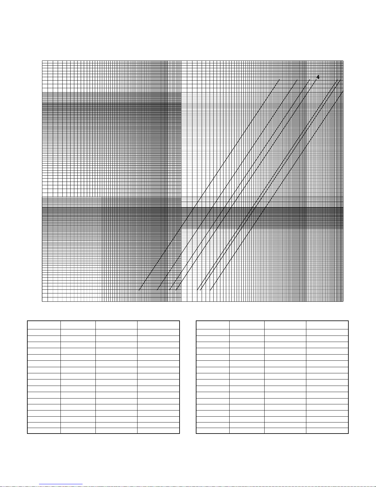
WATER SIDE PRESSURE DROP
200
PRESSURE DROP (FT. OF WATER)
1
3
2
4
5
6
7
234 8657910 603020 5040 70 1009080
1
10
20
604030 50 9070 80 100
200
300
400
500 600
700
FLOW RATE - GPM
MODEL No.
ASQ045B
ASQ050B
ASQ055B
ASQ060B
ASQ070B
ASQ080B
ASQ090B
ASQ100B
ASQ115B
ASQ130B
ASQ140B
ASQ150B
ASQ160B
ASQ170B
ASQ180B
ASQ190B
ASQ200B
CONVERSION FACTOR: GPM = 0.063 Liters per second.
NOTE: If an application requires certain water flow rate outside these limits, please check with your nearest dealer/sales office.
CURVE No. Maximum GPM
1
1
1
1
1
1
2
2
3
3
4
4
5
5
5
6
6
Minimum GPM
73
82
87
92
111
125
165
165
197
227
239
279
267
305
321
338
336
122
125
149
163
189
219
242
273
322
353
382
397
435
456
494
516
544
Feet of water = 2.989 Kilo Pascal (kpa).
MODEL No.
ASQ220B
ASQ230B
ASQ240B
ASQ250B
ASQ260B
ASQ270B
ASQ280B
ASQ300B
ASQ320B
ASQ330B
ASQ340B
ASQ350B
ASQ360B
ASQ380B
ASQ400B
ASQ420B
ASQ440B
CURVE No. Maximum GPM
3
3
3
3
4
4
4
5
5
5
5
5
5
6
6
7
7
Minimum GPM
377
388
406
430
439
470
504
526
567
584
566
594
640
657
686
773
827
800
900
1200
615
638
657
680
722
757
768
833
887
895
943
972
992
1070
1104
1167
1184
15001000
22
Page 23
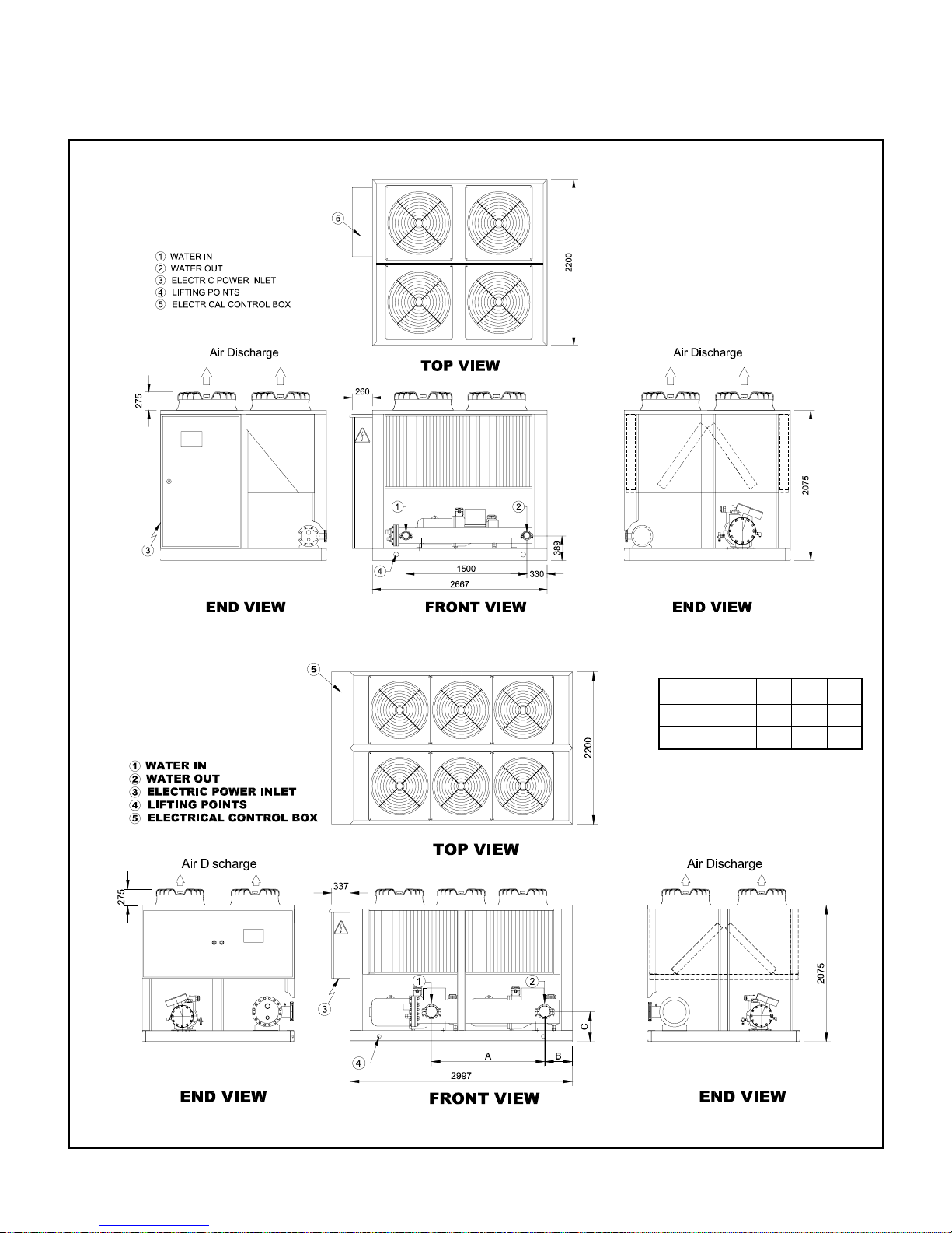
DIMENSIONS
ASQ045B, ASQ050B, ASQ055B, ASQ060B & ASQ070B
ASQ080B, ASQ090B & ASQ100B
DIMENSIONS
MODEL A B C
ASQ080B 1500 330 389
ASQ090B - ASQ100B 1730 360 414
NOTE: ALL DIMENSIONS ARE IN MILLIMETERS, UNLESS OTHERWISE SPECIFIED.
23
Page 24
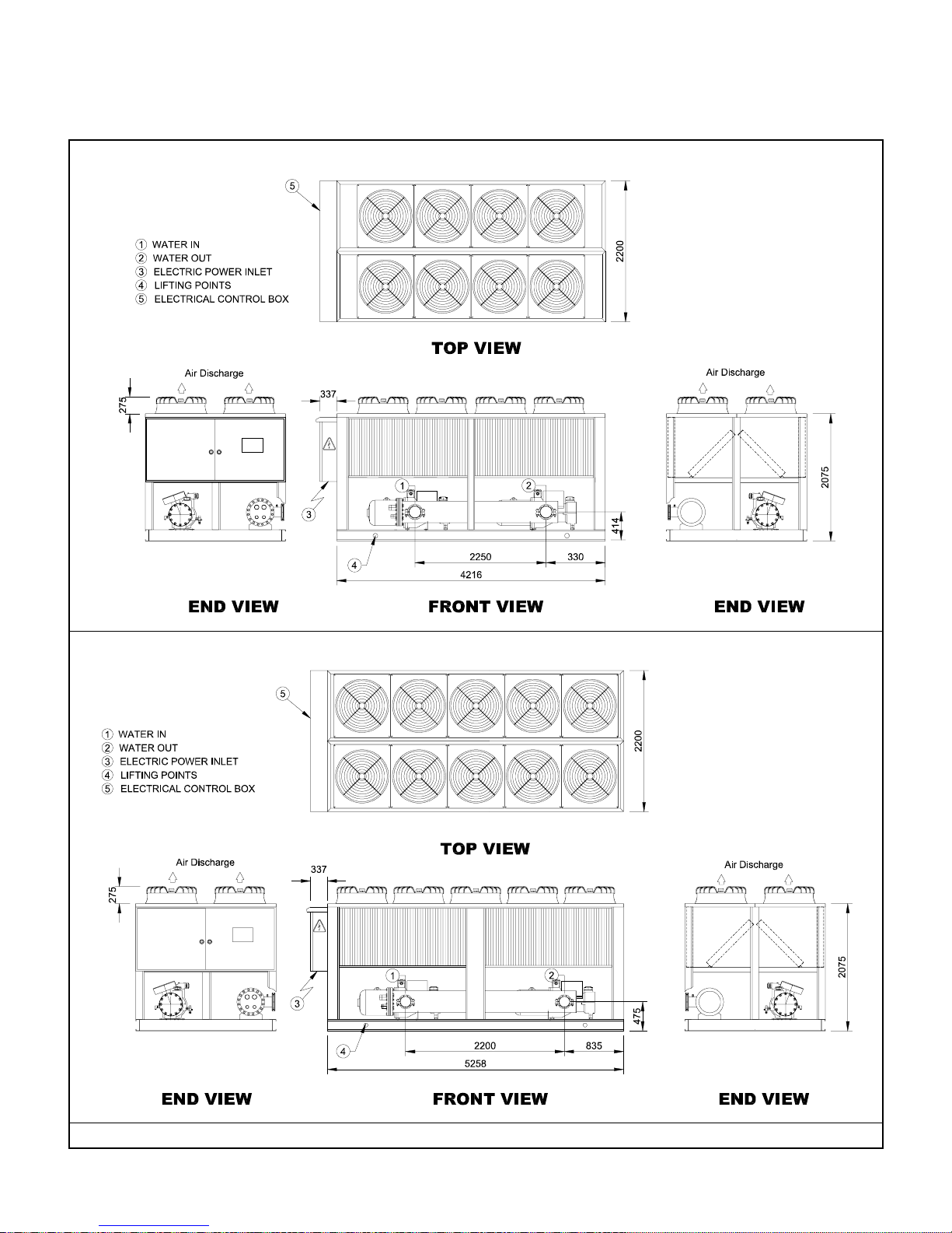
DIMENSIONS
ASQ115B & ASQ130B
ASQ140B & ASQ150B
NOTE: ALL DIMENSIONS ARE IN MILLIMETERS, UNLESS OTHERWISE SPECIFIED.
24
Page 25
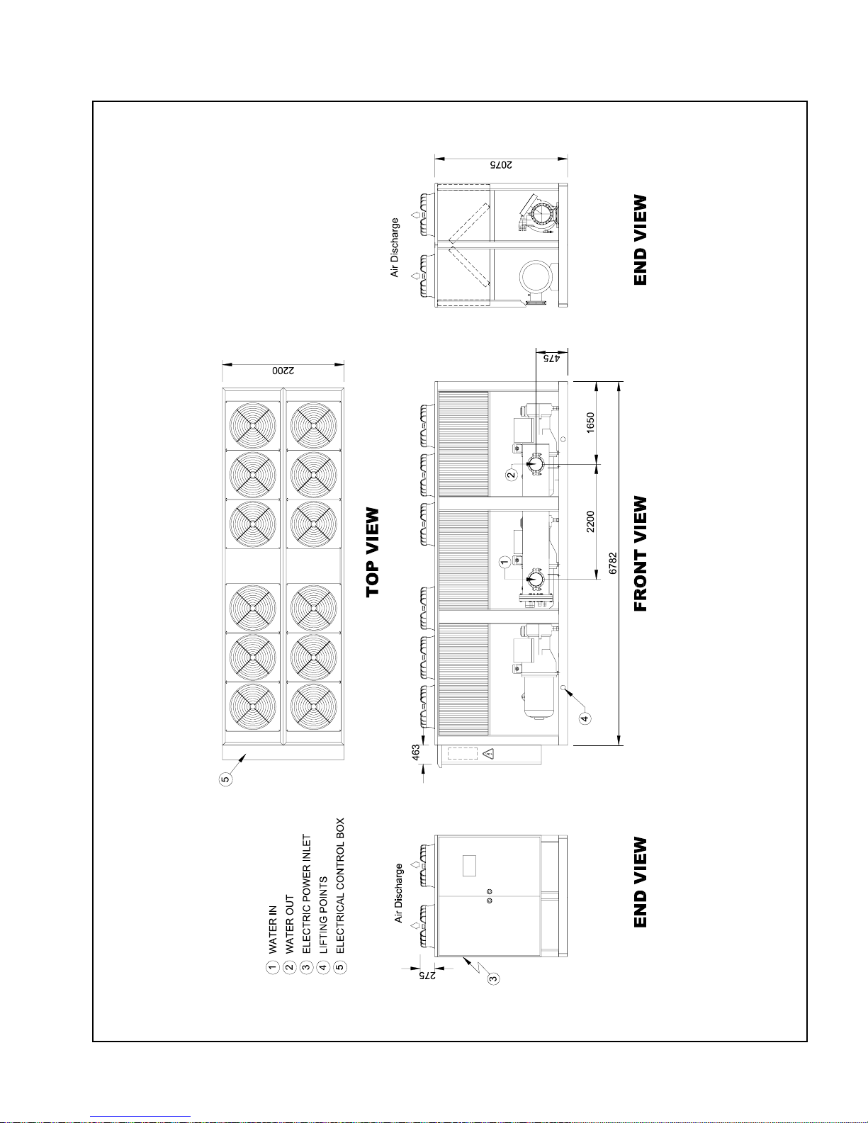
DIMENSIONS
ASQ160B, ASQ170B, ASQ180B, ASQ190B & ASQ200B
NOTE: ALL DIMENSIONS ARE IN MILLIMETERS, UNLESS OTHERWISE SPECIFIED.
25
Page 26
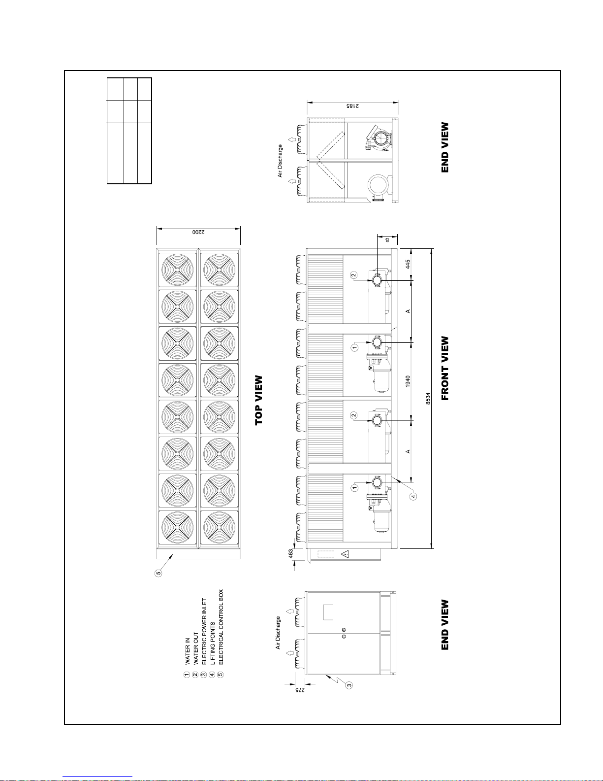
MODEL A B
ASQ220B - ASQ250B 2250 422
DIMENSIONS
ASQ260B - ASQ280B 2200 483
DIMENSIONS
ASQ220B, ASQ230B, ASQ240B, ASQ250B, ASQ260B, ASQ270B & ASQ280B
NOTE: ALL DIMENSIONS ARE IN MILLIMETERS, UNLESS OTHERWISE SPECIFIED.
26
Page 27
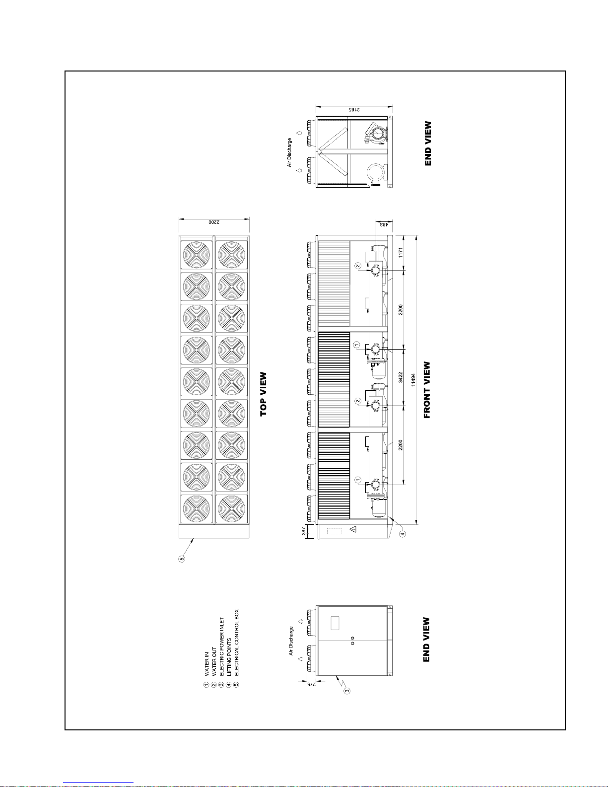
DIMENSIONS
ASQ300B, ASQ320B, ASQ330B & ASQ340B
NOTE: ALL DIMENSIONS ARE IN MILLIMETERS, UNLESS OTHERWISE SPECIFIED.
27
Page 28
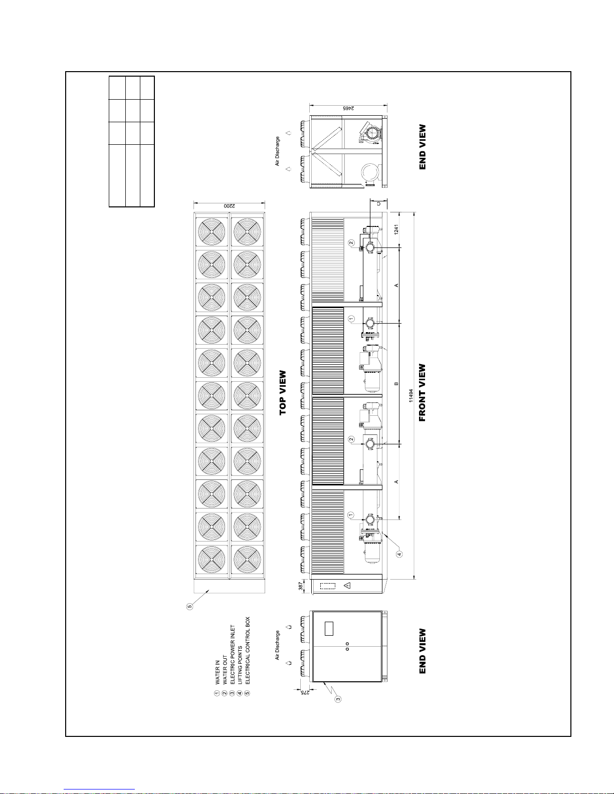
MODEL A B C
ASQ350B - ASQ400B 2200 3420 483
DIMENSIONS
ASQ420B - ASQ440B 2130 3490 510
DIMENSIONS
ASQ350B, ASQ360B, ASQ380B, ASQ400B, ASQ420B & ASQ440B
NOTE: ALL DIMENSIONS ARE IN MILLIMETERS, UNLESS OTHERWISE SPECIFIED.
28
Page 29
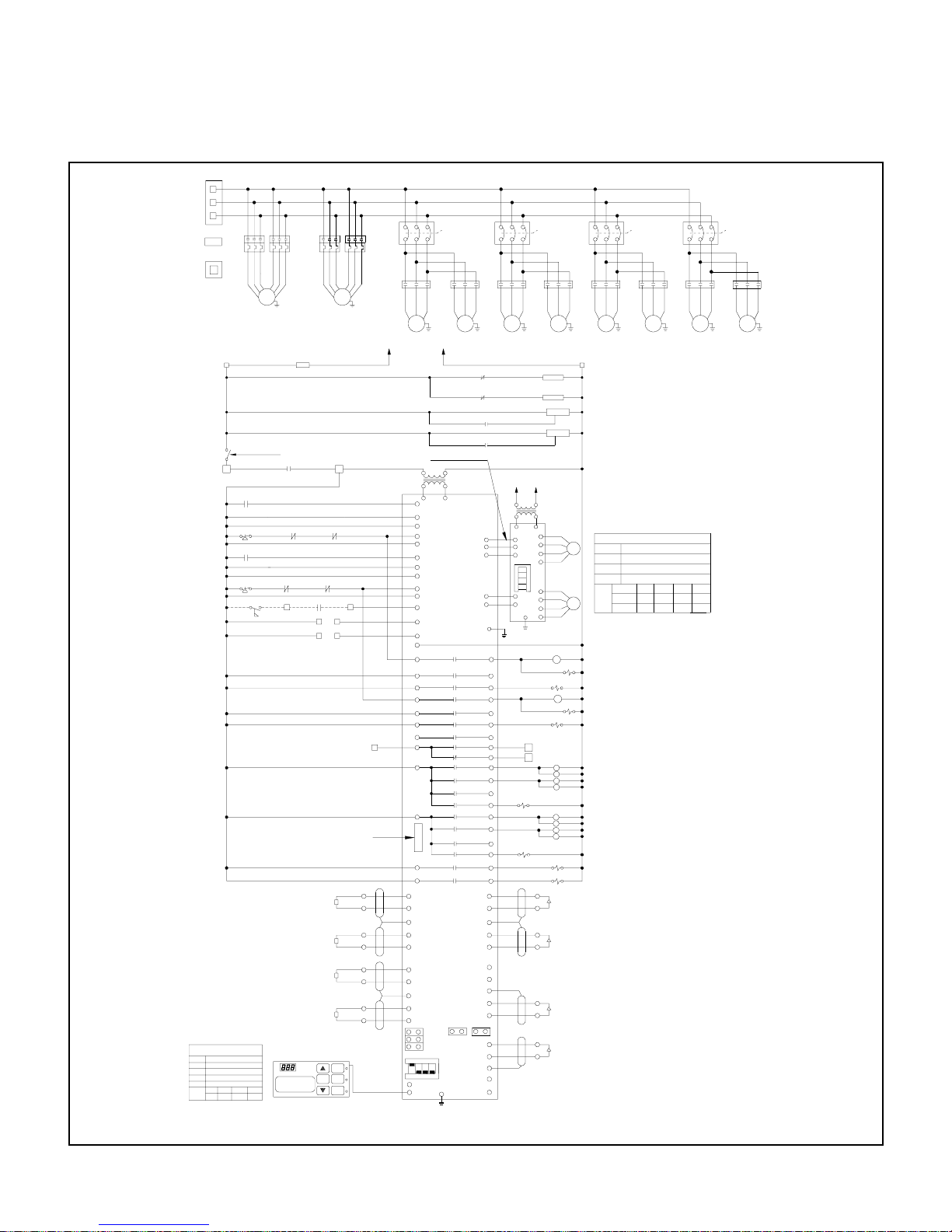
TYPICAL SCHEMATIC WIRING DIAGRAM
(PART WINDING START)
HVTB
L1
L2
L3
ETB/LUG
OLR1
NTB
N
1B
ATB
S1( CONTROL POWER)
1A
JUMPER & DIP SWITCH
SELECTION ON MAIN BOARD
JU1
CLOSED
JU2
CLOSED
TU1
CLOSED
CLOSED
TD1
OPEN
TL1
1
2
S1
(DIP)
ON
OFF34OFF
CC1
SSPS1
SSPS2
OFF
CC3
CC2
OLR3
OLR2
T3A
T1A
T2A
T2C
T3C
T1B
COMP
T1C
1
F1 5A
UVR
(SEE UVM CONNECTION)
8A
(See Circui t Breaker Option)
JP2
JP2A
OLR1-1
HPS1
HPS2
8B
JP3
JP3A
10B
FLS
11A
10A
(See Circui t Breaker Option)
OLR2-1
11B
10
OLR4-1
CWP*
1
1
REMOTE MONITORING
INTERFACE
(SEE OPTION BOX)
SUCTION TEMP SENSOR COMP1
T1S
TOUT/LWT TEMP. SENSOR
SUCTION TEMP SENSOR COMP2
TIN/RWT TEMP. SENSOR
USER INTERF ACE BOARD
SET
TOUT=10°C T IN=15°C
COOLING 75%
T2S
T3S
T4S
T2B
T3B
COMP
1
OLR3-1
2G
2H
On/Off
MENU
ESC
T2D
T1D
2
11
*
*
SERIAL CABLE
*
CC4
CB17
OLR4
T3D
FMC1
36C
37C
35C
FM
3
TO HVTB
L1
CONTROL VOLTAGE
230V-1PH
230VAC
24VAC
4
A1/D1(SSPS-1)
A2/D2(C B-1)
A3/D3(OL -1)
9A
A4/D4(H PS-1)
A5/D5(FC B-1)
A6/D6(SSPS-2)
A7/D7(C B-2)
22A
23A
24A
25A
22B
23B
26A
27A
A8/D8(OL -2)
A9/D9(HPS-2)
A10/D10(FCB-2)
A11/D11(FLW)
A12/D12 (EXT. ENABLE)
A13/D13 (EMERGENCY)
AC/DC(DIGITAL COM)
1C
2C
3C
4C
5C
6C
7C
8C
C
C
COM2
17C
18C
ST1
(A1-ST1)
SH
(A2-TOUT)
TOUT
ST2
(A3-ST2)
SH
TIN
(A4-TIN)
TU1
TD1
TL1
S1
ON
2134
X53
X52
GND
9B
7A
L1I
L2I
L3I
FMC2
35G
FM
TO NTB
N
SERIAL CABLE
TRANS
5
R1(DIG OUT)
R2(DIG OUT)
R3(DIG OUT)
R4(DIG OUT)
R5(DIG OUT)
R6(DIG OUT)
R7(DIG OUT)
R8(DIG OUT)
R9(DIG OUT)
R10(DIG OUT)
R11(DIG OUT)
R12(DIG OUT)
R13(DIG OUT)
R14(DIG OUT)
R15(DIG OUT)
R16(DIG OUT)
R17(DIG OUT)
R18(DIG OUT)
(A5-SP1)
(A6-DP1)
(A7-OP1)
(A8-SP2)
JU1
DIP
(A10-OP2)
36G
7
(A9-DP2)
CB18
37G
CCA3-1
CCA4-1
MB
EEV
AO1
A02
O1
SH
D1
O1
SH
S2
JU2
D2
O2
FMC3
CCA1-1
CCA2-1
-
+
-
+
PE
1O
2O
3O
4O
5O
6O
7O
8NO
8NC
9O
10O
11O
12O
13O
14O
15O
16O
17O
18O
-
+
-
+
-
+
-
+
-
+
SH
-
+
CB19
L1J
L2J
L3J
FMC4
36A
35A
37A
FM
1
3A
3B
TO ATB
230VAC
1
6
12/24VAC
X9
2A
V1
5A
+
DIP
S1
4
3
2
1
2B
V2
5B
+
PE
12A
14A
12B
14B
6A
16
18A
19A
SL.I1
20A
18B
19B
SL.I2
20B
15A
15B
28A
29A
30A
31A
28B
29B
30B
31B
7
1J
1K
A1
B1
A2
B2
T1
T1
+
+
-
+
+
-
UL3-1
UL3-2
35E
1HTR
2HTR
SSPS1
SSPS2
2
TRANS2
EEVB
X1 RED
X1
X1
X1
EEV CARD
X2
X2
X2
X2
CC1
CC2
UL4-2
GRN
WHT
BLK
RED
GRN
WHT
BLK
UL4-1
-
+
-
+
-
+
-
+
36E
FM
D1
D1
FMC5
36D
35D
37E
FM
5
4
2
ATB
COMP1 OILHTR
COMP2 OILHTR
T2
COMP1 SSPS
T2
COMP2 SSPS
EEVB JUMPER & DIP SWITCH
EEV
TD1
1
TU1
TL1
JU1
S1
(DIP)EEV
2
COMP1 CONTACTOR
LLS1
LIQUID LINE SOLENOID1
POWER DECREASE CP1
COMP2 CONTACTOR
LLS2
LIQUID LIN E SOLENOID2
POWER DECREASE CP2
HOT GAS BYPASS SOLENOID
ALARM - NO CONTACT
ALARM - NC CONTACT
FMC1
CTR-FAN 3
FMC2
CTR-FAN 7
FMC3
CTR-FAN 1
FMC4
CTR-FAN 5
LIQUID INJECTION 1
FMC5
CTR-FAN 4
FMC6
CTR-FAN 8
FMC7
CTR-FAN 2
FMC8
CTR-FAN 6
LIQUID INJECTION 2
POWER INCREASE CP1
POWER INCREASE CP2
SPT1 - COMP1
SUCTION PRESSURE
TRANSDUCER
DPT1 - COMP1
DISCHARGE PRESSURE
TRANSDUCER
SPT2 - COMP2
SUCTION PRESSURE
TRANSDUCER
DPT2 - COMP2
DISCHARGE PRESSURE
TRANSDUCER
37D
ALCO
EX8
EX7
L1K
L2K
L3K
FMC6
CB20
FMC7
37H
36H
35H
FM FM
8
CLOSED
CLOSED
OPEN
OPEN
1
2
ON
OFF
ON
OFF
L1L
L2L
L3L
FMC8
36F
35F
36B
35B
37B
2
3
4
ON
OFF
ON
OFF
37F
FM
6
NOTE: 1. Refer to next page for legend, notes & wiring diagram for optional items.
2. Refer to unit control box (inside panel) for exact wiring diagram.
29
Page 30

Page 31
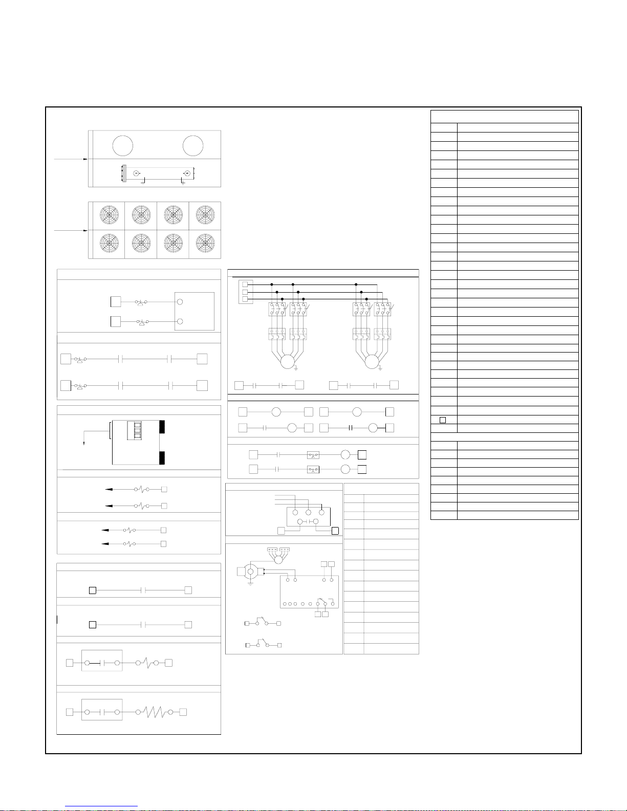
TYPICAL SCHEMATIC WIRING DIAGRAM
COMP LAYOUT
CONTROL PANEL
CONTROL PANEL
LPS CONNECTION WITH OUT CB (OPTIONAL)
REMOVE JP2
REMOVE JP3
LPS CONNECTION WITH CB (OPTIONAL)
LPS1
1
LPS2
1
REMOTE MONITORING CONNECTION (OPTIONAL)
TO
GATEWAY
ECONOMIZER CONNECTION (OPTIONAL)
TO MB (20)
TO MB (50)
EQUALIZER CONNECTION (OPTIONAL)
TO CCA1-1
TO CCA2-1
UNIT EXTERNAL ENABLE/DISABLE OPTION
UNIT EMERGENCY OPTION
HOT GAS BYPASS OPTION
7C
1
IF THE HGBS IS ENABLE COOLER HEAT ER TAPE IS NOT POSSIBLE
COOLER HEATER TAPE OPTION
7C R71
COMP1
FAN LAYOUT
COMP FAN 1
FAN1
FAN2
FAN3 FAN5
FAN4 FAN6
COMP FAN 2
MAIN BOARD
LPS1
LPS2
22A
63A
63B
CB3A-1
63A
1
1
CB1A-1
REMOVE JP2
63B
CB2A-1
22B
CB4A-1
REMOVE JP3
GND
+
IS485
ECO1
13A
ECO2
13B
SL.E1
3A
SL.E2
3B
1
1
MB
R7
7O
MB
7O
VFC FROM CUSTOMER PANEL
VFC
VFC FROM CUSTOMER PANEL
VFC
HGBS
15
HEATER
15
ATB
ATB
COMP2
A2/D2
A7/D7
D2(MB)
D7(MB)
TO MAIN
BOARD (COM2)
ECONOMIZER 1
2
2
ECONOMIZER 2
EQUALIZER 1
2
EQUALIZER 2
2
ATB
2G
ATB
2H
2
2
FAN7
FAN8
23A
23B
(PART WINDING START)
COMPRESSOR PART WIND WITH CIRCUIT BREAKER OPTION
L1
L2
L3
HVTB
CB1
L1A
L2A
CC1
OLR1
T2A
T1A
CBA1-1
CBA3-1
22A
1
COMPRESSOR CONTACTOR CONNECTION FOR PART WIND START
12A
FOR PART WIND START TIME DELAY SWITCH (TDS) OPTION
CC1
CC1A-2
1
61A
CC1A-2
1
CC2A-2
1
L3A
T3A
COMP
CB3
L2C
L3C
L1CT1C
CC3
OLR3
T3C
T2C
1
23A
D2 (MB)
CC3
221
TDS1-1SEC
61A
TDS2-1SEC
61B
UVM CONNECTION
L1
L2
NOTE:
TERMINAL A,B,& C
ON UVM TO BE
PHASE MATCHED WITH
UNIT CONTROLS.
L3
UVR
1A
GROUND FAULT PROTECTION OPTION.(GFP)
COMP
70A/B
71A/B
T2
TI
31
313232
A3/D3 (MB)
65A
REMOVE JP2A
A8/D8 (MB)
65A
REMOVE JP3A
EARTH FAULT RELAY
Current Transformer
wire number, 70A/71A for
Comp 1 and 70B/71B for
Comp 2.
1
Comp 1
Comp 2
EFR1
1
EFR2
1
12B
62A
62B
UVM
1
12
A1 A2
32 31 34
CB2
L1B
L2B
L3B
CC2
OLR2
T3B
T2B
T1B
COMP
CBA4-1
CBA2-1
22B
CC2
CC2A-2
CC4
61B
CC3
2
CC4
2
JUMPER SE TUP ON
MAIN BOARD
TL2
TD2
JU11
JU13
JU15
JU5
JU6
JU7
JU8
JU9
JU4
JU3 1-2 CLOSED
JU19
JU12
JU10
L2D
L1D
T2D
T1D
2
OPEN
CLOSED
CLOSEDTU2
1-2 CLOSED
1-2 CLOSED
1-2 CLOSED
1-2 CLOSED
1-2 CLOSED
1-2 CLOSED
1-2 CLOSED
1-2 CLOSED
1-2 CLOSED
1-2 CLOSED
1-2 CLOSED
1-2 CLOSED
L3D
T3D
LEGEND
CBA
THERMAL MAGNETIC CIRCUIT BREAKER AUXILIARY
COMP COMPRESSOR
CC COMPRESSOR CONTACTOR
CCA COMPRESSOR CONTACTOR AUXILIARY
CWP CHILLED WATER PUMP
ETB EARTH TERMINAL BLOCK
FLS FLOW SWITCH
FM FAN MOTOR
FMC FAN MOTOR CONTACTOR
FT
THERMAL MAGNETIC CB FAULT TRIP CONTACT
F FUSE
HPS HIGH PRESSURE SWITCH
HGBS HOT GAS BYPASS SOLENOID
HVTB HIGH VOLTAGE TERMINAL BLOCK
JP JUMPER
LPS LOW PRESSURE SWITCH
MB MASTER BOARD
NTB
NEUTRAL TERMINAL BLOCK
OLR OVER LOAD RELAY
PT PRESSURE TRANSDUCER
CB4
P POTENTIAL BAND
SLE ECONOMIZER SOLENOID
CC4
OLR4
SB SLAVE BOARD
S1 CONTROL SWITCH
SSPS SOLID STATE PROTECTION SYSTEM
TMCB
THERMAL MAGNETIC CIRCUIT BREAKER
TRANS TRANSFORMER
TDS TIME DELAY SWITCH
D7 (MB)23B
TS TEMPERATURE SENSOR
UL UNLOADER
UVM UNDER VOLTAGE MONITOR
2
2
UVR UNDER VOLTAGE RELAY
TERMINAL BLOCK
- - - - - FIELD WIRING
LEGEND ON MAIN BOARD
D1 DIGITAL INPUT 1
C/1C COMMON
1O DIGITAL OUT 1
DC DIGITAL COMMON
T1 THERMISTOR 1
SH SHIELD
X52/X53 SERIAL COMMUNICATION PORT
PE POTENTIAL EARTH
JU/TU/TD/TL
BOARD JUMPERS
NOTES
1. POWER SUPPLY,
ALL FIELD WIRING TO COMPLY WITH LOCAL CODES.
2. FUSES TO DUAL ELEMENT TYPE.
3. USE COPPER CONDUCTORS ONLY.
4. FUSED DISCONNECT SWITCH OR CIRCUIT
BREAKER TO BE PROVIDED BY END USER WITH
RATING AS RECOMMENDED BY MANUFACTURER.
5. POWER MUST BE SUPPLIED TO CRANKCASE
HEATER FOR MINIMUM OF 12 HOURS PRIOR TO
SYSTEM START UP.
IF POWER IS OFF 6 HOURS OR MORE, CRANKCASE
HEATER MUST BE ON FOR 12 HOURS BEFORE
OPERATING THE SYSTEM.
FAILURE TO FOLLOW THESE INSTRUCTIONS MAY
RESULT IN COMPRESSOR DAMAGE.
6. MARK IN THE BOX FOUND AT THE UPPER RIGHT OF
THE RESPECTIVE OPTIONAL ITEM, IF THE OPTIONAL
ITEM IS INCLUDED IN THE UNIT.
380/415V-3Ph-50Hz
.
IF THE COLLER HEATER TAPE IS EN ABLE HGBS IS NOT POSSIBLE
30
Page 32

MICROPROCESSOR CONTROLLER
Sequence of Operation
The following describes the sequence of operation for a two screw compressor chiller unit.
Operation is similar for a one or four compressor unit.
For initial start-up, the following conditions must be met:
All power supplied to the unit shall be energized for 12 hours.
·
Control power switch on for at least 5 minutes.
·
All safety conditions satisfied.
·
Press ESC on the microcomputer keypad.
·
Chilled water pump running and chilled water flow switch contact closed.
·
Customer interlock contact closed, if any.
·
STAGE - ON SEQUENCE
Staging ON & OFF sequence, shall be accomplished by the Leaving water temperature control selection.
Stage #1:
If the Leaving Water Temperature is greater than the Stage 1- ON water temperature set point value, the Compressor #1
liquid line solenoid & slider control valves shall be switched ON. Now the compressor is in the minimum or unloaded
capacity. The compressor capacity is varied to achieve the full/part load capacity as per the load demand.
As discharge pressure of Compressor #1 rises, the corresponding fans are energize accordingly to the fan stage-ON set
point. If the discharge pressure falls below the fan stage-OFF set point value, the corresponding fans will turn off.
Stage #2:
If the Leaving Water Temperature is greater than the Stage 2- ON water temperature set point value, the Compressor #2
liquid line solenoid & slider control valves shall be switched ON. Now the compressor is in the minimum or unloaded
capacity. The compressor capacity is varied to achieve the full/part load capacity as per the load demand.
As discharge pressure of Compressor #2 rises, the corresponding fans are energize accordingly to the fan stage-ON set
point. If the discharge pressure falls below the fan stage-OFF set point value, the corresponding fans will turn off.
STAGE - OFF SEQUENCE
During the staging OFF, the first-in last-out sequence is adopted, if equalization of compressor timing is not selected.
Else the more used is switched off.
As the applied load decreases and when the leaving water temperature falls below the stage 2 -OFF water temperature
set point value, stage 2 is turned off.
If the leaving water temperature falls below the stage 1-OFF water temperature set point value, the stage 1 is turned off.
31
Page 33

TROUBLESHOOTING GUIDE
1) No LED display lit or erratic display behavior
a) Check serial cable integrity.
b) Check serial cable connections on both the User Interface Board and the Main Board.
c) Check correct and tight insertion of jumpers JU1 and JU2 on the Main Board.
d) Check correct and tight insertion of jumpers TU1 and TD1 on the User Interface Board and on the last board of the
network.
2) Controller does not respond to keypad
a) Check serial cable integrity.
b) Check serial cable connections on both the User Interface Board and the Main Board.
c) Check correct and tight insertion of jumpers TU1 and TD1 on the User Interface Board, main and/or auxiliary
board.
d) Check dip switches and integrity on the User Interface Board.
3) Several analog values reading incorrectly
a) Check correct and tight connection of the probes to the board.
b) Check the probe cable: test for short-circuit.
c) The pressure transducer probe is a 4-20mA transmitter check the polarity of the connection on the Board.
d) Check if the power supply voltage is into the specified limits: 24Vac +/- 10%.
e) The temperature probe is a PTC sensor disconnect it from the board and measure its resistance that is 1000 ohm
0
C or 1200 ohm at 500C.
at 25
4) Digital input reading incorrectly
a) Check if the auxiliary 220 Vac voltage is present in the electrical box.
b) Check if the AC input on the Board is correctly connected to one of the 220 Vac terminals in the electrical box.
c) Check if A1/A14 inputs are correctly connected with respect to the cabling diagram of the electrical box.
5) No LCD display lit or erratic display behavior
a) Check serial cable integrity.
b) Check serial cable connections on both the User Interface Board and the Main Board.
c) Check correct and tight insertion of jumpers JU1 and JU2 on the Main Board.
d) Check correct and tight insertion of jumpers TU1 and TD1 on the User Interface Board, main and/or auxiliary
board.
e) Adjust display intensity by rotating trimmer RV1 counter-clockwise (from the back side of the board).
6) No LED H1 blinking light on NG3 Board
a) Check power supply cable an connection.
b) Check if the power supply voltage is into the specified limits: 24Vac +/- 10%.
c) Check for fuse F1, replace with 1AT/250V if blown.
7) No display of leds on User Interface Board
a) Check serial cable integrity.
b) Check serial cable connections on both the User Interface Board and the Main Board.
c) Check correct and tight insertion of jumpers JU1 and JU2 on the Main Board.
d) Check correct and tight insertion of jumpers TU1 and TD1 on the User Interface Board, main and/or auxiliary
board.
32
Page 34

8) Auxilliary board not responding to commands
a) Check if LED H1 on Auxilliary board is blinking , if not go to point (6).
b) Check serial cable integrity.
c) Check serial cable connections on both the Main and the Auxilliary boards.
d) Check that jumpers JU1 and JU2 on the Auxilliary boards are not installed.
e) Check correct and tight insertion of jumpers TU1 and TD1 on the User Interface Board, main and/or auxiliary
board.
9) Analog Outputs not responding
a) Check Analog Output cables integrity (for short-circuit).
b) Check Analog Output cabling and connections.
c) Check if the power supply voltage is into the specified limits: 24VAC +/- 10%.
d) Check the fuse F1, replace with 1AT/250V if blown.
10) Digital Outputs not responding
a) Check Digital Output cables integrity (no short-circuit, no open-circuit).
b) Check digits Output cabling and connections.
c) Check if the power supply voltage is into the specified limits: 24VAC +/- 10%.
d) Check the fuse F1, replace with 1AT/250V if blown.
11) Serial Communication with Remote Monitoring Control not Functioning
a) Check the serial cable connected on plug-in board IS-485 mounted on the Main Board.
b) Check if the plug-in board is correctly mounted on the Main Board.
c) Check if jumpers X5 and X6 on the plug-in board IS-485 are correctly installed.
d) Check if jumpers X17 and X18 on the GATEWAY board are correctly installed.
33
Page 35

APPLICATION GUIDELINES
INTRODUCTION
These guidelines should be considered when designing systems and their installation utilizing COOLINE ASQ series
liquid chillers. Stable operation, performance and reliability of units is often dependent upon proper compliance with
these recommendations. When any application varies from these guidelines, it should be referred with Cooline Air Conditioners for specific recommendations.
UNIT SELECTION/SIZING
Unit selection procedure and capacities are provided in this catalog for proper selection. The COOLINE electronic selection program may also be utilized for this purpose.
Over sizing chillers beyond a maximum limit of 5 – 10 % in order to assure adequate capacity or considering future
expansions is not recommended. Over sizing adversely affects the operating efficiency due to erratic system operation
and excessive compressor cycling which also results in reduced compressor life. It should be noted that, units operate
more efficiently when fully loaded rather than larger equipment operating at partial capacities. In addition, an oversized
unit is usually more costly to purchase, install and operate.
When over sizing is desired due to anticipation of future plant expansion, consider using multiple units. For example,
install a single chiller for the present load requirement and install a second chiller for the foreseen additional load demand
due to expansion. Further, it is also recommended that installing two chillers instead of a single chiller be considered in
applications where partial load operation at low capacities is necessary.
Operation of two chillers at higher loading is preferred to operating a single chiller at or near its minimum possible capacity.
FOULING FACTOR AND WATER REQUIREMENT
The tabulated performance data provided in this catalog are based on a fouling factor of 0.00010 hr-ft2-0F/Btu (0.000018
m2-0C/W). As fouling factor is increased, unit capacity decreases and power input increases. For unit selection at other
fouling factors, apply appropriate correction factor from the table provided in this catalog.
These chillers are suitable for operation with well maintained water systems. Using unclean and untreated water may
result in scale and deposit formation causing reduced cooler efficiency or heat transfer and corrosion or pitting leading to
possible equipment damage. The more scale forming material and suspended solids in the system water, the greater the
chances of scale and deposit formation and fouling. These include calcium, magnesium, biological growth (algae, fungi
and bacteria), dirt, silt, clays, organic contaminants (oils), silica, etc. which should be kept to the minimum to retard scale
and deposit formation. In order to prevent corrosion and pitting, the pH value of the water flowing through the cooler must
be kept between 7 and 8.5. COOLINE recommends that a water treatment specialist is consulted to provide and maintain
water treatment, this is particularly critical with glycol systems.
EFFECT OF ALTITUDE ON UNIT CAPACITY
The tabulated performance data provided in this catalog are for use at or near sea level altitude application.
substantially above sea level, the decreased air density will reduce condenser capacity and therefore unit capacity. For unit
selection at these higher altitudes, apply appropriate correction factor from the table provided in this catalog.
At altitudes
HIGH AMBIENT CONSIDERATION
These chillers are designed for year round operation over a range of ambient temperatures. As a standard, these chillers
can start and operate satisfactorily up to 1250F (520C) ambient temperature at rated nominal voltage.
WATER FLOW RATES AND COOLER PRESSURE DROP
The maximum and minimum water flow rates for all unit models and the pressure drop chart are provided in this catalog.
The design water flow rate must be within this range. Design flow rates below the minimum limits will result in laminar
flow causing freeze-up problems, stratification and poor control and flow rates beyond the maximum limits cause excessive pressure drop and severe tube erosion.
During unit operation, water flow rate must not vary more than ± 5% from the design flow rate. The water flow switch should be
calibrated accordingly. The piping and pumping layout should be right for the application and must assure proper water return
and circulation. When using glycol solution, flow rate and pressure drop are higher than with water, therefore care must be
taken not to exceed the limits. In such applications, consult Cooline Air Conditioners for specific recommendations.
34
Page 36
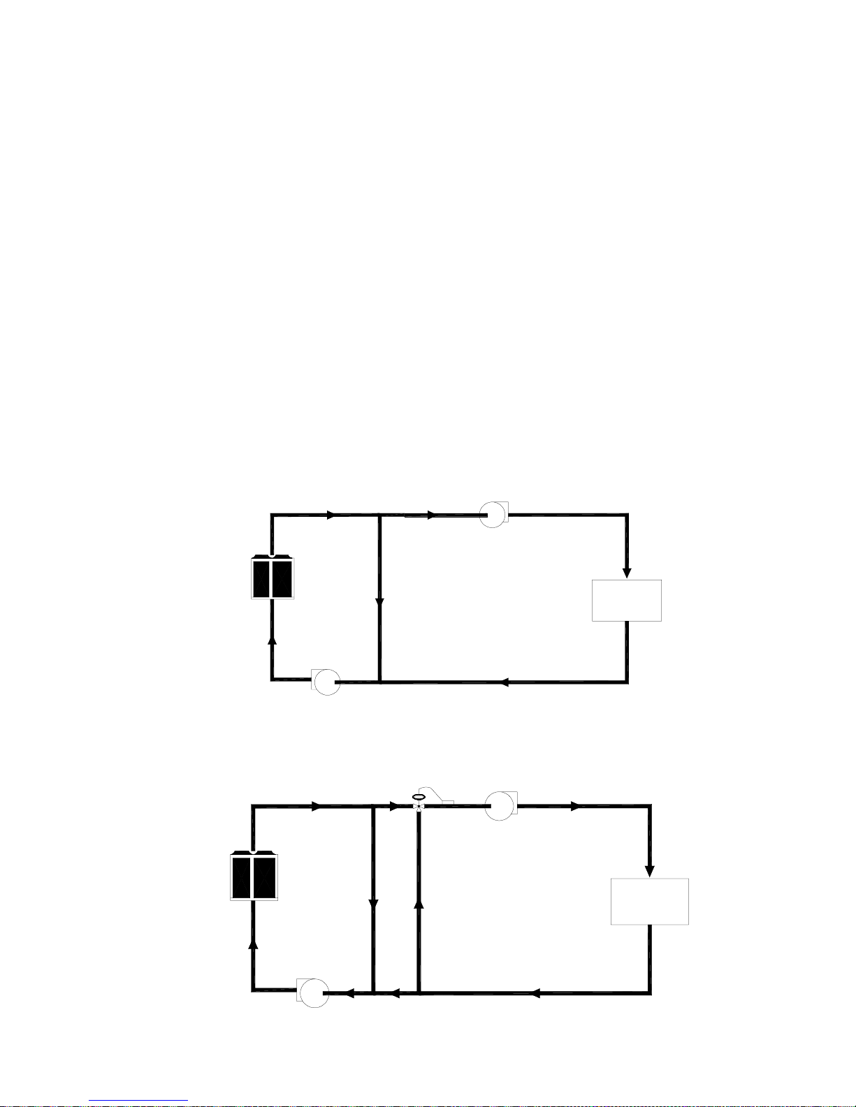
COOLER FLUID (WATER OR GLYCOL) TEMPERATURES RANGE
Unit can start and pull down from 950F (350C) entering fluid temperature. The design leaving chilled fluid temperature
(LCWT) range as mentioned earlier in the tabulated performance data is 40 to 500F. The design entering chilled fluid
temperature range is 50 to 600F. The design cooler temperature drop (∆T) range is 5 to 150F.
The tabulated performance data provided in this catalog is based on a chilled water temperature drop of 100F. Units may
be operated at any desired temperature drop within the range of 5 to 150F as long as the temperature and flow limits are
not violated and appropriate correction factors are applied on the capacity and power input. The COOLINE electronic
selection program can be very handy in selecting equipment at different temperature drops.
It should be noted that temperature drop outside the aforesaid range is not permitted as it is beyond the optimum range of
control and could adversely affect the functioning of microprocessor controller and may also prove to be detrimental for the
equipment.
FLOW RATES AND/OR WATER TEMPERATURES OUT OF RANGE
Certain applications (particularly process cooling jobs) call for flow rates and/or water temperatures that are outside the
above mentioned limits/range. Our chillers can be utilized for these applications by selecting the chiller based on the
specific process load and making a suitable piping and mixing arrangement in order to bring the flow rates and/or water
temperatures relevant to the chiller within acceptable limits.
Example 1:
An application requires 240 GPM of water at 450F and the return water temperature is 650F.
A standard chiller can be used for this application as shown in the following basic schematic layout (single mixing arrangement).
45°F
500 GPM
45°F
240 GPM
200 TR
Chiller
45°F
260 GPM
54.6°F
500 GPM
65°F
240 GPM
Load
200 TR
Example 2:
An application requires 192 GPM of water at 650F and the return water temperature is 800F.
A standard chiller can be used for this application as shown in the following basic schematic layout (dual mixing arrangement).
45°F
340 GPM
45°F
82.2 GPM
65°F
192 GPM
120 TR
Chiller
340 GPM
53.4°F
45°F
257.8 GPM
80°F
109.8 GPM
Load
120 TR
53.4°F
340 GPM
80°F
82.2 GPM
35
80°F
192 GPM
Page 37

COOLER FREEZE PROTECTION
If the unit is located in an area where ambient temperatures fall below 320F (00C), cooler protection in the form of Ethylene
Glycol Solution is required to protect the cooler and fluid piping from low ambient freeze-up. This glycol solution must be
0
added to the water system loop to bring down the freezing point of water to a difference of 15
F (8.30C) below minimum
operating ambient temperature.
Using this glycol solution causes a variation in unit performance, flow rate and pressure drop, therefore appropriate
correction factors from the aforementioned table in this catalog should be applied.
MULTIPLE CHILLER ARRANGEMENT OR PLANT CONFIGURATION
A multiple chiller system has two or more chillers connected by parallel or series piping to a common distribution system.
Multiple chiller arrangements offer the advantage of operational flexibility, standby capacity and less disruptive maintenance. Also, they offer some standby capacity if repair work must be done on a chiller from a set of duty chillers. Starting
in-rush current is reduced, as well as power costs at partial-load conditions.
A multiple chiller arrangement should be provided if the system load is greater than a single chiller capacity, standby
0
capability is desired, large temperature drop (greater than 15
F) is desired or application calls for splitting the total
capacity for better part load operation.
In designing a multiple chiller plant, units of same size should be preferred over different sizes to facilitate balanced water
flow. It is mandatory that cooler flow rates must be balanced to ensure proper flow to each chiller based on its respective
capacity. As mentioned above, two basic multiple chiller systems are used: parallel and series chilled water flow.
In the parallel arrangement, liquid to be chilled is divided among the liquid chillers; the multiple chilled streams are
combined again in a common line after chilling. Water temperatures (EWT or LWT) can be used to cycle units On and Off
based on the cooling demand. Parallel arrangements permit adding chillers in the future for plant expansion with the
appropriate considerations beforehand.
In the series arrangement, the chilled liquid pressure drop may be higher unless coolers with fewer liquid-side passes or
baffles are used. No over chilling by either unit is required, and compressor power consumption is lower than it is for the
parallel arrangement at partial loads. It is also possible to achieve higher overall entering to leaving temperature drops,
which may in turn provide the opportunity for lower chilled water design temperature, lower design flow and resulting
installation and operational cost savings. Series chiller arrangements can be controlled in several ways based on the
water temperatures depending on cooling demand.
A valved piping bypass is suggested around each chiller to facilitate future servicing as it gives the personnel an option
for service without a complete shutdown.
0
COOLINE recommends the parallel arrangement for design temperature drops (∆T) up to 15
0
ment beyond that i.e., 16 to 20
F. Complete design details on these parallel and series chilled water flow arrangements
F and the series arrange-
can be found in the ASHRAE handbooks and other design literature which should be referred by the designer in preparing
his detailed designs.
PIPING ARRANGEMENTS AND PLANT LAYOUT
Our chillers are suitable for incorporating in ‘Two Pipe’ single temperature systems or ‘Four Pipe’ independent load
systems. The system piping circuit (load distribution circuit) should be basically parallel piping either Direct Return or
Reverse Return system with a good pumping arrangement.
The method of circuiting and pumping is a judgment decision by the designer. The designer must weigh the pros and
cons of cost, nature of load and configuration of building, energy economics, flexibility, installation requirements and
others to determine the best arrangement for his project. In all cases, it must be ensured that the design water flow is
constantly maintained through the chillers at all stages of operation. Some suggested arrangements with basic schematic layouts are as follows:
36
Page 38
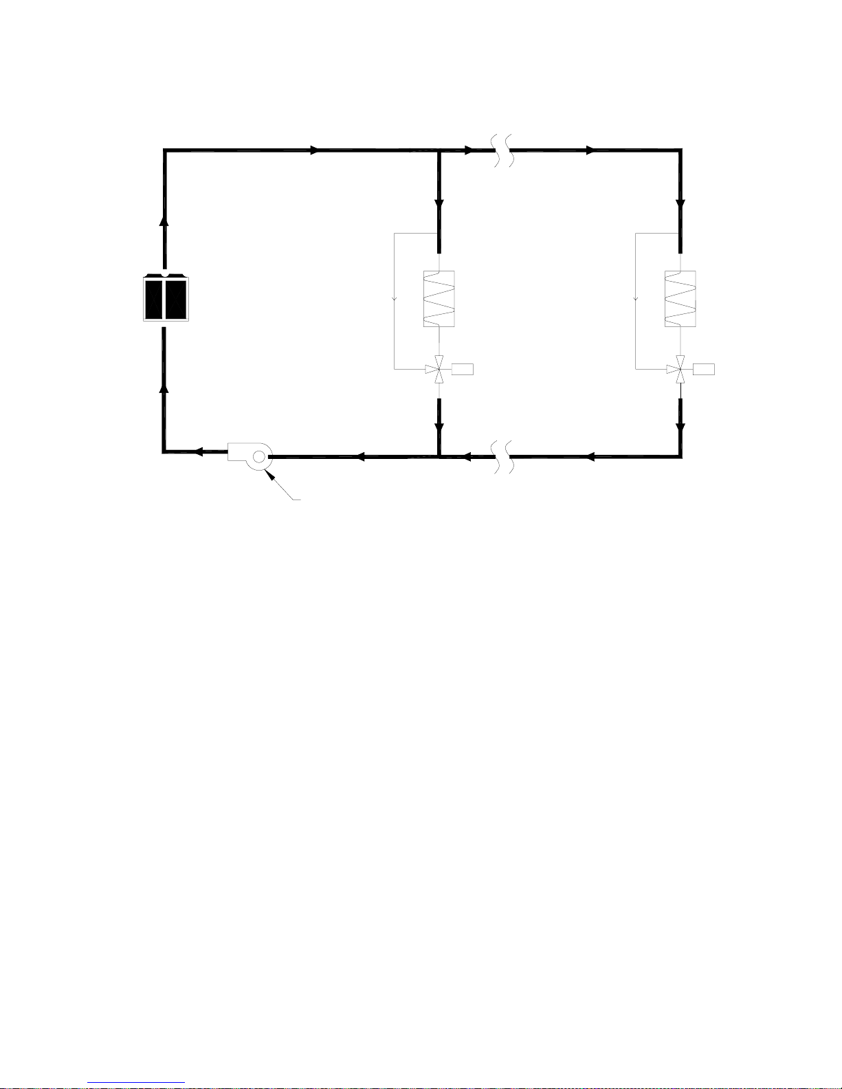
A. Single or multiple chillers with constant water flow through chillers and load system:
CHWS
Chiller
Load Load
3-Way
Valve
3-Way
Valve
CHWR
Constant Speed Pump
In this type of arrangement, constant water flow through the chillers and load distribution piping circuit is maintained.
Before proceeding further, a brief explanation on the operation of a typical chilled water system / valves which is fundamental to the design or analysis of a system.
Where multiple zones of control are required, the various load devices are controlled first; then the source (chillers)
system capacity is controlled to follow the capacity requirement of the loads. Control valves are commonly used to control
loads. These valves control the capacity of each load by varying the amount of water flow through the load device.
Control valves for these applications are two-way (straight-through) and three-way valves. The effect of either valve is to
vary the amount of water flowing through the load device. With a two-way valve, as the valve strokes from full-open to fullclosed, the quantity of water flowing through the load gradually decreases from design flow to no flow. The three-way
mixing valve has the same effect on the load as the two way valve - as the load reduces, the quantity of water flowing
through the load decreases in proportion to the load and the difference amount is directed through a bypass.
In terms of load control, a two-way valve and a three-way valve perform identical functions—they both vary the flow
through the load as the load changes. The fundamental difference between the two-way valve and the three-way valve is
that as the source or distribution system sees the load, the two-way valve provides a variable flow load response and the
three-way valve provides a constant flow load response.
Referring to the foregoing schematic layout, this is a conventional system and is not as energy efficient as the two-way
valve systems especially on the pumping side due to constant water circulation in the system. On multiple chiller installations, pumps are required to operate continuously and the sequencing of chillers is dependent on water temperatures.
37
Page 39
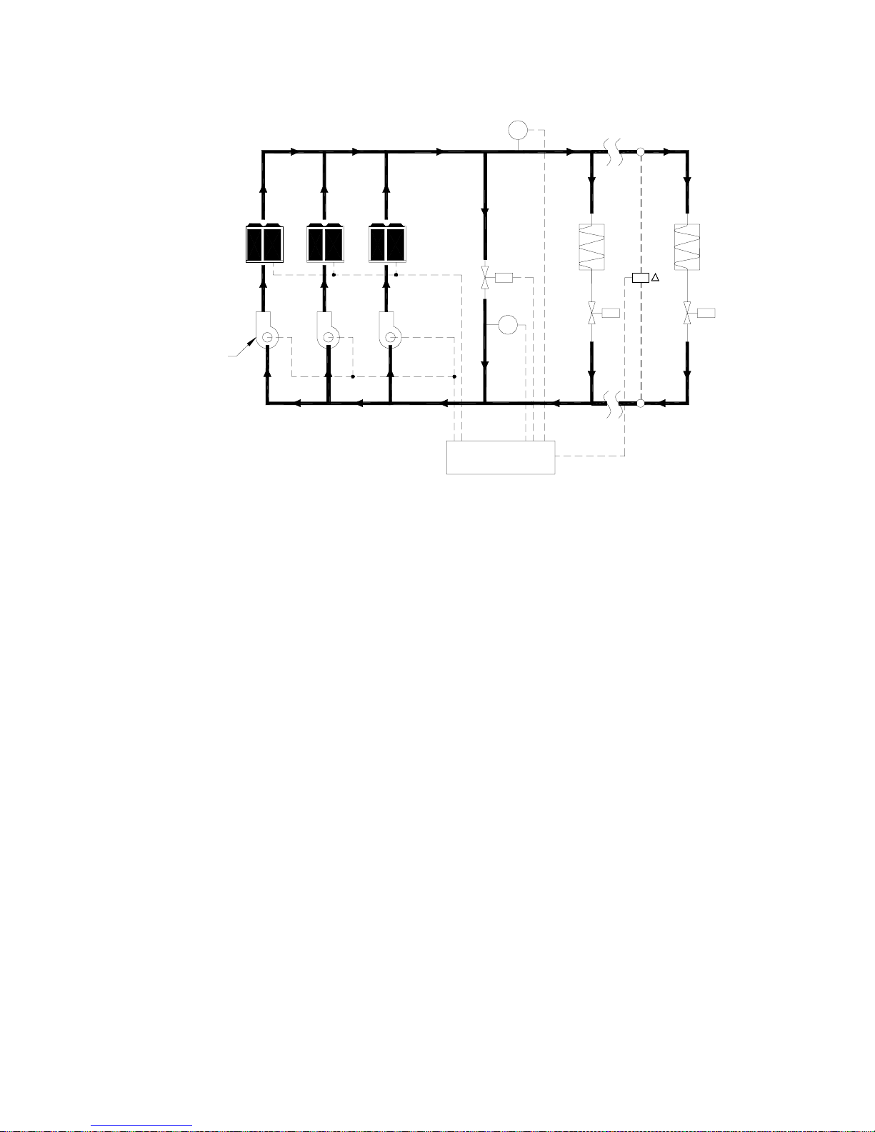
B. Single or multiple chillers with constant water flow through chillers and variable water flow through load system:
FM-1
CHWS
Bypass
Line
Variable Speed Pump
Chiller
Bypass
Control
Valve
FM-2
System
Controller
CHWR
Load
2-Way
Valve
P
Load
2-Way
Valve
In this type of arrangement, constant water flow through the chillers is maintained, however the quantity of water flowing
through the load distribution piping system decreases in proportion to the load and the difference amount is directed
through a bypass pipe that connects the supply and return headers. Brief sequence of operation is as follows:
The bypass with its control valve and flow meter provides the design flow required through the chillers. Flow meter FM1
measures the actual flow to the chilled water system. The system flow is compared with the required flow for the chillers.
The difference is made up through the bypass and is monitored by flow meter FM2. This flow meter controls the bypass
valve to maintain the desired flow in the bypass based on the set points in the system controller (the valve is positioned
by sum of flow meters FM1 and FM2).
The speed of the chiller pumps is controlled by the differential pressure sensor/transmitter, maintaining the desired
differential pressure (∆P) across the cooling coils, their control valves and the branch piping. The pump speed is modulated within a certain range in order to reduce the pumping head and not to alter the water flow rate (the duty flow rate of
the pumps remains constant). Each chiller-pump combination operates independently from the remaining chillers and
each pump is shutdown when the respective chiller is stopped. Instead of using water temperature as an indicator of
demand, the sequencing of chillers is dependent on water flow. The chillers are rated in gallons per minute; the actual
flow to the system determines the number of chillers that should be in operation.
Energy is saved because the system head is reduced appreciably when there are light cooling loads on the system and
due to cycling of pumps.
Note: Some designers may consider installing constant speed pumps and utilize pressure relief bypass control valves
controlled by a differential pressure sensor/controller to maintain a fixed differential pressure between the supply and
return mains of the chilled water system in order to accommodate for the required chiller flow and to achieve some form
of variable volume system. This method is not recommended as it’s a wasteful practice because a considerable amount
of energy is lost, an almost constant volume system results and the pumping energy remains substantially that required
at full system flow and head.
Also, the problem with this system is improper control of the bypass valve which does not guarantee proper flow through
the chillers and high differential pressures in the control valves on the cooling coils when the system friction subsides at
low loads which can cause lifting of the valve stems or wire cutting of the valve seats. Further, as all the water must be
pumped at a head equal to or greater than the design head, the pump or pumps are forced to run up the pump head
capacity curve, which increases the overpressure on the system and also increases the wear on the pumps, since they
are forced to operate with high radial thrusts.
38
Page 40
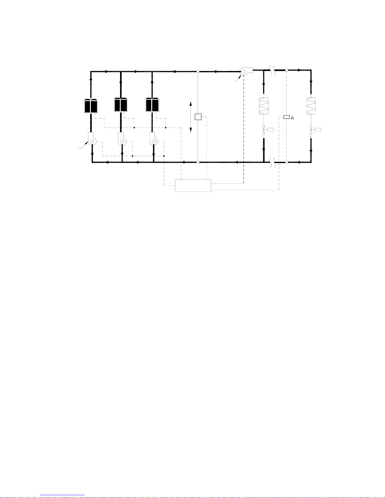
C. Single or multiple chillers with constant water flow through chillers and variable water flow through load
system (primary/secondary pumping arrangement):
A
CHWS
Flow Sensor
Variable
CHWR
Load
2-Way
Valve
Load
P
2-Way
Valve
Constant Speed
Primary Pump
Speed Secondary Pump
Chiller
B
System
Controller
This system is called a Primary – Secondary System and in this arrangement, the generation zone is separated from the
transportation or distribution zone. In this type of arrangement also, constant water flow through the chillers is maintained, however the quantity of water flowing through the load distribution pump/piping system decreases in proportion to
the load and the difference amount is directed through a bypass pipe that connects the supply and return headers. This
bypass pipe forms a ‘Hydraulic Coupling’ between the points A – B and is also called as Common Bridge or Decoupling
Line. The sequence of operation is similar as the foregoing system with the following explanation:
The speed of the secondary chiller pump is controlled by the differential pressure sensor/transmitter, maintaining the
desired differential pressure (∆P) across the cooling coils, their control valves and the branch piping. This pump speed is
modulated within a broad range in order to reduce the pumping head and alter the water flow rate based on the changing
load conditions.
The primary pumps are constant speed pumps and the design flow rate through the chillers remains constant. Each
chiller-pump combination operates independently from the remaining chillers and each pump is shutdown when the
respective chiller is stopped. The sequencing of chillers is dependent on water flow. If greater flow is demanded than that
supplied by the chiller-pumps, return water is forced through the bypass into the supply header. This flow indicates a
need for additional chiller capacity and another chiller-pump starts. Excess bypass flow with reference to the set points in
the system controller in the opposite direction i.e., into the return header indicates overcapacity and the chiller-pumps are
turned off.
Energy is saved because the system head and water flow rate are reduced on the Secondary Pump when there are
partial cooling loads on the system and due to cycling of Primary Pumps.
UNIT LOCATION AND INSTALLATION
These chillers are designed for outdoor installation and can be installed at ground level or on a suitable rooftop location.
In order to achieve good operation, performance and trouble-free service, it is essential that the proposed installation
location and subsequent installing procedures meet the following requirements:
• The most important consideration while deciding upon the location of air cooled chillers is the provision for supply of
adequate ambient air to the condenser and removal of heated discharge air from the condenser. This is accomplished
by maintaining sufficient clearances which have been specified in this Catalog around the units and avoiding obstructions in the condenser air discharge area to prevent the possibility of warm air circulation. Further, the condenser fans
are propeller type and are not recommended for use with ductwork or other hindrances in the condenser air stream.
Where these requirements are not complied, the supply or discharge airflow restrictions or warm air recirculation will
cause higher condensing temperatures resulting in poor unit operation, higher power consumption and possible eventual failure of equipment.
39
Page 41

•
The unit’s longitudinal axis should be parallel to the prevailing wind direction in order to ensure a balanced air flow
through the condenser coils. Consideration should also be given to the possibility of down-drafts caused by adjacent
buildings, which may cause recirculation or uneven unit airflow. For locations where significant cross winds are expected, an enclosure of solid or louver type is recommended to prevent wind turbulence interfering with the unit airflow.
When units are installed in an enclosure, the enclosure height should not exceed the height of the unit.
•
The location should be selected for minimum sun exposure and away from hot air sources, steam, exhaust vents and
sources of airborne chemicals that could attack the condenser coils and steel parts of the unit. Avoid locations where
the sound output and air discharge from the units may be objectionable.
•
If the location is an area which is accessible to unauthorized persons, steps must be taken to prevent access to the unit
by means of a protective fence. This will help to prevent the possibility of vandalism, accidental damage or possible
harm caused by unauthorized removal of panels or protective guards exposing rotating or high voltage components.
•
The clearance requirements prescribed above are necessary to maintain good airflow and provide access for unit
operation and maintenance. However, it is also necessary to consider access requirements based on practical considerations for servicing, cleaning and replacing large components.
•
The unit must be installed on a ONE-PIECE, FLAT and LEVELLED {within 1/2'' (13 mm) over its length and width} /
CONCRETE BASE that extends fully to support the unit. The carrying or supporting structure should be capable of
handling complete operating weight of the unit as given in the Physical Data tables in this Catalog.
•
For ground level installations, it must be ensured that the concrete base is stable and does not settle or dislocate upon
installation of the unit which can strain the refrigerant lines resulting in leaks and may also cause compressor oil return
problems. It is recommended that the concrete slab is provided with appropriate footings. The slab should not be
connected to the main building foundation to avoid noise and vibration transmission.
•
For rooftop installations, choose a place with adequate structural strength to safely support the entire operating weight
of the unit. The unit shall be mounted on a concrete slab similar to ground installations. The roof must be reinforced for
supporting the individual point loads at the mounting isolator locations. It must be checked and ensured that the
concrete base is perfectly horizontal and levelled, especially if the roof has been pitched to aid in water removal. It
should be determined prior to installation if any special treatment is required to assure a levelled installation else it
could lead to the above mentioned problems.
•
Vibration isolators are necessary for installing these chillers in order to minimize the transmission of vibrations. The
two types of vibration isolators generally utilized for mounting these units are Neoprene Pads and Spring Isolators.
Neoprene Pads are recommended for ground level normal installations jobs where vibration isolation is not critical and
job costs must be kept to a minimum. Spring Isolators are recommended for ground level installations which are noisesensitive areas or exposed to wind loads and all roof top installations. For critical installations (extremely noise and
vibration sensitive areas), follow the recommendations of structural and acoustical consultants.
•
Based on the specific project requirements, choose the type of vibration isolators best suited for the application. Carefully select the vibration isolators’ models / configuration based on the respective point loads and place each mount in
its correct position following the Load Distribution Data and Mounting Drawings provided in this Catalog. Refer to the
Schematic Mounting Layout drawings provided in the IOM manual of these chillers for further details in this regard.
COOLER PIPING CONNECTIONS
The following pertinent guidelines are served to ensure satisfactory operation of the units. Failure to follow these recommendations may cause improper operation and loss of performance, damage to the unit and difficulty in servicing and
maintenance:
•
Water piping must be connected correctly to the unit i.e., water must enter from the inlet connection on the cooler and
leave from the outlet connection.
•
A flow switch must be installed in the field piping at the outlet of the cooler (in horizontal piping) and wired back to the unit
control panel using shielded cable. There should be a straight run of piping of at least five pipe diameters on either side
of the flow switch. Paddle type flow switches can be obtained from COOLINE which are supplied as optional items.
•
The chilled water pump(s) installed in the piping system should discharge directly into the unit cooler. The pump(s)
may be controlled external to the unit - but an interlock must be wired to the unit control panel (as shown in the wiring
diagram) so that the unit can start only upon proof of pump operation.
40
Page 42
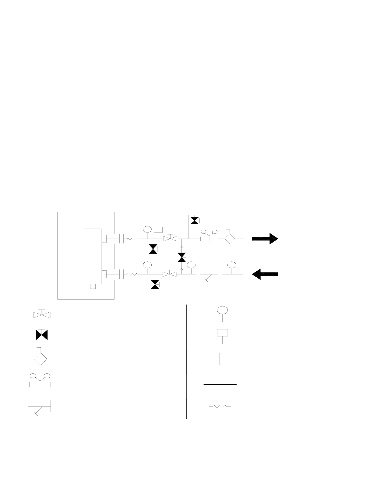
•
Flexible connections suitably selected for the fluid and pressure involved should be provided as mandatory in order to
minimize transmission of vibrations to the piping / building as some movement of the unit can be expected during
normal operation. The piping and fittings must be separately supported to prevent any loading on the cooler.
•
The cooler must be protected by a strainer, preferably of 20 mesh, fitted as close as possible to the liquid inlet connection, and provided with a means of local isolation.
•
Thermometer and pressure gauge connections should be provided on the inlet and outlet connections of each cooler.
Pressure gauges are recommended to check the water pressure before and after the cooler and to determine if any
variations occur in the cooler and system. When installing pressure taps to measure the amount of pressure drop
across the water side of the cooler, the taps should be located in the water piping a minimum of 24 inches downstream
from any connection (flange etc.) but as near to the cooler as possible.
•
Drain and air vent connections should be provided at all low and high points in the piping system to permit complete
drainage of the cooler and piping as well as to vent any air in the pipes. Hand shut-off valves are recommended for use
in all lines to facilitate servicing.
•
The system water piping must be flushed thoroughly before connecting to the unit cooler. The cooler must not be
exposed to flushing velocities or debris released during flushing. It is recommended that a suitably sized bypass and
valve arrangement is installed to allow flushing of the piping system. The bypass can be used during maintenance to
isolate the cooler without disrupting flow to other units.
•
The following is a suggested piping arrangement at the chiller for single unit installations. For multiple chiller installations, each unit should be piped as shown:
Isolating Valve - Normally Open
Isolating Valve - Normally Closed
Balancing Valve
Flow meter
Strainer
OUT
IN
Pressure tapping
Flow Switch
Connection (flanged / Victaulic)
Pipe work
Flexible connection
Note: For chillers with two coolers, the connecting pipes for entering and leaving water on one cooler must be joined to
the corresponding pipes on the other cooler before connecting to the main headers in the system piping.
41
Page 43
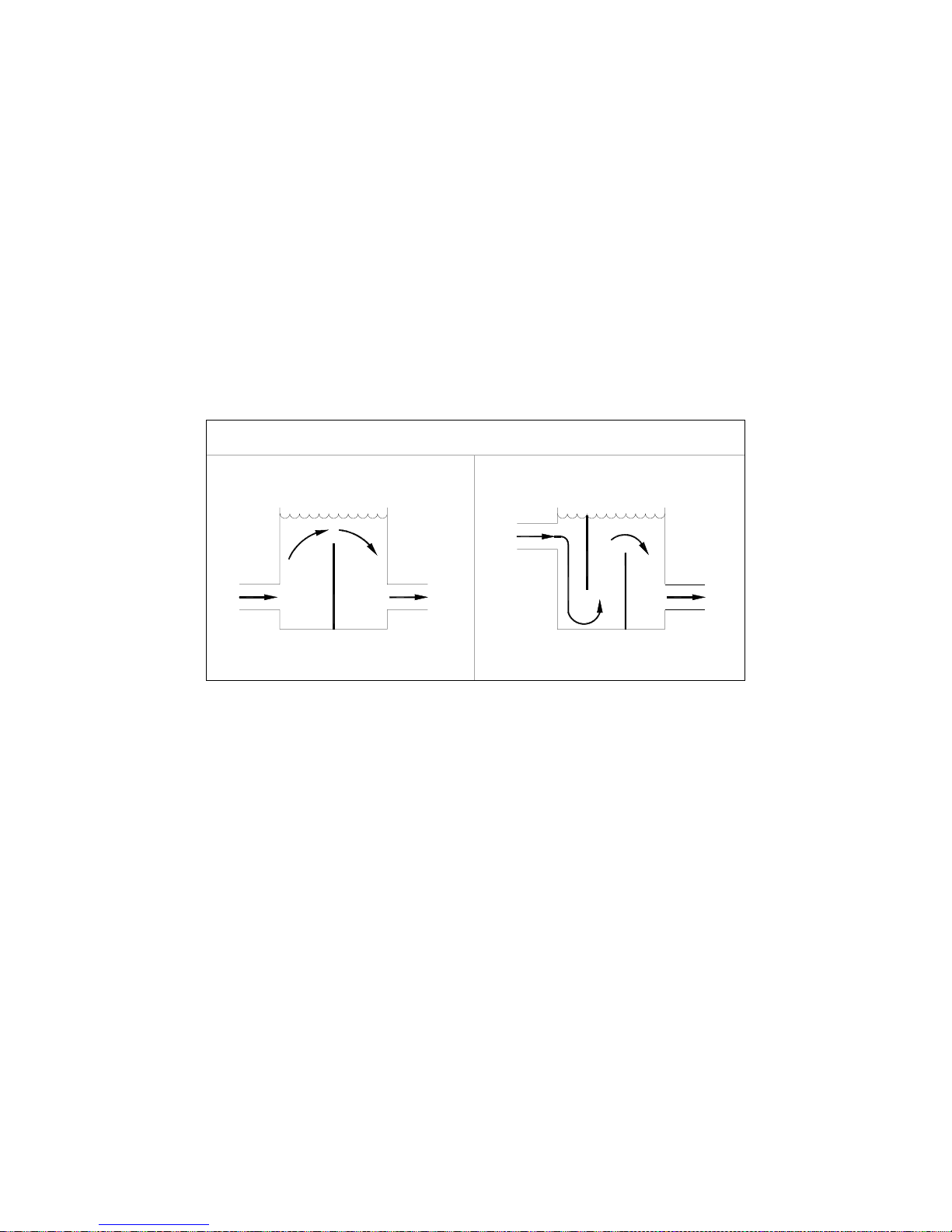
CHILLED FLUID VOLUME REQUIREMENT
The volume of water in a piping system loop is critical to the smooth and proper operation of a chilled water system. If
sufficient volume of water is not there in the system, the temperature control can be lost resulting in erratic system
operation and excessive compressor cycling. Therefore, to prevent this effect of a ‘Short Water Loop’ ensure that total
volume of water in the piping system loop equals or exceeds 3 Gallons per Nominal Ton of cooling capacity for standard
air conditioning applications and 6 Gallons per Nominal Ton of cooling capacity for process cooling jobs where accuracy
is vital and applications requiring operation at very low ambient temperatures and low loading conditions.
For example, chiller model ASQ100B operating with a design water flow rate of 205 GPM for a standard air conditioning
application would require 100 (Nom. Cap.) x 3 = 300 Gallons of water in the piping system loop.
To achieve the aforementioned water volume requirements, it may be necessary to install a tank in the piping system loop to
increase the volume of water in the system and therefore, reduce the rate of change of return water temperature. This tank
should be provided on the return water side to the chiller and the tank should be baffled to ensure that there is no stratification
and the entering stream thoroughly mixes with the tank water. See recommended tank design schematics below:
TANK SCHEMATIC
SUGGESTIONS ON SYSTEM DESIGN AND PIPING PRACTICES
The prospective chilled water system should be designed to the specific requirements of the owner and to achieve the
most efficient system possible. Following are some recommendations:
•
The first decision a designer of a chilled water system must make is the selection of the temperature differential.
Temperature differential is the difference between the supply water and the return water temperatures. There is no one
temperature difference for all chilled water systems. The actual temperature difference that is selected for a specific
installation is determined by the cost of the cooling coils for various temperature differences and the effect that higher
differences may have on the operating cost of the chillers. A careful balance between energy savings and first cost
should be made by the designer. These are the decisions that must be made by the designer for each application and
only experienced designers should entertain water temperature differences in excess of 12
tems. A number of conditions must be recognized before making the final selection of temperature differential:
a) An increase in temperature differential decreases water flow and therefore saves pumping energy.
b) An increase in temperature differential may increase the cost of cooling coils that must operate with a higher mean
temperature difference.
c) Higher temperature differentials increase the possibilities of loss of temperature difference in coils due to dirt on the
air side and chemical deposits on the water side of them.
d) Laminar flow on the water side due to lower velocities at low loads on a coil is always a concern of the water system
designer. The possibility of laminar flow is greater with higher temperature differences. Laminar flow reduces the
heat-transfer rate and should not occur in a coil at any point in its load range. Many systems operate inefficiently
because of coils that were selected at too low a friction loss through them at design load; therefore, at reduced
loads and flows, they operate with laminar flow.
0
F on chilled water sys-
42
Page 44

•
Control of Return Water Temperature: Return water temperature is one of the most important operating values for a
chilled water system. It tells the operator just how good a job the control system and coils are doing in converting
energy from the chillers to the air or water systems that are cooling the building. This is such a basic criterion that it
should be addressed early in the design of a chilled water system. The proper method of controlling return temperature
is through the correct selection of control valves and cooling coils. In conclusion, one of the designer’s most important
tasks is the selection of a sound temperature differential that will provide maximum possible system efficiency. The
second step in this process is to ensure that the differential is maintained after the system is commissioned.
•
The water system should be configured to distribute the water efficiently with a minimum use of energy-wasting
devices. These devices are listed here:
a) Three-way temperature control valves
b) Balancing valves, manual or automatic
c) Pressure-reducing or pressure-regulating valves
•
The piping should be designed without
a) Reducing flanges or threaded reducing couplings
b) Bullhead connections (e.g., two streams connected to the run connections of a tee with the discharge on the branch
of the tee)
•
The friction for the piping should be calculated for all pipe runs, fittings and valves.
•
Cooling coils should be selected with a high enough water velocity in the tubes to avoid laminar flow throughout the
normal load range imposed on the coils.
•
Coil control valves and their actuators should be sized to ensure that they can operate at all loads on the system
without lifting the valve head off the valve seat.
•
Expansion tank should be provided to so that water volume changes can be accommodated. Expansion tanks are
generally connected to the suction side of the pump - lowest pressure point.
•
Pumps in parallel must always operate at the same speed. There may be some exceptional cases where parallel
pumps are operated at different speeds, but only experienced designers should make evaluations for such a proposed
operation. Also, it is better to use pumps of the same size when operating them in parallel. Variable speed pumps
should be controlled so that pumps operating in parallel never have more than one percent difference in actual operating speed. Mixing of constant and variable speed pumps in parallel operation is wrong and leads to disastrous
results.
•
Distribution pumps should be selected for maximum efficiency at the design condition and within the economic constraints of the project. Distribution pumps should be added and subtracted to avoid operation of pumps at points of
high thrust and poor efficiency. Pump sequencing should achieve maximum possible system efficiency.
•
Differential pressure control (bypass) valves should never be installed at the pump discharges.
•
Check valves should be provided in pump discharges when pumps are operating in parallel. Pump discharge check
valves should be center guided, spring loaded, disc type check valves and should be sized so that the check valve is
full open at design flow rate. Generally this will require the check valve to be one pipe size smaller than the connecting
piping.
•
Circuiting Chilled water to Multiple Chillers : There are fundamentals for the circuiting of chillers that should not be
violated in order to achieve maximum efficiency. Some of these are:
a) Design the piping arrangement so that energy consumption of chillers is not increased.
b) Arrange the piping so that all chillers receive the same return water temperature.
c) Ensure that the required design water flow through the coolers is always maintained.
43
Page 45
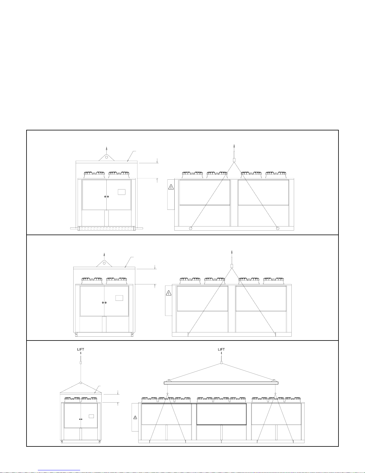
RIGGING INSTRUCTIONS
ATTENTION TO RIGGERS
Hook rigging sling thru holes in base rail, as shown below.
Holes in base rail are centered around the unit center of gravity.
Center of gravity is not unit center line.
Ensure center of gravity aligns with the main lifting point before lifting.
Use spreader bar when rigging, to prevent the slings from damaging the unit.
CAUTION
All panels should be in place when rigging.
Care must be taken to avoid damage to the coils during handling.
Insert packing material between coils & slings as necessary.
MODELS: ASQ045B - ASQ200B
LIFT
SPREADER BAR
PROPER CLEARANCE
TO BE PROVIDED
LIFT
LIFT
SPREADER BAR
PROPER CLEARANCE
TO BE PROVIDED
MODELS: ASQ220B - ASQ280B
LIFT
SPREADER BAR
PROPER CLEARANCE
TO BE PROVIDED
MODELS: ASQ300B - ASQ440B
44
Page 46
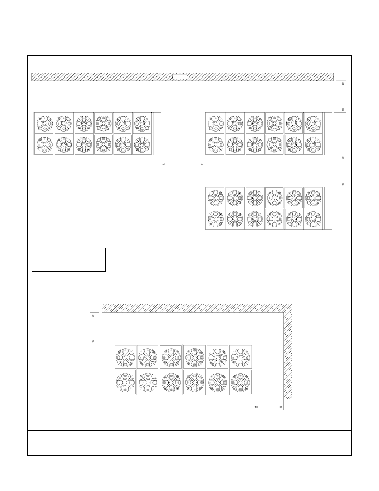
INSTALLATION CLEARANCE
WALL
2000
A B
MODEL NUMBER A B
ASQ045B - ASQ070B 2500 2000
ASQ080B - ASQ280B 3000 2000
ASQ300B - ASQ440B 3500 2500
B
FIGURE - 1
STRAIGHT WALL
2000
FIGURE - 2
CORNER WALL
NOTE: 1. All dimensions are in mm.
2. If unit is installed in special pit, please observe the same tolerance for walls. Pit height should not exceed
the unit height.
45
Page 47
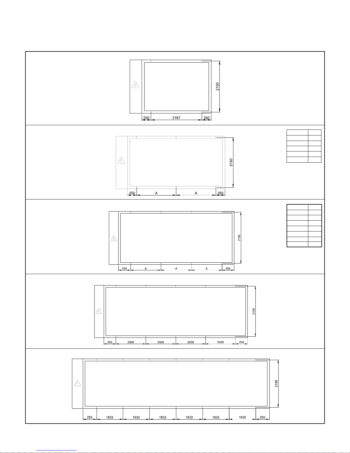
MODELS: ASQ045B - ASQ070B
MOUNTING LOCATION
MODELS: ASQ080B - ASQ130B
MODELS: ASQ140B - ASQ200B
MODELS: ASQ220B - ASQ280B
MODEL A
ASQ080B 1249
ASQ090B 1249
ASQ100B 1249
ASQ115B 1858
ASQ130B 1858
MODEL A
ASQ140B 1586
ASQ150B 1586
ASQ160B 2094
ASQ170B 2094
ASQ180B 2094
ASQ190B 2094
ASQ200B 2094
MODELS: ASQ300B - ASQ440B
NOTE: All dimensions are in mm.
46
Page 48
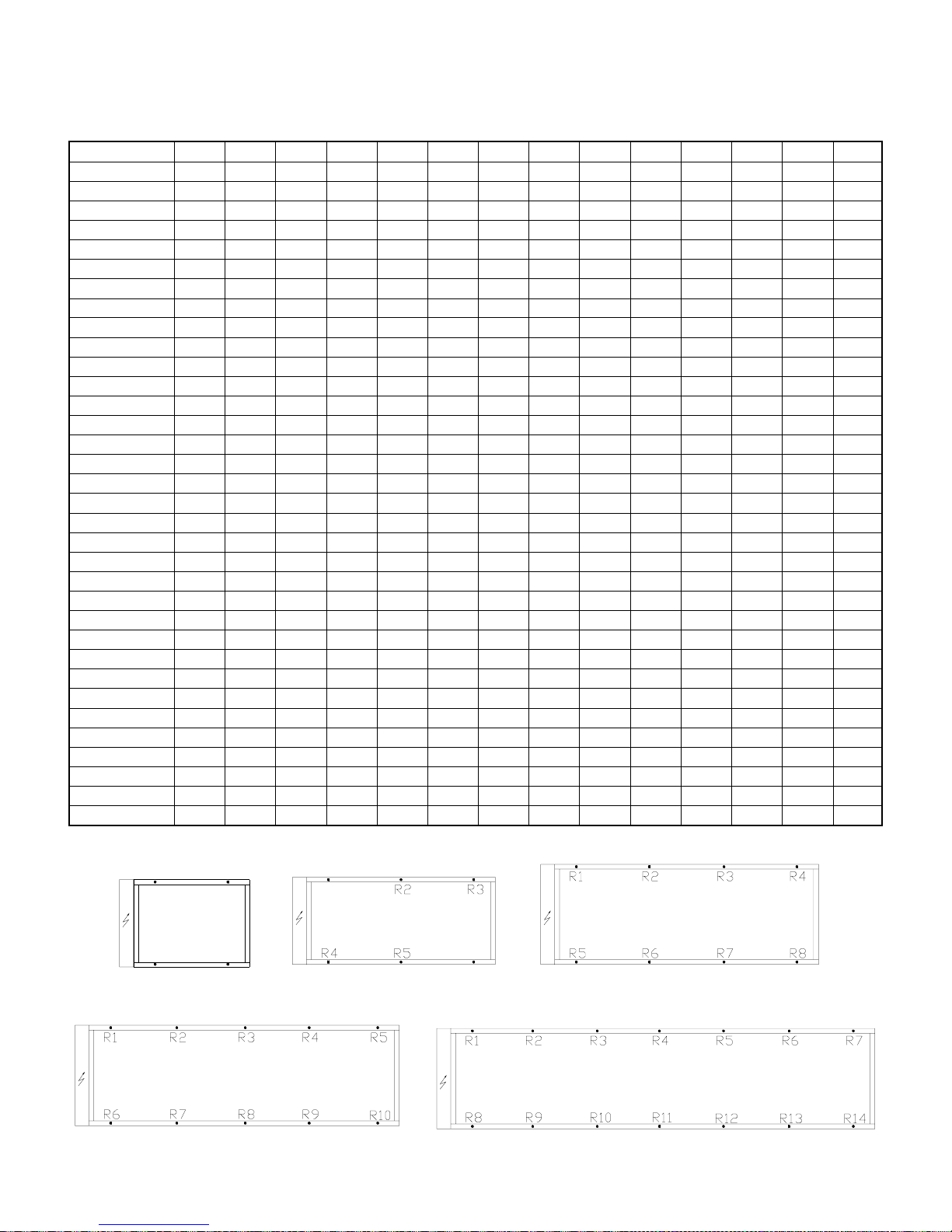
LOAD DISTRIBUTION, kg. (ALUMINUM CONDENSER COIL)
MODEL No. R1 R2 R3 R4 R5 R6 R7 R8 R9 R10 R11 R12 R13 R14
ASQ045B 520 504 496 453 - - - - - - - - - ASQ050B 523 507 499 455 - - - - - - - - - ASQ055B 650 634 626 524 - - - - - - - - - ASQ060B 655 639 631 527 - - - - - - - - - ASQ070B 686 670 662 555 - - - - - - - - - ASQ080B 594 563 547 493 462 446 - - - - - - - ASQ090B 626 594 578 538 507 491 - - - - - - - ASQ100B 779 748 732 615 584 568 - - - - - - - -
ASQ115B 877 845 830 722 691 675 - - - - - - - ASQ130B 885 853 837 726 695 679 - - - - - - - ASQ140B 734 707 698 688 640 612 603 594 - - - - - ASQ150B 754 726 717 708 657 629 620 611 - - - - - ASQ160B 968 934 923 911 799 765 754 742 - - - - - ASQ170B 985 951 939 928 813 779 768 756 - - - - - ASQ180B 998 963 952 940 823 788 777 765 - - - - - ASQ190B 1002 967 956 945 827 793 781 770 - - - - - ASQ200B 1003 969 958 946 828 794 782 771 - - - - - ASQ220B 1046 1012 995 989 983 862 828 811 805 799 - - - ASQ230B 1050 1016 998 993 987 864 830 813 807 801 - - - ASQ240B 1057 1023 1006 1000 994 871 836 819 813 808 - - - ASQ250B 1075 1040 1023 1017 1012 887 852 835 829 824 - - - ASQ260B 1114 1080 1063 1057 1051 966 931 914 908 903 - - - ASQ270B 1119 1084 1067 1062 1056 968 934 916 911 905 - - - ASQ280B 1123 1089 1071 1066 1060 970 936 918 913 907 - - - ASQ300B 1064 1046 1037 1027 1018 1014 1009 872 854 845 836 827 822 817
ASQ320B 1077 1058 1049 1040 1031 1026 1022 882 864 854 845 836 831 827
ASQ330B 1078 1060 1051 1041 1032 1028 1023 883 864 855 846 837 832 828
ASQ340B 1082 1063 1054 1045 1036 1031 1027 885 866 857 848 839 834 830
ASQ350B 1125 1105 1095 1085 1075 1070 1065 928 908 898 888 878 873 868
ASQ360B 1129 1109 1099 1089 1079 1074 1069 930 910 900 890 880 875 870
ASQ380B 1134 1114 1104 1094 1084 1079 1074 935 915 905 895 885 880 875
ASQ400B 1137 1117 1107 1097 1087 1082 1077 937 917 907 897 887 882 877
ASQ420B 1167 1147 1137 1127 1117 1112 1107 991 971 961 951 941 936 931
ASQ440B 1172 1152 1142 1132 1122 1117 1112 993 973 963 953 943 938 933
R1
R3
R2
R4
R1
R6
47
Page 49
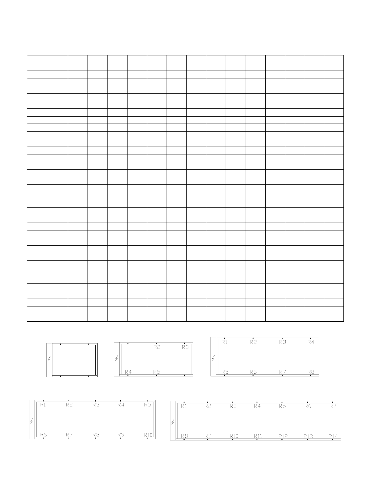
LOAD DISTRIBUTION, kg. (COPPER CONDENSER COIL)
MODEL No. R1 R2 R3 R4 R5 R6 R7 R8 R9 R10 R11 R12 R13 R14
ASQ045B 551 535 527 484 - - - - - - - - - ASQ050B 554 538 531 486 - - - - - - - - - ASQ055B 698 682 675 572 - - - - - - - - - ASQ060B 703 687 679 575 - - - - - - - - - ASQ070B 756 740 732 625 - - - - - - - - - ASQ080B 631 599 584 530 499 483 - - - - - - - ASQ090B 679 647 632 592 560 545 - - - - - - - ASQ100B 832 801 785 669 637 621 - - - - - - - ASQ115B 951 920 904 796 765 749 - - - - - - - ASQ130B 959 928 912 800 769 753 - - - - - - - ASQ140B 782 755 746 736 688 661 651 642 - - - - - ASQ150B 824 796 787 778 727 699 690 681 - - - - - ASQ160B 1026 992 980 969 857 823 811 800 - - - - - ASQ170B 1060 1026 1014 1003 889 854 843 831 - - - - - ASQ180B 1081 1047 1036 1024 906 872 861 849 - - - - - ASQ190B 1086 1051 1040 1028 911 877 865 854 - - - - - ASQ200B 1087 1053 1041 1030 912 878 866 855 - - - - - ASQ220B 1113 1079 1061 1056 1050 929 895 878 872 866 - - - ASQ230B 1117 1082 1065 1060 1054 931 897 880 874 868 - - - ASQ240B 1132 1097 1080 1074 1069 945 911 893 888 882 - - - ASQ250B 1172 1137 1120 1114 1109 984 949 932 926 921 - - - ASQ260B 1211 1177 1160 1154 1148 1063 1028 1011 1005 1000 - - - ASQ270B 1216 1181 1164 1159 1153 1065 1031 1013 1008 1002 - - - ASQ280B 1220 1186 1168 1163 1157 1067 1033 1015 1010 1004 - - - ASQ300B 1152 1134 1125 1116 1107 1102 1097 961 942 933 924 915 910 906
ASQ320B 1175 1156 1147 1138 1129 1124 1120 980 962 953 943 934 930 925
ASQ330B 1176 1158 1149 1140 1130 1126 1121 981 962 953 944 935 930 926
ASQ340B 1180 1162 1152 1143 1134 1130 1125 983 964 955 946 937 932 928
ASQ350B 1244 1224 1214 1204 1194 1189 1184 1046 1026 1016 1006 996 991 986
ASQ360B 1248 1228 1218 1208 1198 1193 1188 1048 1028 1018 1008 998 993 988
ASQ380B 1252 1232 1222 1212 1202 1197 1192 1054 1034 1024 1014 1004 999 994
ASQ400B 1256 1236 1226 1216 1206 1201 1196 1055 1035 1025 1015 1005 1000 995
ASQ420B 1286 1266 1256 1246 1236 1231 1226 1109 1089 1079 1069 1059 1054 1049
ASQ440B 1291 1271 1261 1251 1241 1236 1231 1112 1092 1082 1072 1062 1057 1052
R1
R3
R2
R4
R1
R6
48
Page 50

 Loading...