

Page 1
700W
RS-700-AAAA-A3 User s Manual
Ver 1.0: 2008/03
2008
使用说明书/中文
Page 2

Disposal of Waste Equipment by Users in Private Households in the European Union.
This symbol on the product or on its packaging indicates that this product must not be
disposed of with your other household waste. Instead, it is your responsibility to
dispose of your waste equipment by handing it over to a designated collection point
for the recycling of waste electrical and electronic equipment. The separate collection
and recycling of your waste equipment at the time of disposal will help to conserve
natural resources and ensure that it is recycled in a manner that protects human
health and the environment. For more information about where you can drop off your
waste equipment for recycling, please contact your local city office, your household
waste disposal service or the shop where you purchased the product.
Evacuation des équipements usagés par les utilisateurs dans les foyers privés au sein
de l'Union européenne
La présence de ce symbole sur le produit ou sur son emballage indique que vous ne
pouvez pas vous débarasser de ce produit de la même façon que vos déchets
courants. Au contraire, vous êtes responsable de l'évacuation de vos équipements
usagés et à cet effet, vous êtes tenu de les remettre à un point de collecte agréé pour
le recyclage des équipements électriques et électroniques usagés. Le tri, l'évacuation
et le recyclage séparés de vos équipements usagés permettent de préserver les
ressources naturelles et de s'assurer que ces équipements sont recyclés dans le
respect de la santé humaine et de l'environnement. Pour plus d'informations sur les
lieux de collecte des équipements usagés, veuillez contacter votre mairie, votre
service de traitement des déchets ménagers ou le magasin où vous avez acheté le
produit.
Entsorgung von Elektrogeräten durch Benutzer in privaten Haushalten in der
EUDieses Symbol auf dem Produkt oder dessen Verpackung gibt an, dass das
Produkt nicht zusammen mit dem Restmüll entsorgt werden darf. Es obliegt
daher Ihrer Verantwortung, das Gerät an einer entsprechenden Stelle für die
Entsorgung oder Wiederverwertung von Elektrogeräten aller Art abzugeben
(z.B. ein Wertstoffhof). Die separate Sammlung und das Recyceln Ihrer alten
Elektrogeräte zum Zeitpunkt ihrer Entsorgung trägt zum Schutz der Umwelt bei
und gewährleistet, dass sie auf eine Art und Weise recycelt werden, die keine
Gefährdung für die Gesundheit des Menschen und der Umwelt darstellt. Weitere
Informationen darüber, wo Sie alte Elektrogeräte zum Recyceln abgeben können,
erhalten Sie bei den örtlichen Behörden, Wertstoffhöfen oder dort, wo Sie das
Gerät erworben haben.
English
Français
Deutsch
Page 3

Smaltimento di apparecchiature da rottamare da parte di privati nell'Unione Europea
Questo simbolo che appare sul prodotto o sulla confezione indica che il prodotto non
Italiano
Português
Español
deve essere smaltito assieme agli altri rifiuti domestici. Gli utenti devono provvedere
allo smaltimento delle apparecchiature da rottamare portandole al luogo di raccolta
indicato per il riciclaggio delle apparecchiature elettriche ed elettroniche. La raccolta e
il riciclaggio separati delle apparecchiature da rottamare in fase di smaltimento
favoriscono la conservazione delle risorse naturali e garantiscono che tali
apparecchiature vengano rottamate nel rispetto dell'ambiente e della tutela della
salute. Per ulteriori informazioni sui punti di raccolta delle apparecchiature da
rottamare, contattare il proprio comune di residenza, il servizio di smaltimento dei
rifiuti locale o il negozio presso il quale è stato acquistato il prodotto.
Descarte de equipamentos por usuários em residências da União Européia
Este símbolo no produto ou na embalagem indica que o produto não pode ser
descartado junto com o lixo doméstico. No entanto, é sua responsabilidade levar os
equipamentos a serem descartados a um ponto de coleta designado para a reciclagem
de equipamentos eletro-eletrônicos. A coleta separada e a reciclagem dos
equipamentos no momento do descarte ajudam na conservação dos recursos naturais
e garantem que os equipamentos serão reciclados de forma a proteger a saúde das
pessoas e o meio ambiente. Para obter mais informações sobre onde descartar
equipamentos para reciclagem, entre em contato com o escritório local de sua cidade,
o serviço de limpeza pública de seu bairro ou a loja em que adquiriu o produto.
Eliminación de residuos de aparatos eléctricos y electrónicos por parte de usuarios
domésticos en la Unión Europea
Este símbolo en el producto o en el embalaje indica que no se puede desechar el
producto junto con los residuos domésticos. Por el contrario, si debe eliminar este tipo
de residuo, es responsabilidad del usuario entregarlo en un punto de recolección
designado de reciclado de aparatos electrónicos y eléctricos. El reciclaje y la
recolección por separado de estos residuos en el momento de la eliminación ayudará a
preservar recursos naturales y a garantizar que el reciclaje proteja la salud y el medio
ambiente. Si desea información adicional sobre los lugares donde puede dejar estos
residuos para su reciclado, póngase en contacto con las autoridades locales de su
ciudad, con el servicio de gestión de residuos domésticos o con la tienda donde
adquirió el producto.
Afvoer van afgedankte apparatuur door gebruikers in particuliere huishoudens in de
Europese Unie
Nederlands
Dit symbool op het product of de verpakking geeft aan dat dit product niet mag
worden afgevoerd met het huishoudelijk afval. Het is uw verantwoordelijkheid uw
afgedankte apparatuur af te leveren op een aangewezen inzamelpunt voor de
verwerking van afgedankte elektrische en elektronische apparatuur. De gescheiden
inzameling en verwerking van uw afgedankte apparatuur draagt bij tot het sparen van
natuurlijke bronnen en tot het hergebruik van materiaal op een wijze die de
volksgezondheid en het milieu beschermt. Voor meer informatie over waar u uw
afgedankte apparatuur kunt inleveren voor recycling kunt u contact opnemen met het
gemeentehuis in uw woonplaats, de reinigingsdienst of de winkel waar u het product
hebt aangeschaft.
Page 4

Contents
Warranty
Important Safeguards
1. Overview
1.1 Introduction
1.2 Key Features
1.3 Model Description
2. Specifications
2.1 Input Specifications
2.2 Output Specifications
2.3 Environments
3. Installation
4. Troubleshooting
5. Connector Descriptions
5.1 Motherboard 24Pin Connector (P1)
5.2 CPU 4+4Pin Connector (P2,P3)
5.3 PCI-e 8Pin Connector
5.4 PCI-e 6Pin Connector
5.5 PCI-e 8Pin Connector
5.6 PCI-e 6Pin Connector
5.7
5.8 Peripheral Connector
5.9 Floppy Connector
-- -- -- -- -- -- -- -- -- ----------- -- -- -- -- -- -- -- -- -- -- -- -- -- -- -- -- -- -- ----------- -- --
-- -- -- -- -- -- -- -- -- ----------- -- -- -- -- -- -- -- -- -- -- -- -- -- --
-- -- -- -- -- -- -- -- -- ----------- -- -- -- -- -- -- -- -- -- -- -- -- -- -- -- -- -- -- ----------- -
-- -- -- -- -- -- -- -- -- ----------- -- -- -- -- -- -- -- -- -- -- -- -- -- -- -- -- -- -- ----
-- -- -- -- -- -- -- -- -- ----------- -- -- -- -- -- -- -- -- -- -- -- -- -- -- -- -- -- -- ---
-- -- -- -- -- -- -- -- -- ----------- -- -- -- -- -- -- -- -- -- -- -- -- -- -- -- --
-- -- -- -- -- -- -- -- -- ----------- -- -- -- -- -- -- -- -- -- -- -- -- -- -- -- -- -- -- -----
-- -- -- -- -- -- -- -- -- ----------- -- -- -- -- -- -- -- -- -- -- -- -- -- -- -
-- -- -- -- -- -- -- -- -- ----------- -- -- -- -- -- -- -- -- -- -- -- -- -- -
-- -- -- -- -- -- -- -- -- ----------- -- -- -- -- -- -- -- -- -- -- -- -- -- -- -- -- -- -- --
-- -- -- -- -- -- -- -- -- ----------- -- -- -- -- -- -- -- -- -- -- -- -- -- -- -- -- -- -- --------
-- -- -- -- -- -- -- -- -- ----------- -- -- -- -- -- -- -- -- -- -- -- -- -- -- -- -- -- -- -
-- -- -- -- -- -- -- -- -- ----------- -- -- -- -- -- -- -- -- -- -- -- -- --
-- -- -- -- -- -- -- -- -- ----------- -- -- -- -- -- -- -- -- -- -- -- -- -- -
-- -- -- -- -- -- -- -- -- ----------- -- -- -- -- -- -- -- -- -- -- -- -- -- --
-- -- -- -- -- -- -- -- -- ----------- -- -- -- -- -- -- -- -- -- -- -- -- -- -
-- -- -- -- -- -- -- -- -- ----------- -- -- -- -- -- -- -- -- -- -- -- -- -- -
SATA Connector
-- -- -- -- -- -- -- -- -- ----------- -- -- -- -- -- -- -- -- -- -- -- -- -- -- -- -- -- -
-- -- -- -- -- -- -- -- -- ----------- -- -- -- -- -- -- -- -- -- -- -- -- -- --
-- -- -- -- -- -- -- -- -- ----------- -- -- -- -- -- -- -- -- -- -- -- -- -- -- -- --
6. Automatic Fan Speed Control
-- -- -- -- -- -- -- -- -- ----------- -- -- -- --
-- -- -- -- -- -- -- -- -- ----------- -- -- -- -- -- -- -
-- -- -- -- -- -- -- -- -- ----------- -- -- -- -- -- -
1
1
2
2
2
2
3
3
3
3
4
4
5
5
5
5
5
6
6
6
6
6
7
Page 5

User Manual / English
Warranty
Cooler Master guarantees this device to be free of defects in material and
workmanship, and provides a 5-year hardware limited warranty for the
power supply on the date of purchase. Please keep your receipt in a safe
place.
This product is designed for computer usage only. Using this device in any
other application will void the warranty. If you are not familiar with
computer hardware installation, please ask for professional assistance.
The warranty is applies to damages caused through normal use and is
void if it is determined that the device was damaged because of abuse,
alteration, misuse, negligence, incorrect voltage supply, air/water
pollution, accidents and natural disasters.
Cooler Master Co., Ltd.
9F., No. 786, Chung-Cheng Rd., Chung-Ho City, Taipei Hsien, Taiwan,
R.O.C.
TEL: +886-2-3234-0050
FAX: +886-2-3234-0051
Http://www.coolermaster.com
Important Safeguards
In order to ensure your own safety, please observe the following
basic rules:
1. Turn off and unplug your PSU from the commercial AC outlet before
cleaning. Do not use liquid or aerosol cleaners. Please use a dry cloth
to clean the outer surface of your PSU.
2. Do not install or operate your computer system near water.
3. PSU should be powered by the source indicated on the rating label.
4. Never spill liquids of any kind on your PSU.
5. If the PSU does not operate normally, please feel free to contact our
service center.
1
Page 6
User Manual / English
1. Overview
1.1 Introduction
UCP---Ultimate Circuit Protection
The power supply is essentially the heart beat of your PC. Cooler Master
recognizes the importance of a quality PSU and has created a new high end
line called UCP---Ultimate Circuit Protection. The look, feel, and design of this
new line is completely different; added features include a unique scratch
resistant coating as well as being eco-friendly certified. An innovative new
internal structure made for performance, and durability allows the PSU to
provide 87% efficiency---a nearly unheard of number! Cooler Master is a firm
believer in customer satisfaction and stands behind its products. A 5 year
warranty and protection plan has been developed with the customer in mind!
Power Supply is a key component to meet all power requirements of PC
operation and maintain continuous stability and reliability of a computer
system. Cooler Master's power supply lets your PC operate more efficiently as
power comes into your PC. It also enhances system reliability by preventing
abnormal supply from spikes and surges. In addition, the power supply
provides your system with perfect protections. The RS-700-AAAA-A3 complies
with Intel ATX 12V V2.3 and EPS 12V V2.92 power supply that offers more
power capacity for CPU usage.
1.2 Key Features
1. Compliance with the newest Intel ATX 12V V2.3
2. Compliance with the newest SSI EPS 12V V2.92
3. Super silent operation with intelligent fan speed control
4. Quad PCI-e connector satisfies high-end graphic card requirements
5. Green power design to meet energy star and blue angel requirements
6. More than 87% efficiency at typical load operation
7. Higher reliability (MTBF > 100,000 Hours)
8. Protection: OVP / OCP / OPP / SCP / UVP / OTP
9. Active power factor correction (PF > 0.9)
10. Real power capacity satisfies high-end system operation
1.3 Model Description
RS-700-AAAA-A3: 700W Active PFC Power Supply
2
Page 7
User Manual / English
2. Specifications
2.1 Input Specifications
1. Type: ATX 12V V2.3 / SSI EPS 12V V2.92
2. Voltage: 90V ~ 264V (Auto Range)
3. Current: 10A @ 115Vac / 5A @ 230Vac
4. Frequency: 47Hz ~ 63Hz
5. Power Good Signal: 100ms ~ 500ms
6. Hold-Up Time: > 17ms
7. Efficiency: > 87%
8. Output Capacity: 700W Continually
9. Peak Capacity: 840W
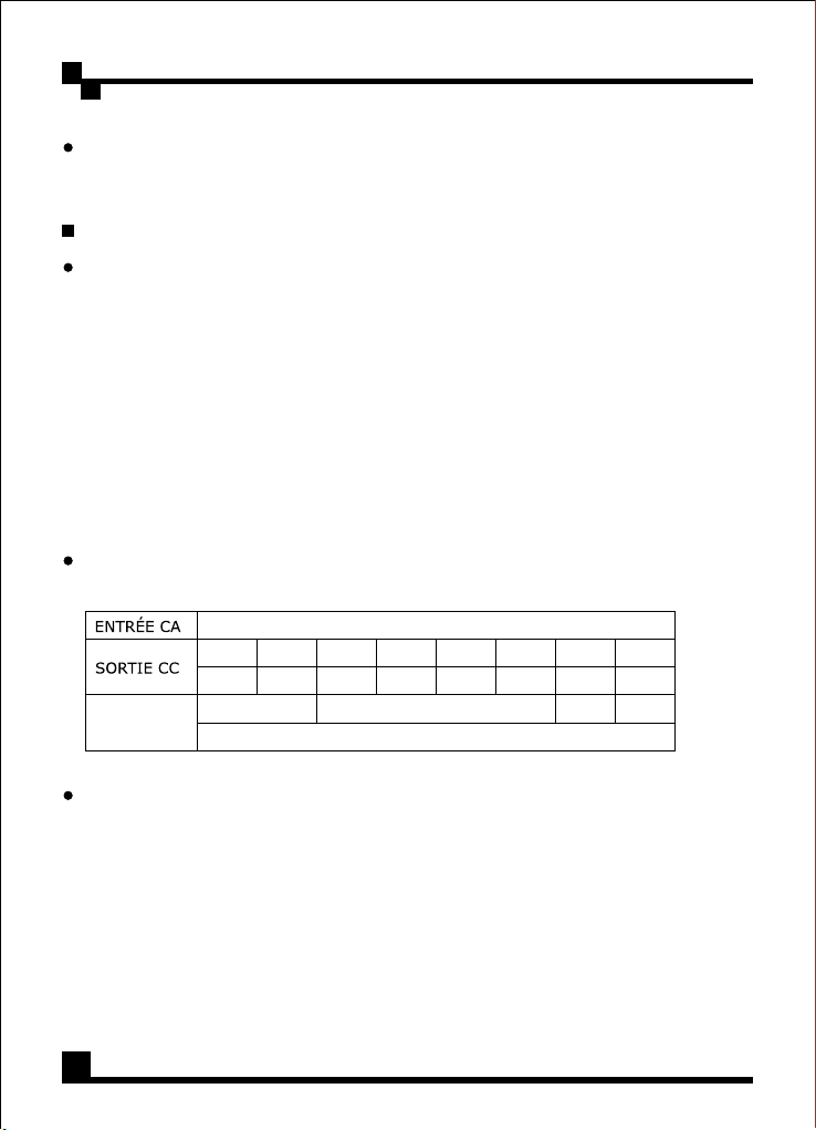
2.2 Output Specifications
RS-700-AAAA-A3
AC Input
DC Output
Total Output
+3.3V
22A
133W
100-240V~ 10-5A 60-50Hz
+5V
+12V1+12V2+12V3+12V
22A
624W
700W
+5V
-12V
4
0.5A
19A19A19A19A
6W
S
3A
15W
2.3 Environments
1. Dimensions: 150(W) x 150(L) x 86(H) (mm)
2. Operation Temperature: 0 ~ 40 C
3. MTBF: > 100,000 Hours
4. EMC: CE / FCC / C-tick
5. Safety: UL / TUV / NEMKO / GOST
o
3
Page 8
User Manual / English
3. Installation
1. Switch off the main switch of the power supply and disconnect the
power cord.
2. Unscrew and open the side panel of the chassis.
3. Disconnect all power connectors from the motherboard and from
peripheral devices such as case fans, hard drives, CD-ROMs, floppy
drives, etc.
4. Replace the power supply.
5. Connect P1 (24Pin) and P2,P3 (CPU 4+4Pin) connectors to your
motherboard.
6. Connect other connectors to your system components.
7. Make sure that all other connectors are also connected.
8. Close the chassis and reattach the case screws.
9. Plug in the power cord of the power supply.
4. Troubleshooting
If your system does not turn on after installing the power supply,
follow the troubleshooting guide as listed below:
1. Please make sure the main power is connected on correctly.
2. Please make sure the P1 and P2 connectors are connected correctly to
the motherboard.
3. If the power supply does not work properly, please contact our service
center immediately.
4
Page 9
User Manual / English
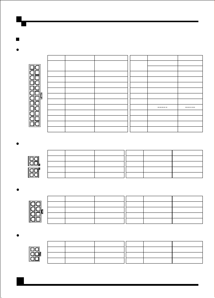
5. Connector Descriptions
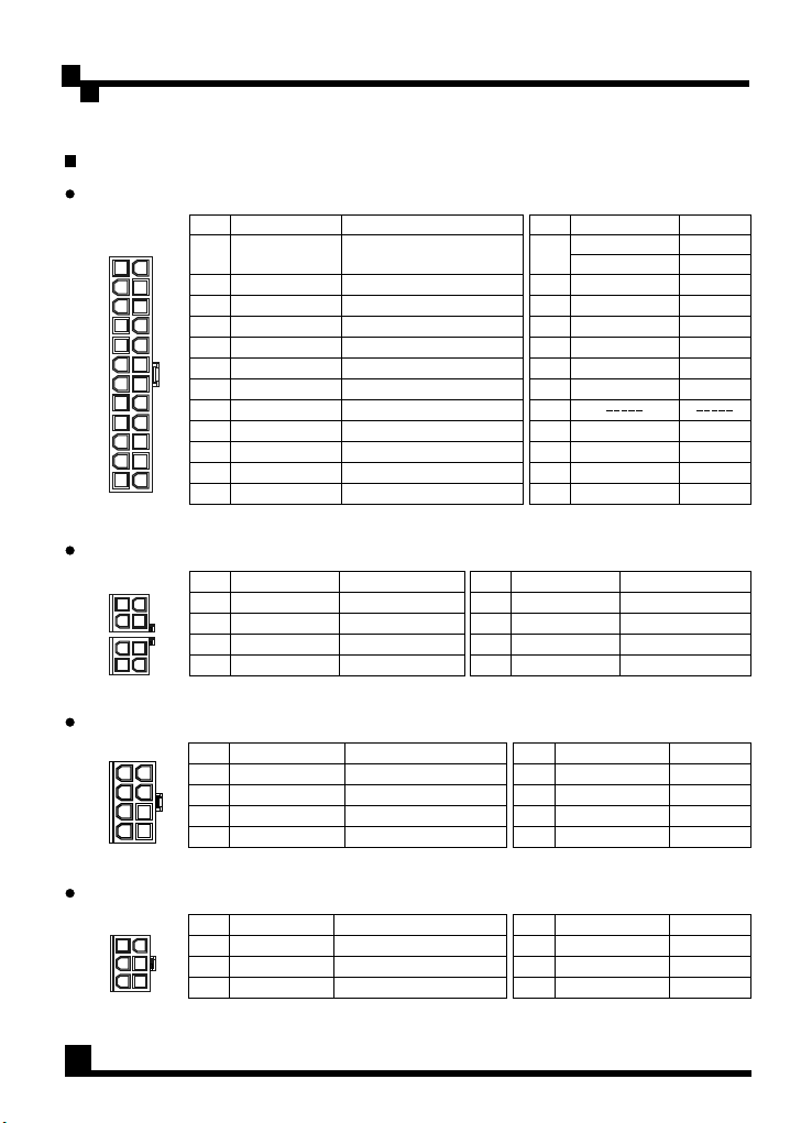
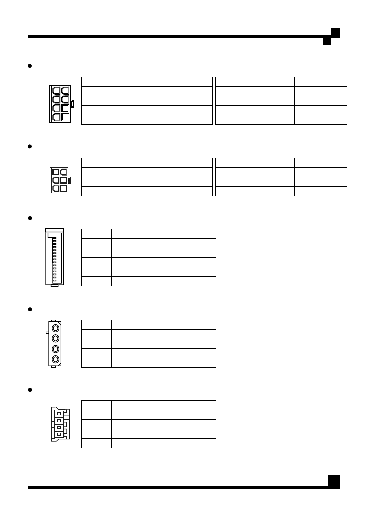
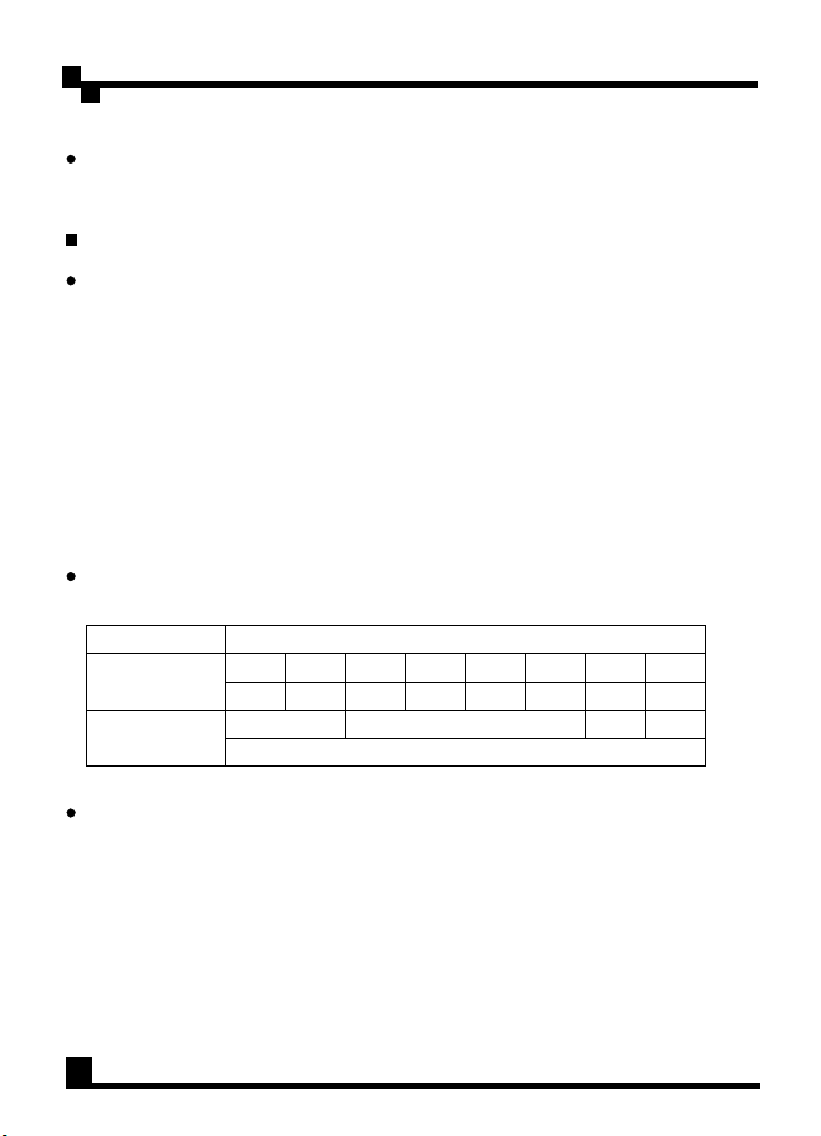
5.1 Motherboard 24Pin Connector (P1)
Description Description
Pin1 Pin13
2
3
4
5
6
7
8
9
10
11
12
1
+3.3V
+3.3V
COM
+5V
COM
+5V
COM
PWR_OK
+5V
sb
+12V
+12V
+3.3V
1
1
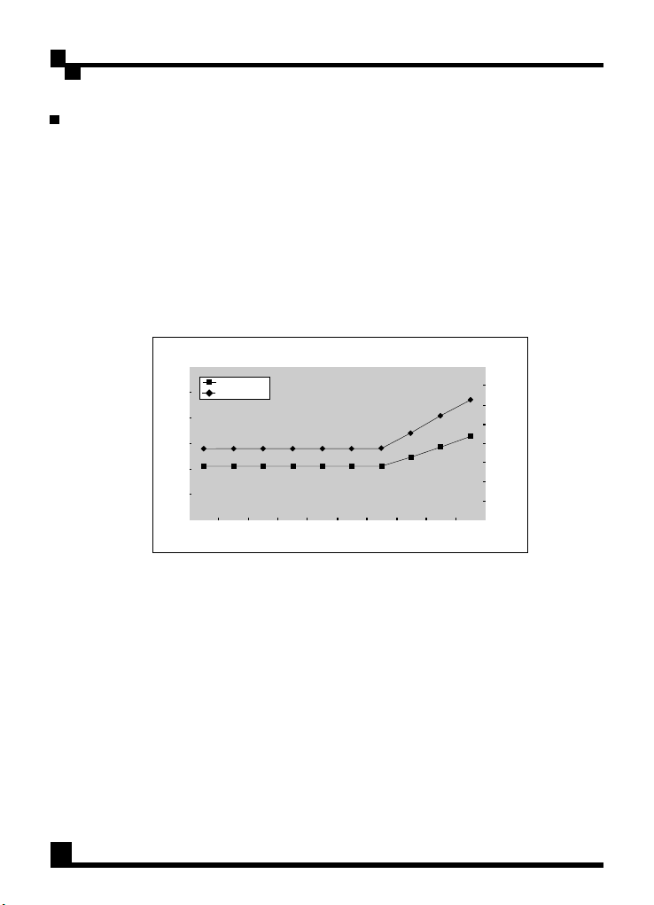
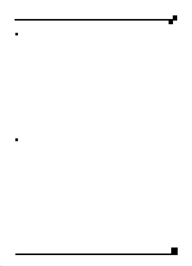
5.2 CPU 4+4Pin Connector (P2,P3)
Pin Pin
Pin1 Pin5
Pin
1
2
3
4
Description
COM
COM
COM
COM
Color
Orange
Orange
Black
Red
Black
Red
Black
Gray
Purple
Yellow / Black Striple
Yellow / Black Striple
Orange
Color
Black
Black
Black
Black
Pin
5
6
7
8
13
14
15
16
17
18
19
20
21
22
23
24
Description
+12V
2
+12V
2
+12V
2
+12V
2
+3.3V
+3.3V
-12V
COM
PS_ON
COM
COM
COM
+5V
+5V
+5V
COM
s
Yellow
Yellow
Yellow
Yellow
Color
Orange
Brown
Blue
Black
Green
Black
Black
Black
Red
Red
Red
Black
Color
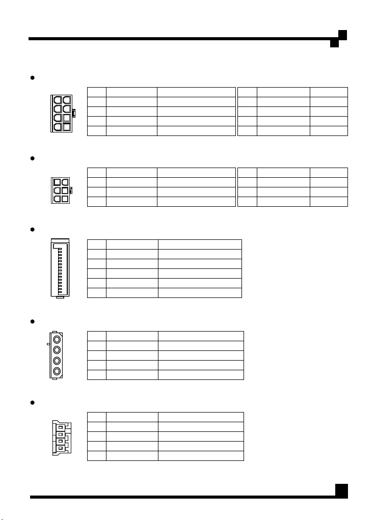
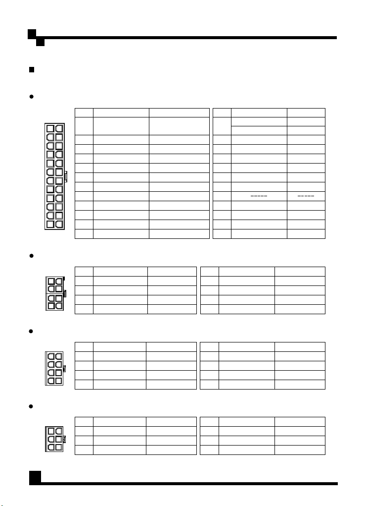
5.3 PCI-e 8Pin Connector
Pin1 Pin5
Description
Pin Pin
+12V
1
2
3
+12V
+12V
3
3
3
4
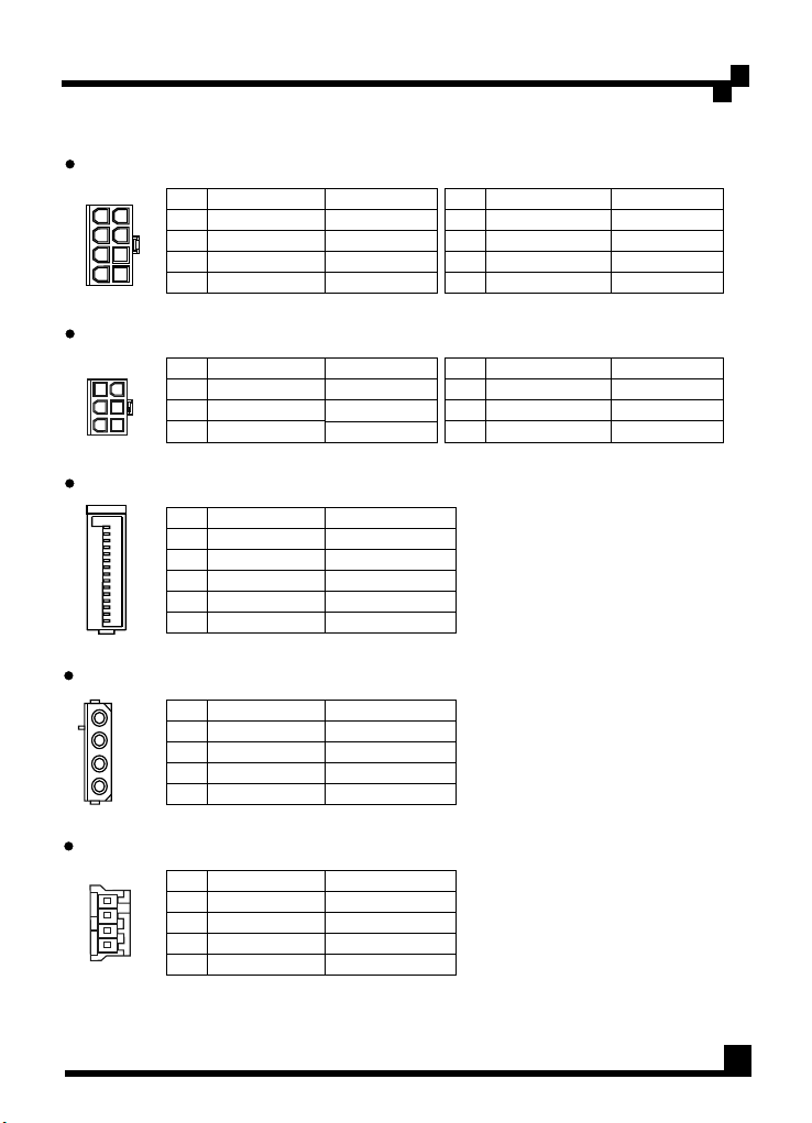
5.4 PCI-e 6Pin Connector
Pin1 Pin4
Description
Pin Pin
+12V
1
2
3
+12V
+12V
3
3
3
5
Color
Yellow / Blue Stripe
Yellow / Blue Stripe
Yellow / Blue Stripe
Black
Color
Yellow / Blue Stripe
Yellow / Blue Stripe
Yellow / Blue Stripe
5
6
7
8
4
5
6
Description
COM
COM
COM
COMCOM
Description
COM
COM
COM
Color
Black
Black
Black
Black
Color
Black
Black
Black
Page 10
User Manual / English
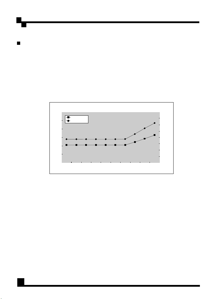
5.5 PCI-e 8Pin Connector
Pin1 Pin5
5.6 PCI-e 6Pin Connector
Pin1 Pin4
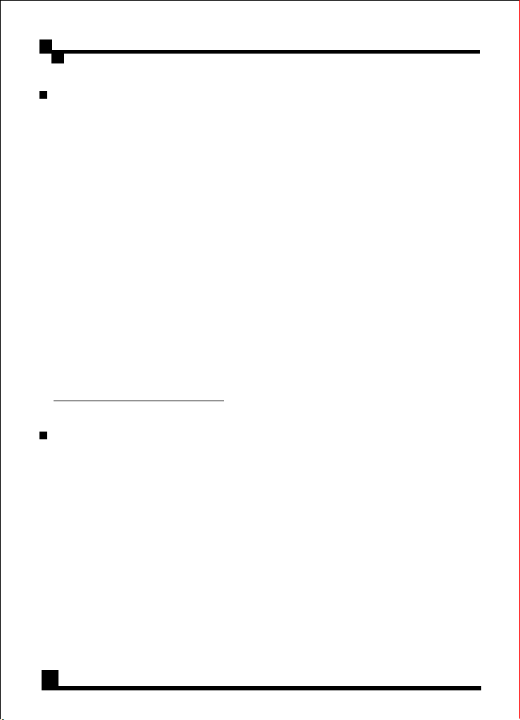
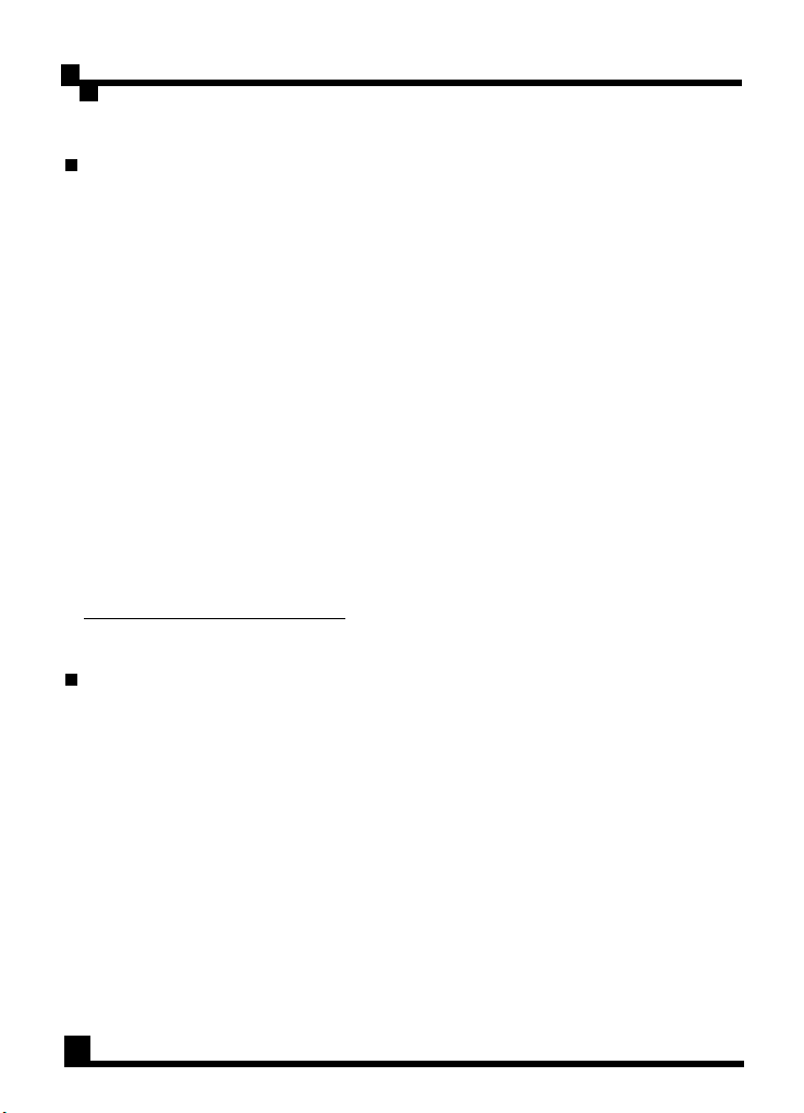
5.7 SATA Connector
+3.3V
COM
+5V
COM
+12V
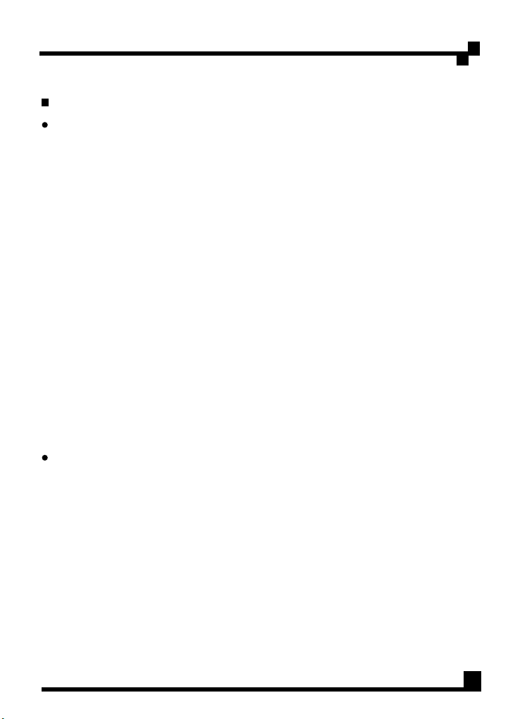
5.8 Peripheral Connector
+12V
COM
COM
+5V
Pin
1
2
3
4
Pin
1
2
3
Pin
1
2
3
4
5
Pin
1
2
3
4
Description
+12V
4
+12V
4
+12V
4
Description
+12V
4
+12V
4
+12V
4
Description
+3.3V
COM
+5V
COM
+12V
1
Description
+12V
1
COM
COM
+5V
Color
Yellow / Green Stripe
Yellow / Green Stripe
Yellow / Green Stripe
Black
Color
Yellow / Green Stripe
Yellow / Green Stripe
Yellow / Green Stripe
Color
Orange
Black
Red
Black
Yellow / Black Striple
Color
Yellow / Black Striple
Black
Black
Red
Pin
5
6
7
8
Pin
4
5
6
Description
COM
COM
COM
COMCOM
Description
COM
COM
COM
Color
Black
Black
Black
Black
Color
Black
Black
Black
5.9 Floppy Connector
Description
Pin
+12V
Pin 1
Pin 4
1
COM
2
COM
3
+5V
4
Yellow / Black Striple
1
Color
Black
Black
Red
6
Page 11
User Manual / English
6. Automatic Fan Speed Control
Exact CFM requirements vary by application and end-use environment, but 60~80
CFM is typical for the 120mm fan itself. For noise-sensitive applications, it is
recommended that a thermally sensitive fan speed control circuit be used to balance
system-level thermal and acoustic performance. This circuit typically senses the
temperature of an internal heat sink and/or incoming ambient air and adjusts the fan
speed as necessary to keep power supply and system component temperatures
within specifications. Please refer to the fan speed control drawing below.
Fan Vo ltage (V)
12
10
8
6
4
2
0
10%
Fan Voltage
Fan Speed
20%
30%
40%
50%
Load(%)
60%
70%
80%
Fan S peed( R.P.M )
100 %
90%
200 0
180 0
160 0
140 0
120 0
100 0
800
600
400
7
Page 12

Table des matières
Garantie
Consignes de Sécurité Importantes
1. Présentation
1.1 Introduction
1.2 Caractéristiques Clés
1.3 Descriptions des Modèles
2. Spécifications
2.1 Spécifications d'Entrée
2.2 Spécifications de sortie
2.3 Environnements
3. Installation
4. Dépannage
5. Description des connecteurs
5.1 Connecteur P1 (Carte mère) / 24 broches
-- -- -- -- -- -- -- -- -- ----------- -- -- -- -- -- -- -- -- -- -- -- -- -- -- -- -- -- -- ----------- -- -- -
-- -- -- -- -- -- -- -- -- ----------- -- -- -
-- -- -- -- -- -- -- -- -- ----------- -- -- -- -- -- -- -- -- -- -- -- -- -- -- -- -- -- -- ----
-- -- -- -- -- -- -- -- -- ----------- -- -- -- -- -- -- -- -- -- -- -- -- -- -- -- -- -- -- -
-- -- -- -- -- -- -- -- -- ----------- -- -- -- -- -- -- -- -- -- -- -- -
-- -- -- -- -- -- -- -- -- ----------- -- -- -- -- -- -- -- --
-- -- -- -- -- -- -- -- -- ----------- -- -- -- -- -- -- -- -- -- -- -- -- -- -- -- -- -- -- --
-- -- -- -- -- -- -- -- -- ----------- -- -- -- -- -- -- -- -- -- --
-- -- -- -- -- -- -- -- -- ----------- -- -- -- -- -- -- -- -- -- --
-- -- -- -- -- -- -- -- -- ----------- -- -- -- -- -- -- -- -- -- -- -- -- -- -- --
-- -- -- -- -- -- -- -- -- ----------- -- -- -- -- -- -- -- -- -- -- -- -- -- -- -- -- -- -- ------
-- -- -- -- -- -- -- -- -- ----------- -- -- -- -- -- -- -- -- -- -- -- -- -- -- -- -- -- -- -------
-- -- -- -- -- -- -- -- -- ----------- -- -- -- -- -- --
-- -- -- -- -- -- -- -- -- -
5.2 Connecteur P2,P3 (Alimentation +12V) / 4+4 broches
5.3 Connecteur (PCI-e) / 8 broches
5.4 Connecteur (PCI-e) / 6 broches
5.5 Connecteur (PCI-e) / 8 broches
5.6 Connecteur (PCI-e) / 6 broches
5.7 Connecteurs (SATA)
-- -- -- -- -- -- -- -- -- ----------- -- -- -- -- -- -- -- -- -- -- -- -- -
5.8 Connecteurs (Périphérique) / 4 broches
5.9 Connecteur (Lecteur de disquette)
-- -- -- -- -- -- -- -- -- ----------- -- -- -- -
-- -- -- -- -- -- -- -- -- ----------- -- -- -- -
-- -- -- -- -- -- -- -- -- ----------- -- -- --
-- -- -- -- -- -- -- -- -- ----------- -- -- -- -
-- -- -- -- -- -- -- -- -- -----
-- -- -- -- -- -- -- -- -- ----------- --
6. Contrôle de vitesse Ventilateur automatique
-- -- -- -- -- -- -
1
1
2
2
2
3
3
3
3
3
4
4
5
5
5
--
5
5
6
6
6
6
6
7
Page 13
Manuel de l'Utilisateur / Français
Garantie
Cooler Master garantit que cet appareil est est sans défaut en pièce et main
d'œuvre, et Cooler Master offre une garantie limitée de trois ans sur les
pièces pour l'alimentation livrée avec le boîtier à compter de la date d'achat.
Conservez soigneusement votre reçu.
Ce produit est conçu pour être utilisé sur ordinateur seulement. Le fait
d'utiliser ce produit dans toute autre application annulerait la garantie. Si
vous n'avez pas l'habitude d'installer des matériels informatiques, faites
appel à un professionnel.
La garantie est offerte pour l'appareil concernant des dommages se
produisant lors d'une utilisation normale. La garantie sera annulée s'il est
déterminé que l'appareil a été endommagé pour des raisons d'abus, de
modification, de négligence, d'alimentation avec un voltage non correct,
d'accidents de pollution d'air/eau et désastres naturels.
Cooler Master Co., Ltd.
9F., No. 786, Chung-Cheng Rd., Chung-Ho City, Taipei Hsien, Taiwan, R.O.C.
TEL: +886-2-3234-0050
FAX: +886-2-3234-0051
Http://www.coolermaster.com
Consignes de Sécurité Importantes
Pour assurer votre propre sécurité, observez les règles de base suivantes:
1. Eteignez et débranchez votre bloc d'alimentation de la prise de courant CA
du secteur avant de le nettoyer. N'utilisez pas de nettoyants liquides ou
d'aérosols. Utilisez un chiffon sec pour nettoyer la surface externe de
votre bloc d'alimentation.
2. N'installez pas ou n'utilisez pas votre ordinateur près d'un point d'eau.
3. Le bloc d'alimentation doit être alimenté par la source indiquée sur
l'étiquette des caractéristiques.
4. Ne projetez jamais de liquide d'aucune sorte sur le bloc d'alimentation.
5. Si le bloc d'alimentation ne fonctionne pas normalement, n'hésitez pas à
contacter notre service clientèle.
1
Page 14
Manuel de l'Utilisateur / Français
1. Présentation
1.1 Introduction
UCP—Ultimate Circuit Protection (Protection de Circuit Ultime)
L’alimentation est la source essentielle qui fait battre le cœur de votre PC. Cooler
Master reconnaît l’importance de la qualité du bloc d’alimentation (PSU) et a créé
une nouvelle ligne appelée UCP—Ultimate Circuit Protection. L’apparence, la
sensation, et la conception de cette nouvelle ligne sont complètement différentes;
des nouvelles fonctionnalités incluent un revêtement unique résistant aux rayures
en plus d’être certifié bon pour l’environnement. Une nouvelle structure interne
innovante, prévue pour être performante et durable, permet au PSU de fournir un
rendement de 87%—un nombre presque jamais entendu auparavant! Cooler Master
croit en la satisfaction de ses clients et défend ses produits. Une garantie de 5 ans
et un plan de protection ont été mis en place à l'égard des clients.
Le bloc d'alimentation est un composant clé fournissant tout le courant nécessaire
permettant de prendre en charge le fonctionnement du PC afin de maintenir une
stabilité et une fiabilité continue de l'ordinateur. Le bloc d'alimentation de Cooler
Master permet à votre PC de fonctionner mieux et plus efficacement, avec la
meilleure source d'alimentation pour votre PC. Il améliore aussi la fiabilité du
système en empêchant les anomalies principales d'alimentation dues aux pointes et
de surtensions. De plus, l'alimentation offre une parfaite protection à votre
système. RS-700-AAAA-A3 est conforme aux alimentations ATX 12V V2.3 et EPS
12V V2.92 power qui offrent plus de capacité d'alimentation pour l'utilisation du
processeur.
1.2 Caractéristiques Clés
1. Prend entièrement en charge le nouveau Intel ATX 12V V2.3
2. Conforme au dernier SSI EPS 12V V2.92
3. Fonctionnement super silencieux avec contrôleur de vitesse de ventilateur
intelligent
4. Connecteur Quad PCI-e satisfait les besoins des cartes graphiques haut de
gamme
5. Conception Green power pour répondre aux exigences “energy star” et “blue
angel” pour l'énergie et l'économie
6. Efficacité de plus de 87% à une opération de charge typique
7. Durée de vie : MTBF > 100,000 Heures
8. Protection: OVP / OCP / OTP / SCP / OPP / UVP
9. Correction de facteur d'alimentation active (PF > 0.9)
10. Une capacité d'alimentation réelle satisfait une exploitation de Système haut de
gamme
2
Page 15
Manuel de l'Utilisateur / Français
1.3 Descriptions des Modèles
RS-700-AAAA-A3: Alimentation PFC Active 700W
2. Spécifications
2.1 Spécifications d'Entrée
1. Type: ATX 12V V2.3 / SSI EPS 12V V2.92
2. Voltage: 90V ~ 264V (Plage Auto)
3. Courant : 10A @ 115Vac / 5A @ 230Vac
4. Fréquence : 47Hz ~ 63Hz
5. Un très bon signal d'alimentation: 100ms ~ 500ms
6. Temps de rétention: > 17ms
7. Efficacité (Charge): > 87%
8. Capacité de Sortie: 700W de façon continue
9. Capacité optimale: 840W
2.2 Spécifications de sortie
RS-700-AAAA-A3
100-240V~ 10-5A 60-50Hz
22A
133W
+5V
+12V1+12V2+12V3+12V
22A
624W
700W
19A19A19A19A
+3.3V
PUISSANCE
TOTAL
+5V
-12V
4
0.5A
6W
S
3A
15W
2.3 Environnements
1. Dimensions : 150 x 150 x 86 (mm)
2. Température de fonctionnement: 0 ~ 40 C
3. MTBF: > 100,000 Heures
4. EMC: CE / FCC / C-tick
5. Sécurité: UL / TUV / NEMKO / GOST
3
O
Page 16
Manuel de l'Utilisateur / Français
3. Installation
1. Eteignez à l'aide de l'interrupteur principal de l'alimentation et
débranchez le cordon d'alimentation.
2. Dévissez et ouvrez le panneau latéral du châssis.
3. Débranchez tous les connecteurs d'alimentation de la carte mère et des
périphériques tels que les ventilateurs de boîtier, disques durs, CD-ROM,
lecteurs de disquettes, etc.
4. Remplacez l'alimentation.
5. Branchez les connecteurs P1(24 broches) et P2,P3(Alimentation 4+4
broches) sur votre carte mère.
6. Branchez les autres connecteurs aux composants de votre système.
7. Vérifiez que tous les connecteurs sont branchés.
8. Fermez le châssis avec les vis.
9. Branchez le cordon d'alimentation au bloc d'alimentation et allumez à
l'aide de l'interrupteur principal.
4. Dépannage
Si vous ne pouvez pas allumer votre système après avoir installé le
bloc d'alimentation, suivez le guide de dépannage présenté ci-dessous:
1. Assurez-vous que l'alimentation principale est correctement allumée.
2. Vérifiez que les connecteurs P1 et P2 sont connectés correctement sur
la carte mère.
3. Si l'alimentation ne fonctionne pas correctement, veuillez contacter
notre service clientèle immédiatement.
4
Page 17
Manuel de l'Utilisateur / Français
5. Description des connecteurs
5.1 Connecteur P1 (Carte mère)
Pin1 Pin13
Broche
1
2
3
4
5
6
7
8
9
10
11
12
Description
+3.3V
+3.3V
COM
+5V
COM
+5V
COM
PWR_OK
+5V
SB
+12V
1
+12V
1
+3.3V
Couleur
Orange
Orange
Noir
Rouge
Noir
Rouge
Noir
Gris
Violet
Jaune/Noir
Jaune/Noir
Orange
Broche
5.2 Connecteur P2,P3 (Alimentation +12V) / 4+4 broches
Pin1 Pin5
Broche
1
2
3
4
Description
COM
COM
COM
COM
Couleur
Noir
Noir
Noir
Noir
Broche
13
14
15
16
17
18
19
20
21
22
23
24
5
6
7
8
Description
+3.3V
+3.3V
-12V
COM
PS_ON
COM
COM
COM
+5V
+5V
+5V
COM
Description
+12V
2
+12V
2
+12V
2
+12V
2
s
Couleur
Orange
Marron
Bleu
Noir
Vert
Noir
Noir
Noir
Rouge
Rouge
Rouge
Noir
Couleur
Jaune
Jaune
Jaune
Jaune
5.3 Connecteur (PCI-e) / 8 broches
Pin1 Pin5
Broche
1
2
3
4
Description
+12V
3
+12V
3
+12V
3
COM
Couleur
Jaune/Bleu
Jaune/Bleu
Jaune/Bleu
Noir
5.4 Connecteur (PCI-e) / 6 broches
1
2
3
Description
+12V
3
+12V
3
+12V
3
CouleurBroche
Jaune/Bleu
Jaune/Bleu
Jaune/Bleu
Pin1 Pin4
5
Broche
5
6
7
8
Broche
4
5
6
Description
COM
COM
COM
COM
Description
COM
COM
COM
Couleur
Noir
Noir
Noir
Noir
Couleur
Noir
Noir
Noir
Page 18
Manuel de l'Utilisateur / Français
5.5 Connecteur (PCI-e) / 8 broches
Pin1 Pin5
Broche
5.6 Connecteur (PCI-e) / 6 broches
Pin1 Pin4
5.7 Connecteurs (SATA)
+3.3V
COM
+5V
COM
+12V
Broche
5.8 Connecteurs (Périphérique) /4 broches
+12V
COM
COM
+5V
Broche
1
2
3
4
1
2
3
1
2
3
4
5
1
2
3
4
Description
+12V
4
+12V
4
+12V
4
COM
Description
+12V
4
+12V
4
+12V
4
Description
+3.3V
COM
+5V
COM
+12V
1
Description
+12V
1
COM
COM
+5V
Couleur
Jaune/Vert
Jaune/Vert
Jaune/Vert
Noir
CouleurBroche
Jaune/Vert
Jaune/Vert
Jaune/Vert
Couleur
Orange
Noir
Rouge
Noir
Jaune/Noir
Couleur
Jaune/Noir
Noir
Noir
Rouge
Broche
5
6
7
8
Broche
4
5
6
Description
COM
COM
COM
COM
Description
COM
COM
COM
Couleur
Noir
Noir
Noir
Noir
Couleur
Noir
Noir
Noir
5.9 Connecteur (Lecteur de disquette)
1
2
3
4
Description
+12V
1
COM
COM
+5V
Couleur
Jaune/Noir
Noir
Noir
Rouge
Pin 1
Broche
Pin 4
6
Page 19
Manuel de l'Utilisateur / Français
6. Contrôle de vitesse Ventilateur automatique
Les exigences CFM varient selon les applications et l'environnement d'utilisation finale,
mais le 60~80 CFM est typique pour le ventilateur 120mm. Pour des applications
sensibles au bruit, il est recommandé qu'un circuit de contrôle de vitesse du
ventilateur thermo-sensible soit utilisé pour équilibrer les performances accoustiques
et thermiques au niveau du système. Ce circuit détecte généralement la température
d'un dissipateur de chaleur et/ou de l'air ambiant entrant et ajuste la vitesse du
ventilateur si nécessaire pour conserver les températures de l'alimentation et des
composants du système au niveau requis par les spécifications. Veuillez vous reporter
à l'illustration du contrôle de vitesse du ventilateur donnée ci-dessous.
Fan Vo ltage (V)
12
10
8
6
4
2
0
10%
Fan Voltage
Fan Speed
20%
30%
40%
50%
Load(%)
60%
70%
80%
Fan S peed( R.P.M )
100 %
90%
200 0
180 0
160 0
140 0
120 0
100 0
800
600
400
7
Page 20

Inhalt
Garantie
Wichtige Sicherheitshinweise
1. Übersicht
1.1 Einführung
1.2 Leistungsmerkmale
1.3 Modellbeschreibung
2. Spezifikationen
2.1 Eingang
2.2 Ausgang
2.3 Umgebungsbedingungen
3. Installation
4. Fehlerbehebung
5. Anschlüsse
5.1 P1-Anschlüss (Motherboard) / 24-polig
5.2 P2,P3-Anschlüss (+12V Strom) / 4+4-polig
5.3 Anschlüss (PCI-e) / 8-polig
5.4 Anschlüss (PCI-e) / 6-polig
5.5 Anschlüss (PCI-e) / 8-polig
5.6 Anschlüss (PCI-e) / 6-polig
5.7 Anschlüsse (SATA)
5.8 Anschlüsse (Peripherie)
5.9 Anschlüss (Floppy)
6. Automatische Steuerung der Ventilatorgeschwindigkeit
-- -- -- -- -- -- -- -- -- ----------- -- -- -- -- -- -- -- -- -- -- -- -- -- -- -- -- -- -- ----------- -- -- -
-- -- -- -- -- -- -- -- -- ----------- -- -- -- -- -- -- -- -
-- -- -- -- -- -- -- -- -- ----------- -- -- -- -- -- -- -- -- -- -- -- -- -- -- -- -- -- -- ----------- -
-- -- -- -- -- -- -- -- -- ----------- -- -- -- -- -- -- -- -- -- -- -- -- -- -- -- -- -- -- -----
-- -- -- -- -- -- -- -- -- ----------- -- -- -- -- -- -- -- -- -- -- -- -- -- -- --
-- -- -- -- -- -- -- -- -- ----------- -- -- -- -- -- -- -- -- -- -- -- -- -- -- -
-- -- -- -- -- -- -- -- -- ----------- -- -- -- -- -- -- -- -- -- -- -- -- -- -- -- -- -- -- ---
-- -- -- -- -- -- -- -- -- ----------- -- -- -- -- -- -- -- -- -- -- -- -- -- -- -- -- -- -- ----------
-- -- -- -- -- -- -- -- -- ----------- -- -- -- -- -- -- -- -- -- -- -- -- -- -- -- -- -- -----------
-- -- -- -- -- -- -- -- -- ----------- -- -- -- -- -- -- -- -- -- -- --
-- -- -- -- -- -- -- -- -- ----------- -- -- -- -- -- -- -- -- -- -- -- -- -- -- -- -- -- -- ---------
-- -- -- -- -- -- -- -- -- ----------- -- -- -- -- -- -- -- -- -- -- -- -- -- -- -- -- -- -- -
-- -- -- -- -- -- -- -- -- ----------- -- -- -- -- -- -- -- -- -- -- -- -- -- -- -- -- -- -- ---------
-- -- -- -- -- -- -- -- -- -----------
-- -- -- -- -- -- -- -- -- ----
-- -- -- -- -- -- -- -- -- ----------- -- -- -- -- -- -- -- -- -
-- -- -- -- -- -- -- -- -- ----------- -- -- -- -- -- -- -- -- -
-- -- -- -- -- -- -- -- -- ----------- -- -- -- -- -- -- -- -- --
-- -- -- -- -- -- -- -- -- ----------- -- -- -- -- -- -- -- -- -
-- -- -- -- -- -- -- -- -- ----------- -- -- -- -- -- -- -- -- -- -- -- -- -- -- -
-- -- -- -- -- -- -- -- -- ----------- -- -- -- -- -- -- -- -- -- -- --
-- -- -- -- -- -- -- -- -- ----------- -- -- -- -- -- -- -- -- -- -- -- -- -- --
-- --
1
1
2
2
2
3
3
3
3
3
4
4
5
5
5
5
5
6
6
6
6
6
7
Page 21
User Manual / Deutsch
Garantie
Cooler Master garantiert, dass dieses Gerät frei von Material- und
Herstellungsfehlern ist. Cooler Master bietet beschränkt auf die Hardware
beginnend mit dem Kaufdatum eine Garantie für das Netzteil mit
dem Gehäuse. Bewahren Sie die Quittung als Kaufbeleg sorgfältig auf.
Dieses Produkt ist nur für die Benutzung mit einem Computer vorgesehen.
Die Verwendung dieses Produkts in einem anderen Gerät führt zum Verlust
der Garantieansprüche. Wenn Sie sich bei der Installation der ComputerHardware unsicher sind, wenden Sie sich an einen Fachmann.
Die vorliegende Garantie ist nur bei normaler Benutzung des Produkts
gültig. Die Garantie ist ungültig, wenn festgestellt werden sollte, dass das
Gerät aufgrund zweckentfremdeter Benutzung, fehlerhafter Benutzung,
Manipulation des Geräts, unvorsichtiger Handhabung, Anschlusses an
ungeeignete Stromquellen, Unfällen mit Luft-/Wasserverschmutzung und in
der Folge von Naturkatastrophen beschädigt wurde.
Cooler Master Co., Ltd.
9F., No. 786, Chung-Cheng Rd., Chung-Ho City, Taipei Hsien, Taiwan,
R.O.C.
TEL: +886-2-3234-0050
FAX: +886-2-3234-0051
Http://www.coolermaster.com
5 jahres
Wichtige Sicherheitshinweise
Für Ihre eigene Sicherheit ist es wichtig, dass Sie die folgenden
Grundregeln beachten:
1. Schalten Sie die PSU (Stromversorgungseinheit) vor dem Reinigen
aus und trennen sie vom Stromnetz. Verwenden Sie keine
Reinigungsflüssigkeiten oder -sprays. Reinigen Sie das Gehäuse der
PSU von außen mit einem trockenen Tuch.
2. Das Computersystem darf nicht in der Nähe von Wasser aufgestellt
oder betrieben werden.
3. Die Stromquelle, mit der die PSU betrieben wird, muss mit den auf
dem Etikett angegebenen Werten übereinstimmen.
4. Achten Sie darauf, dass keine Flüssigkeiten auf der PSU auskippen.
5. Wenden Sie sich an das Servicezentrum, wenn die PSU
Funktionsstörungen aufweist.
1
Page 22
User Manual / Deutsch
1. Übersicht
1.1 Einführung
UCP—Ultimate Circuit Protection (Ultimative Stromkreis und Schutz)
Das Netzteil bestimmt im Wesentlichen der Herzschlag Ihres Computers. Cooler
Master hat die Wichtigkeit einer hochwertigen PSU erkannt und ein neues
Spitzenprodukt mit dem Namen UCP—Ultimate Circuit Protection. Das Aussehen
und das Design dieser neuen Linie ist ganz neu und anders. Neue Merkmale sind
eine einzigartig kratzfeste Beschichtung sowie ein Öko-Zertifikat. Mit dem
innovativen internen Aufbau erreicht diese leistungsstarke und stabile PSU eine
Effizienz von 87% - eine fast beispiellose Zahl! Cooler Masters Ziel ist
Kundenzufriedenheit, und das Unternehmen steht hinter seinen Produkten. Mit
Hinblick auf den Kunden wurde ein 5-jähriger Garantie- und Schutzplan
entwickelt.
Das Netzteil ist die Schlüsselkomponente für den Betrieb des Computers, indem
es alle Elemente mit dem erforderlichen Strom versorgt und für eine
gleichbleibende Stabilität und Zuverlässigkeit des Computersystems sorgt. Mit
dem Netzteil von Cooler Master kann Ihr PC besser und effizienter arbeiten. Es
ist die bessere Stromquelle, weil es in den PC eingebaut wird. Es verbessert
außerdem die Zuverlässigkeit des Systems, indem es Spannungsspitzen und
unterbrechungen des Stromnetzes ausgleicht. Das Netzteil bietet Ihrem System
zusätzlich den besten Schutz.Das RS-700-AAAA-A3 ist mit den Netzteilen ATX
12V V2.3 und EPS 12V V2.92 konform, die noch mehr Energiekapazitäten für den
CPU-Gebrauch bereitstellen.
1.2 Leistungsmerkmale
1. Volle Unterstützung des neuesten Intel ATX 12V V2.3
2. Konformität mit dem neuesten SSI EPS 12V V2.92
3. Extrem leiser Betrieb mit intelligenter Lüftergeschwindigkeits Steuerung
4. Quad PCI-e-Anschlüss erfüllt die Erfordernisse für anspruchsvolle
Grafikkarten
5. "Green Power"-Design, das den Anforderungen gemäß “energy
star” und “blue angel” zum Sparen von Energie und Kosten Entspricht
6. Mehr als 87% an Effizienz bei typischem Ladebetrieb
7. Betriebsdauer: MTBF > 100,000 Stunden
Schutz: OVP / OCP / OTP / SCP / OPP / UVP
8.
9. Aktive Blindstromkompensation (PF > 0.9)
10. Echtstromkapazität erfüllt die Bedürfnisse bei anspruchsvollem
Systembetrieb
2
Page 23
User Manual / Deutsch
1.3 Modellbeschreibung
RS-700-AAAA-A3: 700W Aktives PFC-Netzteil
2. Spezifikationen
2.1 Eingang
1. Typ: ATX 12V V2.3 / SSI EPS 12V V2.92
2. Spannung: 90V ~ 264V (autom. Bereich)
3. Stromstärke: 10A bei 115Vac / 5A bei 230Vac
4. Frequenz: 47Hz ~ 63Hz
5. Strom-Gut-Signal: 100ms ~ 500ms
6. Haltezeit: > 17ms
7. Effizienz (Last) : > 87%
8. Ausgangskapazität: 700W kontinuierlich
9. Spitzenleistung: 840W
2.2 Ausgang
RS-700-AAAA-A3
AC-EINGANG
DC-AUSGANG
GESAMTMENGE
LEISTUNG
+3.3V
22A
133W
100-240V~ 10-5A 60-50Hz
+5V
+12V1+12V2+12V3+12V
22A
624W
700W
+5V
-12V
4
0.5A
19A19A19A19A
6W
S
3A
15W
2.3 Umgebungsbedingungen
1. Abmessungen: 150 x 150 x 86 (mm)
2. Betriebstemperatur: 0 ~ 40°C
3. MTBF: > 100,000 Stunden
4. EMC: CE / FCC / C-tick
5. Sicherheit: UL / TUV / NEMKO / GOST
3
Page 24
User Manual / Deutsch
3. Installation
1. Schalten Sie den Hauptschalter des Netzteils aus und trennen das
System vom Stromnetz.
2. Lösen Sie die Schrauben des Chassis und nehmen die Seitenwand des
Gehäuses ab.
3. Trennen Sie alle Stromstecker vom Motherboard und von allen
Peripheriegeräten wie den Gehäuselüftern, Festplatten, CD-ROMLaufwerken, Diskettenlaufwerken usw. ab.
4. Wechseln Sie das Netzteil aus.
5. Schließen Sie die Stecker P1(24-polig) und P2,P3(CPU 4+4-polig) das
Motherboard an.
6. Schließen Sie die anderen Stecker an die Systemkomponenten an.
7. Überprüfen Sie noch einmal alle Kabelverbindungen.
8. Schließen Sie das Computergehäuse und schrauben es fest.
9. Schließen Sie das System an das Stromnetz an und schalten es am
Hauptschalter ein.
4. Fehlerbehebung
Wenn Sie das System nach der Installation des Netzteils nicht
einschalten können, führen Sie die unten aufgeführten Prüfschritte
durch:
1. Stellen Sie sicher, dass der Hauptschalter richtig eingeschaltet ist.
2. Überprüfen Sie, ob die Stecker P1 und P2 richtig am Motherboard
angeschlossen sind.
3. Wenn das Netzteil nicht einwandfrei funktioniert, wenden Sie sich
umgehend an unser Servicecenter.
4
Page 25
User Manual / Deutsch
5. Anschlüsse
5.1 P1-Anschlüss (Motherboard) / 24-polig
Pin1 Pin13
Pin Pin
+3.3V
1
2
3
4
5
6
7
8
9
10
11
12
+3.3V
COM
+5V
COM
+5V
COM
PWR_OK
+5V
SB
+12V
+12V
+3.3V
1
1
Farbe
Orange
Orange
Schwarz
Rot
Schwarz
Rot
Schwarz
Grau
Lila
Gelb/Schwarz
Gelb/Schwarz
Orange
Beschreibung
5.2 P2,P3-Anschlüss (+12V Strom) / 4+4-polig
Pin1 Pin5
Beschreibung
Pin
1
2
3
4
COM
COM
COM
COM
Farbe
Schwarz
Schwarz
Schwarz
Schwarz
Pin
13
14
15
16
17
18
19
20
21
22
23
24
Beschreibung
5
6
7
8
Beschreibung
+3.3V
+12V
+12V
+12V
+12V
+3.3V
-12V
COM
PS_ON
COM
COM
COM
+5V
+5V
+5V
COM
2
2
2
2
Farbe
Orange
Braun
s
Blau
Schwarz
Grün
Schwarz
Schwarz
Schwarz
Rot
Rot
Rot
Schwarz
Farbe
Gelb
Gelb
Gelb
Gelb
5.3 Anschlüss (PCI-e) / 8-polig
Pin1 Pin5
Beschreibung
Pin
1
2
3
4
+12V
+12V
+12V
COM
3
3
3
Farbe
Gelb/Blau
Gelb/Blau
Gelb/Blau
Schwarz
5.4 Anschlüss (PCI-e) / 6-polig
Pin1 Pin4
Beschreibung
Pin
1
2
3
+12V
+12V
+12V
3
3
3
Farbe
Gelb/Blau
Gelb/Blau
Gelb/Blau
5
Beschreibung
Pin
5
6
7
8
Beschreibung
Pin
4
5
6
COM
COM
COM
COM
COM
COM
COM
Farbe
Schwarz
Schwarz
Schwarz
Schwarz
Farbe
Schwarz
Schwarz
Schwarz
Page 26
User Manual / Deutsch
5.5 Anschlüss (PCI-e) / 8-polig
Pin1 Pin5
5.6 Anschlüss (PCI-e) / 6-polig
Pin1 Pin4
5.7 Anschlüsse (SATA)
+3.3V
COM
+5V
COM
+12V
5.8 Anschlüsse (Peripherie)
+12V
COM
COM
+5V
Beschreibung
Pin
1
2
3
4
Beschreibung
Pin
1
2
3
Beschreibung
Pin
1
2
3
4
5
Beschreibung
Pin
1
2
3
4
+12V
+12V
+12V
COM
+12V
+12V
+12V
+3.3V
COM
COM
+12V
+12V
COM
COM
+5V
4
4
4
4
4
4
1
1
Farbe
Gelb/Groen
Gelb/Groen
Gelb/Groen
Gelb/Groen
Farbe
Gelb/Groen
Gelb/Groen
Gelb/Groen
Farbe
Orange
Schwarz
Schwarz
Gelb/Schwarz
Farbe
Gelb/Schwarz
Schwarz
Schwarz
Rot+5V
Rot
Beschreibung
Pin
5
6
7
8
Beschreibung
Pin
4
5
6
COM
COM
COM
COM
COM
COM
COM
Farbe
Schwarz
Schwarz
Schwarz
Schwarz
Farbe
Schwarz
Schwarz
Schwarz
5.9 Anschlüss (Floppy)
Beschreibung
Pin 1
Pin 4
Pin
+12V
1
2
3
4
COM
COM
+5V
1
Farbe
Gelb/Schwarz
Schwarz
Schwarz
Rot
6
Page 27

User Manual / Deutsch
6. Automatische Steuerung der
Ventilatorgeschwindigkeit
Genaue CFM-Anforderungen unterscheiden sich von Anwendung zu Anwendung
sowie vom Endbenutzerumfeld, aber 60~80 CFM ist typisch für den 120mmVentilator. Bei geräuschsensiblen Anwendungen sollte eine temperatursensible
Steuerung der Ventilatorgeschwindigkeit verwendet werden, um die thermale und
akkustische Leistung des Systems abzustimmen. Dieser Kreislauf erkennt
normalerweise die Temperatur einer internen Hitzesenke und/oder
Hereinkommender Luft und passt die Ventilatorgeschwindigkeit an, um die
Stromversorgung und die Temperaturen der Systemkomponenten einzustellen.
Sehen Sie bitte die Abbildung für die Steuerung der Ventilatorgeschwindigkeit.
Fan Vo ltage (V)
12
10
8
6
4
2
0
10%
Fan Voltage
Fan Speed
20%
30%
40%
50%
60%
Load(%)
70%
80%
Fan S peed( R.P.M )
100 %
90%
200 0
180 0
160 0
140 0
120 0
100 0
800
600
400
7
Page 28

Indice
Garanzia
Importanti misure di sicurezza
1. Panoramica
1.1 Introduzione
1.2 Funzioni chiave
1.3 Descrizioni del modello
2. Specifiche
2.1 Specifiche ingresso
2.2 Specifiche uscita
2.3 Ambienti
3. Installazione
4. Individuazione guasti
5. Descrizione dei connettori
5.1 P1 Connettore (Sched madre) / pin 24
5.2 P2,P3 Connettore (alimentazione +12V) / pin 4+4
5.3 Connettore (PCI-e) / pin 8
5.4 Connettore (PCI-e) / pin 6
5.5 Connettore (PCI-e) / pin 8
5.6 Connettore (PCI-e) / pin 6
5.7 Connettori (SATA)
5.8 Connettori (Peripheral) / pin 4
5.9 Connettore (Floppy)
6. Controllo automatico della ventola
-- -- -- -- -- -- -- -- -- ----------- -- -- -- -- -- -- -- -- -- -- -- -- -- -- -- -- -- -- ----------- -- -- --
-- -- -- -- -- -- -- -- -- ----------- -- -- -- -- -- -- -- -- --
-- -- -- -- -- -- -- -- -- ----------- -- -- -- -- -- -- -- -- -- -- -- -- -- -- -- -- -- -- ---------
-- -- -- -- -- -- -- -- -- ----------- -- -- -- -- -- -- -- -- -- -- -- -- -- -- -- -- -- -- ---
-- -- -- -- -- -- -- -- -- ----------- -- -- -- -- -- -- -- -- -- -- -- -- -- -- -- -- -- -
-- -- -- -- -- -- -- -- -- ----------- -- -- -- -- -- -- -- -- -- -- -- --
-- -- -- -- -- -- -- -- -- ----------- -- -- -- -- -- -- -- -- -- -- -- -- -- -- -- -- -- -- -----------
-- -- -- -- -- -- -- -- -- ----------- -- -- -- -- -- -- -- -- -- -- -- -- -- -- --
-- -- -- -- -- -- -- -- -- ----------- -- -- -- -- -- -- -- -- -- -- -- -- -- -- -- -- -
-- -- -- -- -- -- -- -- -- ----------- -- -- -- -- -- -- -- -- -- -- -- -- -- -- -- -- -- -- --------
-- -- -- -- -- -- -- -- -- ----------- -- -- -- -- -- -- -- -- -- -- -- -- -- -- -- -- -- -- -------
-- -- -- -- -- -- -- -- -- ----------- -- -- -- -- -- -- -- -- -- -- -- -- -- -- -
-- -- -- -- -- -- -- -- -- ----------- -- -- -- -- -- -- -- -- -- -- --
-- -- -- -- -- -- -- -- -- -----------
-- -- -- -- -- -- -- -- -- ----------- -- -- -- -- -- -- -- -- --
-- -- -- -- -- -- -- -- -- ----------- -- -- -- -- -- -- -- -- --
-- -- -- -- -- -- -- -- -- ----------- -- -- -- -- -- -- -- -- -
-- -- -- -- -- -- -- -- -- ----------- -- -- -- -- -- -- -- -- -
-- -- -- -- -- -- -- -- -- ----------- -- -- -- -- -- -- -- -- -- -- -- -- -- -- --
-- -- -- -- -- -- -- -- -- ----------- -- -- -- -- -- --
-- -- -- -- -- -- -- -- -- ----------- -- -- -- -- -- -- -- -- -- -- -- -- -- -
-- -- -- -- -- -- -- -- -- ----------- -- -- -- -
-- -- -- -- -- --
1
1
2
2
2
2
3
3
3
3
4
4
5
5
5
5
5
6
6
6
6
6
7
Page 29

User Manual / Italiano
Garanzia
Cooler Master garantisce che il dispositivo in oggetto non presenta difetti di
materiale e lavorazione, inoltre Cooler Master fornisce una garanzia sul
prodotto hardware della durata di 5 anni per l'alimentazione a seconda del
caso a decorrere dalla data d'acquisto. Conservare la relativa ricevuta in un
luogo sicuro.
Questo prodotto è stato progettato per il solo utilizzo del computer. L'utilizzo
del dispositivo in oggetto in qualsiasi altra applicazione annullerà la validità
della garanzia. Qualora non si abbia familiarità con l'installazione hardware
del computer, richiedere assistenza professionale.
La garanzia copre i danni causati da un regolare utilizzo del dispositivo. La
garanzia sarà ritenuta nulla qualora si determini che il dispositivo è
danneggiato per uso scorretto, alterazione, uso improprio, negligenza,
alimentazione della tensione inappropriata, incidenti dovuti ad inquinamento
aria/acqua e disastri naturali.
Cooler Master Co., Ltd.
9F., No. 786, Chung-Cheng Rd., Chung-Ho City, Taipei Hsien, Taiwan, R.O.C.
TEL: +886-2-3234-0050
FAX: +886-2-3234-0051
Http://www.coolermaster.com
Importanti misure di sicurezza
Per garantire la propria sicurezza, osservare le seguenti regole
fondamentali:
1. Spegnere e staccare il PSU dalla presa AC commerciale prima di
eseguire la pulizia. Non utilizzare detergenti liquidi o spray. Utilizzare
un panno asciutto per pulire la superficie esterna del PSU.
2. Non installare o azionare il sistema di elaboratori vicino l'acqua.
3. Il PSU deve essere alimentato dalla sorgente indicata sull'etichetta di
prestazione.
4. Fare attenzione a non versare alcun tipo di liquido sul PSU.
5. Se il PSU non funziona regolarmente, contattare il nostro centro di
assistenza.
1
Page 30

User Manual / Italiano
1. Panoramica
1.1 Introduzione
UCP—Ultimate Circuit Protection (Protezione Circuito Definitiva)
L'alimentatore è essenzialmente il battito del cuore del PC. Cooler Master
riconosce l'importanza di utilizzare un alimentatore di qualità e ha creato una
nuova linea di fascia alta chiamata UCP, owero Ultimate Circuit Protection.
L'aspetto e il design di questa nuova linea sono completamente differenti. Tra le
funzionalità aggiuntive vi sono un rivestimento antigraffio unico e una
certificazione di rispetto dell'ambiente. Una innovativa struttura interna
costruita per consentire prestazioni e durabilità consente all'alimentatore di
fornire un'efficienza dell'87%. Mai sentita un'efficienza di questo livello! Cooler
Master è sempre attenta alla soddisfazione del cliente e tenta di raggiungere
questo risultato in tutti i suoi prodotti. Il suo piano di protezione e garanzia di 5
anni è stato sviluppato tenendo a mente quelle che sono le esigenze del cliente.
L'alimentazione è la chiave fondamentale per soddisfare tutte le esigenze
elettriche che supportano il funzionamento del PC al fine di garantire affidabilità
e stabilità continua del sistema di elaboratori. L'alimentazione Cooler Master
farà funzionare il vostro PC meglio e in modo più efficiente grazie anche al
migliore alimentatore in dotazione con il PC. Anche l'affidabilità del sistema
risulta ottimizzata, ciò impedisce un'alimentazione anomala di rete dovuta a
picchi e sovratensione. Inoltre l'alimentazione fornisce al vostro sistema una
protezione assoluta. RS-700-AAAA-A3 si adatta all'unità di alimentazione ATX
12V V2.3 e EPS 12V V2.92, con maggiore capacità di corrente per la CPU.
1.2 Funzioni chiave
1. Supporta completamente la più recente V2.3 di Intel ATX 12V
2. Conforme ai più recenti SSI per EPS 12V V2.92
3. Funzionamento supersilenzioso con controller intelligente della Velocità della
ventola
4. Il connettore Quad PCI-e soddisfa i requisiti della scheda grafica
5. Realizzazione Green Power per soddisfare i requisiti ”energy star" e "blue
angel" per risparmiare energia e denaro
6. Più dell'87% di efficienza nella tipica operazione di carico
7. Durata attesa: MTBF > 100,000 ore
8. Protezione: OVP / OCP / OPP / SCP / UVP / OTP
9. Correzione del fattore di potenza attiva (PF > 0.9)
10.La capacità di potenza attiva soddisfa il sistema high-end
1.3 Descrizioni del modello
RS-700-AAAA-A3: alimentazione PFC attiva 700W
2
Page 31

User Manual / Italiano
2. Specifiche
2.1 Specifiche ingresso
1. Tipo: ATX V2.3 / SSI EPS 12V V2.92
2. ensione: 90V ~ 264V (intervallo automatico)
3. Corrente: 10A @ 115Vac / 5A @ 230Vac
4. Frequenza: 47Hz ~ 63Hz
5. Segnale alimentazione corretta: 100ms ~ 500ms
6. Durata: > 17ms
7. Efficienza (carico): > 87%
8. Potenza di uscita: 700W continua
9. Capacità di picco: 840W
2.2 Specifiche uscita
RS-700-AAAA-A3
NGRESSO AC
USCITA DC
POTENZA TOTALE
+3.3V
22A
133W
100-240V~ 10-5A 60-50Hz
+5V
+12V1+12V2+12V3+12V
22A
624W
700W
+5V
-12V
4
0.5A
19A19A19A19A
6W
S
3A
15W
2.3 Ambienti
1. Dimensioni: 150 x 150 x 86 (mm)
2. Temperatura d'esercizio: da 0 a 40°C
3. MTBF: > 100,000 ore
4. EMC: CE / FCC / C-tick
5. Sicurezza: UL / TUV / NEMKO / GOST
3
Page 32

User Manual / Italiano
3. Installazione
1. Spegnere l'interruttore principale dell'alimentazione e scollegare il
cordone di alimentazione.
2. Svitare e aprire il pannello laterale del telaio.
3. Scollegare tutti i connettori elettrici dalla scheda madre e dai dispositivi
periferici quali ventole, dischi fissi, CD-ROM, dischi floppy, ecc.
4. Sostituire l'alimentazione.
5. Collegare i connettori P1(Pin 24) e P2,P3(CPU Pin 4+4) alla scheda
madre.
6. Collegare gli altri connettori ai componenti del sistema.
7. Verificare che i connettori siano ben fissati.
8. Chiudere il coperchio con le viti.
9. Inserire il cavo di alimentazione nella presa di rete a accendere
l'interruttore principale.
4. Individuazione guasti
Se è impossibile accendere il sistema dopo avere collegato l'alimentazione,
consultare la tabella di individuazione dei guasti elencata sotto.
1. Assicurarsi che l'almentaizone sia inserita in modo corretto.
2. Assicurarsi che i9 connettori P1 e P2 siano connessi in modo corretto
sulla scheda madre.
3. Se l'alimentazione non funziona in modo corretto, rivolgersi
immediatamente al centro di assistenza.
4
Page 33

User Manual / Italiano
5. Descrizione dei connettori
5.1 P1 Connettore (Sched madre) / pin 24
13
14
15
16
17
18
19
20
21
22
23
24
Pin
5
6
7
8
Descrizione
+3.3V
+3.3V
s
-12V
COM
PS_ON
COM
COM
COM
+5V
+5V
+5V
COM
Descrizione
+12V
2
+12V
2
+12V
2
+12V
2
Pin1 Pin13
Pin Pin
+3.3V
1
2
+3.3V
3
4
5
6
7
8
9
10
11
12
COM
+5V
COM
+5V
COM
PWR_OK
+5V
SB
+12V
1
+12V
1
+3.3V
Colore
Arancione
Arancione
Nero
Rosso
Nero
Rosso
Nero
Grigio
Viola
Giallo / Nero
Giallo / Nero
Arancione
Descrizione
5.2 P2,P3 Connettore (alimentazione +12V) / pin 4+4
Pin1 Pin5
Pin
1
2
3
4
Descrizione
COM
COM
COM
COM
Colore
Nero
Nero
Nero
Nero
Colore
Arancione
Marrone
Blu
Nero
Verde
Nero
Nero
Nero
Rosso
Rosso
Rosso
Nero
Colore
Giallo
Giallo
Giallo
Giallo
5.3 Connettore (PCI-e) / pin 8
Pin1 Pin5
Pin
1
2
3
4
Descrizione
+12V
3
+12V
3
+12V
3
COM
5.4 Connettore (PCI-e) / pin 6
Pin1 Pin4
Pin
1
2
3
Descrizione
+12V
3
+12V
3
+12V
3
5
Coloer
Giallo / Blu
Giallo / Blu
Giallo / Blu
Nero
Coloer
Giallo / Blu
Giallo / Blu
Giallo / Blu
Pin
5
6
7
8
Pin
4
5
6
Descrizione
COM
COM
COM
COM
Descrizione
COM
COM
COM
Coloer
Nero
Nero
Nero
Nero
Coloer
Nero
Nero
Nero
Page 34

User Manual / Italiano
5.5 Connettore (PCI-e) / pin 8
Pin1 Pin5
5.6 Connettore (PCI-e) / pin 6
Pin1 Pin4
5.7 Connettori (SATA)
+3.3V
COM
+5V
COM
+12V
5.8 Connettori (Peripheral)
+12V
COM
COM
+5V
Pin
1
2
3
4
Pin
1
2
3
Pin
1
2
3
4
5
Pin
1
2
3
4
Descrizione
+12V
4
+12V
4
+12V
4
COM
Descrizione
+12V
4
+12V
4
+12V
4
Descrizione
+3.3V
COM
+5V
COM
+12V
1
Descrizione
+12V
1
COM
COM
+5V
Coloer
Giallo / Verde
Giallo / Verde
Giallo / Verde
Coloer
Giallo / Verde
Giallo / Verde
Giallo / Verde
Coloer
Arancione
Rosso
Giallo / Nero
Colore
Giallo / Nero
Rosso
Nero
Nero
Nero
Nero
Nero
Pin
5
6
7
8
Pin
4
5
6
Descrizione
COM
COM
COM
COM
Descrizione
COM
COM
COM
Coloer
Nero
Nero
Nero
Nero
Coloer
Nero
Nero
Nero
5.9 Connettore (Floppy)
Descrizione
Pin 1
Pin 4
Pin
+12V
1
2
3
1
COM
COM
4
Colore
Giallo / Nero
Nero
Nero
Rosso+5V
6
Page 35

User Manual / Italiano
6. Controllo automatico della ventola
I requisiti relativi al volume di aria variano in relaziona al tipo di applicazione e
all'ambiente di utilizzo, per una ventola da 120 mm il valore tipico è pari a 60~80
CFM. Per applicazioni sensibili ai rumori, si raccomanda l'utilizzo di un circuito per il
controllo della ventola sensibile alla temperatura da utilizzare per equilibrare le
prestazioni acustiche e termiche del sistema. Questo circuito rileva la temperatura
del dissipatore di calore e/o dell'aria in ingresso e regola la velocità della ventola in
modo da tenere la temperatura dell'alimentatore e dei componenti del sistema entro
le specifiche. Consultare l'illustrazione relativa al controllo di velocità della ventola
riportata sotto.
Fan Vo ltage (V)
12
10
8
6
4
2
0
10%
Fan Voltage
Fan Speed
20%
30%
40%
50%
Load(%)
60%
70%
80%
Fan S peed( R.P.M )
100 %
90%
200 0
180 0
160 0
140 0
120 0
100 0
800
600
400
7
Page 36

目 次
保証
-- -- -- -- -- -- -- -- -- ----------- -- -- -- -- -- -- -- -- -- -- -- -- -- -- -- -- -- -- ----------- -- -- -- -- -- -- --
安全上のご注意
1. 概要
1.1 はじめに
1.2 主な機能
1.3 モデル
2. 仕様
3. インストール
4. トラブルシューティング
5. コネクタの説明
-- -- -- -- -- -- -- -- -- ----------- -- -- -- -- -- -- -- -- -- -- -- -- -- -- -- -- -- -- ----------- -- -- -- -- -- -
2.1 入力
2.2 出力
2.3 環境
5.1 P1 (マザーボード) コネクタ / 24ピン
5.2 P2,P3 (+12V電源) コネクタ / 4+4ピン
5.3 (PCI-e) コネクタ / 8ピン
5.4 (PCI-e) コネクタ / 6ピン
5.5 (PCI-e) コネクタ / 8ピン
5.6 (PCI-e) コネクタ / 6ピン
5.7 SATA コネクタ
5.8 週辺機器 コネクタ
5.9 フロッピー コネクタ
6. ファン速度自動制御
-- -- -- -- -- -- -- -- -- ----------- -- -- -- -- -- -- -- -- -- -- -- -- -- -- -- -- -- -- -----------
-- -- -- -- -- -- -- -- -- ----------- -- -- -- -- -- -- -- -- -- -- -- -- -- -- -- -- -- -- ----------- -- -- -- -- -
-- -- -- -- -- -- -- -- -- ----------- -- -- -- -- -- -- -- -- -- -- -- -- -- -- -- -- -- -- -----------
-- -- -- -- -- -- -- -- -- ----------- -- -- -- -- -- -- -- -- -- -- -- -- -- -- -- -- -- -- ----------
-- -- -- -- -- -- -- -- -- ----------- -- -- -- -- -- -- -- -- -- -- -- -- -- -- -- -- -- -- ----------- --
-- -- -- -- -- -- -- -- -- ----------- -- -- -- -- -- -- -- -- -- -- -- -- -- -- -- -- -- -- ----------- -- -- -
-- -- -- -- -- -- -- -- -- ----------- -- -- -- -- -- -- -- -- -- -- -- -- -- -- -- -- -- -- ----------- -- -- -
-- -- -- -- -- -- -- -- -- ----------- -- -- -- -- -- -- -- -- -- -- -- -- -- -- -- -- -- -- ----------- -- -- -
-- -- -- -- -- -- -- -- -- ----------- -- -- -- -- -- -- -- -- -- -- -- -- -- -- -- -- -- -- ----------
-- -- -- -- -- -- -- -- -- ----------- -- -- -- -- -- -- -- -- -- -- -- -- -- -- -- --
-- -- -- -- -- -- -- -- -- ----------- -- -- -- -- -- -- -- -- -- -- -- -- -- -- -- -- -- -- -------
-- -- -- -- -- -- -- -- -- ----------- -- -- -- -- -- -- --
-- -- -- -- -- -- -- -- -- ----------- -- -- -- -- -- -- -
-- -- -- -- -- -- -- -- -- ----------- -- -- -- -- -- -- -- -- -- -- -- -- -- -- -
-- -- -- -- -- -- -- -- -- ----------- -- -- -- -- -- -- -- -- -- -- -- -- -- -- -
-- -- -- -- -- -- -- -- -- ----------- -- -- -- -- -- -- -- -- -- -- -- -- -- --
-- -- -- -- -- -- -- -- -- ----------- -- -- -- -- -- -- -- -- -- -- -- -- -- --
-- -- -- -- -- -- -- -- -- ----------- -- -- -- -- -- -- -- -- -- -- -- -- -- -- -- -- -- -- --
-- -- -- -- -- -- -- -- -- ----------- -- -- -- -- -- -- -- -- -- -- -- -- -- -- -- -- -- -
-- -- -- -- -- -- -- -- -- ----------- -- -- -- -- -- -- -- -- -- -- -- -- -- -- -- --
-- -- -- -- -- -- -- -- -- ----------- -- -- -- -- -- -- -- -- -- -- -- -- -- -- -- -- -- -- -
1
1
2
2
2
2
3
3
3
3
4
4
5
5
5
5
5
6
6
6
6
6
7
Page 37

ユーザーズマニュアル / 日本語
保証
Cooler Masterは当製品に素材上及び製造上の欠陥がないことを保証し、お買い上げ
日から5ヵ年の間、ケース付随の電源に対する有限保証を提供します領収書は大切に
保管してください。
当製品はコンピュータ用に設計されたものです。当製品をその他の用途でご利用に
なると、保証は無効となります。コンピュータのハードウェアインストールについ
て詳しくない方は、専門家の指示を受けてください。
当保証は、製品の正常な使用のもとで発生した破損に対し提供されます。当製品が
乱用、修正、誤用、不注意、不当な電圧、空気や水質汚染などの事故、自然災害な
どにより破損した場合は、この保証は適用されません。
Cooler Master Co., Ltd.
9F., No. 786, Chung-Cheng Rd., Chung-Ho City, Taipei Hsien, Taiwan, R.O.C.
TEL: +886-2-3234-0050
FAX: +886-2-3234-0051
Http://www.coolermaster.com
ご利用者の皆様の安全のため、以下の基本的な約束事をお守りください。
1. 清掃前にはPSUの電源を切り、ACコンセントから取り外してください。液体 ま
たは噴射洗剤などはご利用にならないでください。乾いた布でPSU外部を拭い
てください。
2. コンピュータシステムは水気のある場所でインストールないし操作を行なわな
いでください。
3. PSUはラベルの表示範囲内でご利用ください。
4. PSUに液体をかけないでください。
5. PSUが正常に作動しない場合は、当社のサービスセンターへお問い合わせくだ
さい。
1
Page 38

ユーザーズマニュアル / 日本語
1. 概要
1.1 はじめに
UCP—Ultimate Circuit Protection(究極の回路保護)
電源はまさにPCの心臓部に当たります。Cooler Master は PSU の重要性を認識し
、新たなハイエンド製品 UCP—Ultimate Circuit Protection 。この
新たな製品ラインの外観と設計は従来品と全く異なります。新たに追加された機
能には、ユニークなキズ防止加工やエコ認証などが含まれます。パフォーマンス
と耐久性向上のための革新的な内部構造は PSU の効率を87%もアップし、前代未
聞の数値をはじき出します。Cooler Master はお客様の満足度を最も重要視し、製
品の裏側に立ってサポートを提供します。5年保証と保護プランは、お客様を第一
に考慮した結果なのです。
当電源装置はコンピュータシステムの安定した操作を維持するために、PCに必要
なすべての電源を供給するための装置です。Cooler Master の電源装置は、PC分
野では最高の電源を供給することにより、PCの動作をより効率的にします。また
、異常給電による電圧の急変や急上昇を防ぐことでシステムの信頼性を高め、シ
ステムに最適な保護を提供します。
する、ATX 12V V2.3およびEPS 12V V2.92 電源に準拠しています。
RS-700-AAAA-A3 はCPUへの電力供給を強化
1.2 主な機能
1. 最新の Intel ATX 12V 2. に完全対応
2. 最新のSSI EPS 12V V2.9 に準拠しています
精準な Fan Speed Controlによる超靜音動作。
3.
Quad PCI-eコネクタによりハイエンドなグラフィックカードに対応します。
4.
5 e s b a
. “ nergy tar” と “ lue ngel” に符合するグリーンパワー設計で、エネルギーとコス
ト節約
6 通常の負荷操作時で 87% 以上の効率を実現します。
.
7 。
. 寿命: MTBF > 100,000 時間
8
. 保護: OVP / OCP / OPP / SCP / UVP / OTP。
9 高性能なアクティブ PFC(PF値 > 0.9)を採用します。
.
0 本格的な電源容量によりハイエンドなシステムオペレーションに対応します。
1 .
。
V 3 。
2 。
を開発しました
1.3 モデル
: 0W Active PFC電源RS-700-AAAA-A3 70
2
Page 39

ユーザーズマニュアル / 日本語
2. 仕様
2.1 入力
1. タイプ : ATX 12V V2.3 / SSI EPS 12V V2.92
2. 電圧: 90V ~ 264V (自動範囲)
3. 電流: 10A @ 115Vac / 5A @ 230Vac
4. 周波数: 47Hz ~ 63Hz
5. 電力良好信号: 100ms ~ 500ms
6. 遅延時間: > 17ms
7. 効率(負荷): > 87%
8. 出力: 常時 700W
9. ピーク容量: 840W
2.2 出力
RS-700-AAAA-A3
AC入力
DC出力
最大電力
+3.3V
22A
133W
100-240V~ 10-5A 60-50Hz
+5V
+12V1+12V2+12V3+12V
22A
624W
700W
+5V
-12V
4
0.5A
19A19A19A19A
6W
S
3A
15W
2.3 環境
1. 寸法: 150 x 150 x 86 (mm)
2. 動作温度: 0 ~ 40℃(正常な入力電圧)
3. MTBF: > 100,000 時
4. EMC: CE / FCC / C-tick
5. 安全性: UL / TUV / NEMKO / GOST
3
Page 40

ユーザーズマニュアル / 日本語
3. インストール
1. 電源装置の主電源を切り、電源コードを取り外します。
2. シャーシのネジを外し、側面パネルを開きます。
3. マザーボードと周辺機器 (ケースファン、ハードドライブ、CD-ROM、フロッ
ピードライブなど) の電源コネクタをすべて取り外します。
4. 電源装置を置きます。
5. P1 (24 ピン)とP2,P3(CPU 4+4 ピン) コネクタをマザーボードに接続します。
6. その他のコネクタをシステムコンポーネントに接続します。
7. すべてのコネクタが接続されたことを確認します。
8. ネジでシャーシを閉じます。
9. 電源に電源コードを接続し、主電源を入れます。
4. トラブルシューティング
電源装置をインストールした後、システム電源が入らない場合は、以下
のトラブルシューティングをご覧ください。
1. 主電源のスイッチが正しく入っているかどうか確認します。
2. P1とP2のコネクタがマザーボードに正しく接続されているかどうか確認しま
す。
3. 上記を実行しても電源が入らない場合は、当社のサービスセンターにお問い合
わせください。
4
Page 41

ユーザーズマニュアル / 日本語
5. コネクタの説明
5.1 P1 (マザーボード) コネクタ / 24ピン
Pin1 Pin13
ピン
2
3
4
5
6
7
8
9
10
11
12
1
説明
+3.3V
+3.3V
COM
+5V
COM
+5V
COM
PWR_OK
+5V
SB
+12V
+12V
+3.3V
色
オレンジ
オレンジ
黒
赤
黒
赤
黒
灰色
紫
1
1
黄 / 黒
黄 / 黒
オレンジ
5.2 P2,P3 (+12V電源) コネクタ / 4+4ピン
Pin1 Pin5
ピン
説明
COM
1
COM
2
COM
3
COM
4
色
黒
黒
黒
黒
ピン
13
14
15
16
17
18
19
20
21
22
23
24
ピン
説明
+3.3V
+3.3V
s
-12V
COM
PS_ON
COM
COM
COM
---+5V
+5V
+5V
COM
説明
+12V
5
6
7
8
+12V
+12V
+12V
2
2
2
2
色
オレンジ
褐色
青
黒
緑
黒
黒
黒
----赤
赤
赤
黒
色
黄
黄
黄
黄
5.3 (PCI-e) コネクタ / 8ピン
Pin1Pin5
ピン
1
2
3
4
説明
+12V
+12V
+12V
COM
3
3
3
5.4 (PCI-e) コネクタ / 6ピン
Pin1 Pin4
ピン
1
2
3
説明
+12V
+12V
+12V
3
3
3
5
色
黄 / 藍
黄 / 藍
黄 / 藍
黑
色
黄 / 藍
黄 / 藍
黄 / 藍
ピン
5
6
7
8
ピン
4
5
6
說明
COM
COM
COM
COM
說明
COM
COM
COM
色
黑
黑
黑
黑
色
黑
黑
黑
Page 42

ユーザーズマニュアル / 日本語
5.5 (PCI-e) コネクタ / 8ピン
Pin1 Pin5
5.6 (PCI-e) コネクタ / 6ピン
Pin1 Pin4
5.7 SATA コネクタ
5.8 週辺機器 コネクタ
+3.3V
COM
+5V
COM
+12V
+12V
COM
COM
+5V
ピン
1
2
3
4
ピン
1
2
3
ピン
1
2
3
4
5
ピン
説明
+12V
4
+12V
4
+12V
4
COM
説明
+12V
4
+12V
4
+12V
4
說明
+3.3V
COM
+5V
COM
+12V
1
說明
+12V
1
2
3
4
1
COM
COM
+5V
色
黄 / 青
黄 / 青
黄 / 青
色
黄 / 青
黄 / 青
黄 / 青
色
オレンジ
黒
赤
黒
黄 / 黒
色
黄 / 黒
黒
黒
赤
ピン
5
6
7
8
ピン
4
5
6
說明
COM
COM
COM
COM
說明
COM
COM
COM
色
黑
黑
黑
黑黑
色
黑
黑
黑
5.9 フロッピー コネクタ
Pin 1
ピン
Pin 4
說明
+12V
1
COM
2
COM
3
+5V
4
色
黄 / 黒
1
黒
黒
赤
6
Page 43

ユーザーズマニュアル / 日本語
6. ファン速度自動制御
正確なCFMの条件は、アプリケーションとエンドユーザの環境によって異なります
が、120mmファンについては60~80 CFMを通常使用します。ノイズ感知アプリケー
ションについては、システムレベルの感熱と聴覚的な性能のバランスを取るために
、感熱ファン速度制御回路をご使用になることをお薦めします。この回路は通常内
部ヒートシンクと、吸気の温度を感知し、電源とシステムコンポーネントの温度を
規格内に維持するために、必要に応じてファン速度を調整します。下のファン速度
制御図をご参照ください。
Fan Vo ltage (V)
12
10
8
6
4
2
0
10%
Fan Voltage
Fan Speed
20%
30%
40%
50%
60%
Load(%)
70%
80%
Fan S peed( R.P.M )
100 %
90%
200 0
180 0
160 0
140 0
120 0
100 0
800
600
400
7
Page 44

Índice
Garantia
Medidas importantes de segurança
1. Visão geral
2. Especificações
3. Instalação
4. Solução de problemas
5. Descrição dos conectores
6. Controle automático de velocidade do ventilador
-- -- -- -- -- -- -- -- -- ----------- -- -- -- -- -- -- -- -- -- -- -- -- -- -- -- -- -- -- ----------- -- -- -- -
-- -- -- -- -- -- -- -- -- ----------- -- -- -- -- -- -
-- -- -- -- -- -- -- -- -- ----------- -- -- -- -- -- -- -- -- -- -- -- -- -- -- -- -- -- -- ---------
1.1 Introdução
1.2 Principais características
1.3 Descrição dos modelos
2.1 Especificações de entrada
2.2 Especificações de saída
2.3 Ambiente
5.1 Conector P1 (placa-mãe) / 24 pinos
5.2 Conector P2,P3 (alimentação de +12 V) / 4+4 pinos
5.3 Conector (PCI-e) / 8 pinos
5.4 Conector (PCI-e) / 6 pinos
5.5 Conector (PCI-e) / 8 pinos
5.6 Conector (PCI-e) / 6 pinos
5.7 Conectores (SATA)
5.8 Conectores (periféricos) / 4 pinos
5.9 Conector (unidade de disquete)
-- -- -- -- -- -- -- -- -- ----------- -- -- -- -- -- -- -- -- -- -- -- -- -- -- -- -- -- -- -----
-- -- -- -- -- -- -- -- -- ----------- -- -- -- -- -- -- -- -- -- -- -
-- -- -- -- -- -- -- -- -- ----------- -- -- -- -- -- -- -- -- -- -- -- --
-- -- -- -- -- -- -- -- -- ----------- -- -- -- -- -- -- -- -- -- -- -- -- -- -- -- -- -- -- ----
-- -- -- -- -- -- -- -- -- ----------- -- -- -- -- -- -- -- -- -- --
-- -- -- -- -- -- -- -- -- ----------- -- -- -- -- -- -- -- -- -- -- -- -
-- -- -- -- -- -- -- -- -- ----------- -- -- -- -- -- -- -- -- -- -- -- -- -- -- -- -- -- -- -------
-- -- -- -- -- -- -- -- -- ----------- -- -- -- -- -- -- -- -- -- -- -- -- -- -- -- -- -- -- -----------
-- -- -- -- -- -- -- -- -- ----------- -- -- -- -- -- -- -- -- -- -- -- -- -- --
-- -- -- -- -- -- -- -- -- ----------- -- -- -- -- -- -- -- -- -- -- -- -
-- -- -- -- -- -- -- -- -- ----------- -- --
-- -- -- -- -- -- -- -- -- ----------- -- -- -- -- -- -- -- -- --
-- -- -- -- -- -- -- -- -- ----------- -- -- -- -- -- -- -- -- --
-- -- -- -- -- -- -- -- -- ----------- -- -- -- -- -- -- -- -- --
-- -- -- -- -- -- -- -- -- ----------- -- -- -- -- -- -- -- -- --
-- -- -- -- -- -- -- -- -- ----------- -- -- -- -- -- -- -- -- -- -- -- -- -- -- -
-- -- -- -- -- -- -- -- -- ----------- -- -- -- -
-- -- -- -- -- -- -- -- -- ----------- -- -- -- -- --
-- -- -- -- -
-- -- -- -- -- -- -- -
1
1
2
2
2
3
3
3
3
3
4
4
5
5
5
5
5
6
6
6
6
6
7
Page 45

User Manual / Português
Garantia
A Cooler Master garante que esse dispositivo não possui defeitos de
material e de mão de obra e a Cooler Master oferece uma garantia
limitada de para a fonte de alimentação incluída a partir da data da
compra. Por favor guarde o recibo de compra em lugar seguro.
Este produto é projetado para uso somente em computador. O uso deste
dispositivo para qualquer outra finalidade torna nula a garantia. Se você
não estiver familiarizado com a instalação de equipamentos de
computador, por favor, providencie a assistência de um profissional.
A garantia ao dispositivo é oferecida por danos causados pelo uso em
condições normais. A garantia será anulada se for determinado que o
dispositivo sofreu avarias devido a abuso, alteração, mau uso, negligência,
fornecimento de voltagem incorreta, acidentes causados por poluição de
água/ar e calamidades naturais.
Cooler Master Co., Ltd.
9F., No. 786, Chung-Cheng Rd., Chung-Ho City, Taipei Hsien, Taiwan,
R.O.C.
TEL: +886-2-3234-0050
FAX: +886-2-3234-0051
Http://www.coolermaster.com
Medidas Importantes de Segurança
Para assegurar sua própria segurança, por favor observe as regras
básicas a seguir:
1. Desligue e desconecte sua PSU da tomada de CA antes de limpar. Não
use produtos de limpeza líquidos ou em aerossol. Por favor utilize um
pano seco para limpar a superfície externa de sua PSU.
2. Não instale ou opera seu computador próximo à água.
3. A PSU deve ser alimentada segundo a fonte indicada na etiqueta de
identificação do produto.
4. Nunca espalhe qualquer tipo de líquido em sua PSU.
5. Se a PSU não estiver funcionando normalmente, por favor entre em
contato com nosso centro de serviços.
5 anos
Page 46

User Manual / Português
1. Visão Geral
1.1 Introdução
UCP—Ultimate Circuit Protection (Circuito de Proteção Definitiva)
A fonte de energia é o coração de seu PC. A Cooler Master reconhece a
importância de uma PSU (Fonte de Energia) de qualidade e criou uma nova e
avançada linha chamada UCP—Ultimate Circuit Protection. A aparência, sensação
e modelo dessa nova linha são totalmente diferentes; foram acrescentados
recursos como a exclusiva proteção contra arranhões; possuindo agora também
certificação ecológica. Uma estrutura interna inovadora com finalidade de
desempenho e durabilidade permite ao PSU oferecer 87% de eficiência-um
número quase nunca ouvido! A Cooler Master acredita sinceramente na
satisfação do cliente e garante seus produtos. Uma garantia de 5 anos e um
plano de proteção foram desenvolvidos pensando no cliente.
A fonte de alimentação é o principal componente envolvido na tarefa de suprir
todas as necessidades de alimentação elétrica para o funcionamento do PC e a
manutenção da confiabilidade e da estabilidade contínua de um sistema de
computador. A fonte de alimentação Cooler Master permite que o PC funcione
melhor e com mais eficiência, com a melhor alimentação elétrica que pode ser
oferecida ao computador. Melhora, também, a confiabilidade do sistema evitando
variações de alimentação causadas por picos e surtos da rede. Além disso, a
fonte de alimentação oferece a proteção perfeita ao seu sistema. RS-700-AAAAA3 é compatível com as fontes de alimentação ATX 12V V2.3 e EPS 12V V2.92 e
oferece maior potência para o uso da CPU.
1.2 Key Features
1. Completamente compatível com o mais Intel ATX 12V V2.3
2. Atende à norma SSI mais, EPS 12V V2.92
3. Operação super silenciosa com controlador inteligente de Velocidade do
ventilador
4. Conector Quad PCI satisfaz as exigências das mais sofisticadas placas de vídeo
5. Design Green Power para atender às exigências das agências “energy star” e
“blue angel” para economia de energia e de Custos
6. Mais de 87% de eficiência em operações normais de carga
7. Vida útil: MTBF > 100,000 horas
8. OVP / OCP / OPP / SCP / UVP / OTP
PROTEÇÃO:
9. Correção ativa do fator de potência (PF > 0.9)
10.A capacidade de potência real satisfaz o funcionamento dos Sistemas mais
sofisticados
Page 47

User Manual / Português
1.3 Descrição dos Modelos
RS-700-AAAA-A3: Fonte de Alimentação 700W com PFC Ativa
2. Especificações
2.1 Especificações de Entrada
1. Tipo: ATX 12V V2.3 / SSI EPS 12V V2.92
2. Voltagem: 90V ~ 264V (Auto Range)
3. Corrente: 10A @ 115Vac / 5A @ 230Vac
4. Freqüência: 47Hz ~ 63Hz
5. Bom sinal de energia: 100ms ~ 500ms
6. Tempo de Espera: > 17 ms
7. Eficiência (Carga): > 87%
8. Capacidade de Saída: 700W Continuamente
9. Capacidade máxima: 840W
2.2 Especificações de Saída
RS-700-AAAA-A3
ENTRADA CA
SAÍDA CC
FORÇA MAX.
+3.3V
22A
133W
100-240V~ 10-5A 60-50Hz
+5V
+12V1+12V2+12V3+12V
22A
624W
700W
-12V
4
0.5A
19A19A19A19A
6W
+5V
3A
15W
S
2.3 Condições Ambientais
1. Dimensões: 150 x 150 x 86 (mm)
2. Temperatura de Operação: 0 a 40º
3. MTBF: > 100,000 horas
4. EMC: CE / FCC / C-tick
5. Segurança: UL / TUV / NEMKO / GOST
3
Page 48

User Manual / Português
3. Instalação
1. Desligue o interruptor principal da fonte de alimentação e desconecte o
cabo de alimentação.
2. Desaparafuse e abra o painel lateral do gabinete.
3. Desconecte todos os conectores de força da placa-mãe e dos
dispositivos periféricos como ventiladores, discos rígidos, CD-ROM,
drives de disquete, etc.
4. Substitua a fonte de alimentação.
5. Ligue os conectores P1(24 Pinos) e P2,P3(CPU 4+4 Pinos) na sua
placa-mãe.
6. Ligue os outros conectores nos componentes de seu sistema.
7. Assegure-se que todos os conectores estejam ligados.
8. Feche o gabinete com os parafusos.
9. Plug the power cord to the power supply and switch on with the main
switch.
4. Resolução de Problemas
Se você não conseguir ligar seu sistema após instalar essa fonte
de alimentação, siga as orientações da resolução de problemas
relacionadas abaixo:
1. Por favor assegure-se que a ligação da rede elétrica está ligada de
modo correto.
2. Por favor assegure-se que os conectores P1 e P2 estejam ligados
corretamente à placa-mãe.
3. Se a fonte de alimentação não funcionar de modo apropriado, por favor
entre em contato com nosso centro de serviços imediatamente.
4
Page 49

User Manual / Português
5. Descrição dos Conectores
5.1 Conector P1 (Placa-mãe) / 24 Pinos
Pin1 Pin13
Pin Pin
1
+3.3V
2
+3.3V
3
4
5
6
7
8
9
10
11
12
COM
+5V
COM
+5V
COM
PWR_OK
+5V
SB
+12V
+12V
+3.3V
1
1
Cor
Alaranjado
Alaranjado
Preto
Vermelho
Preto
Vermelho
Preto
Cinza
Roxo
Amarelo / Preto
Amarelo / Preto
Alaranjado
Descrição
5.2 Conector P2,P3 (Corrente +12V) / 4+4 Pinos
Pin1 Pin5
Pin
1
2
3
4
Descrição
COM
COM
COM
COM
Cor
Preto
Preto
Preto
Preto
13
14
15
16
17
18
19
20
21
22
23
24
Pin
5
6
7
8
Descrição
+3.3V
+3.3V
-12V
COM
PS_ON
COM
COM
COM
+5V
+5V
+5V
COM
Descrição
+12V
+12V
+12V
+12V
s
2
2
2
2
Cor
Alaranjado
Marrom
Azul
Preto
Verde
Preto
Preto
Preto
Vermelho
Vermelho
Vermelho
Preto
Cor
Amarelo
Amarelo
Amarelo
Amarelo
5.3 Conector (PCI-e) / 8 pinos
Pin1 Pin5
Pino
1
2
3
4
Descrição
+12V
+12V
+12V
COM
3
3
3
Amarelo / Azul
Amarelo / Azul
Amarelo / Azul
5.4 Conector (PCI-e) / 6 pinos
Pin1 Pin4
Pino
1
2
3
Descrição
+12V
3
+12V
3
+12V
3
Amarelo / Azul
Amarelo / Azul
Amarelo / Azul
5
Cor
Preto
Cor
Pino
5
6
7
8
Pino
4
5
6
Descrição
COM
COM
COM
COM
Descrição
COM
COM
COM
Cor
Preto
Preto
Preto
Preto
Cor
Preto
Preto
Preto
Page 50

Manual do usuário / Português
5.5 Conector (PCI-e) / 8 pinos
Pin1 Pin5
5.6 Conector (PCI-e) / 6 pinos
Pin1 Pin4
5.7 Conectores (SATA)
+3.3V
COM
+5V
COM
+12V
5.8 Conectores (periféricos) / 4 pinos
+12V
COM
COM
+5V
Pino
1
2
3
4
Pino
1
2
3
Pino
1
2
3
4
5
Pino
1
2
3
4
Descrição
+12V
+12V
+12V
COM
Descrição
+12V
+12V
+12V
Descrição
+3.3V
COM
+5V
COM
+12V
Descrição
+12V
COM
COM
+5V
Amarelo / Verde
4
Amarelo / Verde
4
Amarelo / Verde
4
Amarelo / Verde
4
Amarelo / Verde
4
Amarelo / Verde
4
Amarelo / Preto
1
Amarelo / Preto
1
Cor
Preto
Cor
Cor
Laranja
Preto
Vermelho
Preto
Cor
Preto
Preto
Vermelho
Pino
5
6
7
8
Pino
4
5
6
Descrição
COM
COM
COM
COM
Descrição
COM
COM
COM
Cor
Preto
Preto
Preto
Preto
Cor
Preto
Preto
Preto
5.9 Conector (unidade de disquete)
Pin 1
Pin 4
Pino
1
2
3
4
Descrição
+12V
COM
COM
+5V
1
Cor
Amarelo / Preto
Preto
Preto
Vermelho
6
Page 51

Manual do usuário / Português
6. Controle automático de velocidade do ventilador
A vazão de necessária varia de acordo com a aplicação e o ambiente de uso, mas 60
a 80 CFM (pés cúbicos por minuto) representam um valor típico para o ventilador de
120 mm propriamente dito. Para aplicações sensíveis a ruídos, recomenda-se usar
um circuito de controle de velocidade termossensível para o ventilador, para
equilibrar o desempenho térmico e acústico do sistema. Normalmente, este circuito
detecta a temperatura de um dissipador térmico interno e/ou do ar admitido do
ambiente e ajusta a velocidade do ventilador conforme necessário para manter
dentro das especificações as temperaturas da fonte de alimentação e dos
componentes do sistema. Consulte o gráfico de controle de velocidade do ventilador
ao lado.
Fan Vo ltage (V)
12
10
8
6
4
2
0
10%
Fan Voltage
Fan Speed
20%
30%
40%
50%
Load(%)
60%
70%
80%
Fan S peed( R.P.M )
100 %
90%
200 0
180 0
160 0
140 0
120 0
100 0
800
600
400
7
Page 52

Contenido
Garantía
Notas importantes sobre seguridad
1. Vista general
1.1 Introducción
1.2 Características principales
1.3 Descripciones del modelo
2. Especificaciones
2.1 Especificaciones de entrada
2.2 Especificaciones de salida
2.3 Ambiente
3. Instalación
4. Solución de problemas
5. Descripciones del modelo
5.1 Conector P1 (placa base) / 24 pines
5.2 Conector P2,P3 (alimentación de +12 V) / 4+4 pines
5.3
5.4 Conector (PCI-e) / 6 contactos
5.5
5.6 Conector (PCI-e) / 6 contactos
5.7 Conectores (SATA)
5.8 Conectores (periféricos) / 4 pines
5.9 (disquete) / 4 pinesConector
6. Control automático de la velocidad del ventilador
-- -- -- -- -- -- -- -- -- ----------- -- -- -- -- -- -- -- -- -- -- -- -- -- -- -- -- -- -- ----------- -- -- -- -
-- -- -- -- -- -- -- -- -- ----------- -- -- -- -- -- -
-- -- -- -- -- -- -- -- -- ----------- -- -- -- -- -- -- -- -- -- -- -- -- -- -- -- -- -- -- -------
-- -- -- -- -- -- -- -- -- ----------- -- -- -- -- -- -- -- -- -- -- -- -- -- -- -- -- -- -- ----
-- -- -- -- -- -- -- -- -- ----------- -- -- -- -- -- -- -- -- -- --
-- -- -- -- -- -- -- -- -- ----------- -- -- -- -- -- -- -- -- -- -- -
-- -- -- -- -- -- -- -- -- ----------- -- -- -- -- -- -- -- -- -- -- -- -- -- -- -- -- -- -- -
-- -- -- -- -- -- -- -- -- ----------- -- -- -- -- -- -- -- -- --
-- -- -- -- -- -- -- -- -- ----------- -- -- -- -- -- -- -- -- -- -- -
-- -- -- -- -- -- -- -- -- ----------- -- -- -- -- -- -- -- -- -- -- -- -- -- -- -- -- -- -- -------
-- -- -- -- -- -- -- -- -- ----------- -- -- -- -- -- -- -- -- -- -- -- -- -- -- -- -- -- -- ---------
-- -- -- -- -- -- -- -- -- ----------- -- -- -- -- -- -- -- -- -- -- -- -- -- -
-- -- -- -- -- -- -- -- -- ----------- -- -- -- -- -- -- -- -- -- -- -- -
-- -- -- -- -- -- -- -- -- ----------- -- -- --
-- -- -- -- -- -- -- -- -- ----------- -- -- -- -- -- -- -
-- -- -- -- -- -- -- -- -- ----------- -- -- -- -- -- -- -
-- -- -- -- -- -- -- -- -- ----------- -- -- -- -- -- -- -
-- -- -- -- -- -- -- -- -- ----------- -- -- -- -- -- -- -
-- -- -- -- -- -- -- -- -- ----------- -- -- -- -- -- -- -- -- -- -- -- -- -- -- -- -
-- -- -- -- -- -- -- -- -- ----------- -- -- -- -- -
-- -- -- -- -- -- -- -- -- ----------- -- -- -- -- -- -- -- -
-- -- -- -- --
-- -- -- -- -- -- --
1
1
2
2
2
2
3
3
3
3
4
4
5
5
5
5
5
6
6
6
6
6
7
Page 53

Manual del usuario / español
Garantía
Cooler Master garantiza que este dispositivo está libre de defectos de
material y manufactura, y ofrece una garantía limitada de 5 años para la
fuente de alimentación a partir de la fecha de compra. Guarde el recibo de
compra en un lugar seguro.
Este producto está diseñado para el uso exclusivo en ordenadores. Si
utiliza este dispositivo en cualquier otra aplicación la garantía se anulará.
Si no está familiarizado con la instalación de hardware informático, pida
ayuda profesional.
La garantía se ofrece para los dispositivos que sufran daños en su uso
normal. La garantía se anula si se determina que el dispositivo se ha
dañado por abuso, alteración, uso indebido, negligencia, voltaje de
alimentación incorrecto, contaminación de aire/agua, y catástrofes
naturales.
Cooler Master Co., Ltd.
9F., No. 786, Chung-Cheng Rd., Chung-Ho City, Taipei Hsien, Taiwan,
R.O.C.
Tel.: +886-2-3234-0050
Fax: +886-2-3234-0051
Http://www.coolermaster.com
Notas importantes sobre seguridad
Para su propia seguridad, siga estas normas básicas:
1. Apague y desconecte la fuente de alimentación de la toma de
corriente alternada antes de la limpieza. No utilice de limpieza líquidos
o aerosol. Utilice un trapo seco para limpiar la superficie exterior de la
fuente de alimentación.
2. No instale o trabaje con su ordenador cerca del agua.
3. La fuente de alimentación debería alimentarse con el tipo de energía
indicada en la etiqueta de clasificación.
4. Nunca derrame líquido de ningún tipo en la fuente de alimentación.
5. Si la fuente de alimentación no funciona con normalidad, póngase en
contacto con nuestro centro de servicios.
eservice@coolermaster.com.tw
1
Page 54

Manual del usuario / español
1. Vista general
1.1 Introducción
UCP—Ultimate Circuit Protection (Protección de Circuito Última)
La fuente de alimentación es esencialmente el latido del corazón de su PC. Cooler
Master reconoce la importancia de una PSU de calidad y ha creado una nueva
línea de última tecnología llamada UCP—Ultimate Circuit Protection. El aspecto,
sensación y diseño de esta nueva línea es completamente diferente; las
características añadidas incluyen un recubrimiento único resistente a rayas y
además está certificado como artículo ecológico. Una nueva estructura interna
innovadora hecha para el rendimiento y durabilidad permite a la PSU ofrecer una
eficiencia del 87% —¡un número casi desconocido! Cooler Master cree
firmemente en la satisfacción del cliente, apoyando todos sus productos. Se ha
desarrollado una garantía y plan de protección de 5 años teniendo en mente al
cliente.
La fuente de alimentación es un componente esencial que suministra todos los
requisitos de alimentación para soportar el funcionamiento del PC y mantener
una estabilidad continua y fiable del sistema del ordenador. La fuente de
alimentación Cooler Master le permite a su PC trabajar y más eficientemente, con
la mejor alimentación que haya tenido su PC. Además, mejora la fiabilidad del
sistema evitando los altibajos y subidas de tensión irregulares de la toma de
corriente general. A esto se suma que la fuente de alimentación ofrece a su
sistema una protección perfecta. RS-700-AAAA-A3 es compatible con las fuentes
de alimentación ATX 12V V2.3 y EPS 12V V2.92 que ofrecen más potencia para
el uso de la CPU.
1.2 Características principales
1. Soporte completo el más reciente de Intel ATX 12V V2.3
2. Cumple con el SSI más reciente, EPS 12V V2.92
3. Funcionamiento muy silencioso con control inteligente de velocidad del
ventilador
4. Conector PCI-e cuádruplo satisface los requisitos de tarjetas gráficas
avanzadas
5. Diseño ecológica para cumplir con los requisitos de “energy star” y
“blue angel” para el ahorro de energía y dinero
6. Eficiencia 87% bajo la operación de carga típica
7. Vida estimada: MTBF > 100,000 horas
8. Protección: OVP / OCP / OPP / SCP / UVP / OTP
9. Corrección activa del factor de potencia (PF > 0.9)
10. La potencia real satisface la operación de sistemas avanzado
2
Page 55

Manual del usuario / español
1.3 Descripciones del modelo
RS-700-AAAA-A3: 700W Activo PFC la fuente de alimentación
2. Especificaciones
2.1 Especificaciones de entrada
1. Tipo: ATX 12V V2.3 / SSI EPS 12V V2.92
2. Voltaje de entrada: 90 a 264V (selección automática)
3. Corriente de entrada: 10A @ 115Vca / 5A @ 230Vca
4. Frecuencia: 47 a 63Hz
5. Buena señal de energía: 100 a 500ms
6. Tiempo suspendido: > 17ms
7. Eficacia (carga): > 87%
8. Capacidad de salida: 700W continuos
9. Capacidad de salida máxima: 840W
2.2 Especificaciones de salida
RS-700-AAAA-A3
ENTRADA CA
SALIDA DC
POTENCIA MÁX.
+3.3V
22A
133W
100-240V~ 10-5A 60-50Hz
+5V
+12V1+12V2+12V3+12V
22A
624W
700W
-12V
4
0.5A
19A19A19A19A
6W
+5V
3A
15W
S
2.3 Ambiente
1. Medidas: 150(anchura) x 150(longitud) x 86(altura) mm
2. Temperatura de funcionamiento: 0 a 40ºC(voltaje de entrada nominal)
3. MTBF: > 100,000 horas
4. EMC: CE / FCC / C-tick
5. Seguridad: UL / TUV / NEMKO / GOST
3
Page 56

Manual del usuario / español
3. Instalación
1. Apague el interruptor principal de la fuente de alimentación y
desconecte el cable de alimentación.
2. Desatornille y abra el panel lateral del chasis.
3. Desconecte todos los conectores de alimentación de la placa base y de
los dispositivos periféricos, como ventiladores de la carcasa, unidades
de discos duros, CD-ROM, unidades de disquete, etc.
4. Reemplace la fuente de alimentación.
5. Conecte los conectores P1(placa base / 24 contactos) y
P2,P3(alimentación +12V / 4+4 contactos) en la placa base.
6. Conecte los demás conectores a los componentes del sistema.
7. Compruebe que todos los conectores estén conectados.
8. Cierre el chasis con los tornillos.
9. Conecte el cable de alimentación a la fuente de alimentación y
enciéndalo con el interruptor principal.
4. Solución de problemas
Si no puede encender el sistema tras la instalación de esta fuente de
alimentación, siga la siguiente guía de solución de problemas:
1. Compruebe que la corriente principal esté encendida correctamente.
2. Compruebe que los conectores P1 y P2 estén conectados correctamente
a la placa base.
3. Si la fuente de alimentación no funciona correctamente, póngase en
contacto con nuestro centro de servicios inmediatamente.
4
Page 57

Manual del usuario / español
5. Descripción de los conectores
5.1 Conector P1 (placa base) / 24 pines
Pin1 Pin13
Contacto
1
2
3
4
5
6
7
8
9
10
11
12
Descripción
+3.3V
+3.3V
COM
+5V
COM
+5V
COM
PWR_OK
+5V
SB
+12V
1
+12V
1
+3.3V
Color
Naranja
Naranja
Negro
Rojo
Negro
Rojo
Negro
Gris
Púrpura
Amarillo / Negro
Amarillo / Negro
Naranja
Contacto
5.2 Conector P2,P3 (alimentación de +12 V) / 4+4 pines
Pin1 Pin5
Contacto
1
2
3
4
Descripción
COM
COM
COM
COM
Color
Negro
Negro
Negro
Negro
Contacto
5
6
7
8
13
14
15
16
17
18
19
20
21
22
23
24
Descripción
+12V
+12V
+12V
+12V
Descripción
+3.3V
+3.3V
-12V
COM
PS_ON
COM
COM
COM
+5V
+5V
+5V
COM
2
2
2
2
s
Amarillo
Amarillo
Amarillo
Amarillo
Color
Naranja
Marrón
Azul
Negro
Verde
Negro
Negro
Negro
Rojo
Rojo
Rojo
Negro
Color
5.3
5.4
5
Pin1 Pin5
Pin1 Pin4
Page 58

Manual del usuario / español
5.5
Pin1 Pin5
5.6
Pin1 Pin4
5.7 Conectores (SATA)
1
2
3
4
5
1
2
3
4
Descripción
+3.3V
COM
+5V
COM
+12V
1
Descripción
+12V
1
COM
COM
+5V
Color
Naranja
Negro
Rojo
Negro
Amarillo / Negro
Color
Amarillo / Negro
Negro
Negro
Rojo
+3.3V
COM
+5V
COM
+12V
Contacto
5.8 Conectores (periféricos) / 4 contactos
+12V
COM
COM
+5V
Contacto
5.9 Conector (unidad de disquete)
1
2
3
4
Descripción
+12V
1
COM
COM
+5V
Amarillo / Negro
Pin 1
Contacto
Pin 4
Color
Negro
Negro
Rojo
6
Page 59

Manual del usuario / español
6.Control automático de la velocidad del ventilador
Los requisitos exactos de caudal de aire varían según la aplicación y el
entorno de uso final, pero 60 a 80 CFM representan un valor típico para el
ventilador de 120 mm propiamente dicho. Para las aplicaciones sensibles a
los ruidos, se recomienda usar un circuito de control de velocidad
termosensible para el ventilador, para equilibrar el rendimiento térmico y
acústico al nivel del sistema. Normalmente, este circuito siente la
temperatura de un disipador térmico interno y/o del aire que entra en el
ambiente y ajusta la velocidad del ventilador como sea necesario, para
mantener dentro de las especificaciones las temperaturas de la fuente de
alimentación y de los componentes del sistema. Consulte el gráfico de
controle de velocidad del ventilador, a la derecha.
Fan Vo ltage (V)
12
Fan Voltage
Fan Speed
10
8
6
4
2
0
10%
20%
30%
40%
50%
60%
Load(%)
70%
80%
Fan S peed( R.P.M )
100 %
90%
200 0
180 0
160 0
140 0
120 0
100 0
800
600
400
7
Page 60

Inhoud
Garantie
Belangrijke veiligheidsmaatregelen
1. Overzicht
1.1 Introductie
1.2 Belangrijkste kenmerken
1.3 Modelbeschrijving
2. Specificaties
2.1 Ingangsspecificaties
2.2 Uitvoerspecificaties
2.3 Omgevingsfactoren
3. Installatie
4. ProbleMen oplossen
5. Beschrijving van de stekkers
5.1 Moederbord 24pin stekker (P1)
5.2 CPU 4+4Pin stekker (P2,P3)
5.3 PCI-e 8Pin stekker
5.4 PCI-e 6Pin stekker
5.5 PCI-e 8Pin stekker
5.6 PCI-e 6Pin stekker
5.7 SATA stekker
5.8 4-Pin stekker voor randapparatuur
5.9 Floppy stekker
6. BesTuring van de automatische fansnelheid
-- -- -- -- -- -- -- -- -- ----------- -- -- -- -- -- -- -- -- -- -- -- -- -- -- -- -- -- -- ----------- -- -- -
-- -- -- -- -- -- -- -- -- ----------- -- -- -
-- -- -- -- -- -- -- -- -- ----------- -- -- -- -- -- -- -- -- -- -- -- -- -- -- -- -- -- -- ----------- -
-- -- -- -- -- -- -- -- -- ----------- -- -- -- -- -- -- -- -- -- -- -- -- -- -- -- -- -- -- -----
-- -- -- -- -- -- -- -- -- ----------- -- -- -- -- -- -- -- -- -- -- --
-- -- -- -- -- -- -- -- -- ----------- -- -- -- -- -- -- -- -- -- -- -- -- -- -- -- --
-- -- -- -- -- -- -- -- -- ----------- -- -- -- -- -- -- -- -- -- -- -- -- -- -- -- -- -- -- -------
-- -- -- -- -- -- -- -- -- ----------- -- -- -- -- -- -- -- -- -- -- -- -- -- -- -
-- -- -- -- -- -- -- -- -- ----------- -- -- -- -- -- -- -- -- -- -- -- -- -- -- --
-- -- -- -- -- -- -- -- -- ----------- -- -- -- -- -- -- -- -- -- -- -- -- -- -- --
-- -- -- -- -- -- -- -- -- ----------- -- -- -- -- -- -- -- -- -- -- -- -- -- -- -- -- -- -- -----------
-- -- -- -- -- -- -- -- -- ----------- -- -- -- -- -- -- -- -- -- -- -- -- -- -- -- -
-- -- -- -- -- -- -- -- -- ----------- -- -- -- -- -- -- -- -- -
-- -- -- -- -- -- -- -- -- ----------- -- -- -- -- -- -
-- -- -- -- -- -- -- -- -- ----------- -- -- -- -- -- -- -- -
-- -- -- -- -- -- -- -- -- ----------- -- -- -- -- -- -- -- -- -- -- -- -- -- -- --
-- -- -- -- -- -- -- -- -- ----------- -- -- -- -- -- -- -- -- -- -- -- -- -- -- -
-- -- -- -- -- -- -- -- -- ----------- -- -- -- -- -- -- -- -- -- -- -- -- -- -- -
-- -- -- -- -- -- -- -- -- ----------- -- -- -- -- -- -- -- -- -- -- -- -- -- -- --
-- -- -- -- -- -- -- -- -- ----------- -- -- -- -- -- -- -- -- -- -- -- -- -- -- -- -- -- -- -
-- -- -- -- -- -- -- -- -- ----------- -- -- --
-- -- -- -- -- -- -- -- -- ----------- -- -- -- -- -- -- -- -- -- -- -- -- -- -- -- -- -- -
-- -- -- -- -- -- -- -- -- -----
1
1
2
2
2
2
3
3
3
3
4
4
5
5
5
5
5
6
6
6
6
6
7
Page 61

Gebruikershandleiding / Nederlands
Garantie
Cooler Master garandeert dat dit toestel vrij van materiaal- en
arbeidsfouten is, en verleent 5 jaar beperkte hardwaregarantie op de
voeding vanaf de datum van aankoop. Bewaar uw bonnetje op een veilige
plek.
Dit product is allen voor computergebruik ontworpen. Het gebruiken van
Dit toestel op een andere manier heft de garantie op. Als u niet bekend
bent met de installatie van computerhardware, vraag dan professionele
ondersteuning.
De garantie is van toepassing op schade die is veroorzaakt door normaal
gebruik en wordt opgeheven als is bepaald dat het toestel is beschadigd
door misbruik, aanpassing, onjuist gebruik, verwaarlozing, onjuiste
stroomtoevoer, lucht/waterverontreiniging ongelukken en natuurrampen.
Cooler Master Co., Ltd.
9F., No. 786, Chung-Cheng Rd., Chung-Ho City, Taipei Hsien, Taiwan,
R.O.C.
Tel.: +886-2-3234-0050
Fax: +886-2-3234-0051
http://www.coolermaster.com
Belangrijke veiligheidsmaatregelen
Let op de volgende standaardregels om uw eigen veiligheid te
waarborgen:
1. Schakel de voeding uit en trek hem uit het stopcontact voordat u deze
schoonmaakt. Gebruik geen vloeibare reinigingsmiddelen of
reinigingsmiddelen in spuitbussen. Gebruik een droge doek om de
buitenkant van de voeding te reinigen.
2. Installeer en gebruik uw computersysteem nooit in de buurt van water.
3. De voeding moet worden aangesloten op een stroombron volgens het
label.
4. Mors nooit vloeistof op de voeding.
5. Als de voeding niet normaal functioneert, aarzel dan niet om contact op
te nemen met onze klantenservice.
1
Page 62

Gebruikershandleiding / Nederlands
1. Overzicht
1.1 Introductie
UCP—Ultimate Circuit Protection (Ultieme kring bescherming)
De voeding is uiteindelijk het hart van de pc. Cooler Master erkent het belang
van een kwalitatief goede voeding en heeft een nieuwe high-end productlijn
ontworpen: UCP—Ultimate Circuit Protection. Het uiterlijk, gevoel en ontwerp
van deze nieuwe lijn is compleet anders; extra functies zoals een unieke
krasbestendige deklaag en een eco-vriendelijk certificaat. Een innovatieve
nieuwe interne structuur, gemaakt voor prestaties en duurzaamheid, zorgt dat
de voeding een efficiëntie van 87% levert—een bijna ongehoord getal! Cooler
Master gelooft vast in klanttevredenheid en staat achter zijn producten. Een
garantie en beschermingsplan vna 5 jaar is ontworpen met het oog op de
klantDe voeding is een sleutelonderdeel om te voldoen aan alle pcgebruiksvereisten en om continue stabiliteit en betrouwbaarheid.
van een computersysteem te garanderen. Met de voeding van Cooler Master
functioneert uw pc nog efficiënter als stroom in de pc wordt geleid. Het
verbetert de betrouwbaarheid van uw systeem omdat het abnormale
stroomtoevoer door pieken en dalen tegengaat. Daarnaast levert de voeding
het systeem de perfecte bescherming. De RS-700-AAAA-A3 voldoet aan de ATX
12V V2.3 en EPS 12V V2.92 Stroomtoevoer die meer energiecapaciteit voor
CPU-gebruik levert.
1.2 Belangrijkste kenmerken
1. Voldoet aan de nieuwste Intel ATX 12V V2.3
2. Voldoet aan de nieuwste SSI EPS 12V V2.92
3. Superstil met slimme besturing van de fansnelheid
4. Quad PCI-e-stekker beantwoordt de vereisten van high-end videokaarten
5. Groen energieontwerp om te voldoen aan de vereisten van energy star en
blue angel
6. Meer dan 87% efficiëntie bij normale belasting
7. Hogere betrouwbaarheid (MTBF > 100,000 uur)
8. Bescherming: OVP / OCP / OPP / SCP / UVP / OTP
9. Actieve stroomfactorcorrectie (PF > 0.9)
10. Daadwerkelijke stroomcapaciteit voldoet aan de vraag van high-end systeme
1.3 Modelbeschrijving
RS-700-AAAA-A3: 700W Active PFC Power Supply
2
Page 63

Gebruikershandleiding / Nederlands
2. Specificaties
2.1 Ingangsspecificaties
1. Type: ATX 12V V2.3 / SSI EPS 12V V2.92
2. Voltage: 90V ~ 264V (automatisch bereik)
3. Gelijkstroom: 10A op 115Vac / 5A op 230Vac
4. Frequentie: 47Hz ~ 63Hz
5. Stroom OK-signaal: 100ms ~500ms
6. Ophoudtijd: > 17ms
7. Efficiëntie: > 87%
8. Uitvoercapaciteit: 700W continu
9. Piekcapaciteit: 840W
2.2 Uitvoerspecificaties
RS-700-AAAA-A3
Wisselstroom in
Gelijkstroom uit
Totale uitvoer
+3.3V
22A
133W
100-240V~ 10-5A 60-50Hz
+5V
+12V1+12V2+12V3+12V
22A
624W
700W
19A19A19A19A
+5V
-12V
4
0.5A
6W
S
3A
15W
2.3 Omgevingsfactoren
1. Afmetingen: 150 (B) x 150 (H) x 86 (D) mm
2. Gebruikstemperatuur: 0 ~ 40ºC
3. MTBF: > 100,000 uur
4. EMC: CE / FCC / C-tick
5. Veiligheid: UL / TUV / NEMKO / GOST
3
Page 64

Gebruikershandleiding / Nederlands
3. Installatie
1. Zet de hoofdstroomschakelaar van de voeding uit en trek de
stroomkabel los.
2. Draai de schroeven los en open de zijkant van de kast.
3. Trek alle stroomkabels los van het moederbord en systeemapparaten,
zoals kastfans, harde schijven, cd-romstations, floppydiskstations, enz.
4. Vervang de voeding.
5. Sluit de P1(24pin) en P2,P3(CPU 4+4pin)-stekkers aan op het
moederbord.
6. Sluit de andere stekkers aan op de systeemonderdelen.
7. Controleer of alle andere stekkers ook verbonden zijn.
8. Sluit de kast en draai de kastschroeven weer vast.
9. Steek de stroomkabel in het stopcontact.
4. Problemen oplossen
Als u systeem niet opstart nadat de voeding is geïnstalleerd, volg dan
onderstaande stappen om het probleem te verhelpen:
1. Controleer of de hoofdstroomkabel correct is aangesloten.
2. Controleer of de stekkers P1 en P2 correct op het moederbord zijn
aangesloten.
3. Als de voeding niet correct functioneert, neem dan onmiddellijk contact
op met onze klantenservice.
4
Page 65

Gebruikershandleiding / Nederlands
5. Beschrijving van de stekkers
5.1 Moederbord 24pin stekker (P1)
Beschrijving
Pin1 Pin13
Pin Pin
+3.3V
1
2
+3.3V
3
4
5
6
7
8
9
10
11
12
COM
+5V
COM
+5V
COM
PWR_OK
+5V
SB
+12V
+12V
+3.3V
1
1
5.2 CPU 4+4Pin stekker (P2,P3)
Pin1 Pin5
Pin
1
2
3
4
Beschrijving
COM
COM
COM
COM
Kleur
Oranje
Oranje
Zwart
Rood
Zwart
Rood
Zwart
Grijs
Paars
Geel/zwart gestreept
Geel/zwart gestreept
Oranje
Kleur
Pin
Zwart
Zwart
Zwart
Zwart
5
6
7
8
13
14
15
16
17
18
19
20
21
22
23
24
Beschrijving
+12V
+12V
+12V
+12V
Beschrijving
+3.3V
+3.3V
S
-12V
COM
PS_ON
COM
COM
COM
+5V
+5V
+5V
COM
2
2
2
2
Kleur
Oranje
Bruin
Blauw
Zwart
Groen
Zwar
Zwart
Zwart
Rood
Rood
Rood
Zwart
Kleur
Geel
Geel
Geel
Geel
5.3 PCI-e 8Pin stekker
Pin1 Pin5
Pin
1
2
3
4
Beschrijving
+12V
+12V
+12V
COM
5.4 PCI-e 6Pin stekker
Pin1 Pin4
Pin
1
2
3
Beschrijving
+12V
+12V
+12V
5
Geel/blauw gestreept
3
Geel/blauw gestreept
3
Geel/blauw gestreept
3
Geel/blauw gestreept
3
Geel/blauw gestreept
3
Geel/blauw gestreept
3
Kleur
Zwart
Kleur
Pin
5
6
7
8
Pin
4
5
6
Beschrijving
COM
COM
COM
COM
Beschrijving
COM
COM
COM
Kleur
Zwart
Zwart
Zwart
Zwart
Kleur
Zwart
Zwart
Zwart
Page 66

Gebruikershandleiding / Nederlands
5.5 PCI-e 8Pin stekker
Pin1 Pin5
5.6 PCI-e 6Pin stekker
Pin1 Pin4
5.7 SATA stekker
+3.3V
COM
+5V
COM
+12V
5.8 4-Pin stekkers voor randapparatuur
+12V
COM
COM
+5V
Pin
1
2
3
4
Pin
1
2
3
Pin
1
2
3
4
5
Pin
1
2
3
4
Beschrijving
+12V
4
+12V
4
+12V
4
COM
Beschrijving
+12V
4
+12V
4
+12V
4
Beschrijving
+3.3V
COM
COM
+12V
1
Beschrijving
+12V
1
COM
COM
+5V
Kleur
Geel/groen gestreept
Geel/groen gestreept
Geel/groen gestreept
Zwart
Kleur
Geel/groen gestreept
Geel/groen gestreept
Geel/groen gestreept
Kleur
Oranje
Zwart
Rood+5V
Zwart
Geel/zwart gestreept
Kleur
Geel/zwart gestreept
Zwart
Zwart
Rood
Pin
5
6
7
8
Pin
4
5
6
Beschrijving
COM
COM
COM
COM
Beschrijving
COM
COM
COM
Kleur
Zwart
Zwart
Zwart
Zwart
Kleur
Zwart
Zwart
Zwart
5.9 Floppy stekker
Pin 1
Pin 4
Pin
1
2
3
4
Beschrijving
+12V
1
COM
COM
+5V
Kleur
Geel/zwart gestreept
Zwart
Zwart
Rood
6
Page 67

Gebruikershandleiding / Nederlands
6. Besturing van de automatische fansnelheid
De exacte CFM-vereisten verschillen per toepassing en gebruiksomgeving, maar
60~80 CFM is gebruikelijk voor de 120mm fan. Voor geluidsgevoelige toepassingen,
wordt aangeraden een temperatuurgevoelig besturingscircuit voor fansnelheid te
gebruiken om een balans te vinden tussen temperatuur van het systeem en
geluidsniveau. Dit circuit detecteert normaal gesproken de temperatuur van een
interne heat sink en/of inkomende omgevingstemperatuur en past de snelheid van
de fan hierop aan om de temperatuur van voeding en systeemonderdelen binnen de
perken te houden. Zie de tekening van de fansnelheidsbesturing hieronder.
Fan Vo ltage (V)
12
10
8
6
4
2
0
10%
Fan Voltage
Fan Speed
20%
30%
40%
50%
60%
Load(%)
70%
80%
Fan S peed( R.P.M )
100 %
90%
200 0
180 0
160 0
140 0
120 0
100 0
800
600
400
7
Page 68

保固資訊
目 錄
-- -- -- -- -- -- -- -- -- ----------- -- -- -- -- -- -- -- -- -- -- -- -- -- -- -- -- -- -- ----------- -- -- -- -
1
重要安全注意事項
1. 概觀
2. 產品規格
3. 安裝
4. 疑難排除
5. 接頭說明
-- -- -- -- -- -- -- -- -- ----------- -- -- -- -- -- -- -- -- -- -- -- -- -- -- -- -- -- -- ----------- -- -- -- -- --
1.1 簡介
1.2 主要特色
1.3 型號說明
2.1 電源輸入規格
2.2 電源輸出規格
2.3 性能諸元
5.1 主機板24Pin接頭(P1)
5.2 CPU 4+4Pin電源接頭(P2,P3)
5.3 PCI-e顯示卡8-Pin接頭
5.4 PCI-e顯示卡6-Pin接頭
5.5 PCI-e顯示卡8-Pin接頭
5.6 PCI-e顯示卡6-Pin接頭
5.7 SATA接頭
5.8 週邊4Pin 接頭
5.9 軟碟機4Pin接頭
-- -- -- -- -- -- -- -- -- ----------- -- -- -- -- -- -- -- -- -- -- -- -- -- -- -- -- -- -- ----------- -- -- -
-- -- -- -- -- -- -- -- -- ----------- -- -- -- -- -- -- -- -- -- -- -- -- -- -- -- -- -- -- ----------- -- -- -
-- -- -- -- -- -- -- -- -- ----------- -- -- -- -- -- -- -- -- -- -- -- -- -- -- -- -- -- -- ----------- -- -- -- -- --
-- -- -- -- -- -- -- -- -- ----------- -- -- -- -- -- -- -- -- -- -- -- -- -- -- -- -- -- -- ----------- -- -- -
-- -- -- -- -- -- -- -- -- ----------- -- -- -- -- -- -- -- -- -- -- -- -- -- -- -- -- -- -- ----------- -- -- -
6. 風扇自動控制轉速功能
-- -- -- -- -- -- -- -- -- ----------- -- -- -- -- -- -- -- -- -- -- -- -- -- -- -- -- -- -- ------
-- -- -- -- -- -- -- -- -- ----------- -- -- -- -- -- -- -- -- -- -- -- -- -- -- -- -- -- -- -----------
-- -- -- -- -- -- -- -- -- ----------- -- -- -- -- -- -- -- -- -- -- -- -- -- -- -- -- -- -- -----------
-- -- -- -- -- -- -- -- -- ----------- -- -- -- -- -- -- -- -- -- -- -- -- -- -- -- -- -- -- ------
-- -- -- -- -- -- -- -- -- ----------- -- -- -- -- -- -- -- -- -- -- -- -- -- -- -- -- -- -- ------
-- -- -- -- -- -- -- -- -- ----------- -- -- -- -- -- -- -- -- -- -- -- -- -- -- -- -- -- -- -----------
-- -- -- -- -- -- -- -- -- ----------- -- -- -- -- -- -- -- -- -- -- -- -- -- -- -- -- -- -- -------
-- -- -- -- -- -- -- -- -- ----------- -- -- -- -- -- -- -- -- -- -- -- -- -- -- -- -- -- -- ---
-- -- -- -- -- -- -- -- -- ----------- -- -- -- -- -- -- -- -- -- -- -- -- -- -- -- -- -- -- -
-- -- -- -- -- -- -- -- -- ----------- -- -- -- -- -- -- -- -- -- -- -- -- -- -- -- -- --
-- -- -- -- -- -- -- -- -- ----------- -- -- -- -- -- -- -- -- -- -- -- -- -- -- --
-- -- -- -- -- -- -- -- -- ----------- -- -- -- -- -- -- -- -- -- -- -
-- -- -- -- -- -- -- -- -- ----------- -- -- -- -- -- -- -- -- -- -- -- -- -- -- --
-- -- -- -- -- -- -- -- -- ----------- -- -- -- -- -- -- -- -- -- -- -- -- -- -- -
-- -- -- -- -- -- -- -- -- ----------- -- -- -- -- -- -- -- -- -- -- -- -- -- -- -
-- -- -- -- -- -- -- -- -- ----------- -- -- -- -- -- -- -- -- -- -- -- -- -- -- -
1
2
2
2
2
3
3
3
3
4
4
5
5
5
5
5
6
6
6
6
6
7
Page 69

使用說 明書 / 中文
保固資訊
Cooler Master 保 證 本 設 備 之 材 質 及 做 工 無 瑕 疵 ,Cooler Maste r 並 提 供 電
源 供 應 器 自 購 買 日 算 起 五 年 之 硬 體 有 限 保 固 服 務 。 請 把 您 的 收 據 放 在 安 全 之
處。
本產品專 為 電 腦 設 計 。一旦將本 設 備 用 於 其他用途, 則 保 固 無 效 。若您不熟 悉
硬體安 裝 程 序 ,請尋求 專 家 之協助。
保固服務僅適 用 於 正 常 使 用 下 之故障情形。若 本 公 司 發 現 設 備 毀損之原因為濫
用、改造、誤 用 、 疏 忽 、 電 壓 供應錯誤、空氣 及 水 污 染 意 外 和 自然災害,則保
固無效 。
Cooler Master Co., Ltd.
台北縣 中 和 市 中正路 786 號 9 樓
TEL: +886-2-3234 -0050
FAX: +886-2-323 4-0051
Http://www.coolermaster.com
重要安全注意事 項
為確保 您 自 身 的安全, 請 遵 守下列基 本 規 則 :
1. 清潔 前先把 電 源 供 應 器 的 插 頭 拔 掉 。 請 勿 使 用液態 或 噴 霧 式 清 潔 劑 。 請 使
用乾布 清 潔 電 源供應器 表 面 。
2. 請勿 在 接近水源處 安 裝 或操作電 腦 。
3. 電源 供 應器的電力 來 源 需依照額 定 標 籤指示。
4. 絕對 不 可在電源供 應 器 上潑灑任 何 液 體。
5. 如果 電 源供應器運 作 不 正常,歡 迎 聯 絡本公司 之 服 務 中心。
1
Page 70

使用說 明書 / 中文
1. 概觀
1.1 簡介
UCP-Ultimate Circuit Protection (極限電路防護)
電源供應器猶如電腦的心臟。Cooler Master深知電源供應器攸關電腦效能的重要性,
突破市場對最高標準的認知,創造了高效能與全方位保固的UCP系列。UCP Ultimate
Circuit Protection 的外觀與設計完全超越市面上現有電源供應器的水準-獨特的防刮
與耐磨表面處理;創新的內建結構,不僅有效提升效能與產品的生命週期,使用效率更
是達到前所未聞的87%。Cooler Master確信顧客滿意是創造成功商品的基石,因此推
出5年頂級保固計畫,不只是對愛用者的貼心服務,也是回饋社會的承諾。
電源供應器是所有電源需求的供應中樞,有了這個元件才能支援電腦作業,維持電腦系
統的穩定性和可靠性。Cooler Master 出品的電源供應器能讓您的電腦運作更順暢有效
率,把最佳的電力來源灌注到您的電腦內。本產品同時能加強系統的可靠性,避免突波
等導致的電源供應異常情形。除此之外,電源供應器還能讓您的系統有絕佳的保護機
制。RS-700-AAAA-A3同時支援ATX 12V V2.3及EPS 12V V2.92 規格之電源供應
器,提供更多的電力讓CPU使用。
1.2 主要特色
1. 完全支援最新的 Intel ATX 12V V2.3
2. 完全支援最新的 SSI EPS 12V V2.92
3. 超靜音超強電力,並有智慧型風扇速度自動調控功能
4. 提供4組PCI-e 接頭支援高階顯示卡需求
5. 環保電源設計,符合「能源之星」及「藍天使」規格
6. 一般負載操作時能高達 87% 以上的效率
7. 更高的可靠性(滿載狀況 MTBF > 100,000小時)
8. 保護功能:
9. 主動式功率因數校正器(PF > 0.9)
10. 足瓦電源供應可滿足高檔系統作業
OVP / OCP / OTP / SCP / OPP / UVP
-
1.3 型號說明
RS-700-AAAA-A3: 700W主動式功率因數修正電源供應器
2
Page 71

使用說 明書 / 中文
2. 產品規格
2.1 電源輸入規格
1. 類型:
2. 電壓:90V ~ 264V(自動設定)
3. 電流:10A@115Vac / 5A@230Vac
4. 頻率:47Hz ~ 63Hz
5. 電源正常訊號:100ms ~ 500m
6. 關機保持時間:> 17ms
7. 效率:> 87%
8. 連續輸出能力:700W
9. 最大輸出能力:840W (Peak值)
2.2 電源輸出規格
RS-700-AAAA-A3
AC Input
DC Output
Total Output
ATX 12V V2.3 / SSI EPS 12V V2.92
100-240V~ 10-5A 60-50Hz
22A
133W
+5V
+12V1+12V2+12V3+12V
22A
+3.3V
624W
700W
+5V
-12V
4
0.5A
19A19A19A19A
6W
S
3A
15W
2.3 性能諸元
1. 機 體 尺 寸:150 x 150 x 86 (mm)
2. 操 作 溫 度:0 ~ 40℃
3. MTBF:> 100,000小時
4. EMC :
CE / FCC / C-tick
5. 安 全 認 證:UL / TUV / NEMKO / GOST
3
Page 72

使用說 明書 / 中文
3. 安裝
1. 關閉主電源,拔掉電源線。
2. 卸下螺絲,打開機殼旁邊的面板。
3. 把主機板和周邊設備上所有的電源接頭拔掉,譬如系統風扇、硬碟、光碟機、軟碟
機等等。
4. 放置電源供應器。
5. 把 P1(24Pin)與P2,P3(CPU 4+4Pin)接頭與主機板連接。
6. 再分連接其他的接頭與您的其他周邊系統元件。
7. 確定所有的接頭都連接完成。
8. 關上機殼並鎖上螺絲。
9. 把電源線插上並開啟主電源。
4. 疑難排除
如果您裝好本電源供應器後無法開機,請按照下列的疑難排除步驟:
1. 確定電源供應器之主電源線有確實插入。
2. 請確定 P1或P2接頭接到主機板的方式正確。
3. 如果電源供應器運作不正常,請立刻聯絡本公司之服務中心。
4
Page 73

使用說 明書 / 中文
5. 接頭說明
5.1 主 機 板24Pin接頭(P1)
說明
Pin1 Pin13
Pin Pin
+3.3V
1
+3.3V
2
3
COM
4
+5V
COM
5
6
+5V
COM
7
PWR_OK
8
+5V
9
10
11
12
+12V
+12V
+3.3V
sb
1
1
顏色
橙色
橙色
黑色
紅色
黑色
紅色
黑色
灰色
紫色
黃滾黑 色
黃滾黑 色
橙色
13
14
15
16
17
18
19
20
21
22
23
24
說明
+3.3V
+3.3V
-12V
COM
PS_ON
COM
COM
COM
--- -
+5V
+5V
+5V
COM
顏色
橙色
棕色
s
藍色
黑色
綠色
黑色
黑色
黑色
--- 紅色
紅色
紅色
黑色
5.2 CPU 4+4Pin電源接頭(P2,P3)
Pin1 Pin5
Pin
1
2
3
4
說明
COM
COM
COM
COM
顏色
黑色
黑色
黑色
黑色
5.3 PCI-e顯示卡8-Pin接 頭
Pin1 Pin5
Pin
說明
+12V
1
+12V
2
+12V
3
COM
4
3
3
3
顏色
黃滾藍色
黃滾藍色
黃滾藍色
黑色
5.4 PCI-e顯示卡6-Pin接頭
Pin1 Pin4
Pin
說明
+12V
1
+12V
2
+12V
3
3
3
3
顏色
黃滾藍色
黃滾藍色
黃滾藍色
5
Pin
Pin
Pin
說明
+12V
5
+12V
6
+12V
7
+12V
8
說明
COM
5
COM
6
COM
7
COM
8
說明
4
COM
5
COM
6
COM
顏色
黃色
2
黃色
2
黃色
2
黃色
2
顏色
黑色
黑色
黑色
黑色
顏色
黑色
黑色
黑色
Page 74

使用說 明書 / 中文
5.5 PCI-e顯示卡8-Pin接 頭
Pin1 Pin5
5.6 PCI-e顯示卡6-Pin接頭
Pin1 Pin4
5.7 SATA接頭
+3.3V
COM
+5V
COM
+12V
5.8 週邊4Pin 接頭
+12V
COM
COM
+5V
Pin
Pin
Pin
Pin
說明
+12V
1
2
3
4
+12V
+12V
COM
4
4
4
說明
+12V
1
2
3
+12V
+12V
4
4
4
說明
+3.3V
1
COM
2
3
+5V
COM
4
+12V
5
1
說明
+12V
1
2
3
4
1
COM
COM
+5V
顏色
黃滾綠色
黃滾綠色
黃滾綠色
黑色
顏色
黃滾綠色
黃滾綠色
黃滾綠色
黃滾黑色
黃滾黑色
顏色
橙色
黑色
紅色
黑色
顏色
黑色
黑色
紅色
Pin
Pin
說明
COM
5
COM
6
COM
7
COM
8
說明
4
COM
5
COM
6
COM
顏色
黑色
黑色
黑色
黑色
顏色
黑色
黑色
黑色
5.9 軟碟機4Pin接頭
Pin 1
Pin 4
Pin
1
2
3
4
說明
+12V
COM
COM
+5V
1
顏色
黃滾黑色
黑色
黑色
紅色
6
Page 75

使用說 明書 / 中文
6. 風扇自動控制轉速功能
準確來說風量大小要求應隨著應用和最終用途環境而變化,但是一般正常來說
120mm的風扇會需要60~80 CFM的風量。對於噪音較為敏銳的使用者來說,建
議使用具有自動控制速度的功能的風扇,透過系統偵測溫度的變化自動調整風扇
轉速,藉由電路控制使系統熱能與聲音性能之間取得均衡。這條電路將偵測內部
的散熱器與其周圍環境空氣的溫度來調整風扇速度,以保持電源和系統內部零組
件溫度控制在規範之內。請參考如下的風扇速度控制圖:
Fan Vo ltage (V)
12
10
8
6
4
2
0
10%
Fan Voltage
Fan Speed
20%
30%
40%
50%
60%
Load(%)
70%
80%
Fan S peed( R.P.M )
100 %
90%
200 0
180 0
160 0
140 0
120 0
100 0
800
600
400
7
Page 76

保修信息
目 录
-- -- -- -- -- -- -- -- -- ----------- -- -- -- -- -- -- -- -- -- -- -- -- -- -- -- -- -- -- ----------- -- -- -- --
1
重要安全注意事项
1. 概观
2. 产品規格
3. 安裝
4. 疑难排除
5. 接头说明
6. 风扇自动控制转速功能
-- -- -- -- -- -- -- -- -- ----------- -- -- -- -- -- -- -- -- -- -- -- -- -- -- -- -- -- -- ----------- -- -- -- -- --
1.1 简介
1.2 主要特色
1.3 型号说明
-- -- -- -- -- -- -- -- -- ----------- -- -- -- -- -- -- -- -- -- -- -- -- -- -- -- -- -- -- ----------- -- -- --
-- -- -- -- -- -- -- -- -- ----------- -- -- -- -- -- -- -- -- -- -- -- -- -- -- -- -- -- -- ----------- -- -- -
2.1 电源输入规格
2.2 电源输出规格
2.3 性能诸元
-- -- -- -- -- -- -- -- -- ----------- -- -- -- -- -- -- -- -- -- -- -- -- -- -- -- -- -- -- ----------- -- -- -- -- -- -
-- -- -- -- -- -- -- -- -- ----------- -- -- -- -- -- -- -- -- -- -- -- -- -- -- -- -- -- -- ----------- -- -- -
-- -- -- -- -- -- -- -- -- ------------ -- -- -- -- -- -- -- -- -- -- -- -- -- -- -- -- -- -- -- -- -- -- -- -- -- -- -- -- -- -- -- -
5.1 主机板24 Pin接头(P1)
5.2 CPU 4+4 Pin电源接头(P2,P3)
5.3 PCI-e 显示卡 8 Pin 接头
5.4 PCI-e 显示卡 6 Pin 接头
5.5 PCI-e 显示卡 8 Pin 接头
5.6 PCI-e 显示卡 6 Pin 接头
5.7 SATA接头
5.8 周边4 Pin接头
5.9 软盘机4 Pin接头
-- -- -- -- -- -- -- -- -- ----------- -- -- -- -- -- -- -- -- -- -- -- -- -- -- -- -- -- -- ------
-- -- -- -- -- -- -- -- -- ----------- -- -- -- -- -- -- -- -- -- -- -- -- -- -- -- -- -- -- ----------- -
-- -- -- -- -- -- -- -- -- ----------- -- -- -- -- -- -- -- -- -- -- -- -- -- -- -- -- -- -- ----------- -
-- -- -- -- -- -- -- -- -- ----------- -- -- -- -- -- -- -- -- -- -- -- -- -- -- -- -- -- -- -------
-- -- -- -- -- -- -- -- -- ----------- -- -- -- -- -- -- -- -- -- -- -- -- -- -- -- -- -- -- -------
-- -- -- -- -- -- -- -- -- ----------- -- -- -- -- -- -- -- -- -- -- -- -- -- -- -- -- -- -- ----------- -
-- -- -- -- -- -- -- -- -- ----------- -- -- -- -- -- -- -- -- -- -- -- -- -- -- -- -- -- -- ----------- -- -- -- -- -- --
-- -- -- -- -- -- -- -- -- ----------- -- -- -- -- -- -- -- -- -- -- -- -- -- -- -- -- -- -- ----------- -- -- -- -- -- -- -
-- -- -- -- -- -- -- -- -- ----------- -- -- -- -- -- -- -- -- -- -- -- -- -- -- -- -- -- ----------- -- -- --
-- -- -- -- -- -- -- -- -- ----------- -- -- -- -- -- -- -- -- -- -- -- -- -- -- -- -- -- -- ----
-- -- -- -- -- -- -- -- -- ----------- -- -- -- -- -- -- -- -- -- -- -- -- -- -- -- -- -- -- ---
-- -- -- -- -- -- -- -- -- ----------- -- -- -- -- -- -- -- -- -- -- -- -- -- -- -- --
-- -- -- -- -- -- -- -- -- ----------- -- -- -- -- -- -- -- -- -- -- -
-- -- -- -- -- -- -- -- -- ----------- -- -- -- -- -- -- -- -- -- -- -- -- -- -- -
-- -- -- -- -- -- -- -- -- ----------- -- -- -- -- -- -- -- -- -- -- -- -- -- -- -
-- -- -- -- -- -- -- -- -- ----------- -- -- -- -- -- -- -- -- -- -- -- -- -- -- -
-- -- -- -- -- -- -- -- -- ----------- -- -- -- -- -- -- -- -- -- -- -- -- -- -- -
1
2
2
2
3
3
3
4
4
5
5
5
5
5
5
5
6
6
6
6
6
7
8
Page 77

使用说 明书 / 中文
保修信息
Cooler Master 保证本设备之材质及做工无瑕疵,Cooler Master 并提供电源自购买
日算起五年之硬件有限保修服务。请您妥善保存购买收据。
本产品专为计算机设计。一旦将本设备用于其它用途,则保修无效。若您不熟悉硬件
安装程序,请寻求专家之协助。
保修服务仅适用于正常使用下之故障情形。若本公司发现设备毁损之原因为滥用、改
造、误用、疏忽、电压供应错误、空气及水污染意外和自然灾害,则保修无效。
Cooler Master Co., Ltd.
台北县中和市中正路 786 号 9 楼
TEL: +886-2-3234-0050
FAX: +886-2-3234-0051
Http://www.coolermaster.com
重要安全注意事项
为确保您自身的安全,请遵守下列基本规则:
1. 清洁前先把电源的插头拔掉。请勿使用液态或喷雾式清洁剂。请使用干布清洁电源
表面。
2. 请勿在接近水源处安装或操作计算机。
3. 电源的电力来源需依照额定标签指示。
4. 绝对不可在电源上泼洒任何液体。
5. 如果电源运作不正常,欢迎联络本公司之服务中心。
eservice@coolermaster.com.tw
1
Page 78

使用说 明书 / 中文
1. 概观
1.1 简介
UCP-Ultimate Circuit Protection(极限电路防护)
电源犹如计算机的心脏。Cooler Master 深知电源攸关计算机效能的重要性, 突破市
场对最高标准的认知,创造了高效能与全方位保固的UCP系列。UCP Ultimate
Circuit Protection 的外观与设计完全超越市面上现有电源的水平-独特的防刮与耐磨
表面处理;新的内建结构,不仅有效提升效能与产品的生命周期,使用效率更是达到
前所未闻的87%。Cooler Master确信顾客满意是创造成功商品的基石,因此推出5年
顶级保固计划,不只是对爱用者的贴心服务,也是回馈社会的承诺。
电源装置是所有电源需求的供应中枢,有了这个组件才能支持计算机作业,维持计算
机系统的稳定性和可靠性。Cooler Master 出 品的电源能让您的计算机运作更顺畅有
效率,把最佳的电力来源灌注到您的计算机内。本产品同时能加强系统的可靠性,避
免突波等导致的电源供应异常情形。除此之外,电源供应器还能让您的系统有绝佳的
保护机制。RS-700-AAAA-A3同时支持标准的ATX 12V V2.3及 EPS 12V V2.92电
源,
提供更多的电力让CPU使用。
1.2 主要特色
1.
完全支援最新的 Intel ATX 12V V2.3
2.
完全支援最新的 SSI EPS 12V V2.92
超静音超强电力,并有智能型风扇速度自动调控功能
3.
PCI-e
提供4
4.
5.
6.
7.
8.
9. 主动式功率因子校正器(PF > 0.9)
10. 足瓦电源供应可满足高阶系统作业
組
环保电源设计,符合
一般负载操作时能高达 87%的 效率
更高的可靠性(MTBF > 100,000小时)
保护功能: OVP / OCP / OPP / SCP / UVP / OTP
接
头支持高阶显示卡需求
源之星]
及 [ 蓝 天使
能
[
]
规格
-
2
Page 79

使用说 明书 / 中文
1.3 型号说明
RS-700-AAAA-A3: 700W 主动式功率因子修正电源
2. 产品规格
2.1 电源输入规格
1. 类型:ATX 12V V2.3 / SSI EPS 12V V2.92
2. 电压:90V ~ 264V(自动设定)
3. 电流:10A @ 115Vac / 5A @ 230Vac
4. 频率:47Hz ~ 63Hz
5. 电源正常讯号:100ms ~ 500ms
6. 关机保持时间:> 17ms
7. 效率:> 87%
8. 连续输出能力:700W
9. 最大输出能力:840W (Peak值)
2.2 电源输出规格
RS-700-AAAA-A3
AC Input
DC Output
Total Output
3
+3.3V
22A
133W
100-240V~ 10-5A 60-50Hz
+5V
+12V1+12V2+12V3+12V
22A
624W
700W
+5V
-12V
4
0.5A
19A19A19A19A
6W
S
3A
15W
Page 80

使用说 明书 / 中文
2.3 性能諸元
1. 机体尺寸 : 宽 150 x 长 150 x 高 86 (mm)
2. 操作温度:0 ~ 40℃
3. MTBF:> 100,000小时
4. EMC:CE / FCC / C-tick
5. 安全认证:UL / TUV / NEMKO / GOST
3. 安裝
1. 关闭主电源,拔掉电源线。
2. 卸下螺丝,打开机壳旁边的面板。
3. 把主机板和接口设备上所有的电源接头拔掉,譬如系统风扇、硬盘、光驱、软盘机
等等。
4. 放置电源。
5. 把 P1(24Pin)与P2,P3(CPU 4+4 Pin)接头与主机板连接。
6. 再分连接其它的接头与您的其它周边系统组件。
7. 确定所有的接头都连接完成。
8. 关上机壳并锁上螺丝。
9. 把电源线插上并开启电源上的主电源。
4. 疑难排除
如果您装好本电源后无法开机,请按照下列的疑难排除步骤:
1. 确定电源之主电源有确实插入。
2. 请确定P1或P2接头接到主机板的方式正确。
3. 如果电源运作不正常,请立刻联络本公司之服务中心。
4
Page 81

使用说 明书 / 中文
5. 接头说明
5.1 主 板 24 Pin 接头(P1)
Pin1 Pin13
Pin
1
2
3
4
5
6
7
8
9
10
11
12
说明
+3.3V
+3.3V
COM
+5V
COM
+5V
COM
PWR_OK
+5V
SB
+12V
+12V
+3.3V
1
1
5.2 CPU 4+4 Pin 电源接头 (P2,P3)
Pin1 Pin5
Pin
1
2
3
4
说明
COM
COM
COM
COM
顏色
橙色
橙色
黑色
红色
黑色
红色
黑色
灰色
紫色
黄色/黑色
黄色/黑色
橙色
顏色
黑色
黑色
黑色
黑色
Pin
14
15
16
17
18
19
20
21
22
23
24
5
6
7
8
Pin
13
+3.3V
+3.3V
-12V
COM
PS_ON
COM
COM
COM
COM
说明
+12V
+12V
+12V
+12V
说明
+5V
+5V
+5V
顏色
橙色
棕色
s
蓝色
黑色
绿色
黑色
黑色
黑色
--- -
红色
红色
红色
黑色
顏色
2
2
2
2
黄色
黄色
黄色
黄色
5.3 PCI-e 显示卡 8 Pin 接头
Pin1 Pin5
Pin
1
2
3
4
说明
+12V
+12V
+12V
COM
3
3
3
5.4 PCI-e 显示卡 6 Pin 接头
Pin1 Pin4
Pin
1
2
3
说明
+12V
+12V
+12V
3
3
3
5
顏色
黄色/藍色
黄色/藍色
黄色/藍色
黑色
顏色
黄色/藍色
黄色/藍色
黄色/藍色
Pin
Pin
4
5
6
说明
5
6
7
8
COM
COM
COM
COM
说明
COM
COM
COM
顏色
黑色
黑色
黑色
黑色
顏色
黑色
黑色
黑色
Page 82

使用说 明书 / 中文
5.5 PCI-e 显示卡 8 Pin 接头
Pin1 Pin5
Pin Pin
1
2
3
4
5.6 PCI-e 显示卡 6 Pin 接头
Pin1 Pin4
Pin Pin
1
2
3
5.7 SATA 接头
+3.3V
COM
+5V
COM
+12V
Pin
1
2
3
4
5
5.8 4 Pin 周边 接头
+12V
COM
COM
+5V
Pin
1
2
3
4
说明 说明
+12V
4
+12V
4
+12V
4
COM
说明 说明
+12V
4
+12V
4
+12V
4
说明
+3.3V
COM
+5V
COM
+12V
1
说明
+12V
1
COM
COM
+5V
顏色
黄色/绿色
黄色/绿色
黄色/绿色
黑色
顏色
黄色/绿色
黄色/绿色
黄色/绿色
顏色
橙色
黑色
紅色
黑色
黄色/黑色
顏色
黄色/黑色
黑色
黑色
紅色
顏色
5
6
7
8
COM
COM
COM
COM
黑色
黑色
黑色
黑色
顏色
4
5
6
COM
COM
COM
黑色
黑色
黑色
5.9 4 Pin 软盘机 接头
Pin 1
Pin 4
Pin
1
2
3
4
说明
+12V
COM
COM
+5V
顏色
黄色/黑色
1
黑色
黑色
紅色
6
Page 83

使用说 明书 / 中文
6. 风扇自动控制转速功能
准确来说风量大小要求应随着应用和最终用途环境而变化,但是一般正常来说
120mm的风扇会需要60-80 CFM的风量。对噪音较为敏感的使用者来说,建议
使用具有自动控制速度的功能的风扇,透过系统侦测温度的变化自动调整风扇转
速,藉由电路控制使系统热能与声音性能之间取得均衡。这条电路将侦测内部的
散热器与其周围环境空气的温度来调整风扇速度,以保持电源和系统内部零组件
温度控制在规范之内。请参考如下的风扇速度控制图:
Fan Vo ltage (V)
12
10
8
6
4
2
0
10%
Fan Voltage
Fan Speed
20%
30%
40%
50%
Load(%)
60%
70%
80%
Fan S peed( R.P.M )
100 %
90%
200 0
180 0
160 0
140 0
120 0
100 0
800
600
400
7
Page 84

元器 件
使用说 明书 / 中文
8
Page 85

 Loading...