

Page 1
Centurion B540/B541
English
1
Warranty Information
Cooler Master guarantees that this device is free of defect in material and
workmanship, and provides a two-year limited hardware warranty for the device
commencing from the date of purchase. Please keep your receipt for proof of
purchase.
This product is designed for computer usage only. Using this device in any other
capacity voids the warranty. If you are not familiar with computer hardware
installation, please ask for professional assistance.
The warranty offered covers normal use. Defect or damage that result from
improper operation, storage, misuse or abuse, accident or neglect, which are not
the fault of Cooler Master, are exclude from warranty coverage.
Note: the warranty is voided by removal or alternation of product or parts identification labels.
Chapter 1: Product Overview
Specifications:
Available Color Silver
Dimensions
L420 x W180 x H390 mm
Weight 7 kg
Material Aluminum bezel, SECC chassis
M/B Type m-BTX
5.25" Drive Bay 2 (Exposed)
3.5" Drive Bay 2 (Exposed); 2 (Hidden)
Cooling System One 120x120x25mm front fan ( Intake) (Option)
1200rpm,22dBA
Dual 80x80x25mm rear fan ( Exhaust )(Option)
1800rpm,22dBA
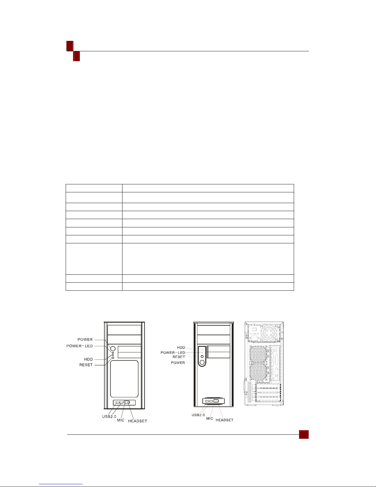
I/O Panel USB2.0 x 2; MIC x 1; SPK x 1
Power Supply Standard ATX PS2, 380W support LGA775(option)
The installation process of Chassis B540 and B541 are the same. B540 and B541 have the
same casing, but the front panel designs are different.
B540 B541 Rear
Page 2
Centurion B540/B541
English
2
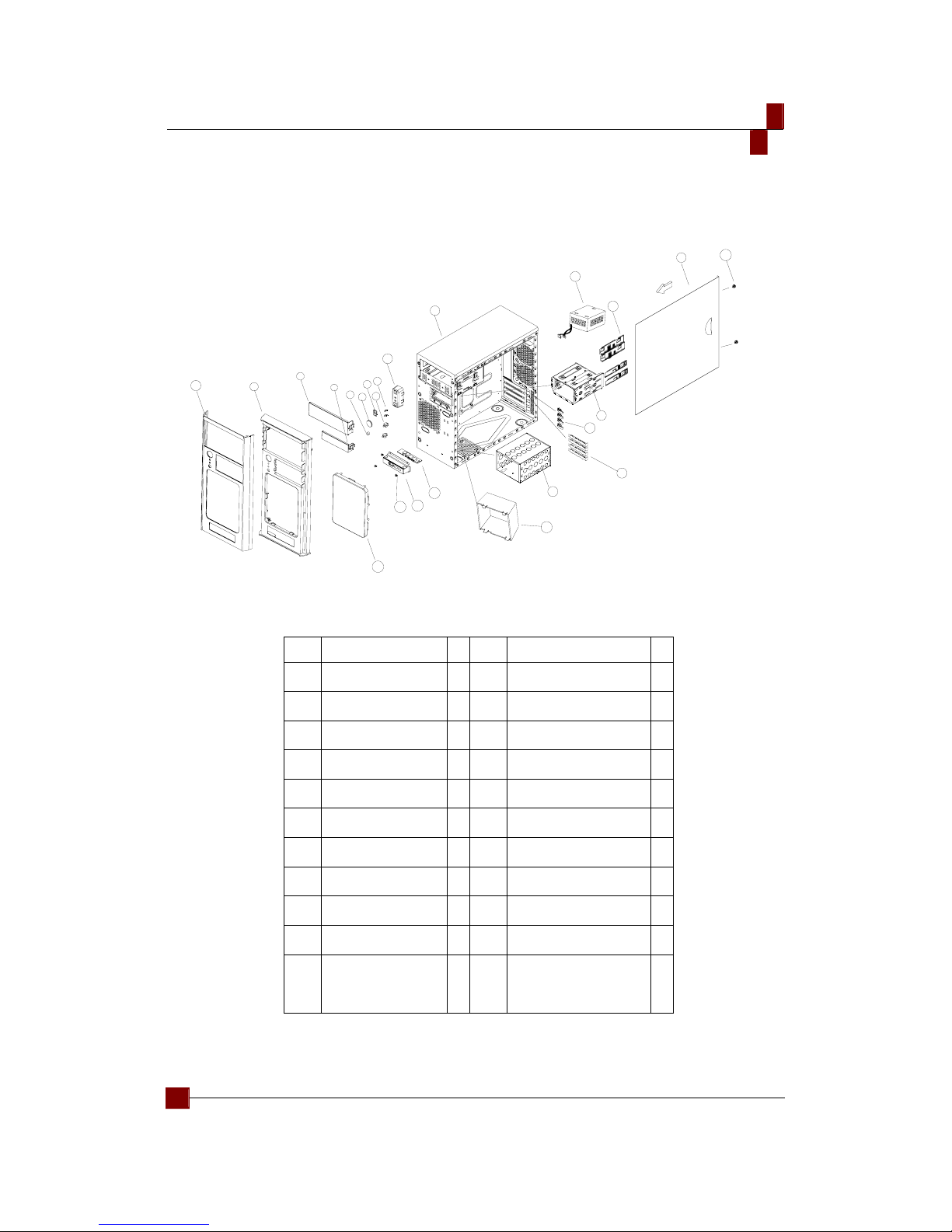
Explosion chart and Parts List
21
16
19
20
22
18
17
14
15
13
12
11
10
8
9
7
5
6
4
3
2
1
23
24
Item Parts Q ItemParts
Q
1 Aluminum Panel 1 13 Screwless device 4
2 Plastic Panel 1 14 Side Panel 1
3 5.25” shield 2 15 Screw (side panel) 2
4 3.ⁿ” shield 2 16 FDD Rack 1
5 Reset Button 1 17 Latch 4
6 Power Button 1 18 Interface Card 4
7 Light Pipe 1 19 HDD Rack 1
8 Switch Board 2 20 Fan Duct 1
9 LED Indicator 2 21 USB Board 1
10 Light Rack 1 22 USB Rack 1
11 Casing 1 23 Screw 9
12 Power (option) 1 24 Fan Filter 1
Page 3

Centurion B540/B541
English
3
Items Quantity
Parts Box(7"*3 7/8"*2 1/4) 1
Tweezers Bag (195*260*0.04mm) 1
No. 7 Tweezers 1
No. 5 Tweezers 1
No. 2 Tweezers 1
M3*5 Round Head Screws 12
6*5 Round Head Screws 7
6*8 Round Head Screws 6
540 Instruction Manual 1
5*10KT Screws 4
6*6 Hexagonal Screws 4
Cable Belt/100mm 1
Cable Belt Stand 1
6004 Locking Piece 1
6*5 Small Screw (black) 1
Φ6.5*Ø4.0*9LMM Latch(2.6 platform)
8
HDD Sliding Rail 2 SETS
28*16*7.5MM Ring 1
Chapter 2: Installation
Removing the Side Panel
1
1. Remove 2 manual screws and
slide the side panel backward to
remove it.
Page 4

Centurion B540/B541
English
4
Installing the Motherboard
2
4
3
1
1. Remove the screws on the HDD
Rack and slide the HDD Rack
backwards to remove it.
2. Lie down the casing.
3. Align the holes on motherboard and
casing and secure them with
screws.
Installing the Add-on Card
1. Press to loosen the latch on the
inner casing.
2. Insert the add-on card
3. Lock the latch back from the
outside of the casing.
Installing the CD-ROM, FDD and HDD
1
2
1. Hands on where is indicated by an
arrow and exert some force to
remove the front panel.
2. Remove the shields on the CD-ROM
and FDD from the front panel.
2
4
3
1. Remove the HDD Rack.
2. Get the HDD rails from the package
and Install it on the HDD and have
the screw holes aligned.
3. Insert the assembled HDD into the
HDD Rack.
4. Place the 5.25" and 3.5" devices in
the appropriate spots inside the
casing.
Page 5

Centurion B540/B541
English
5
1. Install the CD-ROM. and FDD into
the 5.25” and 3.5” slot respectively.
2. Locate the HDD device in place,
and align its screw holes with the
rack’s.
3. Push forward the plastic handling
and tightening it.
4. Push the lock and the installation is
done.
Installing the Power Device
1
3
2
1. Place the power device on the rack
with the cable part facing forward.
2. Secure the power device with
screws.
3. Close the casing by locking the side
panel with two screws to complete
the installation.
Replacing/Installing Fans
2
3
1
2
3
Replacing/Installing the front fan
1. Remove the side and front
panel
2. Remove the fan screws on the
front and displace the fan.
3. Replace with the new fan and
secure it with screws. The
replacement is completed.
Replacing/ Installing rear fans
1. Remove the side panel.
2. Remove the fan screws on the
rear and displace the fan.
3. Replace with new fans and
secure them with screws. The
replacement is completed.
Page 6

Centurion B540/B541
English
6
I/O Function Panel Installation Guide
z Please refer to the illustration on the section of USB2.0and Audio connector from the
motherboard user manual. Please select the motherboard which used the same USB2.0,
AC’97,HD Audio standard as below; otherwise, it will cause damages to device(s).
z The following illustration is a connection diagram for the front panel I/O cable.
z NEVER connect a USB2.0 cable to the IEEE1394 connector. Doing so will damage the
device.
z On some motherboards, the connectors for USB2.0 and Audio are not the same as the
drawing below. Please check with your motherboard manual before installing.
MIC
MIC~BIAS
FPOUT-R
+5V
FPOUT-L
MIC
AUD GND
RET~R
NO PIN
RET-L
Yellow-MIC
Red-MIC~BIAS
Bl ack-AUD GND
Green-RET~R
Green/Green-FPOUT~R
Blue-RET~L
Blue/Bl ue-FPOUT~L
Azali a ( Int el H i gh D efinition Audio) HD C onnector
AUD GND
PRESENCE#
SENSE1_RETURN
NO PIN
SENSE2_RETURN
PORT1L
PORT1R
PORT2R
SENSE_SEND
PORT2L
Yel l ow-P ORT1L
Red-PORT1R
Brown-SENSE1_RETURN
Black-AUD GND
White-PRESENCE#
Orange-SENSE_SE ND
Gray-SE NSE2_return
Green-PORT2R
Blue-PORT2R
AC'97 AC'97 Connec tor
USB+5V
LP-
LP+
GND
Motherboard Cable
Front panel USB c onnector USB connector
No Pin
USB+5V
LPLP+
GND
NC
Pin
Appendix
Contact us:
www.coolermaster.com
Email:info@coolermaster.com.tw
Headquarters, Taiw an
Tel: +886 2 32340050
Fax: +886 2 32340221
 Loading...