

Coolerator Caw07a1a1, Caw12d2a1, Caw12d1a1, Caw10d1a1, Caw10c1a1 Owner's Manual
...
Copy your Model and
Serial Numbers here.. .
When you need service or call with a question, have
this information ready:
1
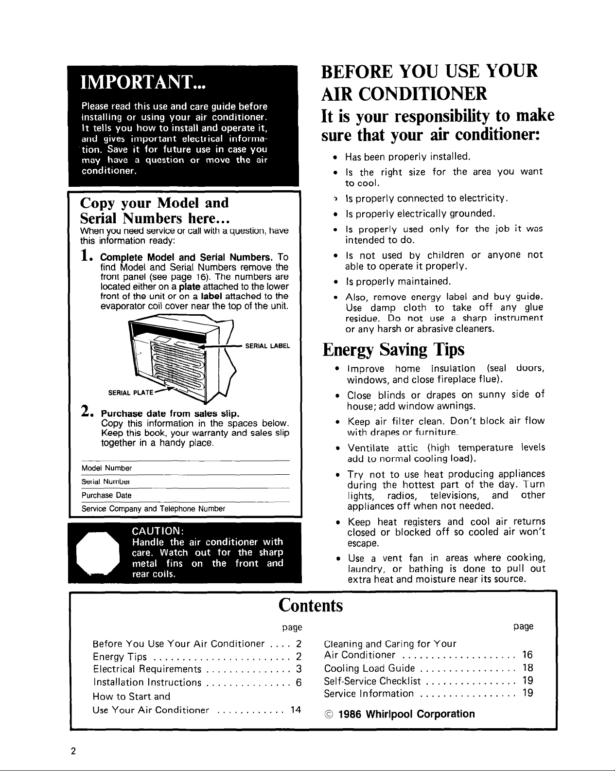
. Complete Model and Serial Numbers. To
find Model and Serial Numbers remove the
front panel (see page 16). The numbers are
located either on a plate attached to the lower
front of the unit or on a label attached to the
evaporator coil cover near the top of the unit.
SERIAL LABEL
A
L. Purchase date from sales slip.
Copy this information in the spaces below.
Keep this book, your warranty and sales slip
together in a handy place.
Model Number
Serial Number
Purchase Date
Service Company and Telephone Number
BEFORE YOU USE YOUR
AIR CONDITIONER
It is your responsibility to make
sure that your air conditioner:
l Has been properly installed.
l Is the right size for the area you want
to cool.
3 Is properly connected to electricity.
l Is properly electrically grounded.
l Is properly used only for the job it was
intended to do.
l Is not used by children or anyone not
able to operate it properly.
l Is properly maintained.
l Also, remove energy label and buy guide.
Use damp cloth to take off any glue
residue. Do not use a sharp instrument
or any harsh or abrasive cleaners.
Energy Saving Tips
l Improve home insulation (seal doors,
windows, and close fireplace flue).
l Close blinds or drapes on sunny side of
house; add window awnings.
l Keep air filter clean. Don’t block air flow
with drapes or furniture.
l Ventilate attic (high temperature levels
add to normal cooling load).
l Try not to use heat producing appliances
during the hottest part of the day. Turn
lights,
appliances off when not needed.
l Keep heat registers and cool air returns
closed or blocked off so cooled air won’t
escape.
l Use a vent fan in areas where cooking,
laundry, or bathing is done to pull out
extra heat and moisture near its source.
radios,
televisions,
and
other
Contents
we
Before You Use Your Air Conditioner . . . . 2 Cleaning and Caring for Your
Energy Tips . . . . . . . . . . . . . . . . . . . . , . . . 2
Electrical Requirements . . . . . . . . . . . . . . 3
Installation Instructions . . . . . . . . . . . . . . . 6
How to Start and
Use Your Air Conditioner . . . . , . . . . . . . 14
c
2
Air Conditioner . , . . . . . . . . . . . . . . . . . . 16
Cooling Load Guide . . . . . . . . . . . . . . . . . 18
Self-Service Checklist . . . . . . . . . . . . . . . . 19
Service Information . . . . . . . . , . . . . . . . . 19
0 1986 Whirlpool Corporation
we

ELECTRICAL
Electrical Requirememts
For Your Air Conditioner
BELOW ARE ELECTRICAL PLUG VARIA-
TIONS.
MATCHES THE AMPERE RATING OF
YOUR UNIT. THE NUMBER OF AMPERES
IS PRINTED ON THE SERIAL PLATE,
ATTACHED TO THE FRONT OF THE
UNIT,
(SEE PAGE 2).
PLUG TYPE
3.PRONG
GROUNDING PLUG
I
POWER SUPPLY
CHOOSE THE ONE WHICH
BEHIND THE FRONT PANEL
SEE ELECTRICAL
REQUIREMENTS
For 115 volt models with
serial plate amperes up
through 7.5
REQUIREMENTS
For 115 volt models with serial plate amperes up
through 7.5
OBSERVE ALL LOCAL GOVERNING CODES
AND ORDINANCES
Do not, under any circumstances, remove the
power supply cord ground prong.
RECEPTACLE WIRING
RECEPTACLE WIRING should be at least as
large as 14 gauge. Use copper wire only. It is the
personal responsibility and obligation of the
customer to provide proper and adequate
receptacle wiring installed by a qualified electrician. OBSERVE NATIONAL ELECTRICAL
CODE AND ALL LOCAL GOVERNING
CODES AND ORDINANCES.
Electrical Requirements
A 115 volt (103.5 min., 126.5 max.) 60 hertz
AC only, 15 ampere fused electrical supply is
required (time delay fuse or time delay circuit
breaker required), See Figure 1 on page 4. lt is
recommended that a separate circuit, serving
on/y this appliance, he provided.
extension cord.
Do not use an
114
BLADE
3- PRONG
GROUNDING
TYPE WALL
RECEPTACLE
RECEPTACLE
For 115 volt models with
serial plate amperes of
7.6 through 12.0
For 230 volt and 2301208
volt models with serial
plate amperes up through
12.0
Electrical Connection
Electrical Ground is Required on this Appliance
RECOMMENDED GROUNDING METHOD
For your personal safety, this appliance must be
grounded. This appliance is equipped with a
power supply cord having a 3-prong grounding
plug. To minimize possible shock hazard, the
cord must be plugged into a mating 3-prong
grounding type wall receptacle, grounded in
accordance with the National Electrical Code
and local codes and ordinances. If a mating wall
receptacle is not available, it is the personal
responsibility and obligation of the customer to
have a properly grounded 3-prong wall receptacle
installed by a qualified electrician. See Figure 1
on page 4.
Figure
1
POWER-SUPPLY CORD
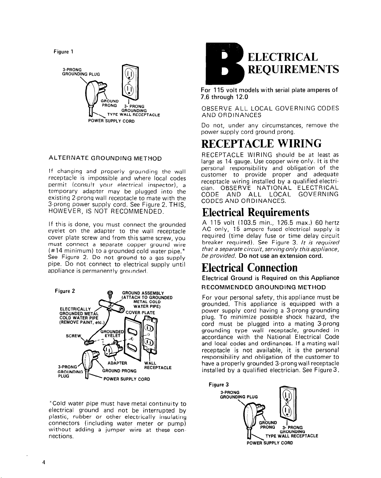
ALTERNATE GROUNDING METHOD
If changing and properly grounding the wall
receptacle is impossible and where local codes
permit (consult your electrical inspector), a
temporary adapter may be plugged into the
existing 2-prong wall receptacle to mate with the
3-prong power supply cord. See Figure 2. THIS,
HOWEVER, IS NOT RECOMMENDED.
If this is done, you must connect the grounded
eyelet on the adapter to the wall receptacle
cover plate screw and from this same screw, you
must connect a separate copper ground wire
(#14 minimum) to a grounded cold water pipe.*
See Figure 2. Do not ground to a gas supply
pipe. Do not connect to electrical supply until
appliance is permanently grounded.
Figure 2
ELECTRICALLY
GROUNDED MET
COLD WATER PI
(REMOVE PAINT, etc.
SCRE
3-PRONG ’
GROUNDING
PLUG
GROUND PRONG
POWER SUPPLY CORD
GROUND ASSEMBLY
-COVER PLATE
RECEPTACLE
INDED
*Cold water pipe must have metal continuity to
electrical ground and not be interrupted by
plastic, rubber or other electrically insulating
connectors (including water meter or pump)
without adding a jumper wire at these con-
nections.
ELECTRICAL
REQUIREMENTS
For 115 volt models with serial plate amperes of
7.6 through 12.0
OBSERVE ALL LOCAL GOVERNING CODES
AND ORDINANCES
Do not, under any circumstances, remove the
power supply cord ground prong.
RECEPTACLE WIRING
RECEPTACLE WIRING should be at least as
large as 14 gauge. Use copper wire only. It is the
personal responsibility and obligation of the
customer to provide proper and adequate
receptacle wiring installed by a qualified electrician. OBSERVE NATIONAL ELECTRICAL
CODE AND ALL LOCAL GOVERNING
CODES AND ORDINANCES.
Electrical Requirements
A 115 volt (103.5 min., 126.5 max.) 60 hertz
AC only, 15 ampere fused electrical supply is
required (time delay fuse or time delay circuit
breaker required). See Figure 3.
that a separate circuit, serving only this appliance,
be provided.
Do not use an extension cord.
lt is required
Electrical Connection
Electrical Ground is Required on this Appliance
RECOMMENDED GROUNDING METHOD
For your personal safety, this appliance must be
grounded. This appliance is equipped with a
power supply cord having a 3-prong grounding
plug. To minimize possible shock hazard, the
cord must be plugged into a mating 3-prong
grounding type wall receptacle, grounded in
accordance with the National Electrical Code
and local codes and ordinances. If a mating wall
receptacle is not available, it is the personal
responsibility and obligation of the customer to
have a properly grounded 3-prong wall receptacle
installed by a qualified electrician. See Figure3.
Figure 3
3-PRONG
GROUNDING PLUG
POWER-SUPPLY CORD
4
ALTERNATE GROUNDING METHOD
If changing and properly grounding the wall
receptacle is impossible and where local codes
permit (consult your electrical inspector), a
temporary adapter may be plugged into the
existing 2-prong wall receptacle to mate with the
3-prong power supply cord. See Figure 4. THIS,
HOWEVER, IS NOT RECOMMENDED.
If this is done, you must connect the grounded
eyelet on the adapter to the wall receptacle
cover plate screw and from this same screw, you
must connect a separate copper ground wire
(#14 minimum) to a grounded cold water pipe.*
See Figure 4. Do not ground to a gas supply
pipe. Do not connect to electrical supply until
appliance is permanently grounded.
GROUND ASSEMBLY
ELECTRICALLY
GROUNDED MET
COLD WATER PIP
(REMOVE PAINT,
A separate electrical supply is required on a
separately fused circuit. Do not fuse groundneutral.
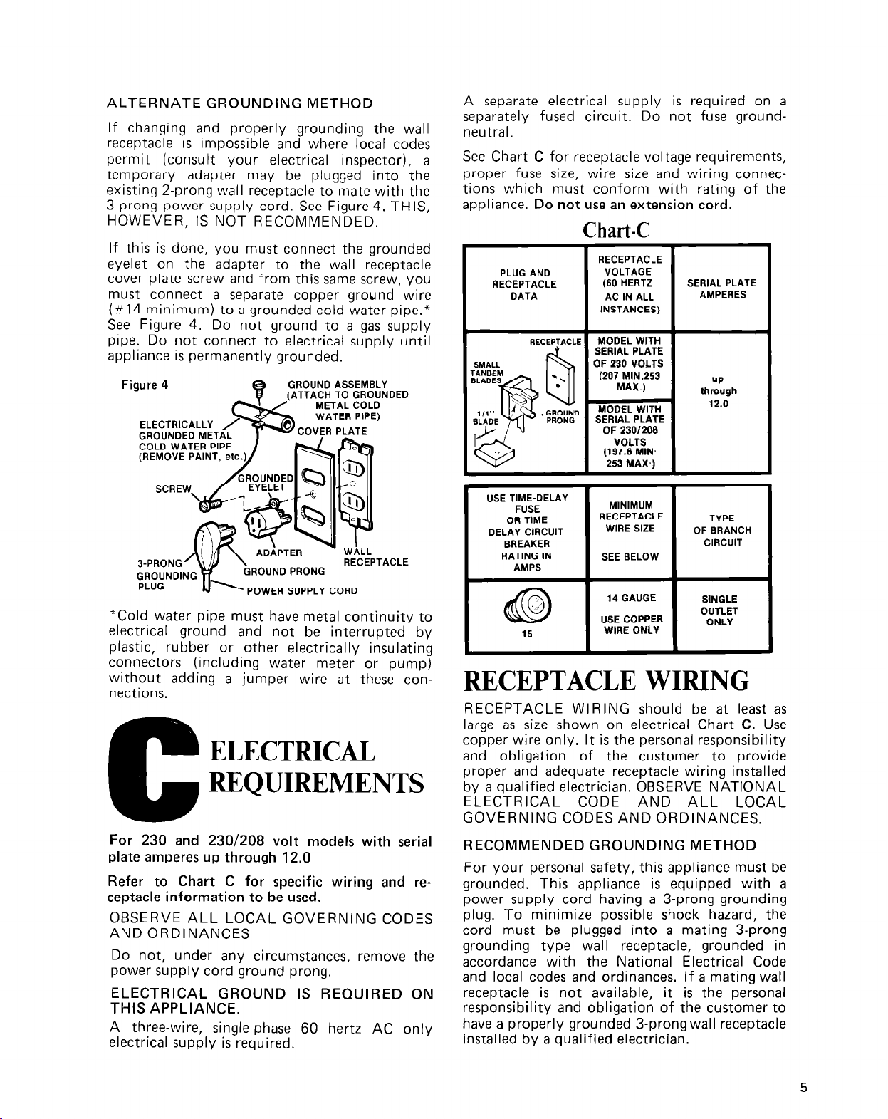
See Chart C for receptacle voltage requirements,
proper fuse size, wire size and wiring connections which must conform with rating of the
appliance. Do not use an extension cord.
Chart-C
RECEPTACLE
PLUG AND
RECEPTACLE
DATA
RECEPTACLE
VOLTAGE
(60 HERTZ
AC IN ALL
INSTANCES)
MODEL WITH
SERIAL PLATE
OF 230 VOLTS
(207 MIN,253
MAX.)
MODEL WITH
SERIAL PLATE
OF 230/209
VOLTS
(197.6 MIN.
253 MAX.)
SERIAL PLATE
AMPERES
UP
through
12.0
POWER SUPPLY CORD
*Cold water pipe must have metal continuity to
electrical ground and not be interrupted by
plastic, rubber or other electrically insulating
connectors (including water meter or pump)
without adding a jumper wire at these connections.
For 230 and 230/208 volt models with serial
plate amperes up through 12.0
Refer to Chart C for specific wiring and re-
ceptacle information to be used.
OBSERVE ALL LOCAL GOVERNING CODES
AND ORDINANCES
Do not, under any circumstances, remove the
power supply cord ground prong.
ELECTRICAL GROUND IS REQUIRED ON
THIS APPLIANCE.
A three-wire, single-phase 60 hertz AC only
electrical supply is required.
USE TIME-DELAY
FUSE
OR TIME
DELAY CIRCUIT
BREAKER
RATING IN
AMPS
MINIMUM
RECEPTACLE
WIRE SIZE
SEE BELOW
14 GAUGE
USE COPPER
WIRE ONLY
TYPE
OF BRANCH
CIRCUIT
SWGLE
OUTLET
ONLY
RECEPTACLE WIRING
RECEPTACLE WIRING should be at least as
large as size shown on electrical Chart C. Use
copper wire only. It is the personal responsibility
and obligation of the customer to provide
proper and adequate receptacle wiring installed
by a qualified electrician. OBSERVE NATIONAL
ELECTRICAL CODE AND ALL LOCAL
GOVERNING CODES AND ORDINANCES.
RECOMMENDED GROUNDING METHOD
For your personal safety, this appliance must be
grounded. This appliance is equipped with a
power supply cord having a 3-prong grounding
plug. To minimize possible shock hazard, the
cord must be plugged into a mating 3-prong
grounding type wall receptacle, grounded in
accordance with the National Electrical Code
and local codes and ordinances. If a mating wall
receptacle is not available, it is the personal
responsibility and obligation of the customer to
have a properly grounded 3-prong wall receptacle
installed by a qualified electrician.
5
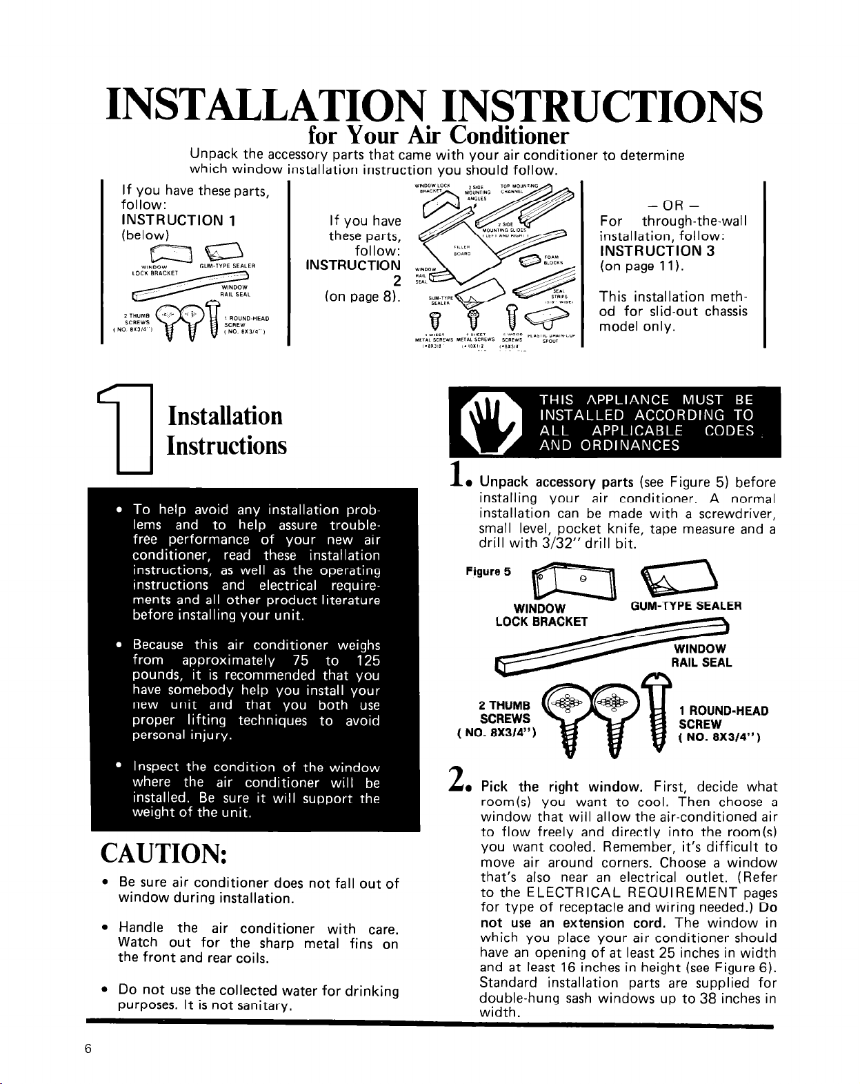
INSTALLATION INSTRUCTIONS
for Your Air Conditioner
Unpack the accessorv Darts that came with vour air conditioner to determine
which window installation instruction you should follow.
If you have these parts,
follow:
INSTRUCTION 1
(below)
mEi3
WINDOW
GUM-TYPE SEALER
Installation
If you have
these parts,
follow:
INSTRUCTION
(on page 8).
For
installation, follow:
INSTRUCTION 3
(on page 11).
2
This installation method for slid-out chassis
model only.
-OR-
through-the-wall
7-l
Instructions
CAUTION:
l
Be sure air conditioner does not fall out of
window during installation.
l
Handle the air conditioner with care.
Watch out for the sharp metal fins on
the front and rear coils.
l
Do not use the collected water for drinking
purposes. It is not sanitary.
1
l
Unpack accessory parts (see Figure 5) before
installing your air conditioner. A normal
installation can be made with a screwdriver,
small level, pocket knife, tape measure and a
drill with 3/32” drill bit.
2 THUMB
SCREWS
( NO. 8X3/4” )
2
l
Pick the right window. First, decide what
room(s) you want to cool. Then choose a
window that will allow the air-conditioned air
to flow freely and directly into the room(s)
you want cooled. Remember, it’s difficult to
move air around corners. Choose a window
that’s also near an electrical outlet. (Refer
to the ELECTRICAL REQUIREMENT pages
for type of receptacle and wiring needed.) Do
not use an extension cord. The window in
which you place your air conditioner should
have an opening of at least 25 inches in width
and at least 16 inches in height (see Figure 6).
Standard installation parts are supplied for
double-hung sash windows up to 38 inches in
width.
1 ROUND-HEAD
6
 Loading...