

Coolerado M50C, C60A Installation Manual

COOLERADO, 4430 GLENCOE STREET, DENVER, COLORADO 80216
INSTALLATION AND SERVICE PROVIDER
Coolerado Installation Manual
M50C, C60A
Version 2017-3
Date: November 30, 2017
COMPANY______________________________________
ADDRESS_______________________________________
_______________________________________________
_______________________________________________
_______________________________________________
TELEPHONE_____________________________________
WWW.COOLERADO.COM
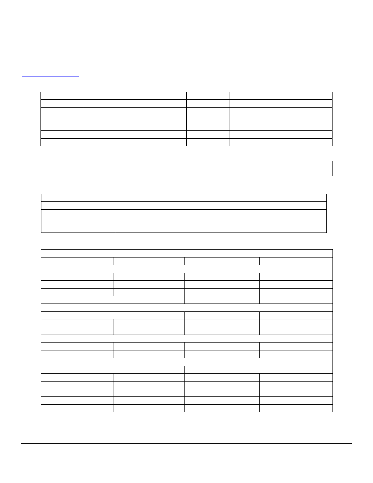
Customer Information
Installer Information
Name
Company
Address Line 1
Address Line 1
Address Line 2
Address Line 2
City City State / Prov.
State / Prov.
Postal Code
Postal Code
Phone #
Phone #
Installation Date:
Installation Information
Air Filters installed (Y/N)
Water Filter Installed (Y/N)
Water Hardness
Type of Air Filter Installed
Type of Water Filter Install
Size of Air Filter Installed
Make of Water Filter
Water Pressure @ unit
Plenum Air Pressure Measurements
Conditioned Air
Exhaust Air
Outside Air Temp
Outside Humidity Level
Conditioned Air Temp
Power
Line Voltage
Line Amperage
Phase
Control Voltage
Equipment Information
Unit Model #
Unit Serial #
Thermostat Make
Thermostat Model #
An electronic format of the Coolerado Installation Manual can be found on the Coolerado Web Site at:
www.coolerado.com
, click on Products, Unit number desired and Downloads.
MUST BE COMPLETED AFTER INITIAL INSTALLATION
Page 2 of 63

Table of Contents
Installation Notes 4
Safety Considerations 5
Installation Recommendations 5
Installation Steps
Step 1 – Check Equipment and Job Site 6
Step 2 – Inspect Filters and Heat Exchangers 7
Step 3 – Clearance Requirements 8
Step 4 – Install on Solid and Level Foundation 9
Step 5 – Drain Connections 9
Step 6 – Outdoor Intake Air 10
Step 7 – Conditioned Air Ducts 10
Step 8 – Working Air Ducts 12
Step 9 – Water Supply Connections 14
Step 10 – Electrical Power Connection 17
Step 11 – Control Wiring 18
Step 12 – Control Board Set-up and Operation 19
Step 13 – Thermostat 20
Step 14 – HMX Wet Out Logic 20
Step 15 - Operational Startup 21
Step 16 – Final Checks 22
Post Installation / Seasonal Start-up 22
Normal Operating Procedure 23
Seasonal Shutdown 23
Care and Maintenance 23
Appendix
Appendix 1 – Coolerado Water Quality Requirements 25
Appendix 2 – Control Board and Wiring Diagram 26
Appendix 3 – Water Control Board LED Indicators 28
Appendix 4 – Coolerado Thermostat Wiring Picture 29
Appendix 5 -- Multiple Unit Control Wiring 30
Appendix 6 – Thermostat Operations for (TEC2145-4) 31
Appendix 7 – Freeze Protection 37
Appendix 8 – M50B Dimensional Specifications 39
Appendix 9 – M50 Exhaust Duct Fabrication 41
Appendix 10 – M50B Air Flow Performance Table 42
Appendix 11 – M50B Curb Mount Unit 43
Appendix 12 – C60A Air Dimensional Specifications 44
Appendix 13 – C60A Flow Performance Table 47
Appendix 14 – Water Pressure Charts 48
Appendix 15 – Limited Warranty 50
Appendix 16 – Installation Check List 52
Appendix 17 – Preventative Maintenance, (PM) Checklist 57
Appendix 18 – Cleaning HMX’s 58
Appendix 18 – Troubleshooting 61
Installation Notes
Page 3 of 63

Coolerado Installation
SAFETY CONSIDERATIONS
Improper installation, adjustment, alteration, service,
maintenance, or use can cause explosion, fire, electrical
shock, or other conditions, which may cause death, personal
injury, or property damage.
Use this product only in a manner intended by
manufacturer.
Ensure the fan has completely stopped prior to
changing filters.
Before servicing or cleaning, other than changing
filters, ensure power to the unit is disconnected and
locked out.
Keep body, hands, and foreign objects away from air
intake while unit is in operation.
To avoid fire hazard, do not block any air intake.
Do not use the unit cabinet as a platform or storage.
Do not attempt to sit, stand, or climb on the unit.
Do not use the unit’s fan with any solid state speed
control device.
Consult a qualified installer, service agency, or your product
distributor for more information, or assistance. The qualified
installer or agency must use only factory-authorized kits or
accessories when modifying this product. Refer to the
individual instructions packaged with the kits or accessories
when installing.
WARNING: Follow all safety codes. Wear safety glasses,
protective clothing, and work gloves.
Read these instructions thoroughly and follow all warnings
or cautions included in literature and attached to the unit.
These instructions are intended as a general guide and do
not supersede local codes in any way. Authorities having
jurisdiction should be consulted before installation.
Recognize safety information, symbols and words:
(DANGER) will identify serious hazards, which will result in
severe personal injury or death.
(CAUTION) will identify unsafe practices, which would result
in minor personal injury or poor unit performance, product
damage and property damage.
(NOTE) will be used to highlight suggestions, which will
result in enhanced installation, reliability, or operation.
INSTALLATION RECOMMENDATIONS
NOTE: Any restrictions to air movement, either for intake
air, conditioned air, or exhaust air, will reduce the capacity
and efficiency of the unit.
NOTE: Working air (exhaust) will always be heavier than
ambient air until it fully mixes and comes to equilibrium
with outside air.
NOTE: Do not drill, cut, or compromise the powder coat
finish within the wet section of the unit. See Figure 19
The unit may be installed either indoors or outdoors.
Indoor installations require inlet air duct and
working air, (humid air exhaust), duct which may
increase costs and often add to static duct pressure
loss, create tight working spaces and require flexible
connections to allow future maintenance.
Flexible duct connectors should be installed between
any rigid ductwork and the unit to allow for leveling
requirement and to mitigate vibration. If the unit is
mounted indoors, a 2 ft. service area in front of the
Coolerado inlet fan plenum for servicing must be
designed for. The inlet air duct attached to this
plenum will need to be easily removable for
maintenance access.
Leave room for maintenance such as filter changing
on the C60 requires 25” on at least one side. If the
units are hung from the ceiling it can be difficult to
change filters.
If unit is installed indoors, install an emergency drain
pan that extends beyond the unit by at least 6” (152
mm) on all sides along with separate overflow drain
in accordance with local plumbing codes.
Be sure to provide adequate support for the unit and
associated ductwork.
Be sure that there is no exposure to flammable
vapors, excessive dust, or other contaminants in the
air.
To obtain the greatest cooling capacity, air will need
to flow into and out of the unit as freely as possible.
Humid working air must be allowed to flow freely
away from the unit and directed away from the
Page 4 of 63

Coolerado Installation
unit’s intake air supply. If ducted, ensure adequate
condensate drains are available.
The intake air opening must be kept free from
obstruction and allowed to draw in fresh dry air.
The conditioned air must be unobstructed to the
building or space to be cooled.
All ductwork must be properly sealed and insulated.
Keep all ductwork runs as short as possible between
the unit and conditioned space.
If exhaust ducts are needed they must be sealed.
If unit is installed outdoors, install rain shields as
needed.
In unheated environments, provide adequate freeze
protection for system water supply and drain.
Ensure level mounting to allow the internal water
distribution to work correctly.
If the potable water supply is considered moderately
hard, hard or very hard include a sodium-based
water softener, see Appendix 1.
properly. To reduce the shipping footprint on a C60, the
conditioned air plenum may be shipped wrapped to the inlet
of the unit rather than bolted on. If shipment is damaged or
incomplete, file a claim with the shipment company as soon
as possible. No return shipment will be accepted without
return authorization.
NOTE: The unit is shipped with air filters for initial use.
CHECK BUILDING UTILITIES AND GEOMETRY
Check for plumbing vent location
Check for exhaust vents and fumes from heaters
Check water location and hookup
Check for location of sanitary sewer drain
Check for storm sewer
Do downspouts connect to the storm sewer drain?
Check power
Check control connections
Check water hardness
LOCATION OF EQUIPMENT
Select a location for the unit as close as possible to the supply
air diffuser and away from any building exhaust or sources of
high humidity levels.
NOTE: If tying into existing HVAC equipment check for
complete functionality before starting any work.
NOTE: Make any necessary duct modifications to implement
seasonal Duct Blocks during initial installation.
It is recommended that off-season duct blocking devices be
installed as part of the end-of-season shutdown procedures.
Step 1—Check Equipment and Job Site
CAUTION: Take the necessary precautions and use
appropriate equipment to move and install.
INSPECT PACKAGING OF EQUIPMENT BEFORE ACCEPTANCE
Check the unit for any signs of shipping damage before
accepting equipment from the freight carrier. If shipment is
damaged do not accept shipment or it may become yours as
is. If damaged, file an immediate claim with the shipping
company. No return shipment will be accepted without
written return authorization.
UNPACK UNIT
Move to final location. Remove carton or packaging, taking
care not to damage unit.
INSPECT EQUIPMENT
Check the unit for any signs of shipping damage. Fan should
spin freely and all covers and parts should be secured
NOTE: Prevailing winds and building geometry must be
taken into consideration in determining air inlet and
exhaust locations. Additional ductwork for either the intake
or exhaust may be required to assure proper separation of
the air streams.
Prevailing wind consideration, Figure 1
NOTE: Inlet hoods should not be located near driveways,
parking lots, gas meters, oil fill pipes, dryer vents or other
Page 5 of 63
Coolerado Installation
Model
Filter Size
M50C
3- 2”x20”x25” (50x500x625 mm), nominal
pleated filter size, not recommended)
C60A
4- 2”x16”x25” (50x500x625 mm), nominal
pleated filter size, not recommended)
areas. Avoid areas where objectionable vapors,
contaminants, or excess particles could be drawn into the
unit. Humid working air must be directed into a free air
outdoor space and away from any condensing surface.
NOTE: Humidity sources include the Working Air exhausts
from the unit itself or from adjacent units, cooling towers,
open drains, grass, bushes, trees, swampy areas, swimming
pools, water features, plumbing vents, etc.
DANGER: Do not expose the unit intake air to flammable
liquids or vapors and away from excessive dust sources.
LIFTING EQUIPMENT
Forklift / crane
Crane
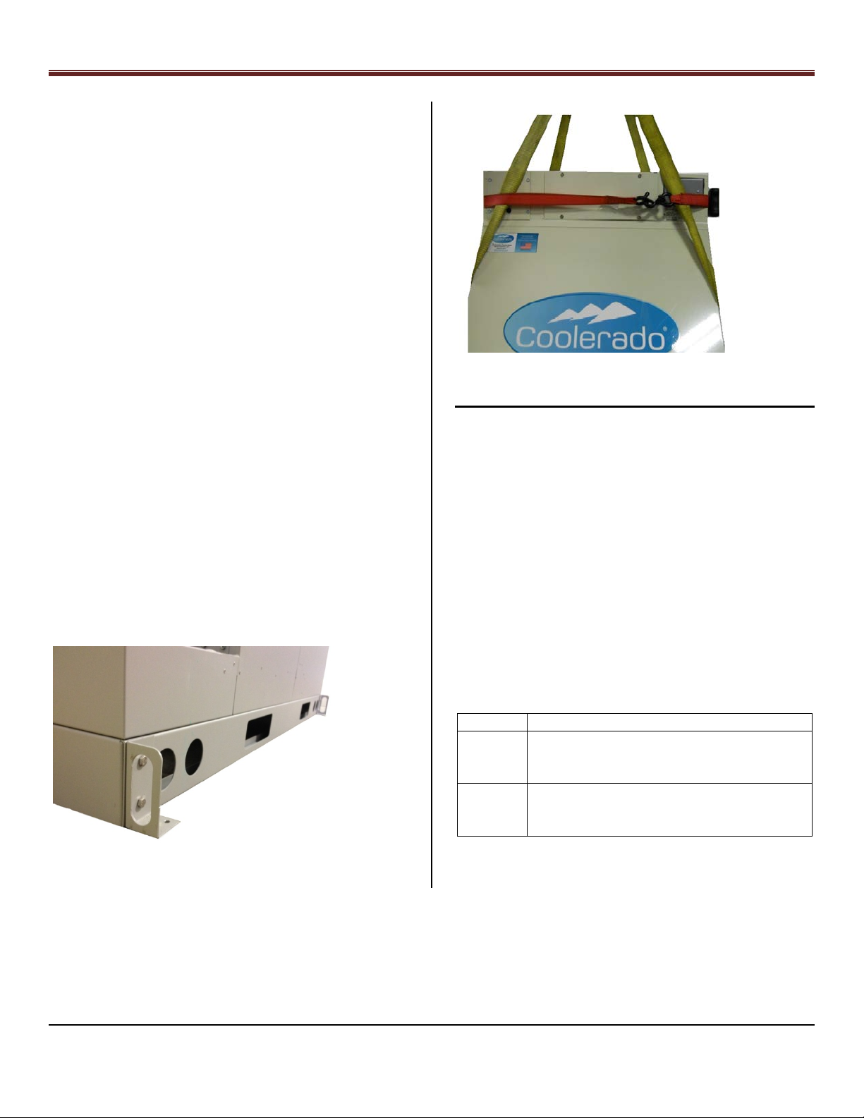
Straps and spreader bar
Upper security banding (as seen below)
The lifting point above the unit must be at least 4’ (1.2 m) or a
spreader bar is needed to prevent squeezing the box.
Care should be taken not to rack or torque the units when
moving or lifting units into position as this may cause poor
door fitting, Heat and Mass Exchanger racking and leaking, air
leaks, etc.
Lifting Straps/Banding, Figure 3
Step 2— Inspect Filters and Heat Exchangers
1.) Inspect the unit’s filters for damage or debris.
2.) Spin the fan for freedom of movement.
3.) Remove filters and inspect heat and mass
exchangers (ensure flow arrow on filter is correct).
4.) Inspect surfactant soap container for proper level.
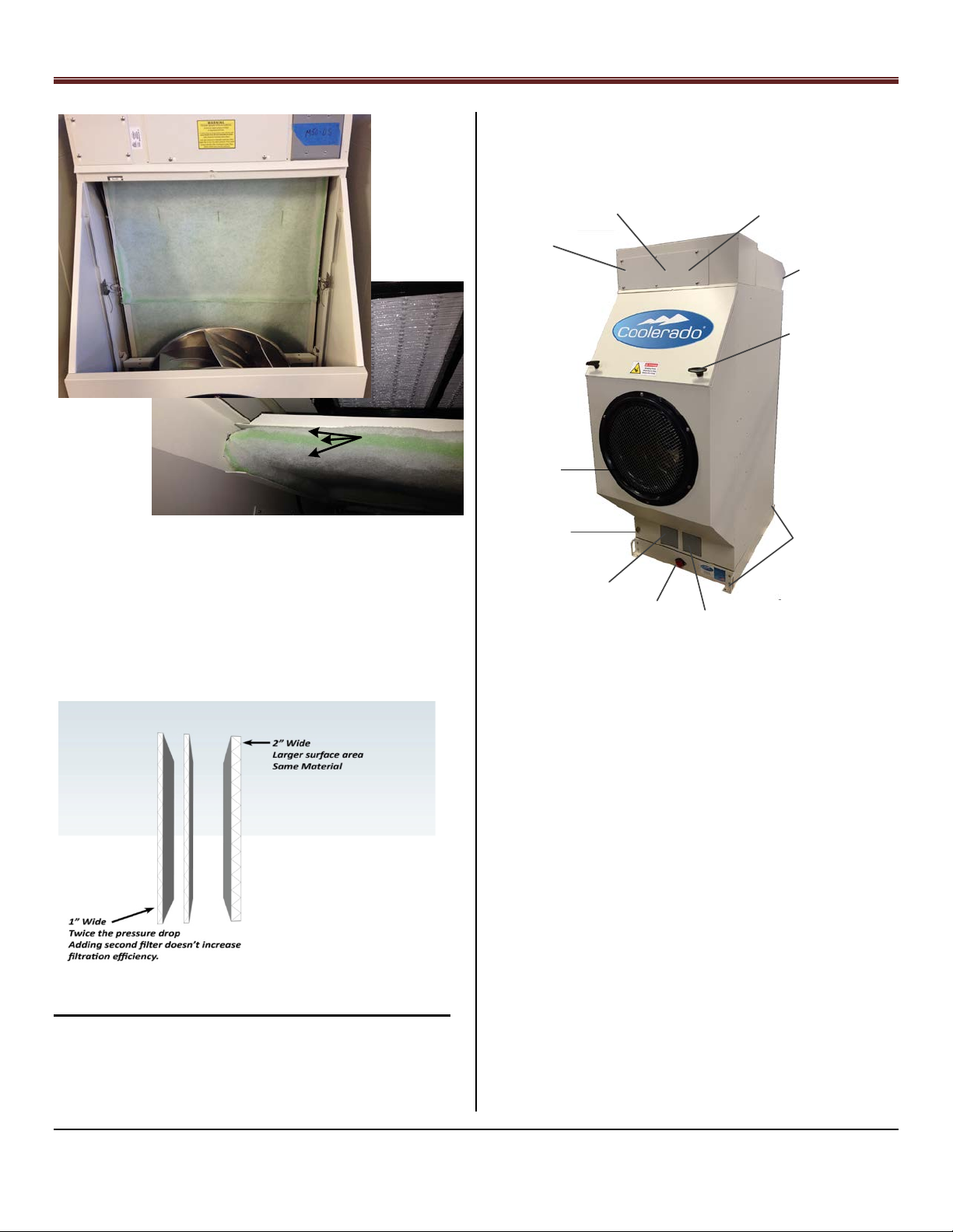
NOTE: Coolerado provides three ply panel filters with about
a MERV 8 rating. This is a depth loaded synthetic media that
will hold twice the dirt than the pleated filters with the
same pressure drop. They also do not allow dirt bypass
round the perimeter or between filters, are not affected by
water and are about the same cost. We highly recommend
replacing filters with panel filters.
1.75”x19.5”x24. 5” (44.5x495x622mm), (actual
1.75”x15.5”x24. 5” (44.5x495x622mm), (actual
M50C Lifting Lugs, Figure 2
Page 6 of 63
Coolerado Installation
Exhaust Out Back,
(Removable for Duct
Installation)
High Voltage Power
Factory Wired
Connections
Soap
Pump
Control Wiring,
Low Voltage
Do Not Block
Filter Access Door
Filter Access
Door Handles
Lifting Lugs
Drain
Water In
Low Voltage Wire
Terminals In
High Voltage Wire
Terminals In
Outdoor
Air In
Panel
Filter
3
-
Ply Panel
Filter
2.) Familiarize yourself with the unit’s connection and
service points. See Figure 6.
3-Ply Panel Filter, Figure 4
DANGER: Do not expose the intake air to flammable liquids
or vapors.
CAUTION: Do not substitute 2” (50 mm) filter with two 1”
(25 mm) filters, this will significantly reduce the airflow
through the unit. See Figure 5
Step 3—Clearance Requirements
1.) Inspect clearances and position the unit for
installation – see Appendices 8, 10 or 12 for unit
dimensions and clearance details per model.
Filter image, Figure 5
Identifying System Components, M50C, Figure 6
NOTE: Ensure unit is positioned so that filters, soap pump
and electrical service areas are easily accessible for
maintenance and seasonal changes.
NOTE: Figure 7 shows the working exhaust air from the top.
For units using side working air exhaust.
CAUTION: Ensure a minimum of 24” (610 mm) clearance for
side mounted working air exhaust.
NOTE: Take precautions not to block service areas of unit
and that the ductwork connection has enough flexibility for
leveling or seasonal re-leveling purposes.
Page 7 of 63
Coolerado Installation
Outdoor Air
Inlet
Supply Air
Exhaust Air
Note, Opening cut into Supply
Plenum by Contractor
Outdoor Air
Inlet
Contractor
Fabricated
Exhaust Duct
Supply Air
Exhaust Air
Clearances:
-- Sides: 0
-- Top: as needed for installation
-- Outside Air Intake to Fan: 24" (600 mm)
-- Supply Air Plenum: as needed for
installation
structural engineer and comply with local code
requirements.
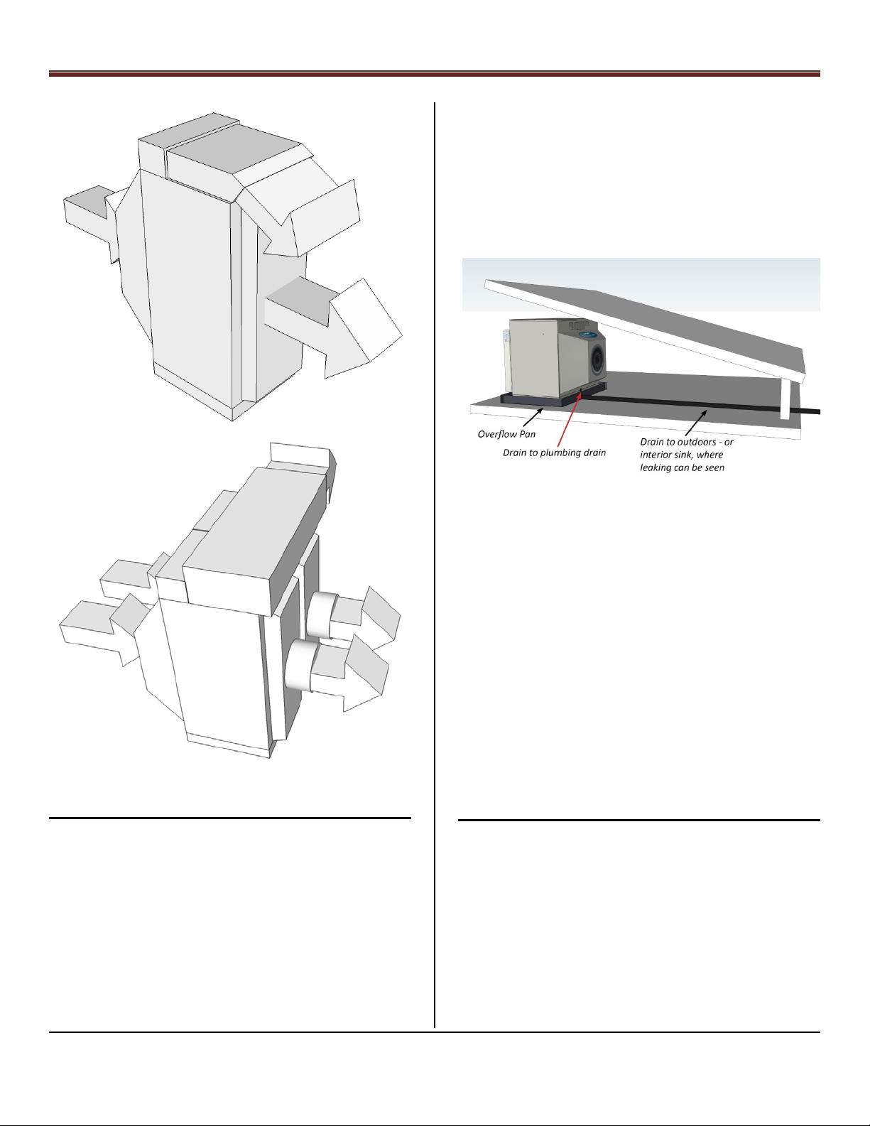
If unit is installed indoors, install an emergency drain pan that
extends beyond the unit by at least 6” (150 mm) on all sides
along with separate overflow drain directed to a sink or
outside location where the leak can be seen and in
accordance with local plumbing codes, see Figure 9.
Step 4— Install on a Solid and Level Foundation
Mount the unit on a solid and level foundation with
proper sub-base and drainage to ensure the unit will
not shift during its lifetime.
Take the proper precautions when mounting the
unit to reduce noise and vibration.
If mounted on rafters, use appropriately sized
vibration damping springs and duct isolation
attachments.
If installed on a roof, an attic, or any place where
structural support may be an issue, consult with a
Clearance Requirements, Figure 7
Overflow/Drain Example, Figure 9
LEVEL UNIT
The weight of the wet unit will require a stable base. During
installation, the unit must be properly supported and leveled
to stay stable over time. The water delivery to all areas inside
the unit depends on the unit being level within 1/16” per foot
(5.2 mm/meter) in both directions. CAUTION: Failure to do
so will void system warranty.
CAUTION: Foundation racks or solid drainage
footing/concrete pads must be used on ground installations
to ensure the unit remains level and secure. Proper
preparation of ground is necessary to maintain level footing
over time.
CAUTION: Do not place unit directly underneath roof, eaves
or drip lines without adequate gutters.
Step 5 – Drain Connections
NOTE: The units drain connection is located underneath the
unit’s intake air plenum.
Install system drain piping that can be 1 ½” (38.1 mm) pipe
over outside; 1 ¼” (31.75 mm) inside or 40mm deeper inside
If local or state codes allow drain water to be used for
Irrigation, it must be drained away from the pad to eliminate
any settling that will prevent the unit from remaining level. If
this occurs, the drain line must slope a minimum of 1/8” per
foot (10.4 mm/meter).
Page 8 of 63
Coolerado Installation
Model
Intake Duct Size
Intake Duct Size
M50
20 inches
500 mm
C60
22 inches, (20” at fan
inlet)
560 mm, (508 mm
at fan inlet)
Pooling of water near the unit will also allow excess humidity
to be drawn into the unit, which will reduce the cooling
performance of the unit.
CAUTION: Do not discharge to roof top drains that drain to
parking lots or alleys. (The continual flow of water will cause
a slick green alga growth).
Drain Connection, Figure 10
If the unit drain line is connected to an internal building
sanitary sewer drain line, it must feed into a 1-1/4” (40mm),
(or larger) plumbing drain line that meets all plumbing code
requirements. The drain line must be vented as it enters the
building sanitary sewer drain line.
NOTE: If rigid duct is used to connect to the unit’s intake air,
it must be designed to be easily removed to allow service
access.
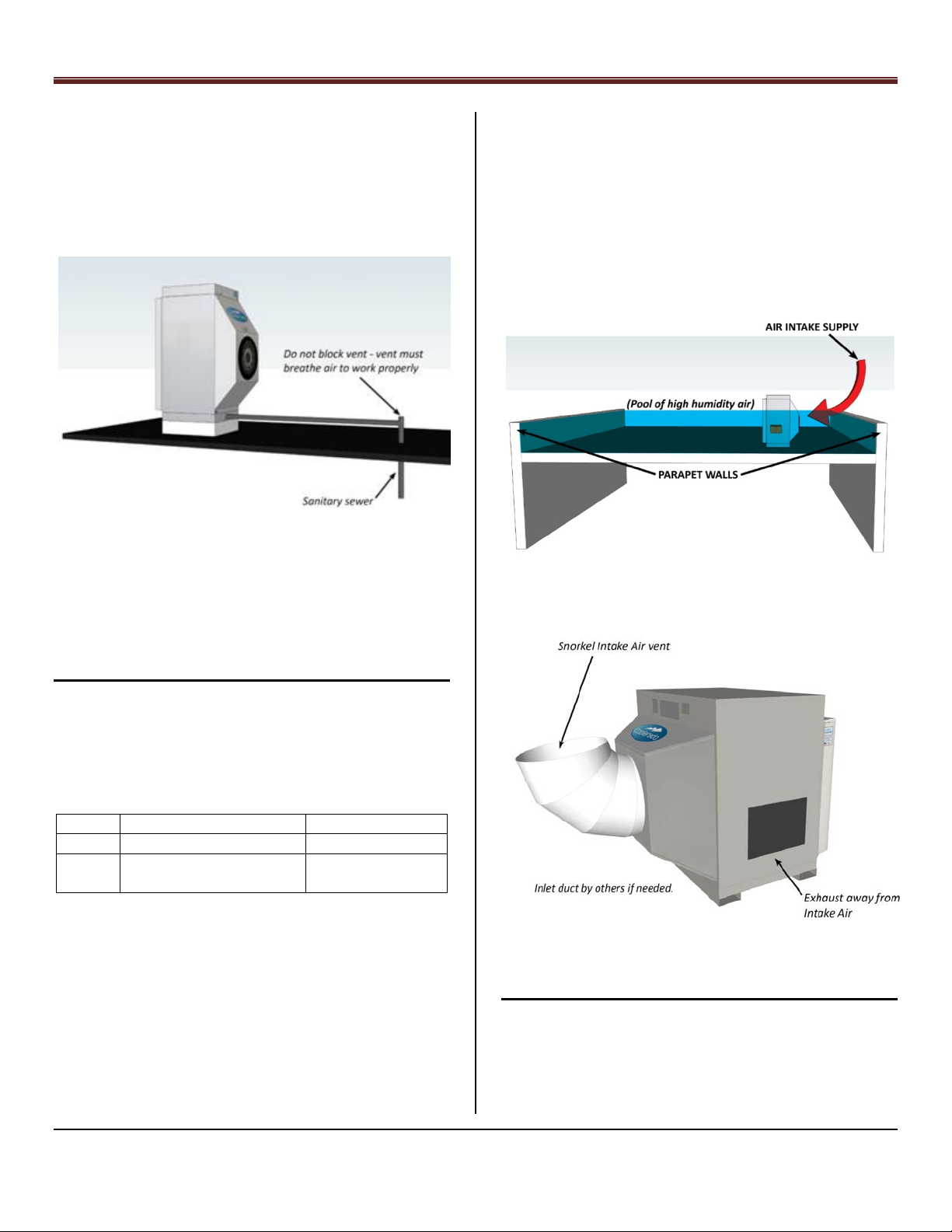
NOTE: In some roof top installations, parapet walls can trap
the heavy cool humid working air below the walls causing
the intake air to have a high humidity resulting in higher
conditioned air temperatures. In these situations, the intake
air may need to be brought from a higher location, see
Figure 11.
High Parapet Walls, Figure 11
Step 6—Outdoor Intake Air
NOTE: The intake air duct must not be located near the units
working air duct.
Install and inspect ductwork if needed.
The intake air can enter the unit directly or through a
properly sized duct. Use intake sizes from Table 1:
Intake Duct Sizes, Table 1
NOTE: If the unit is installed in a building (attic or other) a
duct may be needed to draw fresh intake air into the unit
from outside the building.
NOTE: The free open area of the intake grill must equal the
duct area. Failure to do so may cause excessive pressure
drop across the grill, see duct sizes in Table 1.
Intake Snorkel, Figure 12
Step 7 –Conditioned Air Duct
1.) Install properly sized, sealed and insulated
conditioned, R6 minimum, air duct to unit.
2.) For all units the conditioned air plenum is shipped
without pre-cut duct openings. This allows the
installer to add the ducts where desired on location.
Page 9 of 63
Coolerado Installation
Duct openings should only be cut into the front of
the supply plenum. DO NOT CUT OPENING IN THE
BOTTOM OF SUPPLY PLENUM or within 2” (20mm)
of the bottom. Coat and seal any exposed metal, see
Appendices 8, 10 and 12.
NOTE: Seasonal shut off dampers or easily accessible duct
blocks should be installed for easy winterization
changeover.
NOTE: A flexible duct connector should be installed between
the unit and any rigid ductwork to allow for seasonal
leveling and to mitigate vibration.
Recommendations for reducing temperature loss and
creating displacement ventilation conditions:
The air pressure at the units conditioned air plenum
should be 0.01 to 0.15 inches of water column (2.5
Pa to 37 Pa) greater than the working air exhaust
plenum under full air-flow. This will prevent water
migration from the exhaust side to the conditioned
air-side and provide adequate working air.
Ductwork Example, Figure 13
Seal duct work.
If the conditioned air ducts are located external to
the building or in an attic space, a minimum of R6
insulation is required. Follow local building and
insulation code requirements.
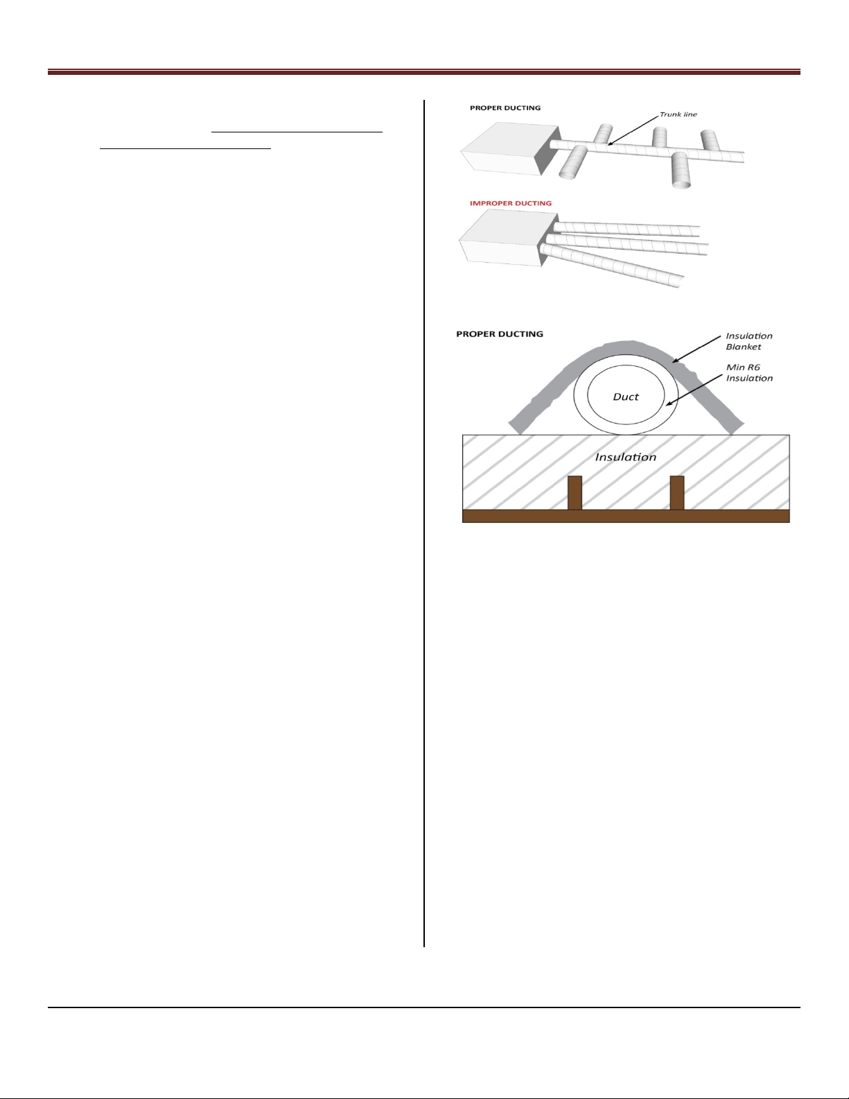
Size ducts to about 0.08 inches of water column per
100 feet (66 Pa per 100 m) of duct. Typically, a
round duct connection to the C60 or M50 supply or
conditioned air plenum would be a 16 inches
(400mm) in diameter.
Maximize the trunk duct and minimize the length of
duct branches, see Figure 13.
Too many air-drops can cause excessive temperature
losses.
Large, non-mixing type diffusers (positioned low) are
recommended.
High ceiling installations should direct the air down
at low velocities, less than 200 ft/min (60 m/min),
preferably 50 ft/min (15 m/min). Do not mix air, see
Figure 18.
Duct Insulation, Figure 14
NOTE: Additional duct insulation may be required in high
heat gain areas such as attics, see Figure 14.
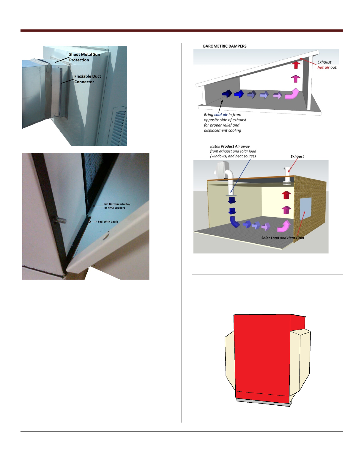
CAUTION: To get proper air movement it is sometimes
necessary to install several barometric dampers and/or
building exhaust fans.
NOTE: Adjust barometric dampers to optimize air
distribution.
Diffuser location examples:
Installation of a room diffuser might have the
conditioned air delivered at the opposite side of the
room from the door and sweep toward the door to a
barometric duct in the ceiling, see Figure 17.
A room with a window may have the diffuser
installed on the opposite side from the window, with
cooled air sweeping the room toward the window
and removing the hot air above the window, see
Figure 18.
NOTE: Avoid sharp bends and sudden reductions in ducting
causing pressure drops which impede air-flow.
Page 10 of 63
Coolerado Installation
Conditioned Air Plenum Duct Connection Figure, 15
C60 Conditioned Air Plenum inside Box, Figure 16
NOTE: Set the conditioned air plenum inside the box or the
HMX frame so that water will be directed into the box
rather than to the outside. Seal outside edge at bottom of
plenum, see Figure 16.
Barometric Damper Example, Figure 17
Installation Example, Figure 18
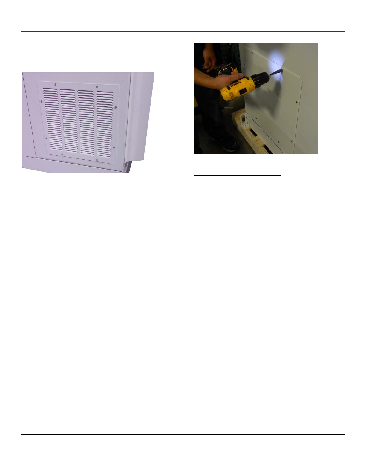
Step 8 – Working Air Ducts, (unit exhaust)
NOTE: Do not drill, cut, or compromise the powder coat
finish in the wet section or behind the HMX’s or drive
screws into filter areas or where internal wiring, soap
bottles, etc has been installed. See Figure 19
NOTE: The conditioned air plenum is not insulated in the
factory. Insulate plenum after duct holes have been cut out.
In outside installations, the plenum should be fully insulated
and sealed to reduce air temperature increases within the
plenum. Any increase in the conditioned supply air
temperature will result in an increased building temperature
and run time.
NOTE: Barometric Dampers and /or building exhaust fans
are installed to relieve conditioned space pressure at the
highest temperature locations.
Wet Area, Figure 19
Page 11 of 63
Coolerado Installation
Air Block
Plate
If units are located inside or multiple units are
mounted side by side requiring a common working
air duct:
o Seal ducts to prevent condensation from
leaking from the ducts
o Provision must be made for the duct to
drain condensation back to the unit.
Connect to an appropriate drain if ducting is
lower than unit. Duct joints should be
constructed to drain water such that it will
not catch in seams.
Top Mounted Exhaust, C60A, Example, Figure 20
screw holes in M50C to mount ducting such as in a building to
exhaust air outdoors. See Appendix 11 for duct details.
Note: When using a 3-phase, 480 VAC factory installed
motor, considerably more air flow and pressure drop can be
obtained. A 5.5” high by 9” wide plate has been included to
block the exhaust flow when the Supply air static pressure
exceeds 0.6”. The plat clips into the expanded metal bird
guard screen.
NOTE: C60A, if side louvers cannot be used, it is suggested
to extend the exhaust duct so that it is approximately 12 in
(30.5 cm) above the rooftop. This will help to prevent
working air from entering the system and decreasing
performance.
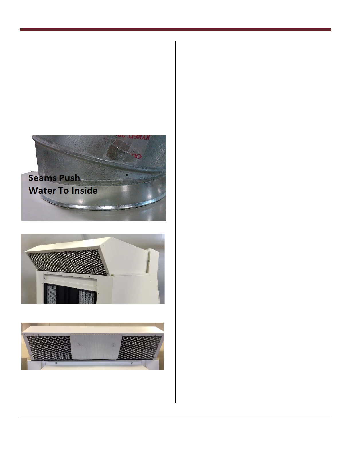
CAUTION: All duct connections to the unit must be able to
drain back into the unit. Ensure duct flanges mount to the
inside of the cabinet to prevent leakage of condensate. See
Figure 20 for an example.
CAUTION: Failure to prevent sunlight from reaching the heat
exchanger will allow degradation of the heat exchanger
material and possibly allow green algae growth if there is
enough dissolved nutrients in the water supply and or air.
The Clean HMX material will not support mold or algae
growth.
Top Factory Mounted Exhaust, M50C, Figure 20
Air Block Plate for use with M50 3 Phase Fan, Figure 21
The top mounted exhaust hood on the M50C is removable
and can be replaced with rectangular ducting. Use existing
CAUTION: A bird screen must be installed over the outlet
exhaust to keep birds and squirrels out.
CONSIDERATIONS: The working air is always cooler than the
outside air. This air can be used to cool the back of solar
panels or directed to condenser coils (Most applications that
will not be affected by moisture).
CAUTION: Working air being drawn into the intake air will
seriously impact the temperature performance of the unit
and add significant humidity to the inside of the building.
When installing the unit on the roof or ground, use working
air louvers with protective screening (these louvers are sold
separately). Using louvers other than those supplied by
Coolerado may void the warranty.
NOTE: At least 24 inches (600 mm) should be left between
side louvers and any object to allow free air-flow.
Additionally, this will allow access for the louver panel
(which houses a filter pad that prevents water from spitting
from louver).
NOTE: Side louvers may have some condensation and excess
water carry over from the working air (which may contain
Page 12 of 63
Coolerado Installation
minerals) and should be located where mineral buildup
outside the unit will not be a problem.
Exhaust Louvers, Figure 22
C60A units are shipped with precut holes for louvers.
NOTE: two (2) side louvers are required for C60A’s to
prevent spiting from the side of the unit.
CAUTION: The working air expels excess water, minerals and
salts at all times it is in operation. Any holes cut into this
section or screws attached must be coated on the inside
with a high quality duct sealer to prevent corrosion. In most
cases the HMX’s will need to be removed to adequately seal
any punctures to the inside of the working air section and
prevent rusting of the box. This may void warranty if not
properly sealed.
Side Cover and Louver Attachment:
To seal the side covers or louver very little torque is needed
to tighten the screws. Over tightening will cause warping of
the cover or louver. Eight (8) 10 – 32 stainless steel screws
are used to hold the louvers or covers on. The unit comes
with matching blind rivets mounted in the box.
Inside Cover, Figure 23
Step 9 – Water Supply Connections
Note: Do not turn water on unit till Step 15.
See Appendix 14 for line size and pressure charts.
CAUTION: Clean potable water should be connected to the
Coolerado air conditioner, see Appendix 1 Coolerado Water
Quality Requirements for more details.
CAUTION; Do Not use galvanized or black iron piping
anywhere in the water supply system.
Water lines should be insulated from heat sources such as the
sun to prevent overheating and scaling of the water. If the
water line insulation will see sun light at any point it should
be UV protected material. When hard water is heated, it
increases its scaling potential such as in a water heater.
NOTE: When choosing to insulate exposed water lines, UV
protection must be accounted for. If using non-UV rated
insulation, it is suggested to coat the insulation with a
weatherproofing finishing paint or jacket.
The instantaneous water flow rate to the HMX’s is the water
required when turned on by the water control board. The
water is turned off most of the time. A clean and consistent
water supply capable of instantaneous 85 GPH (gallons per
hour) (322 LPH(liters per hour)) for a M50, and 102 GPH
(386 LPH) for a C60, for proper operation of the units.
NOTE: Install a hose bib at the main water line near the unit.
This will allow for quicker and easier servicing as well its
double use for cleaning the units.
Page 13 of 63
Coolerado Installation
HMX Water Usage (gal/HMX
Water Usage (Liters/HMX
Model
Number of HMX’s
M50
5
C60
6
NOTE:
water usage and drains on a continuous basis
It is also suggested to install ½ in. ball valves to the
main water line of the unit if installing multiple.
This will allow individual units to be shut off during
maintenance rather than shutting all units off.
The water connection is a ½” (12.7 mm) FNPT at the unit
base. The water pressure at this connection must be between
40 psi (225 kPa) and 80 psi (550 kPa). For your convenience,
Appendix 14 provides water pressure drop information. Note
that the water pressure will decrease 1 psi for every 27.7”
(9.8 kPa for every 1 m) of height do to gravity. So for a 30’
(9.14 m) rise, the water pressure will decrease by 13 psi (90
kPa), this does not include pressure drop due to friction in the
piping and pipe fittings.
Note: A Water Pressure Switch has been installed on the
water line inside the unit that will disconnect the fan control
wire turning the fan off until the water pressure rises again,
see Figure 25. This means a dirty water filter or low water
main pressure will turn the fan off. If the main water
pressure is low a, booster pump may be required.
16.0
-hr)
14.0
12.0
10.0
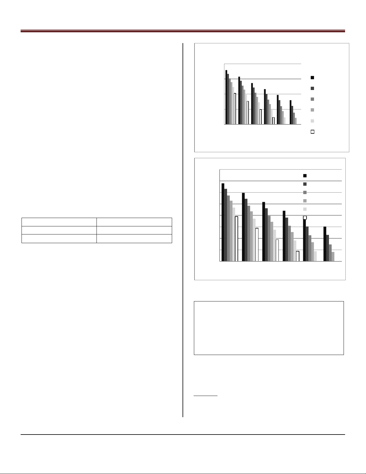
Coolerado Water Usage per HMX
4.0
-hr)
3.0
2.0
1.0
0.0
110 100 90 80 70 60
Ambient Temperature (F)
Coolerado Water Usage per HMX
8.0
6.0
0 F Dew Pt
20F Dew Pt
40F Dew Pt
50F Dew Pt
60F Dew Pt
70F Dew Pt
- 18C Dew Pt
- 7 C Dew Pt
4 C Dew Pt
10 C Dew Pt
16 C Dew Pt
21 D Dew Pt
CAUTION: Dynamic water supply pressure of between 25 PSI
(172 kPa) and 80 PSI (550 kPa) is required at the unit.
Water Consumption:
Water consumption or water usage is based on the outdoor
temperature, humidity and air flow rate. The water is turned
off for two minutes than back on for the length of time
needed to keep the HMX’s with adequate water. The water
usage is shown in the attached tables.
4.0
2.0
HMX
0.0
43 38 32 27 21 16
Ambient Temperature (C)
Water Consumption Table (per HMX), Figure 24.
1. Assume full product flow rate at 1400 cfm or 40
3
/min (M50)
m
2. Water usage rates are +/- 15%
3. Drain water equals approximately 25% of total
WATER FILTER
WARNING: INSTALL the IN-LINE 30 micron WATER FILTER
supplied with unit. The water filter should be installed
upstream (before) any solenoid valves or water pressure
regulator on the Coolerado unit so that these devices will be
protected by the water filter.
Page 14 of 63
Coolerado Installation
Check Val ve , CV
Booster
Pu mp
Pressu re
Tan k
Pressu re
Gaug e
Union
Relief Valve
Pressu re
Sensor
Circuit Breaker
Disconnect (110VAC, 20 amp)
Cont rol for Boost er Pu mp
Need 25 psi (172 kP a)
Minimum at Coolerado Unit
By Co ntr a ct or :
CV
Main Water Line
Hose Bib
Ball Valve
CAUTION: Failure to install an in-line water filter will void
system warranty.
NOTE: In addition to water pressure, water quality has a
major impact on performance. Reducing undissolved
particulates increases performance and longevity of the
system’s heat exchangers.
The filter will need to be changed when the pressure drop
across the filter reduces the main line water pressure below
25 psi at the units when they are calling for water, the toilets
are being flushed and the irrigation system is running.
Realistically the water pressure needs to be at least 40 psi.
How fast a water filter needs to be replaced depends on the
amount of un-dissolved minerals or debris that is in the
water.
NOTE: If incoming water pressure is more than 80 psig (550
kPa), a pressure-reducing valve should be installed to the
incoming water supply line.
WATER PRESSURE REQUIREMENTS
NOTE: If incoming water pressure is ever less than 25 psig
(172 kPa) when the unit is running, a water pressure booster
pump may be required. District water line pressures are
often decreased due to irrigation activities, especially at
night. A minimum building pressure is generally 40 psi to
maintain the pressure at the unit of 25 psi when considering
water filter pressure drop, perhaps a water softener, toilets
being flushed, the units may be mounted on the roof
causing pressure loss due to gravity and height, and the
irrigation system running.
Water Booster, Hose Bib, and Ball Valve, Figure 25.
NOTE: Use a minimum of 1/2” (12.7 mm) diameter supply
water line, which should be free draining for winter shut
down.
BACK FLOW PREVENTION
NOTE: The unit is equipped with a self-draining water
regulating valve designed with a vacuum break in the HMX.
Low Water Pressure:
In certain locations, a reduction or potential loss of water
pressure can occur due to high demand conditions on the
municipal or district water supply. Install a booster pump to
ensure water pressure is maintained. If required, mount
booster equipment near ground level, see Figure 25.
Water Distribution System – M50C, Figure 26
Freeze protection can be done manually:
1.) Install supply water shut off valve between the
water supply line and the unit.
2.) Install a drainage valve downstream of the manual
water valve. The drain valve should be located within
a conditioned space.
Page 15 of 63
Coolerado Installation
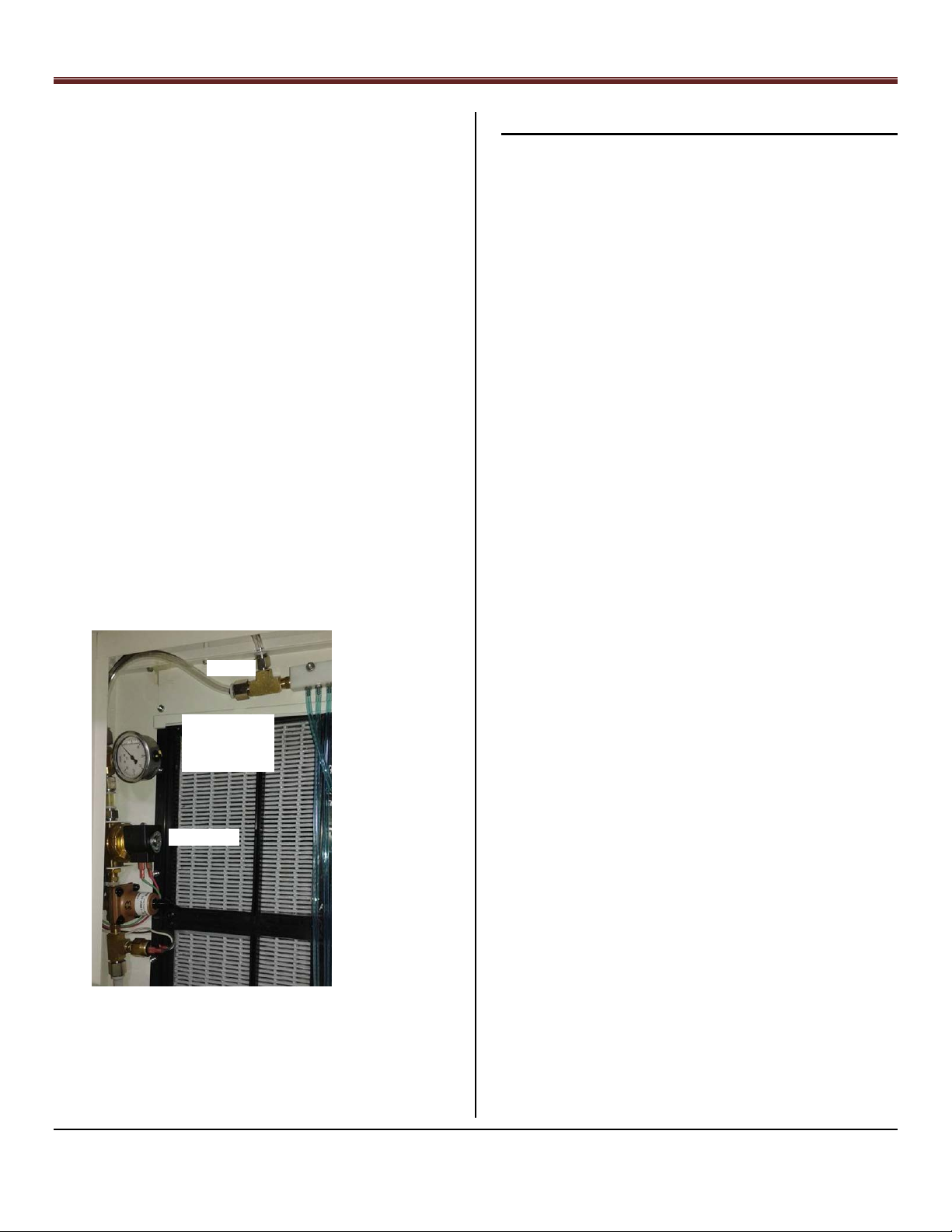
Measure Header
Pressure Between
Solenoid Valve and
Soap Tee Using ½”
OD Tube Connectors
Solenoid Valve
Soap Tee
3.) Slope the line from the unit to the drain valve for
proper draining and freeze protection.
4.) To drain the line and water distribution system it
must be turned on for a few minutes to allow the
water to drain and air to pulled into the system. This
is done by turning the thermostat to require a cool
call.
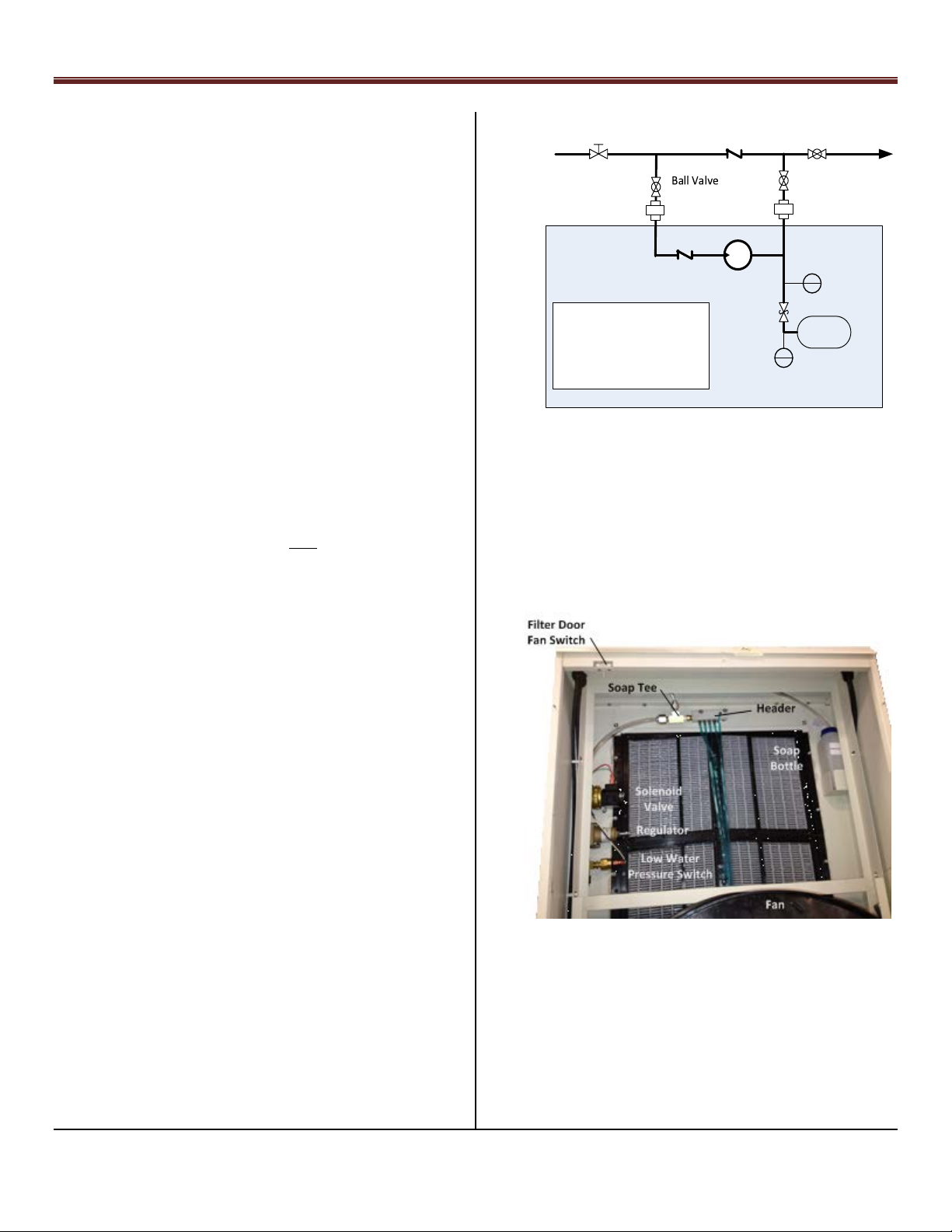
WATER DISTRIBUTION SYSTEM
The water distribution system, (located inside the unit) is a
combination pressure regulator, 24 VAC solenoid valve and
water distributions manifold. The valve is designed to
deliverer the correct water flow to each of the systems heat
exchangers.
NOTE: Water Distribution System pressure should be
adjusted in the field to 5.5 psi, (38 kPa). The adjustment
must be made in the field to adjust for elevation above sea
level.
CAUTION: It is absolutely essential that the pressure
regulator be set to deliver the proper pressure at the water
distribution head before installation can be considered
complete. For the most accurate setting possible, take a
dynamic pressure reading at the point where the water
supply enters the water distribution head. This can be done
Step 10 –Electrical Power Connections
Note: Do not power on the unit until Step 15.
See Appendix 2 for Details.
See Appendix 4 for multi-unit wiring.
DANGER: To avoid personal injury or death, do not supply
power to unit with the units’ high voltage terminal box
cover removed.
WARNING: NOT SUITABLE FOR USE WITH SOLID-STATE
SPEED CONTROLS
CAUTION: Be sure field wiring complies with all local and
national fire, safety, and electrical codes, and voltage to
system is within limits shown on unit rating plate. Contact
local power company for correction of improper voltage.
See unit rating plate for recommended circuit protection
device.
NOTE: Keep wiring color coded according to system
drawings for easy troubleshooting and standardization. For
color code reference, see Appendix 2.
NOTE: Operation of the unit on improper line voltage
constitutes abuse and could affect unit reliability. See the
unit rating plate. Do not install unit in system where voltage
may fluctuate outside of normal voltage fluctuations
by temporarily installing a pressure gage immediately at the
point where the water supply enters the water distribution
header, as in the following picture, and adjusting the
dynamic pressure to the desired level.
Water Header Pressure Location, Figure 27.
NOTE: Use copper conductors only between the disconnect
switch and the unit.
ROUTE GROUND AND POWER WIRES
DANGER: The unit cabinet must have an uninterrupted or
unbroken ground to minimize personal injury if an electrical
fault should occur. The ground may consist of electrical wire
or metal conduit when installed in accordance with existing
electrical codes. Failure to follow this warning can result in
an electric shock, fire, or death.
CAUTION: Without an uninterrupted or unbroken ground
the motor can have arcing across the bearings causing
premature failure of fan motor.
Remove access panel and electrical box cover to gain access
to unit wiring. Extend wires from disconnect through power
wiring hole provided and into unit control box. Size wires per
National Electric Code.
CONNECT GROUND AND POWER WIRES
Single Phase Motors: The unit fan motors will run on 200 to
277 VAC, 50/60 Hz single phase with an electrical circuit
breaker of 5 amperes. The transformers provided are 208
VAC or 240 VAC to 24 VAC only. In some instances, a 277 VAC
Page 16 of 63
Coolerado Installation
is required and the transformer can be requested at time of
purchase.
15 amperes is generally the smallest circuit breaker that can
be purchased. Local electrical codes shall be applied and take
precedence over any recommendations given here.
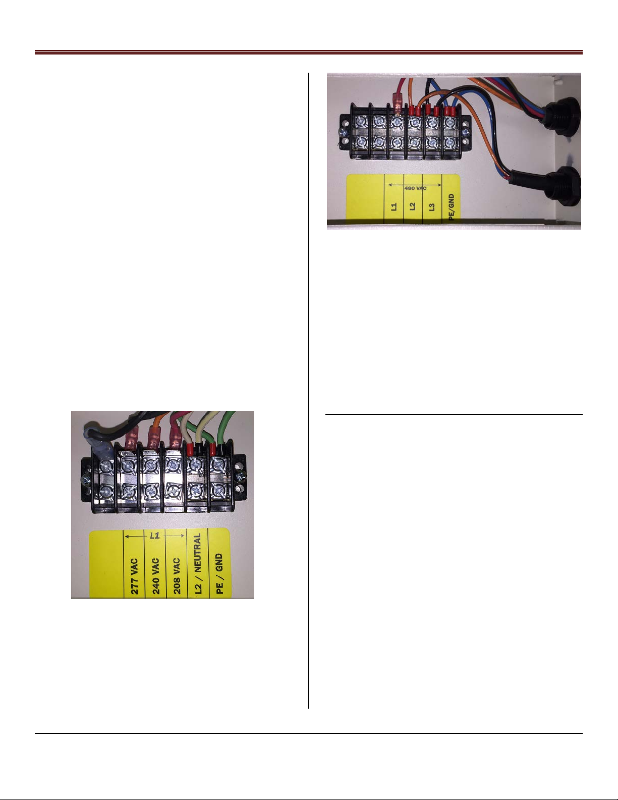
The M50 has a terminal electrical box at the bottom of the
unit, see Appendix 10. Notice the Black Jumper wire with the
spade connection must be moved from the blank terminal to
the 208, 240 or 277 VAC terminals see Figure 28.
1~ Electrical Power Connections, Figure 28
3~ Electrical Power Connections, Figure 29
CAUTION: The transformer was not designed to power other
equipment.
NOTE: The electrical access panels have screw holes to fit
most electrical box covers making it easy to install switches,
outlets, etc.
CAUTION: Line Voltage and Control wires must be routed
clear of any system components such as filter access doors
to prevent wiring chafing / electrical shorts.
CAUTION: Ensure line and control voltage wires are routed
away from terminal connections and control board.
Step 11 – Control Wiring
Note: Do not start unit till Step 15. See Appendix 2 for wiring
instructions.
CONTROL REQUIREMENTS
st
Input Cool Call “Y” (1
Variable Speed Fan, 0-10 VDC signal or no signal and
full speed; dipswitch 7 OFF
stage cooling call)
Three Phase Motors; 480 VAC, 50/60 Hz with an electrical
circuit breaker of 10 amperes each leg.
Winter/Summer mode; if fan to be used in winter
Freeze Protection relay; if needed
NOTE: The water control board provides 24 VAC (via
terminal RC) to be switched thru a dry contact back to
terminal Y.
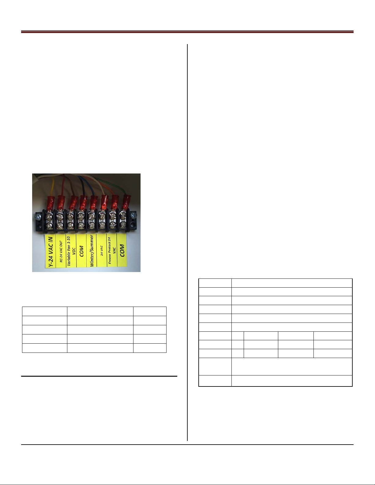
Eight Pin plug in Cable Connector on water control
board and wired to a wire terminal block
1. Y – Cool Call dry contact
2. RC - 24 VAC
3. Variable Speed Fan controlled by 0-10 vdc
4. Common
Page 17 of 63
Coolerado Installation
Unit Control
Thermostat TEC3620
Color
Y-24 VAC IN
FAN
Yellow
RC-24 VAC OUT
24V
Red
Variable Fan
CGL
Blue
COM
COM
Black
Dip switch
1
Power Failure Rewet; OFF less than 1 Hour, ON
2
Water Quality, OFF good, ON poor
3
Model Number, Factory Set
4
Model Number, Factory Set
Elevation
0
2000’ (610M)
4000’
6000’ (1830M)
5
Off
On
Off
On
6
Off
Off
On
On
On for Variable Speed Fan, 0 to 10 VDC
OFF = Single Speed Fan Setting (10 VAC)
8
On Freeze Protection mode see Appendix 8
5. Winter/Summer; winter mode when contact
closed. Allows fan to run without water
pressure. It initiates Freeze Protection relay,
this turns off the main water line, (if connected
to a solenoid valves), opens the water drain
line, and opens up the unit water solenoid valve
for 5 minutes. Closed contact or Winter mode
takes precedence over Winter/Summer Switch
on the Water Control Board. White light comes
on.
6. 24 VAC
7. Freeze protection relay.
8. Common
Control Terminal, Figure 30
2. Low and High water quantity, OFF plus 25%, ON
plus 50% over the calculated evaporation rate.
3. Model Number, in conjunction with 4; factory
setting.
4. Model Number
5. Elevation, in conjunction with 6.
6. Elevation
7. Auto Variable Fan, OFF 10 vdc, ON from AIN
8. Freeze Protection, OFF no freeze protection, ON
freeze protection, (requires connection to
solenoid valves by others).
If a variable speed thermostat is used, set control dip switch
setting 7 to the “on” position. This will vary the water flow
based on the amount of air flow. If dip switch 7 is set in the
off position, 10 VAC will be delivered to the fan motor control
wiring and it will run full speed whenever cooling is called for.
Dip switch setting 8 controls if freeze protection is on or off,
see appendix 8 for additional installation details. Freeze
protection allows the unit to be automatically pulled out of
service during a cold spell but keep the unit ready for cooling.
It should not be used for end of season shut down when
cooling is no longer needed for an extended period of time.
In some locations cooling is required all year round but still
may experience temperatures below 32
temporary shutdown to prevent breakage of valves or line.
Freezing will not harm HMX.
o
F and require
If using the recommended variable control thermostat model
TEC3620:
Thermostat Connections, Table 2
Step 12 – Control Board Set-up and Operation
Note: Do not start unit till Step 15.
CONTROL BOARD 8 DIP SWITCHES
1. Initiates the Wet Out cycle after a power failure
with two possible settings, OFF over one hour,
ON over four hours.
7
Table 3: Control Board Dip Switch Settings
Control Operation
See Appendix 2, 3, 4 and 5 for more information.
There are five (5) LED’s on the control board to indicate:
Page 18 of 63

Coolerado Installation
Soap Pump
Water Control Board
Transformer
Solenoid Valve,
Pressure Regulator
and Pressure Switch
Soap
Bottle
Power on: Green LED light
Water solenoid is powered: Clear light
Cool call: Yellow light
Flush cycle is on: Red light
Winter /summer: White light
The water control board has a fan speed potentiometer, (see
appendix 2). This is a single turn pot that controls the
maximum voltage going to the fan. If dip switch 7 is in the off
position the fan voltage can be turned between 0 and 10
VDC. If dip switch 7 is on, then this pot will proportionally
vary the voltage received at the water control board allowing
a maximum fan speed to be set. The factor setting is full
speed.
Note: If a three-speed fan is used the fan speed
potentiometer mentioned directly above may need to be
used to reduce fan speed, see appendix 10.
The water control board also has three switches mounted on
it for ease of maintenance, (see appendix 2):
NOTE: The thermostat should be mounted on an interior
building wall, free of drafts, and in an area unaffected by
heat producing machinery or appliances.
See Appendix 5, Thermostat Operation. For additional
information on the thermostat see Appendix 2, Control
Board and Wiring Diagram; Appendix 4, Coolerado
Thermostat Wiring; Appendix 5, Multiple Unit Control
Wiring and Appendix 6, Thermostat operation.
Step 14 – HMX Wet Out Logic
Note: Do not start unit till Step 15.
The unit is equipped with an automatic wetting system that
provides a significant boost to the heat and mass exchangers
wetting operations when the unit is powered up at initial
installation, for seasonal restart, or any other time that the
heat exchangers have dried out after the power has been
shut off.
1. WINTER switch allows the fan to be operated
through the cool call and AV fan but with the water
off. Putting in winter mode will also cause it to go
into freeze protection. The terminal connection
precedence over the board winter switch.
2. WETOUT momentary switch allows a maintenance
person to start a wet out cycle as long as there is a
Cool Call. A jumper across the Y and RC terminals
will cause a Cool Call.
3. PRIME momentary switch allows a maintenance
person to prime the soap pump by pushing it and
holding it till primed.
Step 13 – Thermostat
Note: Do not start unit till Step 15.
A standard thermostat can be used however most
thermostats do not have 0 to 10 VDC capabilities to drive the
Coolerado fully auto variable fan. For this reason, Coolerado
sells a variable speed thermostat.
NOTE: The efficiency of the Coolerado goes up significantly
as the speed is reduced, (4x at half speed), so variable speed
control is encouraged when possible.
Water and Soap System, Figure 31
Page 19 of 63
 Loading...