

Cool Energy EcoStore Heat Pump Water Heater
0 | P a g e
EcoStore - Air Source Heat Pump Water Heater
EcoStore

Cool Energy EcoStore Heat Pump Water Heater
1 | P a g e
INTRODUCTION
Thank you for purchasing this equipment which will give many years trouble free use with the correct installation
and care. In the unusual occurrence that problems occur with the installation or continued use please contact the
installer in the first instance to provide all the backup required to ensure these products meet the high standard
met by our products.
These
instru
ctions
are addressed
to both the
installer and
the final
user,
who
respectively
must install
and
use
the heat pump water
heater. Failure
to meet the
provisions
contained in this manual will
result
in the
cancellation
of the
warranty.
These
instructions include
essential
and important information for
safe
and proper installation, and
are an
integral part of the
product.
As a consequence,
all
technical documents
must
be
kept with care
and must always accompany
the product.
All
the
data and instructions contained
in
this manual refer
to the
current technological
level.
Please always refer
to the
instructions contained
in
this manual when installi
ng the equipment.
The operations described
in
these instructions
require
specialized knowledge, achievable
through a
comprehensive and proven professional training in system installation.
As a consequence,
we
recommend that you only perform the installation operations described
herein if you meet th
e
technical requirements listed
above.
The instructions are provided in schematic form; due to possible writing/printing
errors, and to
possible technical changes,
we decline all responsibility
as
to the
correctness
of the contents.
The diagrams used are
purely
INDICATIVE,
have
no
pretense
of
completeness
and
are
not intended
to
replace
the design.

Cool Energy EcoStore Heat Pump Water Heater
2 | P a g e
INDEX
1
GENERAL
NOTICE
..............................................................................................................................04
1.1
F
IELD OF US
E
.................................................................................................................................................................................04
1.2
PRODUCT NAME………………………..
..............................................................................................................................................04
1.3
SAFETY INFORMATION……………………….
.......................................................................................................................................04
1.4
C
ERTIFICATIONS
AND
MARKINGS
...............................................................................................................................................05
1.5
M
EANING OF
THE SYMBOLS USED HEREIN
................................................................................................................................05
1.6
D
ELIVERY AND PACK
AGING
.........................................................................................................................................................05
1.7
T
RANSPORT ……
.........................................................................................................................................................................05
1.8
M
EASUR
ING
.................................................................................................................................................................................06
1.9
T
EMPERATURE UNIT SHIFT
...................................................................................................................................................... .....06
2
TECHNICAL AND DIMENSIONAL
SPECIFICAT
IONS......................................................................
06
2.1
O
PERAT
ING PRINCIPL
E
.......................................................................................................................................................... .....06
2.2
E
NERGY EFFICIENCY
.................................................................................................................................................................07
2.3
H
OT WATER TEMPERATURE
.....................................................................................................................................................07
2.4
M
AIN COMPONENTS
...............................................................................................................................................................08
2.4.1
T
ANK
.........................................................................................................................................................................................08
2.4.2
HEAT PUMP UNIT
.......................................................................................................................................................................08
2.4.3
A
NTI-CORROSION PROTECTION
...............................................................................................................................................08
2.4.4
T
HERMAL INSULATION
AND COAT
ING
.....................................................................................................................................09
2.5
D
IMEN
SIONAL CHARACTERISTIC
S
............................................................................................................................................10
T
ECHNICAL
DATA TA
BLE
..........................................................................................................................................................10
3
INSTALLATION AND FIRST START-UP ..........................................................................................
11
3.1
H
YDRAULIC CONNECTION
......................................................................................................................................................11
3.1.1
H
YDRAULIC
SAFETY UNIT
.......................................................................................................................................................12
3.1.2
P
RESS
URE REDUCER
................................................................................................................................................................12
3.1.3
E
XPANSION TANK
...................................................................................................................................................................12
3.2
U
NIT FILLING
.........................................................................................................................................................................12
3.3
D
UCT
.......................................................................................................................................................................................12
3.4
E
LECTRICAL CONNECTION
......................................................................................................................................................14
4
USAGE IN
STRUCTIONS
...................................................................................................................
14
4.1
S
WITCH-ON
..................................................................................................................................................................................14
4.2
E
LECTRONIC CON
TROL
................................................................................................................................................................14
4.2.1
D
ISPLAY
...................................................................................................................................................................................14
4.3
O
PPERATING IN
STRUCTIO
N
........................................................................................................................................................16
4.3.1
O
PERATIONS BEFORE
TURNING ON
THE PRODUC
T
................................................................................................................
16
4.3.2
M
ODE
.......................................................................................................................................................................................16
4.3.3
H
EAT SOURCE
SHIFT
................................................................................................................................................................16
4.4
B
ASIC
FUNCTION
.......................................................................................................................................................................17

Cool Energy EcoStore Heat Pump Water Heater
3 | P a g e
4.4.1
W
EEKLY DISINFECT
FUNCTIO
N
................................................................................................................................................17
4.4.2
V
ACATION MOD
E
:....................................................................................................................................................................17
4.4.3
P
OWER ON AND POWER OFF
.................................................................................................................................................17
4.4.4
L
OCK AND UNLOCK
.................................................................................................................................................................17
4.4.5
Q
UERY FUNCTION
...................................................................................................................................................................18
4.5
S
E
TTING
.....................................................................................................................................................................................19
4.5.1
T
EMPER ATURE SETTIN
G
...........................................................................................................................................................19
4.5.2
C
LOCK SETTIN
G
........................................................................................................................................................................19
4.5.3
T
IMER
SETTING
.........................................................................................................................................................................19
4.5.4
C
ANCEL
....................................................................................................................................................................................20
4.5.5
D
ISINFECT MODE
.....................................................................................................................................................................21
4.5.6
V
ACATION MOD
E
.....................................................................................................................................................................22
4.6
C
OMBINATION BUTTON
..............................................................................................................................................................23
4.7
A
UT
O-RE
START
............................................................................................................................................................................23
4.8
S
CREEM AUTO LOCK
....................................................................................................................................................................24
4.9
E
RROR
...........................................................................................................................................................................................24
4.9.1
E
RROR CO
DE TROUBLE SHOOTING TABLE
.............................................................................................................................24
4.10
FAQ .............................................................................................................................................................................................26
4.11
H
YDRAULIC
SAFETY UNIT EFFICIENCY CHE
CK
.............................................................................................................................27
4.12
U
NIT
EMPTYING
...........................................................................................................................................................................27
4.13
R
ESTART AFTER A
LONG-TERM STOP
...........................................................................................................................................27
5
MAINTENANCE INSTRUCTIONS
....................................................................................................
27
5.1
G
ENERAL
......................................................................................................................................................................................27
5.2
F
ALSE ERRORS OF OPERP
ATION
..................................................................................................................................................28
5.3
V
ISUALIZED
TEMPER
ATURE
.........................................................................................................................................................28
5.4
HEAT PUMP UNIT MAINTENANCE
.................................................................................................................................................28
5.5
C
LEANING THE
ASPIRATION
AIR FILTER
......................................................................................................................................28
5.6
W
ATER
CIRCUIT
/
C
ONDENSATE DISCHARGE
............................................................................................................................29
5.7
A
IR CIRCUIT SUPP
LY
.....................................................................................................................................................................29
5.8
D
ESCALING AND LIME SCALE DEPOSIT REMOVAL
......................................................................................................................29
5.9
A
NODE
VERIFICATION
..................................................................................................................................................................30
5.10
R
EPLACE
AND/OR CONTROL THE
ELECTRICAL
RESISTANCE
.......................................................................................................31
5.11
O
UTSIDE CLEANI
NG
.....................................................................................................................................................................32
5.12
G
ENERAL NOTES
..........................................................................................................................................................................32
5.13
A
FT
ER-SALE
SERVICE
....................................................................................................................................................................32
6
MEASURES TO BE
ADOPTED IN CASE OF
MALFUN
CTIONS .....................................................32
7
INSTALLATION EXAMPLES…
..................................................................................................
34
8 COMMISSIONING SHEET AND SERVICE RECORD
..........................................................
35
Cool Energy EcoStore Heat Pump Water Heater
4 | P a g e
1
GENERAL
NOTICE
1.1
Field of
use
The heat
pump water
heater
for the production of hot
water is
only intended to be
used
for sanitary
water
heating,
without
exceeding
the
usage
restrictions
specified herein.
To
this
purpose
it must
be
hydraulically connected
to
a sanitary water delivery network. It
requires a
power su
pply to operate.
Never use
the heat pump for
any purposes
other than
those specified herein.
Any other
use is
to be
deemed
as
inappropriate and
forbidden.
The
manufacturer cannot be
held
responsible
for
any installation errors and inappr opriate
equi
pment
use.
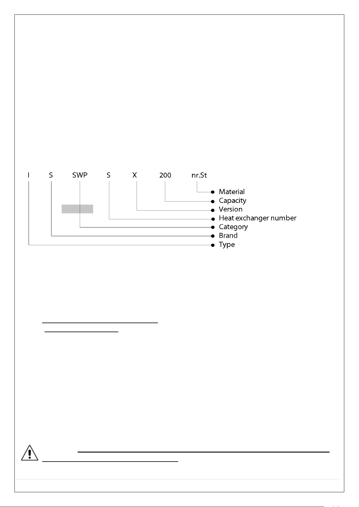
1.2
Product
nameplate – EcoStore CE-ES200 / CE-ES300
1.3
Safety Precautions
The purchaser shall take care
of the
installation. The Manufacturer shall
not be
liable
for
any damage
s
caused
by wrong installation and/or
noncompliance
with the instructions contained in this
use
and
maintenance booklet, and
in
particular
with
those prescribing
that:
• the
electrical connection must comply
with the
provisions specified
in the
relevant
para
graph;
• Uthe
supplied
nylon
electrical protectorsU must be properly installed;
• “Uthe
hydraulic safety
unit”U
must be
properly installed, intact
and
in good working order;
• installation and
maintenance
must be performed by qualified
personnel,
in
compliance with
the
regulations
in force;
• before st
arting any
maintenance
or repair
operations
on components containing any cooling
fluid, a qualified technician must remove
an
appropriate
amount of the
latter,
to
ensure
the risk-
free execution
of the
operations
in qu
estion.
The refrigerant
must be handled and
disposed
of
in
compliance with the relevant
regulations and
must not be
dispersed
into the environment!
(The R134a
refrigerant
is CFC-free,
not
flammable and
not harmful for the
ozone
layer);
• the
maintenance
regu
lations must be obse
rved;
• the equipment
must be installed
in
an appropriate
room (to
avoid
being
exposed
to frost)
• the
maximum overpressure, when using
the
tank, must be
respected;
• the
maximum
temper
ature, when usin
g the ta nk, must be respected
.
CAUTION! UFAILURE
TO
COMPLY
WITH
THE ABOVE PROVISIONS WILL RESULT
IN THEU
U
CANCELLATION OF ANY WARRANTY RIGHT.
This
equipment
complies
with the
provisions contained
in the
EEC
Directives
in force.
Cool Energy EcoStore Heat Pump Water Heater
5 | P a g e
1.4
Certifications and
Markings
The
verification
has
been performed
with
reference
to the following
technical standards:
UNI EN
16147;
EN
12102;
EN
60335-1;
EN
60335-2-21;
EN
60335-2-40;
EN
55014-1;
EN
55014-2;
EN
61000-3-2;
EN
61000-3-3;
EN
50366.
1.5
Meaning of the symbols used
herein
Symbol
Meaning
Failure to comply with the provision in question may result in injuries and/o
r
damages
to people,
objects, plants or animals.
1.6
Delivery and
pack
aging
The
heat pump water heater
is supplied
in an environment-friendly and
easy
to handle cardboard
packaging
with protective
inserts. Make sure
that the
packaging
material is
disposed
of properly
in
compliance
with the
environment-related regulations
in force.
S
hould the heat pump for
sanitary
water show any clear
damages, absolutely
avoid mounting or
installing it.
Immediately
inform the supplier.
1.7
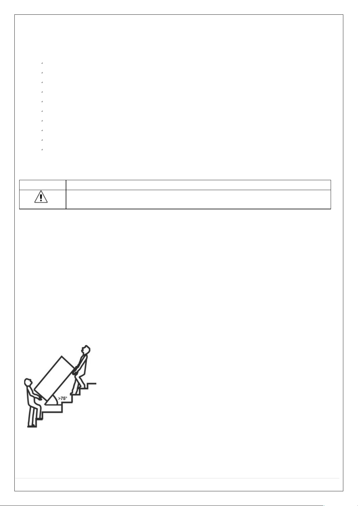
Transport
When
storing and transporting it,
always
keep the heat pump water heater vertical
(straight)
in its
original packaging.
For
short
stretches
it
can
be
inclined
by
45°,
provided utmost
care is taken
when
transporting it.
Due
to the forward
inclination,
when usin
g forklift
trucks
or other
means
of
transport proceed sl
owly and fasten the equipment to prevent it from
tipping.
After
transporting the equipment in
inclined
position,
before starting
it you
need to wait for about 3
hours,
to
ensure
the appropriate settling of the
lubricating oil in the cooling circuit
and avoid
damages.
Position the heat pump,
after removing the packaging and the bracket
supplied
for
transp
ortation.
For short moves use
the
special handles situated
on the
side
part of the pr
oduct.
Cool Energy EcoStore Heat Pump Water Heater
6 | P a g e
1.8 Measuring
The measuring units used in this manual for the relevant physical magnitudes are those of the
International
System(SI).
1.9
Temperature unit
shift
Press
ENTER
for
3 seconds
to
unlock
the buttons.
P
ressing
the
E-HEATER
key for 10
seconds
they can shift the temperature from
display unit
from
‘°F’
to
‘°C’ or
from
‘°C’
to ‘°F’
The
default
is ‘°C’.
When
it
is sh
ifted
to
display
‘°F’ , it still will
display
‘°C’
while it operates spot check.
2
TECHNICAL AND DIMENSIONAL
SPECIF
ICATIONS
2.1
Operating
principle
The air-water
heat pump
uses
the
energy
of the air existing in the environment.
The
air required fo
r
the proper operation of the
heat
pump
can be
drawn from the
outside through a window
(mini
mum
temperature
-20°C)
or from the surroun
ding environment
or from other
environments
through ducts.
The
air drawn from the environment
is sucked
through a fan and the heat
existing
in air
is
absorbed
during the
passage
in
a heat exchanger (evaporator).
In the
evaporator
the
heat taken
from the
air
is
caused
to evaporate at low
pressure
by the refrigerant (the working fluid in the refrigerant circuit,
is as in a household fridge).
The vaporized
coolant is
sucked
by a
compressor
and raised to a
higher level of pressure (as
in
a bicycle
pump)
and temperature.
In
a second heat exchanger
(condenser)
the higher
temperature
heat
is absorbed
and
transferred
to the
water;
this
way
the

Cool Energy EcoStore Heat Pump Water Heater
7 | P a g e
vaporized
refrigerant fluid
switches back
to the liquid
state as a
consequence
of thermal
dissipation.
The
liquid
refrigerant, fl
owi
ng through a choking component
(expansion valve), undergoes
a low
pressure expansion and, after
returning to the
evaporator,
it
can again draw heat
from the
surrounding
environment.
The
hot
water heat
pump
operates at ambient temperatures ranging between
-20°C and +43°C.
The hot water heat pump is a
connection-ready
equipment whose function
is
heating drinkable
water;
it
basically consists
of the water tank and of the
refrigerant,
air and water circuit
components,
as well
as
of
all
the co
ntrol,
adjustment
and
monitoring
devices required
for
automatic
operation.
> Use of the environment energy
Refrigerators, washing machines,
heating
systems and
other equipment/electric
appliances
generate
heat that in most
cases
is not reused. Instead
of being
dispersed
into the environment, generating
pollution, the hot air in question can suitably be
used
to heat sanitary water: a
sensible
and
environment-friendly
solution.
An
important benefit
is
the
air
dehumidification
resulting
from
heat suction, decreasing
the
degree
of
humidity in
cellars and
laundries.
This has
two
beneficial effects: environment
prote ction
and
production of
cheap
hot
sanitary
water.
2.2
Energy efficiency
> Free energy
The necessary energy
for the heating of
sanitary
water
comes
for 2/3 from the air and 1/3 from the
electric
power supply.
> Coo
ling through
the heat pump for
hot
sanitary
water
After heat subtract
ion,
the lower-temperature output air can be
used
during
summer
to cool th
e
environment where
the
heat
pump
is
installed.
This provides a
double
benefit,
while
ensuring
optimum
energy
efficiency.
> multi
use of
energy
The heat pump can be beneficially installed in stores, workshops, commercial, residential
applications etc. to get hot
sanitary water and,
if needed, cooled air.
2.3
Hot water
temperature
Setting water temperature
target
range:
38÷
65°C.

Cool Energy EcoStore Heat Pump Water Heater
8 | P a g e
Using renewable energies and ensuring
optimum
energy efficiency,
the
heat
pump
provides an
environment-friendly
and efficient
solution to
heat water throughout the
year.
2.4
Main
components
2.4.1 Tank
The tank consists
of a water-tight Stainless Steel AISI316L
cylindrical inner vessel.
2.4.2
Heat pu
mp unit
The
refrigerant
circuit
is
located
in the upper
section
of the
water heater and co
nsist of:
•
Refrigerant
fluid R134a;
•
Rotary
compressor;
•
Thermostatic expansion
valve;
•
Solenoid valve
for the
de-frosting
cycle;
•
Combined filter, drier and collector
of the
refrigerating
circuit;
•
High-powe r blade
evaporator;
•
Electronic axial
fan;
•
Average-sized Cu cooling
pipes;
•
Thermal exchanger co oper
pipe wounded
around
the inner vessel ( in
this
way a
contact between
the
refrigerant gas
and
the
drinkable water
is
impossible);
•
Condensation drain plastic pipe.
2.4.3
Anti-corrosion
protection
The
protection
against corrosion
is
performed by
an
integrated
electronic
anode.
Data:
Electronic
• Feeding
90 - 253Vac 50 - 60Hz
•
Maximal
absorpti on 3
•
Maximal
output voltage 20Vdc
•
Maximal
output current 15mAdc
• Working temperature
-10 – 85°C.
•
Protection
level IP44
• Size 85x55x26mm
Electrode
•
Protection
electrode
activated
titanium diam. 3mm
• Fastening 1/2”
•
Screwi
ng up max.
25
Nm
•
Working
temperature
-10 – 100°C.
Co
nnection
•
Power
cable double
insulation cable tmax 105°C.
•
Protection
cable flat
cable 2x0,50mm red/black (red cable:
electrode)
•
Electrode
connection
bush
diam. 3mm
• T
ank
connection
eyelet
diam.
5mm.
Cool Energy EcoStore Heat Pump Water Heater
9 | P a g e
Positioning
All fastening, connection and
maintenance operations must be
performed when the device
is not
powered.
Be sure
that the
device has a
proper
position, far
away
from water, direct
heat sources,
etc.
Do not open the container of th
e
device,
inside there are no sp
are
parts.
Do not invert the connections
electrode-tank.
2.4.4
Thermal insulation and
coating
Thermal insulation
is ensured
by a highly
biological, CFC-free
rigid
polyurethane
foam
(PUR)
coating.
The
full
compressed foam coating allows
to
minimize energy
losses.
The external coating
is made
of a soft PVC material.
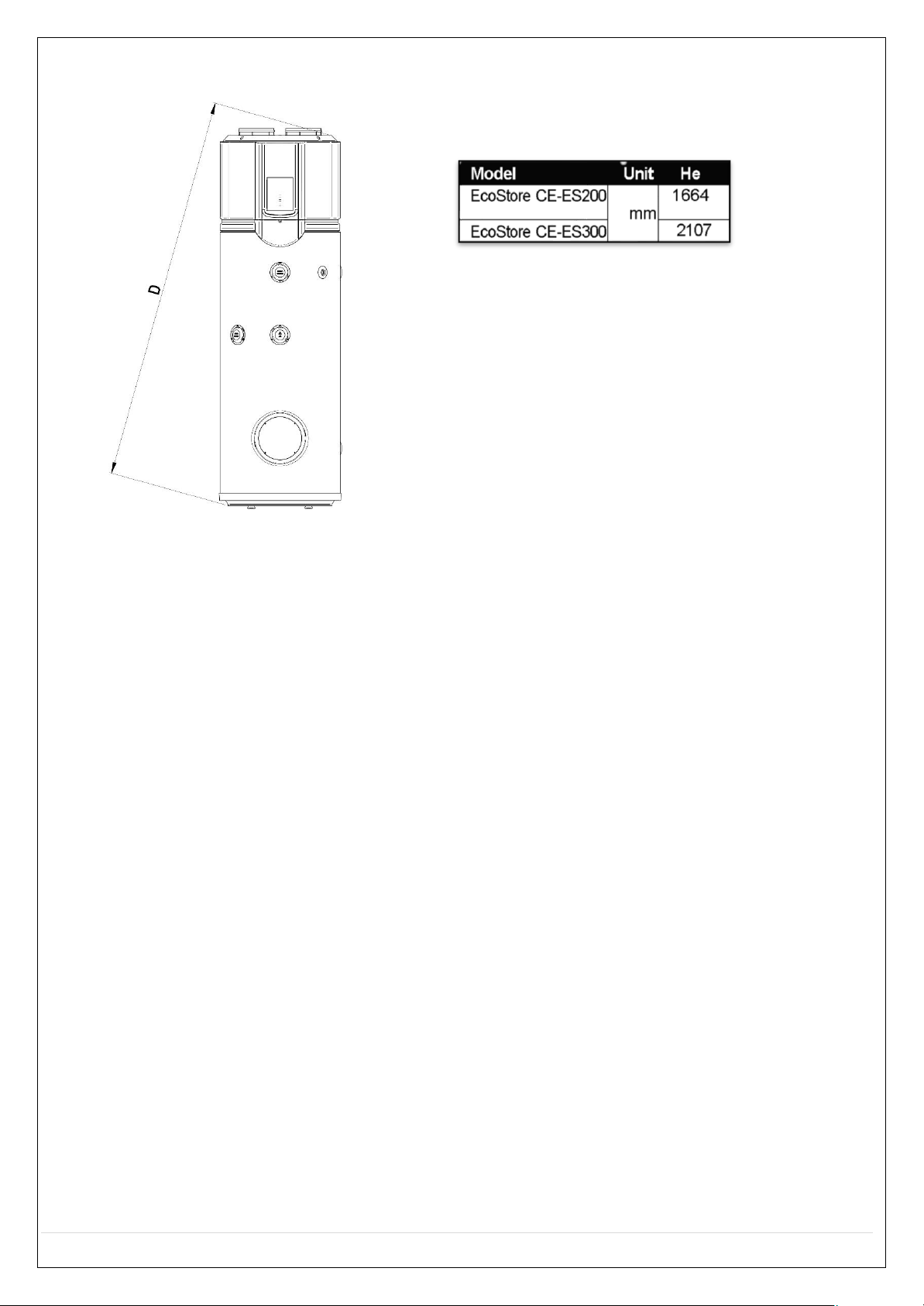
2.5
Dimensional char
acteristics
The technical and
dimensional characteristics
of the equipment
are
indicated
in
Fig.
1.
The electrical characteristic data
of
each
model
can be
found on the equipment itself.
Heating exchanger su
rface:
Model
Unit 0 H
EcoStore 200
mm
650
1586
EcoStore 300
2107
Model
Unit
Lower
heating
exchange
r
EcoStore 200
m
2
0.6
EcoStore 200
1.3
Cool Energy EcoStore Heat Pump Water Heater
10 | P a g e
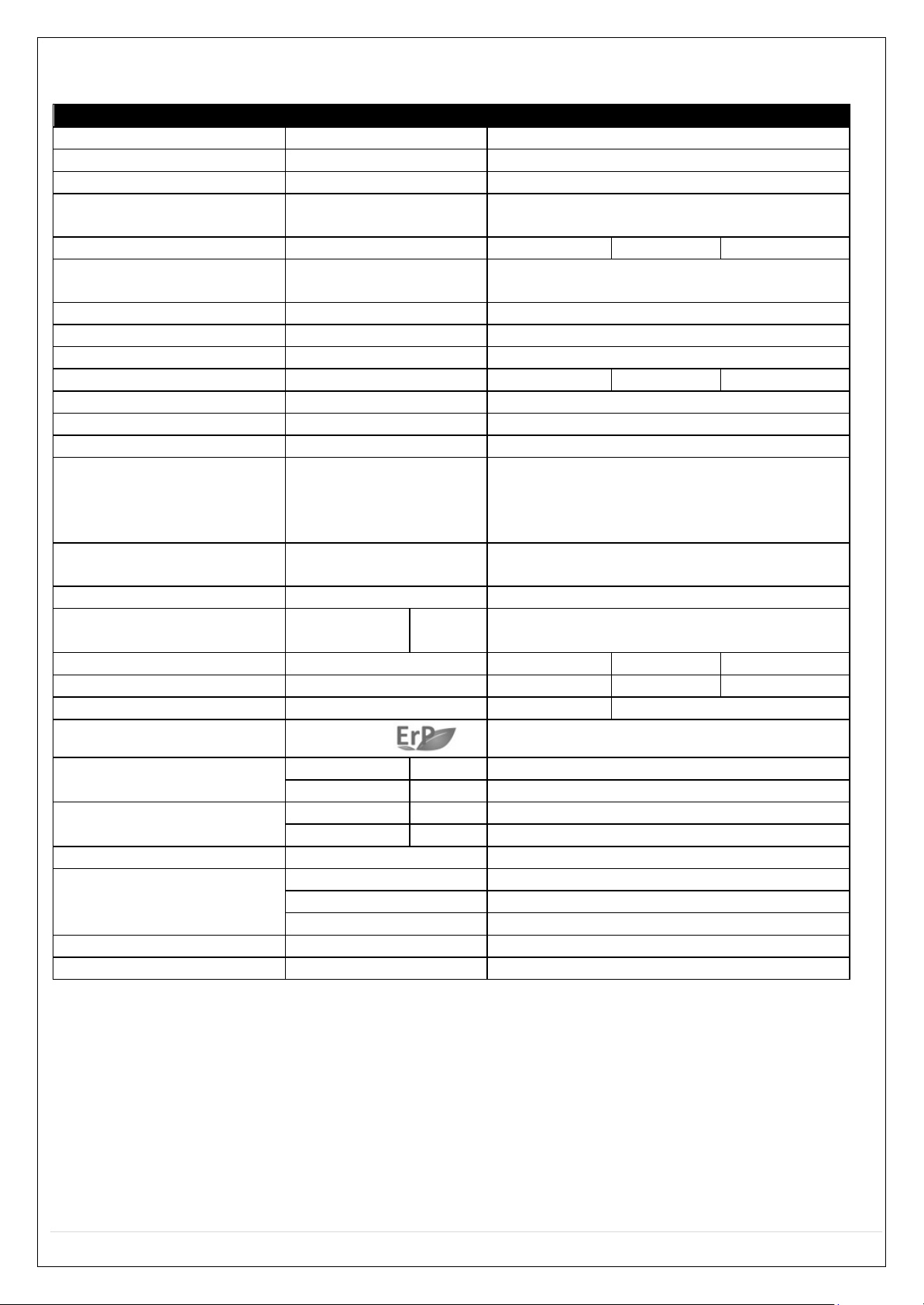
Technical data
table
Model
EcoStore 200
EcoStore 300
Type
Air Source Heat Pump
Use
Water Heater
Temp.
Ԩ
Standard 55°C ( 38°C bis ~ 65°C)
Storage
material
(DIN
4753)
AISI 316 / EN
1.4404
Storage size L
200
300
Insulation
thickness
mm
B2 / DIN
4102
50
Power su
pply
Ph-V
-Hz 1 –
230 – 50
Ambient temperature
Ԩ
-20°C
min /
max.
+43°C
Noise
level
dB(A)
53
Refrigerant type / quantity
kg
R134a/1.02
R134a/1.2
Refrigerant design pressure
MPa
3.0/1.2
Tank design
pressure
MPa
0.6
Control
Electronic
Program
Economy
E
-Heater
Vacancy
Disinfect
Protection
TCO1, TCO2,
de-frosting automatic
Air
flow m3/h
414
Compress
or
Input
kW
0.62
COP
A15/W1
5-60
2,76 3,1
COP A 15/W
15-45
3,86
4,34
ErP Test
Profile
L
XL
Erp Energy Class
Class
A+
Fan
Input
W
68
r/
min
620/530/465
Water pipe
Rp
1"
Rp
1"
Condenser Diameter
Copper 0 8x0,5
E-heater
No.
1
Material
Nicolay
800
kW
0.9
Tank protection
Electronic Anode
(DIN
4753)
Electrical protection IP21
Cool Energy EcoStore Heat Pump Water Heater
11 | P a g e
3
INSTALLATION AND
FIRST
START-UP
(qualified personnel
only)
CAUTION!
•
The installation
room must be 20 m3 or larger and have
suitable
air e
xchange and not be subject
to sub zero conditions.
• The equipment must be installed in
compliance
with the national installation
regulations.
•
Operations involving
the hot water heat pump
must
only be
performed
by competent /
qualified personnel!
•
Observe the safety regula
tions.
• The
installation environment,
electrical
and
hydraulic systems of
the equipment m
ust comply
with local regulations in
force.
•
You need
to
install
the
equipment
at the
prescribed distance
from the
room walls
and
ceiling, to ensure easy
maintenance.
•
The surface on
which the equipment is to be
installed must be able to
bear
its weight.
•
The equipment ventilation
openings
must not be obstructed.
•
The chosen environment must
be
suitable
for the
equipment IP degree,
in
accordan
ce
with the
regulations in
force;
•
The ambient temperature
(or the
temperature
of the input air)
must range between
-
20°C and +43°C.
• If
possible, install the equipment in a room allowing to exploit the
excess
heat
generated
by
tumble-driers, refrigerators, freezers,
etc.
• Air
must be neither
excessively purified nor too
contaminated with
dust.
•
There must be a
suitable drain connection to discharge cond
ensa
tion from the unit.
CAUTION! UThe equipment is
not
intended
to be
used
by any
persons ( including
children
)U
U
having reduced sensory
or mental faculties, or lacking experience or knowledge,
unless
theyU
U
are under the supervision
of a
person in charge
of
their safety, or they have received
properU
U
instructions regarding equipment
usage.
Children must
be watched to ensure
that
they don't play with the
equipment.
3.1
Hydraulic connection
Installations must conform to local
regu
lations in force. We recommend the integration of a
magnetic filter for the cold feed water supply. The link
pipes
(hot water,
recycle,
in-out
exchanger)
must
be perfectly isolated according
to the
energy norms
in
order
to avoid
heating
dispers
ions.
We recommend
that you install the equipment
close
to the
main
hot
water
drawing point, to prevent
heat
dispersions
along
pipes,
and if possible, near a drain, for
easier
emptying and condensate
discharge
Cool Energy EcoStore Heat Pump Water Heater
12 | P a g e
3.1.1
Hydraulic safety
unit
(manda
tory)
You
must install a
hydrauli c safety
unit (Supplied in G3 Kit)
complying with
EN 1487
or with
equivalent local standards
in
force;
•
Check
valve;
•
Check valve
control de
vice;
•
Safety valve;
•
Hydraulic load
interrupting
device.
The above components are required to
safely
run the supplied equipment. The rated calibration
pressure
of the hydraulic
safety
unit must be of
0.6 MPa
(6
bar). Pay
attention while installing the
hydraulic safety
unit,
avoiding forcing or altering it. Water may drip from the hydraulic safety un
it
discharge connector (see paragraphs
“USAGE INSTRUCTIONS
(user) - Water dripping from th
e
hydraulic
safety unit”).
This
opening must
be left
exposed
to the atmosp
here.
You
need to install a
discharge
pipe, with a constant downward
slope, in a
condensate-
and
ice-free area. There
must be
no
obstructions
in the
pipe,
to
avoid overpressures.
3.1.2
Pressure
reducer
Should the network
pressure exceed 0.6 MPa
(6
bar),
you need to install an appropriate pressure
reducer upstream
of the
hydraulic safety unit,
ensuring
the
indicated operating
range.
3.1.3
Expansion
tank
To prevent any
overpressures
that might
damage
the equipment, frequently triggering the safety
unit and causing water
dripping,
Uit is mandatoryU that you install an adequate
expansion
vess
el.
Install it in
accordance
with the instructions provided by the manufacturer. The expansion
tank is
required
to
keep pressure
constant and avoid harmful
pressure shocks
or
accidental overpressures.
3.2
Unit
filling
WARNING: USwitching on the equipment when
it
is
not filled with water will seriously
damageU
U
the refrigerating units and the electrical
heating element.
WARNING:
UIn the
presence
of water with a
hardness degree >20°TH (where 1°TH=Frenc
hU
U
degree=10mg CaCo3/l)
it
is
mandatory that you install a
softener
to
reduce
limestoneU
U
scaling inside
the
boiler
and
keep
the
electrical resistance
and the
hydraulic safety
unit inU
U
good
working
order.
To
fill the equipment,
you need to:
•
open
the
main water supply
or the equipment
water supply valve;
• open a hot
water
tap
(e.g. ba
throom,
wash basin, etc.)
to allow the water to flow out; when the
water
outflow from the tap
is
constant
the equipment will
be full;
Cool Energy EcoStore Heat Pump Water Heater
13 | P a g e
•
check
that
there are
no
leaks
from the
various hydraulic
connections;
UNote******
We
recommend
that
you flush
the pipes before connecting the unit
Only proceed
with the
electrical connection after
performing
this
operation
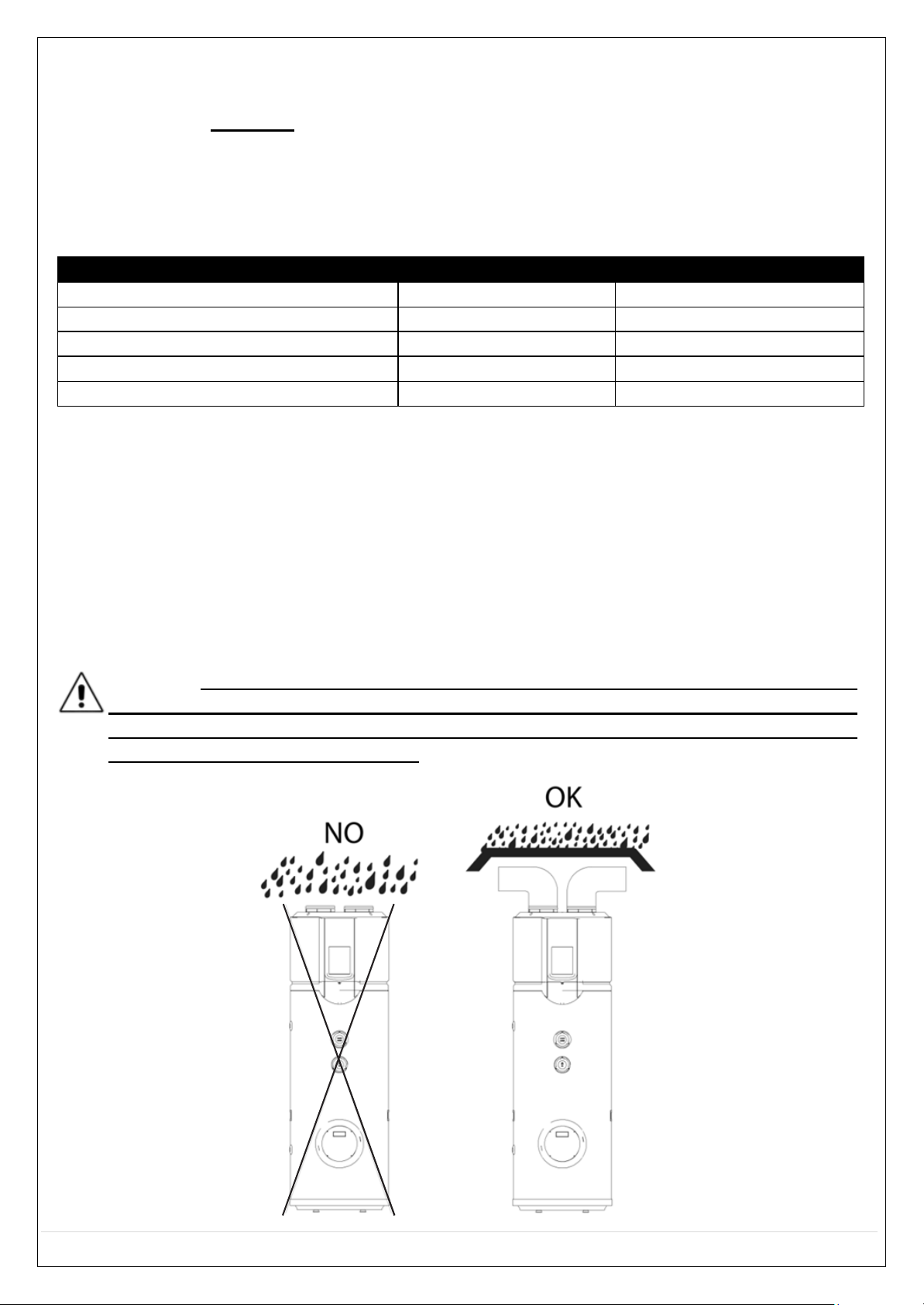
3.3 Duct
DUCT
ROUND
DUCT
RECTANGLE
DUCT
Dimension (mm)
190
190x190
Straight-li ne pressure
drop (Pa/m)
≤2
≤2
Straight-line
length (m)
≤5
≤5
Bent pressure
drop (Pa/m)
≤2
≤2
Bent’s
qty.
≤5
≤5
•
Too much resistance of duct will
decrease air-flow-rate,
which will lead to capacity of
unit decreased.
•
T
otal duct length ideally
should be
no
more
than 5m and 3 x 90 degree bends or the
maximum static pressure should be
within
25Pa.
•
For
unit air outlet with duct, when unit operating,
condensate
will be generated around
outside
of duct.
please pay
attention to the
drainage
work, we
suggest
to wrap the thermal
insulated layer around outside
of the duct.
• It
is recommended
to install the unit in the indoor
space,
it
is
not allowed to install the unit
at the
rainy space.
WARNING: UIn case of rain entering
to
internal components of the unit, the component
mightU
U
be damaged
or
causing physical da nger.
In
terms
of
the unit connect with duct reaching
toU
U
outdoor, a reliable water-resistant measure must be conduct on the duct,
to
prevent
waterU
U
from dropping into in
ternal of the unit.

Cool Energy EcoStore Heat Pump Water Heater
14 | P a g e
3.4
Electrical connection
WARNING:
UThe
equipment is
already
factory-wired
and
is equipped
with a plug for theU
U
connection to an outlet ha
ving appropriate electrical characterist
ics.
U
Verify
that the
mains voltage complies
with the
value specified
in the
labe l applied on
theU
U
equipment, and
that
the mains can supply
a sutable pressure and flow.
To disconnect
the equipment from the
mains
you
need
to
use a
two-pole
switch
complying with the
EN standards
(contact opening 3mm, preferably equipped with
fuses).
The connection must be
established by inserting the plug into the appropriate outlet, that must comply with the regulations
in force.
WARNING: USwitching on the equipment when
it
is not filled with wa
ter will seriously
damageU
U
the
refrigerating units and the electrical
resistance.
WARNING:
UIf
the supply cable is
damaged,
it
must be replaced by the manufacturer or by it
sU
U
technical support service,
or
anyway by a person having a s
imilar
qualification,
to preventU
U
any
risk.
4
USAGE INSTRUCTIONS
(User)
4.1 Switch-on
WARNING: UBefore switching on the equipment, always
verify the correctness of the
electricalU
U
connection; also check
that the tank
is
filled with water, to
avoid seriously damaging
theU
U
refrigerating
unit
and the electrical
heating elements.
4.2
Electronic co
ntrol
The
heat pump water
heater is
equipped with an
electronic
regulation
system
for the management
of the
temperature and
of the
complementary E-Heater.
4.2.1 Display

Cool Energy EcoStore Heat Pump Water Heater
15 | P a g e
Water Temperature setting

Cool Energy EcoStore Heat Pump Water Heater
16 | P a g e
4.3
Operating instr
uctions
4.3.1
Operations before turning on the
product
• When the product
is
turned on for the first time, all indicators on the UI will turn on for 3
seconds,
and in the
same
time an
acoustic
sound will be
heard.
After a minute without any
other
operation,
all
buttons are
blocked apart from
UNLOCK
button.
Press
it for 3
seconds
to
unlock
the buttons.
• When the tank will be full and all the
settings
set,
press
the ON/OFF button and start the
equipment.
• When the equipment is working, if no operation is going to be done and there is no
malfunction for 30
seconds,
the
display
will be locked apart from the error
codes
and alarm
li
ghts.
Press any
button to
unlock
the display.
4.3.2 Mode
Modes
will
be automatically selected
by unit.
Manually mode
selection
is
unavailable. Se
tti
ng
water temperature
target
range: 38
- 65°C. Max 55°C is recommended for good efficiency.
E-heater
running
ambient temperature range:
-20 - 45°C.
Heat
pump running
ambient temperature range:
minus7 -
45°C.
Ambient Te
mp.
TA<-7
-7≤ TA<-2
-2≤TA<2
2≤TA<7
7≤TA<35
35≤TA<43
Max.
Temp.
(Heat pump)
-
42
47
55
65
60
Max.
Temp.
(E-heater)
65
65
65
65
65
65
4.3.3
Heat source shift
The
default
heating source is heat
pump.
• If ambient
is
range out of heat pump,
heat pump will stop r
unning, the unit will shif
t
automatically to activate
E-heater
and show the icon LA ( );on the display, then if the
ambient
temperature goes
into the running
range
of
heat
pump
again,
it will
stop E-
heater
and
shift
automatically
to
heat
pump
again, and
the
icon LA( )
will
be exti
nguished.
• If the target setting water temperature is higher than
Max
temp (Heat
pump),
the unit
will
activate
heat pump firstly to the
Max. temperature,
then stop heat pump,
activate E-heater
to
continuall y
heat water
to the target temperature.
• If
manually activate
the
E-heater
running mode when heat pump running,
E-heater
and heat
pump will work together until the
water temperature gets
to target
temperature.
So
if want
to
heat quickly, please
manually activate
E-heater.
NOTE: E-heater
will
be activated once
for the
current heating
progress,
if want to
apply
E-heater
again, please push
.
• If
system occurs some malfunctions,
error
code "E7" and
will be shown on the
display, then
heat pump will stop running, and the unit will activate automatically
E-heater as
the backup
heat source,
but the
code "E7"
and will be shown until power off.
Note: If only the electric element is used
as
a heating
source,
only one part of the cylinders
content will
be heated; the
water temperature must be set at a higher
value
that the
one
for the

Cool Energy EcoStore Heat Pump Water Heater
17 | P a g e
running of the
heat
pump.
•
Defrosting
during
water-heating.
In heat pump running
period,
if the evaporator frosted in lower ambient temperature, the
system
will
defrost automatically
to
keep effective performance(circa 3~10
min.).
At defrosting
time,
the
fan
motor will
stop,
but
compressor
will still run.
•
COP
The
COP (Coefficient of Performance)
varies when the environmental temperature varies.
Normally,
lower is
the
environmental temperature, higher
will
be
the
water
heating.
• When the environmental temperature is inferior to
2°C,
the heat pump and the electric
element
work together
order
to
reach
the
planned temperature
(see
the chart).
4.4
Basic
function
4.4.1
We
ekly disinfect
function
Under disinfection mode unit immediately start to heat water up to
65°C
to kill the potential
legionella
bacteria inside
water of tank, “ ” icon will light on the
display screen
during
disinfection
;
Unit will quit
disinfection mode
if
water temperature
is higher
than
65°C
and extinguish
“ ”icon.
4.4.2
Vacatio n mo
de:
After
pressing "Vacation"
button, Unit will
automatically
heat water to
15°C
for the
purpose
of energy
saving
during
vacation
days.
4.4.3
Power On and power
Off
Press “ON/OFF”
( ) button after all the above have finished and the
system
will run
as
the
setti
ng. And simply press
the
same
button to
stop
it.
4.4.4
Lock and
unlock
In order to prevent wrong
operation, a special lock
function
has been design.
If there
is
no operation
for 1 minute, the unit will
be locked automatically,
and display
the
lock sign (Lock
indicator lights
up)
.
When
the unit is
locked,
no
keys can be operated.
Pres s for 3
second
to
unlock
the bu
tton

Cool Energy EcoStore Heat Pump Water Heater
18 | P a g e
4.4.5
Query
function
For the
convenience
of maintenance and debug, query function is available by
Press 2 buttons
together. +
,
then
system
running
parameters
will be shown one by one
with following sequence
by
each pushing
of “ “o “ ”
button.
N.
TEMP./DASYS
EXPLENATION
1 t 5 U T
emp.
T5U
2 t 5 L Temp.
T5L
3
t 3 T
emp.
T3
4
t 4 Temp.
T4
5
t P Temp.
Tp
6
t h Te
mp.
Th
7
C E Current Com
pressor
8 1
Last
error
9
2
Previous 1st error or prot
ection
code
10 3
Previous 2st error or prot
ection
code
11
Software
number

Cool Energy EcoStore Heat Pump Water Heater
19 | P a g e
4.5 Setting
4.5.1
Temperature
setting
The
temperature displayed
is
the
water temperature
in the
upper
part of tank.
Method for
temperature
set:
Press
the button to increase the
temperature, press the button to
decrease.
Confirm
setting.
4.5.2
Clock
setting
The clock
is for a 24-hour system and the initial time is
00:00. To make
a better
use
of this unit,
it is
recommended
to
set
the time for
accurate local
time. Every
time powered off, the
clock
will be reset
to initial time 00:00.
Method for time set:
Press
button for 5 sec to enter clock
setting. Then icon will be
lightened and the hour
value
of
clock
will
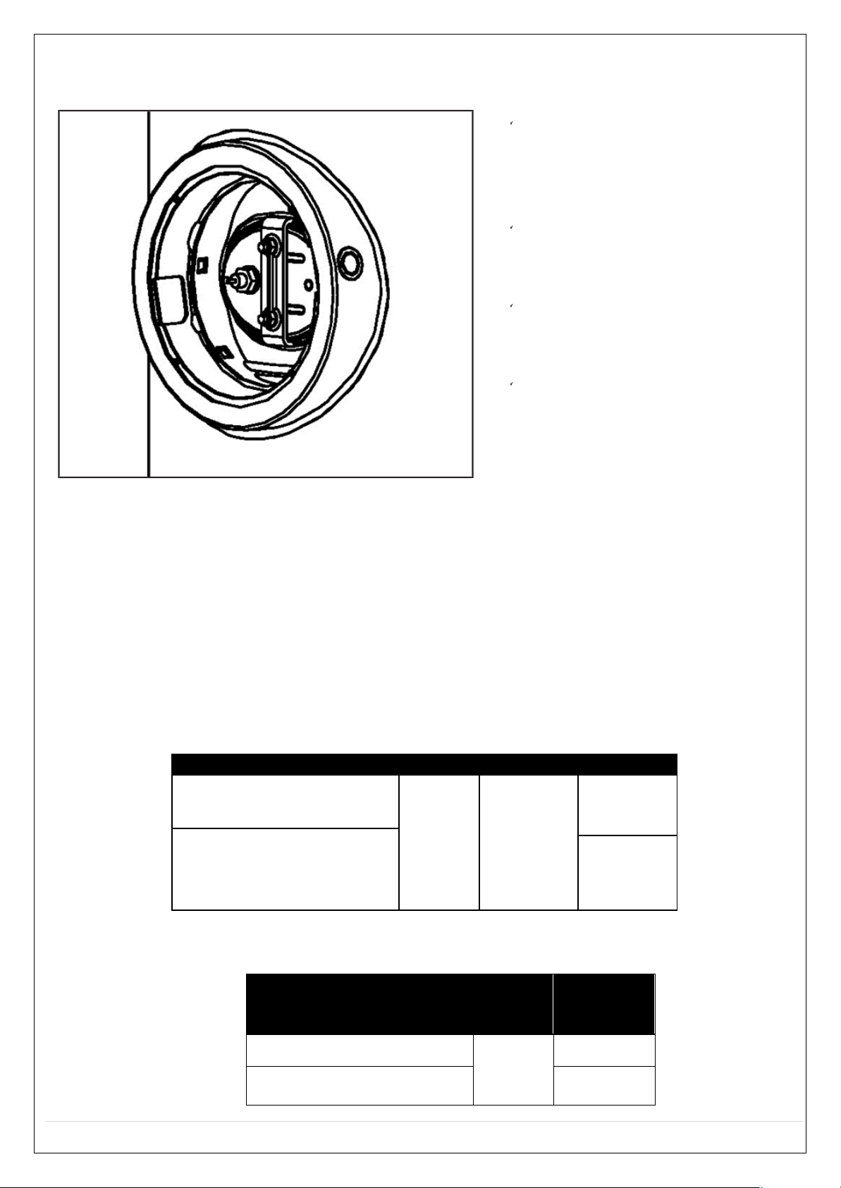
flash
slowly
Set
the hour
value
of
clock.
Confirm
the hour setting.
Then
the minute
value
of
clock
will
flash
slowly.
Set
the minute
value
of clock.
Confirm
the minute se
tti
ng
and
quit clock
setting.
4.5.3
Timer
setting
User
can set up running start time and stop
time on a
specifically
by the timer function.
The
least
numbers
of timer is
10
minutes.

Cool Energy EcoStore Heat Pump Water Heater
20 | P a g e
Method for timer set:
E
nter timer setting.
Select
timer
( )which needs
to be
set. The timer icon will flash slowly if it is
select
ed.
Confirm
the
selected se
tti
ng
timer.
Then
will
be lightened .
Then
the hour
value
of timer will
flash
slowly.
Set
the hour
value
of
timer.
Confirm
the hour
value
of
timer. Then
the
minute
value
of timer will
flash slow
ly.
Set
the minute
value
of timer.
Confirm
the minute
value
of
timer.
Then
ON or
OFF
icon following the setting timer
will flash
slowly.
Set
the
action (ON
or
OFF)
of the timer.
Confirm
the
action (ON
or
OFF)
of the timer.
ON
/OFF
ON
OFF
The
display
screen
will automatically display
different value at by different action. It
will
display
the last set
temperature and icon
if the action
is ON,
and will display-- if
the action is OFF.
Set
the water temperature of the se
tting
timer.
Confirm and complete
the timer.
Then
repeat
this process
to
set another
timer.

Cool Energy EcoStore Heat Pump Water Heater
21 | P a g e
Method for
cancel
timer setting:
Enter
timer se
tting.
Select timer ( )which
needs
to be
cancel.
The timer icon will
flash slowly
if it
is
selected.
Confirm
to cancel the timer. Then repeat
selecting
timer and
cancelling.
If the timer has
not been
set,
when
press
button the
display will show
.
After complete
canc
elling
timer, press button fo
r
3sec
to quit timer
cancelli
ng.
Method for
check
timer setting:
Select
time ( )which
needs
to be
checked.
The
timer icon will
flash
slowly if it
is
selected, and the timer
action(ON
or
OFF)
and
set clock will be
shown.
If the action
is ON,
target temperature will be shown. And if the
action
is OFF,
icon will
be shown.
Press
button for
3sec
or no
button
pressin
g for
30sec
to quit timer checking.
If there is
confliction
between Timer and
Manually
ON:
1. The
moment of
Manually ON has
priority;
2. The
moment of timer
OFF has
prio
rity;
4.5.4 Cancel
To cancel setting, quit setting,
clear al
arm,
etc.
press
button.
To clear alarm
buzzer, need to
press
same
button for 1sec.

Cool Energy EcoStore Heat Pump Water Heater
22 | P a g e
4.5.5
Disinfect
mode
Manually
turn on
disinfect
function:
Icon will fl
ash
Confirm
manually activate disinfec
tion
function, then the unit will heat up water to
65°C at least for
disinfection.
Disinfect Clock
Setting:
Press
button for
3 sec. To enter
in
the hour settings of Disinfect moda
lity.
The
icon
flashes,
the icon lightens
and
the hour indicator st
arts
to
flash slowly.
Set
the hour
value
of clock.
Confirm the hour setting.
Then
the minute
value
of
clock
will
flash
slowly.
Set
the minute
value
of clock.
Confirm the disinfect clock setting and qu
it
out.
Unit will automatically st
art
disinfection function at the
above-set
clock
every 7 days.
If
user
don't
set disinfect
clock,
unit will automatical ly start disinfection
function at
23:00 every 7 days.
If unit is
OFF
or
under
disinfe
ct
mode, press
will
lead
to
show
on the
display.

Cool Energy EcoStore Heat Pump Water Heater
23 | P a g e
4.5.6
Vacation
mode
Method for
Vacation mode setting:
Enter Vacation setting. Icon
wi
ll
flash.
Icon will
be
lightened.
will
show
the
last
setting
vacation
days.
Set vacation
days.
The days range is 1~99
days.
Confirm
Vacation setting and quit out. The
unit will
immediately
go into Vacati
on mode.
In vacation mode, the setting target water temperature is
15°C as
default and will
show the
remaining
vacation days.
On the
last
day of
vacation,
unit will automatically start disinfecting function,
and automatically reset the target temperature to the last one before
vacation. If unit
has
already
been under vacation mode or
OFF, press
will lead to
show
invalid icon on th
e
display.
4.6
Combination
button
ICON DESCRI
PTION
Clear error
code
+
Press
the two buttons at the
same time
to
clear
all
stored error
& protec t codes,
and
the
buzzer
will
buzz one
time.
Query
mode
+
Press
the two buttons at the
same time
for
1sec
to go into
query
mode.
Under
query mode
user can check unit
setting & running parameters by
pressing
toggles.
Press
button for
1s or no button operation for
30s,
then quit
query
mode.
4.7 Auto-restart
If electricity
power failed, unit
can memorize all setting
parameters,
unit will
be back
to the previou
s
setting
when power
recover.
4.8
Screen auto lock
If there is no operation of button for
30s, screen
will be locked
(extinguished) except for error code
and alarm light.
Press any
button will
unlock
the
screen(l
ighten).

Cool Energy EcoStore Heat Pump Water Heater
24 | P a g e
4.9 Error
If some errors happen, the
buzzer
will
buzz 3
times
every
other
minute.
Press
for
1 sec
to stop
the
buzzer
but the
alarm icon
will
keep glittering.
When an error is
verified,
although in
some
conditions it
may
function, it
cann
ot
reach
the expected
efficiency.
Please
contact
the
supp
lier.
4.9.1
Error code shooting
table
DISPLAY
MALFUNCTION DE
SCRIPT
ION
CORRECTIVE
ACTION
E0
Error
of
sensor T5U(upper
water
temperature
sensor)
Maybe
the
connection between se
nsor
and PCB
has released
or
sensor has
been
broken.
Contact a
qualified person
to
service
the
unit.
E1
Error
of
sensor T5L(lower
water
temperature
sensor)
Maybe
the
connection between se
nsor
and PCB
has released
or
sensor has
been
broken.
Contact a
qualified person
to
service
the
unit.
E2
Tank and Wired
Controller
communication
error
Maybe
the
connection
between
controller
and
PCB
has releas ed or
PCB
has been
broken.
Contact a
qualified person
to
service
the
unit.
E4
Evaporator temperature
sensor T3
error
Maybe
the
connection between se
nsor
and PCB
has released
or
sensor has
been
broken.
Contact a
qualified person
to
service
the
unit.
E5
Ambient
temperature
sensor T4
error
Maybe
the
connection between se
nsor
and PCB
has released
or
sensor has
been
broken.
Contact a
qualified person
to
service
the
unit.
E6
Compressor discharge
temperature
sensor TP
error
Maybe
the
connection between se
nsor
and PCB
has released
or
sensor has
been
broken.
Contact a
qualified person
to
service
the
unit.
E7
Heat Pump system
error
If any
of
P3/P4/P2/P1
continuously
appear 3 times
within
single
heating
cycle, system
will
consider
it
as
“Heat
Pump system error”
Contact a
qualified person
to
service
the
unit.

Cool Energy EcoStore Heat Pump Water Heater
25 | P a g e
E8
Electric leakage
error
If PCB
current_induction_circuit
check
the
current difference between L,N
14mA, system consider
it
as
"electric
leakage
error"
Maybe some wires have been broken
or
bad wire
connection.
Contact a
qualified person
to
service
the
unit.
E9
Compressor su
cti
on temperature
sensor TH
error
Maybe
the
connection between
sensor
and PCB
has released
or
sensor has
been
broken.
Contact a
qualified person
to
service
the
unit.
EE
E-heater
open-circuit error(
IEH) C
urrent
difference E-heater
on
& e-heater
off
<1A)
Maybe
the E-heater has been broken
or
bad wire connection after
repair.
EF
Clock
chip error
Maybe
the
chip has been broken,
but
unit
can
work well without clock-
memory, so
it
is needed
to
reset
clock
when power
put on again.
If necessary, contact a
qualified person
to
service
the unit.
Ed
E-EPROM
chip error
Contact a
qualified person
to
service
the
unit.
P1
System
high
pressure
protection:
•
≥2.76 MPa,
active;
•
≤2.07 MPa,
inactive.
Maybe because
of
system blocked, air
or
water
or
more refrigerant
in sy
stem(after
repair), water temperature
sensor
malfunction, ect.
Contact a
qualified person
to
service
the
unit.
P2
High discharge temperature
protection
•
Tp > 115 °C,
protection active;
•
Tp < 90 °C,
protection
inactive.
Maybe because
of
system blocked, air
or
water
or
less
refrigerant(leakage)
in
system( after
repair), water
temperature
sensor
malfunction,
ect.
Contact a
qualified person
to
service
the
unit.
P3
Compressor abnormally
stopped
protection.
The
discharge temperature is
not so
higher than
evaporator
temperature
after compressor
running a term.
Maybe because
of
compressor broken
or
bad connection between
PCB
and
compressor.
Contact a
qualified person
to
service
the
unit.
P4
Compressor overloaded
protection (10
sec.
after compressor
startup, Curr
ent
checking starts:
•
an
only
compressor running, if it is
>10A, the
compress or
will be
stopped
and
protected.
•
Compressor+e-heater opened,
if it is
>IEH+10,the compressor
will be
stopped
and
protected.)
Maybe because
of
compressor br
oken,
system bl
ocked, air or
water
or more
refrigerant
in
system (after repair),
water
temperature
sensor malfunction, etc.

Cool Energy EcoStore Heat Pump Water Heater
26 | P a g e
When
the
ambient
temp
T4 is
out of
Heat Pump
running
range (-7~43
°C
)
Heat Pump
will stop,
unit will
show
LA
LA on the position of
clock
on
display
until
T4 back
to
(-7~ 43 °C ).
Only valid
for the unit without
e-heater.
Unit with
e-heater
will
never show
"LA".
It
is normal, and
no
necessary
to
repair.
CAUTION: UThe diagnostic codes listed above are the most common.
If a
diagnostic code
notU
U
listed above is
displayed, contact residential technical assistance referencing the number
on
U
the front of this
manual.
4.10
FAQ
D.
Why compressor can't
start
immediately after setting?
R.
Unit will wait for 3 min to
balan ce
the
pressure
of system
before start
compresso r again, it's a self-
protection logic of unit.
D.
Why sometimes
the
temperature shown on the
display panel decreased
while unit
is
running?
R.
When
the upper tank temperatur e
is
much higher than the bottom
part,
upper part hot water
will
be mixed by the bottom cold water which is continually flow from inlet tap water so that will
decrease
the upper part temperature.
D.
Why sometimes
the
temperature shown
on the
display decreased
but unit st
ill keep closed?
R.
To avoid unit
ON/OFF
frequently,
unit will activate heat source only when bottom tank
temperatur e
is lower
than se
tti
ng
temperature
for
at least 5
ºC.
D. Why sometimes
the
temperature shown
on the
display
will
decreased
dramatically?
R. Because
tank is
pressure-bearable
type, if there is
massive
hot demand,
hot water will quickly
tapped out from upper part of
tank as
well
as
cold
water
will
quickly
tapped into bottom part of bank,
if the cold water
surface emerge
the upper temperature
sensor,
temperature shown on the display
will
decreased
dramatically.
D.
Why sometimes
unit
shows "LA"
on
display?
R.
The heat
pump
available
running ambient
range is -7÷43°C,
if ambient
temperature
is
out of range,
system
will
show abovementioned signal
to let
user notice
it.
Q. Why does the display sometimes show nothing?
A. To preserve the life of the display. After no button press for 30 sec the display will turn off.
D. Why something there is nothing shown on the
display?
R.
If there
is
no operation on panel for 1 min, unit will lock the
panel, shows .
To unlock the panel,
please press the button for
3
second
s.

Cool Energy EcoStore Heat Pump Water Heater
27 | P a g e
4.11
Hydraulic safety unit efficiency
check
The hydraulic unit efficiency is very important to prevent any
overpressures
inside the tank
(tha
t
would damage
it), and
allows
the user to
safely
operate the equipment.
Periodically
check the
efficiency
of the hydraulic
safety
unit, according to the instructions provided by the manufacturer.
Follow the instru
ctions provided by the
manufacturer.
During the
check clean
the unit and remove
any limestone
scales.
4.12
Unit
emptying
Should
the unit be going to
remain unused
for a prolonged time, we
recommend
that you empty it
.
In this case
proceed
as
follows:
• cut off the
power supply and
the
main water
supply;
•
open a
hot
water
tap to allow
air
to flow in;
• turn the emptying knob on the
hydraulic safety unit to the
open
position;
• verify that the
discharge
connector of the hydraulic safety unit is connected to a drain as
specified
in
par.
3.1.1.
4.13
Restart after a long term stop
When
the unit
is restarted after a
long-term st
op (trail
running included), it
is normal
that outlet water
is unclean. Keep
the tap on
and
the
water
will
be clean
soon.
5
MAINTENANCE INSTRUCT
IONS
(qualified personnel
only)
WARNING:U
the
repair
and/or
maintenance operations must only be performed by
qualifiedU
U
personnel, exclusively
using genuine spare parts. Before
performing
any maintenanceU
U
operat
ions, disconnect the equipment from the mains.
U
Before performing
any
maintenance operations
we
recommend
that you
purchase
anyU
U
spare parts from the
authorized dealers or directly
from
the
Manufacturer.
5.1 General
•
Control regularly
the
connection between
the
supply
plug
and wi
ring.
• In
some
cold
areas
(under
0°),
if the system
is
not
used
for a long period, empty the boiler in
order
to
avoid
freezing.
• It
is advised
to
clean regularly
the
inside
part of the boiler
and
the
electric resistance
in order
to
preserve
the efficiency.
•
Control
the
magnesium anode and change
it if
needed.
•
Clean
the
air filters
each
month in
order
to
preserve
the
heating
performance.
•
Before
turning off the
system
for a long period
you must:
-
Remove
the
current
supply;
-
Drain
all the
water
from the
tank and
the pipes;
-
Close all valves;
-
Control regularly all inside
components.

Cool Energy EcoStore Heat Pump Water Heater
28 | P a g e
5.2
False errors of
operation
•
Due
to a start
caused
by a voltage
fall,
you must wait 3 minutes before the
reactivation
of the
compressor,
in
order
to
preserve its integrity.
•
If
the
auto
protection
is
activated and
the
system stops,
control
that:
-
When
the supply indicator is on, if the
system
is being forced to function
even
without the
normal
operative cond
itions; if the in-out air flow
is
blocked or if a strong wind blows
towards
the
air
exit.
•
De-frosting
When
there
is
humidity and cold,
the
condenser must be thawed and the
efficiency
of the air
heating
is lower:
the
system
will stop the water heating, will do the thaw and then will restart
the
air
heating.
•
During
the defrosting,
the
compressor co
ntinues to
work,
while the
fan
stops.
• The
defrosting
time varies between 3 and 10 minutes accordingly to the environmental
temperature and
frosting.
5.3
Visualized
temperature
•
When
the
system is stopped, a
reduction of the temperature
is
normal due to the
loss
of heat.
When
it
goes
bellow a few
degrees,
the
system is
automatically
activated.
• During the heating the water temperature could continue to
decrease
or could not increase
because
of the
exchange
water
heating. When
the whole tank will get to the
temperature
the
system
will
stop
auto matically.
5.4
Refrigerating unit
ma
intenance
The
refrigerating circuit requires
no maintenance.
Components are cleaned
during the
anode and tank
maintenance.
5.5
Cleaning the aspiration air
filter
Periodically
the filter
placed
in the
air
entry opening
is removed
and
cleaned
in order not to
damage the
system
efficiency.
Rotate
in
counterclockwise
sense
the
air entry
opening.
Lift
and remove
the opening.

Cool Energy EcoStore Heat Pump Water Heater
29 | P a g e
Lift the filter
and clean
it from
possible impurities. Put
again
the
cleaned
filter
and
the opening
before
rest
art
the equipm
ent.
5.6
Water circuit / Condensate discharge
The
water circuit
check is
limited to the integrated filter
installed
by the
customer
(if any;
in this cas
e
follow the
instructions
provided by the
valve manufacturer); also check
the
tightness
of the
valves,
of
the
screw connections, etc.; should they
be loose, have
them tightened by
technicians.
As
to the
condensate drain,
you
have
to
check
its operation, the
condensate
elimination (transparent
plastic
pipe),
the tightness and the
presence
of any impurities at the pipe ends, cleaning them
if
needed.
5.7
Air circuit
supply
Maintenance operations
only include the
cleaning
of the
evaporat
or,
when
needed
or at the end of
each shift, when checking
the
protective
magnesium anodes.
WARNING: UDanger of injuries due to the presence of sharp edge blades. The blades must
notU
Ube
deformed or
damaged –
(comb blades of
the condense
r).
5.8
Descaling and limestone deposit
removal
(periodic)
Since almost anywhere deposits
of
limestone
can
be formed, verify the infiltrations of dirty water and
for hygienic moti
ves,
the
inside
tank should
be controlled and
checked
by a qualified
person
at leas
t
after
the
first 2
years
of
use,
but
however when
the production of hot
water
decreases.
The limestone deposits reduce the tank volume,
so
also the transmission capacity of the heat
exchanger and
the production of hot
water are
reduced.
Maintenance must be done
by
qualified
pers
onnel.
For an accurate and
competent
maintenance
of the
inner tank
it
is necessary
to
have free access
to th
e
flange
in
order
to control
and clean
the inner boiler.

Cool Energy EcoStore Heat Pump Water Heater
30 | P a g e
For a correct and competent
maintenance,
it is
necessary
to evacuate/ leak the refrigerator circuit (
draining
and
filling)!
5.9
Anode ve
rification
(periodic)
The device is
protected
against corrosion
by
an electronic anticorrosion anode
for protection
against
the
effects
of
spurious currents
that
could damage it.
The
control is
performed
without
clearing
out the tank.
You must replace
the
anode
in
case
of wrong working.
CAUTION: Ua wrong functionality of the anode reduces the last of the
device.
In case
of
necessary
substitution
of the
anode please
do the following operations:
L1
Blue
L2
Green
Signaling
OFF
OFF
Not
powered
device
ON
/lighteni
ng
ON/l
ightening
Working device
/ right pr
otection
li
ghtening
lig
htening
Short circuit electrode (
simultaneous
lightening )
li
ghtening
lig
htening
Disconnected electrode
/ no water ( alternate
ligh
tening

Cool Energy EcoStore Heat Pump Water Heater
31 | P a g e
Procedure:
•
Switch off the device;
•
Disconnect
the
device
from
electric
current
•
Clear
out the device
(see
par.
4.12)
until the water level
is
lower than the height of anode
junction;
•
Unscrew
the
screws and remove
the
plastic co
ver;
•
Disconnect
the
earth
wire
•
Disconnect
the protection
cable
from the
anode;
•
Remove and replace
the anode;
•
Disconnect
the
electronic
control from
power
connections;
•
Remove and replace
the
electronic
control;
•
Restore
the
connection between electronic
control
and power;
•
Restore
the
earth wire co
nnection;
•
Restore
the
connection
of the protection
cable
with the anode;
•
Replace and
fix the plastic cover;
•
Fill
the
tank;
•
Verify
that
there is
no
water leakage
from sleeve;
•
Restore
the
connection
to the
electric
current;
•
Switch
on the device.
5.10
Replace
and/or
control the electrical
resistance
If
the
replace
and/or control of the
electric resistance
of integration
is ne
eded, follow the procedure
here
described.
Procedure:
•
Turn
off the bo
iler;
•
Di
sconnect product from the
electrical
supply
•
Empty
the boiler
(see par. 4.12)
until the water level
seems
to be lower than th e
place
where
the
electric resistance is joined;
•
Unscrew
the
and remove
the
plastic cap;
•
Disconnect
the
cable
from the
electric resistance;
•
Remove and replace
the
electric
resistance;
•
Control
that
there are
no
water losses
from the fi
tting;
•
Restore
the
electric
connections;
•
Put and
fix the
plastic
cap.
•
Fill
the
tank;

Cool Energy EcoStore Heat Pump Water Heater
32 | P a g e
•
Restore
the
connection
to the
electric supply;
•
Restart
the boiler.
5.11
Outside
cleaning
For the cleaning of the outer shell only
use soapy
solutions, absolutely avoiding
abrasive
product
s
containing
organic thinners (alcohol, benzine,
etc.).
5.12
General notes
Always use
tools that
are appropriate
for the intended purpose.
Always replace
the
gaskets
and/or the
o-rings ensuring
the
hydraulic
sealing
.
Only use genuine spare
parts.
During reinstalling make sure
that:
• the
resistance is
properly housed, and
the
sealing gaskets are correctly installed;
• the
safety
and regulation
devices (thermostats) are properly installed inside
their housin
gs;
•
before reconnecting
the equipment to the
mains
fill it
(referring
to the
appropriate
section)
and
check
that
there are
no
water
leaks.
5.13
After-sale
service
In
case
of
errors
or
malfunctions,
switch off the equipment and disconnect
the power
supply.
In the
first instance call the installer for
technical support serv
ice.
6
MEASURES TO BE
ADOPTED IN
CASE OF
MALFUNCTIONS
MALFUNCTIONS
POSSIBLE
CAUSE
SOLUTION
ADN
EXPLAN
ATIONS
The water is cold and
the
display is
turn ed off.
Bad
connection
to the supply
plug.
Connect again
the
supply plug.
The
water temperature
is
set
too low.
Set
the
water temperature at
a
higher
value .
The
temperature
control is
damaged
Call
the
assistance .
The
temperature
sensor
is
damaged.
Water does
not go out.
The water supply
was
suspended.
When
the
water supply
will be
restored,
it will turn to normal.
The water pressure is too low.
Use
the
system when
the
pressure returns
to normal.
The entry water valve is closed .
Open
the entry
water
valve.
Water
loss.
The hydraulic connections
are
not well
sealed.
Control and seal all
hydraulic
connections.

Cool Energy EcoStore Heat Pump Water Heater
33 | P a g e
The electrical
resistance
makes
noises.
Hard water grade is anomalous.
Water
with lot of limestone.
The limestone deposits
on the
resistance cause an
irregular
and
violent thermic
change
in
those places where
the
limestone
is
scraped. A final
solution
is
to
install a
water
softener.
WARNING: UAll the operations must be performed with the equipment disconnected from
theU U
mains.
7 Installation illustrations
Fig. 1 -
Dimension
LEGEND
KW
cold water inlet
PV
heat
exchanger
inlet
K condensate
pipe
WW
hot water ou
tlet
PR
heat
exchanger outlet

Cool Energy EcoStore Heat Pump Water Heater
34 | P a g e
Fig. 2 –
Maintenance
space requ
irem
ents
(unit:
mm)
Fig. 3 –
Hydraulic connection diagram – Hot Water Only

Cool Energy EcoStore Heat Pump Water Heater
35 | P a g e
Fig. 4 - Hydraulic connection diagram – Second Heat Source

Cool Energy EcoStore Heat Pump Water Heater
36 | P a g e
Fig. 4 - Hydraulic connection diagram – Twin Coil Circuits
SYMBOL LE
GEND
Interception
valve
Interception valve
with
retain
device
Pressure
reduction
Thermometer
Manometer
Condenses pipe
Drain tap
Safety
valve
Leak
valv e
Pump
Timer

Cool Energy EcoStore Heat Pump Water Heater
37 | P a g e
Fig. 6 -
Duct
A: Without
duct
B: Air
outlet withput
canvas, air
inlet
connect
to
duct
(A≤5m)
C: Air
inlet
and
outlet with
duct (A+B
≤ 5m)
D: Air
outlet
connect
to
canvas,
air
inlet without
duct
(A≤5m)

Fig. 7 – Possible solutions when using
the
heat
pump
Cool Energy EcoStore Heat Pump Water Heater
38 | P a g e
Heat pump fo
r hot water without
connection
to
air ducts
Thanks
to the
vast
range
of
heat
pump for hot
sanitary water (w
ithout,
with
one
or two
exchangers
with ther
mic
heat
integration),
the
solar systems and
other
supply
sources, as
for
example
firewood
heaters, can
represent
a
further
use
of the
environmental en
ergy.
Heat pump fo
r hot water with
connection
to the
air ducts
(outlet kit)
Through
the
heat released
from the
air,
the
expelled air
is cooled and can be used
to
refresh one
or
more r
ooms
through the
use
of
air ducts ( for
example
to
refresh a
wine cellar, workshops
during the
summer
period,
greenhouses, etc.): a
double
energetic advantage
with
an
optimal
energetic efficiency.
Heat pump fo
r hot water with
connection
to the
air ducts
(inlet air - outlet air)

Cool Energy EcoStore Heat Pump Water Heater
39 | P a g e
Heat pump for sanitary hot water with
aspiration kit
Heat pump for sanitary hot water with
aspiration kit
Heat pump for sanitary water
with pellet
boiler
Heat pump for sanitary water
with
wall-mounted
gas
boiler

Cool Energy EcoStore Heat Pump Water Heater
40 | P a g e
Fig.6-
Electric
connection

Cool Energy EcoStore Heat Pump Water Heater
41 | P a g e
ISPOSAL
OF
WASTE ELECTRICAL
AND
ELECTRONIC EQUIPMENT (
2002/96/EC –
WEEE
DIRECTIVE)
This
symbol indicates that the appliance must not be treated
as
domestic waste upon
disposal.
Rather,
it must be delivered to an authorized collection centre for the recycling of electrical
and
electronic
appliances.
Proper disposal
of this
appliance
will avoid potential health
hazards
and
adverse consequences
for
the
enviro
nment.
Recycling
of materials helps
to
preserve natural
resour
ces.
For
further information about the
recycling
of
this appliance, please
contact your municipal offices
,
your domestic waste
disposal
service or the retailer/installer from whom the appliance was
purchased.
The penalties
for
failure
to
comply
with
these disposal procedures are laid
down in
local
legislation.
WARNING:
TUhe equipment contains R134a-type refrigerating gas,
that
must not be
releasedU Uinto the
atmosphere. Should you decide
to
definitively disable
the water
heater,
therefore,
U
make sure
that you only
entrust
quali fied personnel with
the operations.
U
This
product complies with the EU 2002/96/EC directive
U
Compliant with the MD of 04-06-2004 implementing the
98/83
EC
European
DirectiveU
U
regarding water
quality.

Cool Energy EcoStore Heat Pump Water Heater
42 | P a g e
8 MAINS PRESSURE HOT WATER STORAGE SYSTEM COMMISSIONING CHECKLIST
This Commissioning Checklist is to be completed in full by the competent person who commissioned the storage system as a means of
demonstrating compliance with the appropriate Building Regulations and then handed to the customer to keep for future reference.
Failure to install and commission this equipment to the manufacturer’s instructions may invalidate the warranty but does not affect statutory rights.
Customer name:
Telephone number:
Address:
Cylinder Make and Model
Cylinder Serial Number
Commissioned by (PRINT NAME):
Registered Operative ID Number
Company name:
Telephone number:
Company address:
Commissioning date:
To be completed by the customer on receipt of a Building Regulations Compliance Certificate*:
Building Regulations Notification Number (if applicable)
ALL SYSTEMS PRIMARY SETTINGS (indirect heating only)
Is the primary circuit a sealed or open vented system? Sealed
Open
What is the maximum primary flow temperature?
°C
ALL SYSTEMS
What is the incoming static cold water pressure at the inlet to the system?
bar
Has a strainer been cleaned of installation debris (if fitted)? Yes
No
Is the installation in a hard water area (above 200ppm)? Yes
No
If yes, has a water scale reducer been fitted? Yes
No
What type of scale reducer has been fitted?
What is the hot water thermostat set temperature?
°C
What is the maximum hot water flow rate at set thermostat temperature (measured at high flow outlet)?
I/min
Time and temperature controls have been fitted in compliance with Part L of the Building Regulations? Yes
Type of control system (if applicable) Y Plan
S Plan Other
Is the cylinder solar (or other renewable) compatible? Yes
No
What is the hot water temperature at the nearest outlet?
°C
All appropriate pipes have been insulated up to 1 metre or the point where they become concealed Yes
UNVENTED SYSTEMS ONLY
Where is the pressure reducing valve situated (if fitted)?
What is the pressure reducing valve setting?
bar
Has a combined temperature and pressure relief valve and expansion valve been fitted and discharge tested? Yes
No
The tundish and discharge pipework have been connected and terminated to Part G of the Building Regulations Yes
Are all energy sources fitted with a cut out device? Yes
No
Has the expansion vessel or internal air space been checked? Yes
No
THERMAL STORES ONLY
What store temperature is achievable?
°C
What is the maximum hot water temperature?
°C
ALL INSTALLATIONS
The hot water system complies with the appropriate Building Regulations Yes
The system has been installed and commissioned in accordance with the manufacturer’s instructions Yes
The system controls have been demonstrated to and understood by the customer Yes
The manufacturer’s literature, including Benchmark Checklist and Service Record, has been explained and left with the customer Yes
Commissioning Engineer’s Signature
Customer’s Signature
(To confirm satisfactory demonstration and receipt of manufacturer’s literature)
*All installations in England and Wales must be notified to Local Authority Building Control (LABC) either directly or through a
Competent Persons Scheme. A Building Regulations Compliance Certificate will then be issued to the customer.
© Heating and Hotwater Industry Council (HHIC)
www.centralheating.co.uk

Cool Energy EcoStore Heat Pump Water Heater
43 | P a g e
SERVICE RECORD
It is recommended that your heating system is serviced regularly and that the appropriate Service Interval Record is completed.
Service Provider
Before completing the appropriate Service Record below, please ensure you have carried out the service as described in the manufacturer’s instructions.
Always use the manufacturer’s specified spare part when replacing controls.
SERVICE 01
Date:
Engineer name:
Company name:
Telephone No:
Operative ID No:
Comments:
Signature
SERVICE 03
Date:
Engineer name:
Company name:
Telephone No:
Operative ID No:
Comments:
Signature
SERVICE 05
Date:
Engineer name:
Company name:
Telephone No:
Operative ID No:
Comments:
Signature
SERVICE 07
Date:
Engineer name:
Company name:
Telephone No:
Operative ID No:
Comments:
Signature
SERVICE 09
Date:
Engineer name:
Company name:
Telephone No:
Operative ID No:
Comments:
Signature
SERVICE 02
Date:
Engineer name:
Company name:
Telephone No:
Operative ID No:
Comments:
Signature
SERVICE 04
Date:
Engineer name:
Company name:
Telephone No:
Operative ID No:
Comments:
Signature
SERVICE 06
Date:
Engineer name:
Company name:
Telephone No:
Operative ID No:
Comments:
Signature
SERVICE 08
Date:
Engineer name:
Company name:
Telephone No:
Operative ID No:
Comments:
Signature
SERVICE 10
Date:
Engineer name:
Company name:
Telephone No:
Operative ID No:
Comments:
Signature

Cool Energy EcoStore Heat Pump Water Heater
44 | P a g e
Cool Energy Holding Ltd.
163 Cleethorpe Road,
Grimsby,
DN31 3AX.
Email: 30TUsales@coolenergyshop.comU30T
30Twww.coolenergyshop.com30T
 Loading...