

Cool Energy Monoblock Inverter Series, CE-H4, CE-H17, CE-iH6-18, CE-H8 Installation And User Manual
...
1 | P a g e
Cool Energy Monoblock Inverter Series
Heat Pump Water Heaters
Version 2.1
Installation and Users Guide
IMPORTANT SAFETY INSTRUCTIONS
READ AND FOLLOW ALL INSTRUCTIONS
RETAIN THIS GUIDE FOR FUTURE REFERENCE

2 | P a g e
Cool Energy Inverter Series
Installation and User Guide
Customer Service
If you have any questions about ordering Air Source Heat Pump replacement parts and products,
please get in touch.
Customer Service and Technical Support
(Open from 9am-4pm Monday- Friday)
Phone: 01472 867497
Email: sales@coolenergyshop.com
Address: 169-177 Cleethorpe Road, Grimsby, DN31 3AX
Website:
www.coolenergyshop.com

3 | P a g e
Table of Contents
IMPORTANT SAFETY PRECAUTIONS............................................................................................... 5
Health and Safety (Materials)................................................................................................... 5
Important End User Safety Information................................................................................... 6
Section 1........................................................................................................................... 7
Introduction................................................................................................................................... 7
Product Overview..................................................................................................................... 7
General Features....................................................................................................................... 7
Section 2........................................................................................................................... 8
Installation..................................................................................................................................... 8
Materials needed for installation.............................................................................................. 8
Specification tables for Units................................................................................................ 8, 9
Installation of Outdoor Unit.............................................................................................. 10, 11
Suggested Installation Methods.................................................................................. 12, 13, 14
Water Connections................................................................................................................. 15
Plumbing Installation Requirements....................................................................................... 15
Electrical Connections............................................................................................................. 16
General Information............................................................................................................... 16
Electrical Wiring Diagram.................................................................................................. 17, 18
Power Supply.......................................................................................................................... 19
Grounding and Over Current Protection................................................................................ 19

4 | P a g e
Section 3......................................................................................................................... 20
Operating Heat Pump................................................................................................................... 20
LCD User-Friendly Interface Controller................................................................................... 20
General Instruction................................................................................................................. 20
Controller Panel...................................................................................................................... 21
Controller Set-up..................................................................................................................... 21
1. Temperature Setting........................................................................................................ 21
2. System Status Display Value............................................................................................ 21
3. Clock Setting..................................................................................................................... 22
4. Timer Setting.................................................................................................................... 23
5. Manual/Forced Defrosting............................................................................................... 24
General Operating Guide..................................................................................................................... 24
User Guide........................................................................................................................................... 25
Product Protection......................................................................................................................... 26, 27
Section 4......................................................................................................................... 28
General Maintenance.................................................................................................................. 28
Controller Error Codes........................................................................................................... 28
Inspection and Service........................................................................................................... 29
Owner Inspection................................................................................................................... 29
Trouble Shooting.................................................................................................................... 29
Problems and Corrective Action.......................................................... 30, 31, 32, 33, 34, 35, 36

5 | P a g e
-------------------------------------------------------------------
HEALTH AND SAFETY INFORMATION
------------------------------------------------------------------
INFORMATION FOR INSTALLER AND SERVICE ENGINEERS
Under the Consumer Protection Act 1987 and the Health and Safety at Work Act 1974, it is required
to provide information on substances hazardous to health (COSHH Regulations 1998).
Cool Energy takes every reasonable care to ensure that these products are designed and constructed
to meet these general safety requirements, provided they are properly installed and used.
To fulfil this requirement, products are comprehensively tested and examined before dispatch.
When working on the appliance, it is the responsibility of the user/engineer to ensure that any
necessary personal protective clothing or equipment is worn when appropriate for parts, which
could be considered hazardous or harmful.
This appliance may contain some of the items below:
Refrigerants
The appliance contains R410a refrigerant. The constituents of R410a are HFC’s R134, , HFC-32 and
HCF-125 all of which have low toxicity levels.
When handling, avoid inhalation and contact with the skin and eyes. Suitable personal protective
equipment (PPE) must be worn (gloves, overalls, eye protection) and a comprehensive first aid kit
(containing eyewash) should be easily available.
Site engineers should have a certificate of competence and should know and understand the
properties and hazards before handling liquid refrigerants.
When the appliance has come to the end of its life span, an approved engineer must dispose of the
equipment and refrigerants in accordance with the EU laws.
Seek urgent medical attention if in haled or digested. Exposure to eyes and skin should be followed
by immediate cleansing of the affected areas and medical attention if necessary.
Insulation
Fibre insulation may be irritating to the skin, eyes, nose and throat. When handling, avoid inhalation
and contact with the eyes. Use disposable gloves, facemasks and eye protection.
After handling, wash hands and other exposed parts. When disposing, reduce dust with water spray
and ensure all parts are securely wrapped.
Glue, Sealants and Paints
Glue, sealants and paints are used in this appliance and present no known hazards when used in the
manner of which they are intended.

6 | P a g e
IMPORTANT SAFETY INFORMATION FOR THE END-USER
• Installation of the appliance must only be carried out by persons with suitable
competence.
• Do not attempt to modify, repair or service the appliance yourself.
• Do not insert body parts or any other items into the air inlet or outlet.
• Do not start or stop the unit by removing the power cable; always use the controls
and switches provided.
• If installed outside, ensure the appliance is protected from prolonged exposure to
large quantities of water.
• Do not operate the unit or the programmer with wet fingers.
• Keep the programmer unit of out of reach of children.
• The electrical supply must be isolated during a heightened risk of lightning strikes.
• Do not attempt to move the appliance once it is installed; this must be carried out by
a qualified engineer.
• Isolate the electrical supply to the appliance if an odour presents, or scorching is
detected.
• Only use this appliance for the purpose intended.
• Ensure the area around the appliance is clean, well-ventilated and kept free of all
obstructions.
• Do not keep items on top of the appliance or use it to support other appliances.
• Do not under any circumstances stand on the appliance.
• Isolate the electrical supply to the appliance if it is to be switched off for a period of
more than two months.
• Periodically check the condition of any supports for deterioration.
• Do not wash the unit with water, alcohol, benzene, thinner, glass cleaner or
powders.
• During cleaning, isolate the electrical supply to the appliance.

7 | P a g e
Section 1
Introduction
Product Overview
Air Source Heat Pumps transfer heat from the ambient air to water, providing high-temperature hot
water up to 60°C. The unique Cool Energy heat hump is widely used for house heating or hot water.
With our innovative & advanced technology, the pro mono block range of heat pumps can operate
very well down to -15°C ambient temperature with high output temperatures up to 60°C. Compared
with traditional Oil / LPG boilers, Cool Energy heat pumps produces up to 50% less CO² whilst saves
up to 80% on running costs. Cool Energy heat pumps are not only highly efficient, but also easy and
safe to operate.
General Features
1. Low running costs and high efficiency.
• A high coefficient of performance (COP) of up to 5, results in lower running costs
compared with traditional ASHP technology.
• No immersion heater supplement is required.
2. Reduced Capital Costs.
• Simple installation
• Compatible with traditional radiator systems, under floor heating or fan coils.
3. High Comfort Levels.
• High storage temperature results in increased hot water availability.
4. No potential danger of any inflammable, gas poisoning, explosion, fire, electrical shock
which are associated with other heating systems.
5. A digital controller is incorporated to maintain the desired water temperature.
6. Long-life and corrosion resistant composite cabinet stands up to severe climates.
7. The latest compressor technology ensures outstanding performance, ultra-energy efficiency,
durability and quiet operation.
8. Self-diagnostic control panel monitors and troubleshoots heat pump operations to ensure
safe and reliable operations.
9. Intelligent digital controller with friendly user interface and blue LED back light.
10. Separate isolated electrical compartment prevents internal corrosion and extends heat
pump life.
11. The heat pump can operate down to ambient air temperature of –15°C.

8 | P a g e
Section 2
Installation
The following general information describes how to install the air source heat pump.
Note: Before installing this product, read and follow all warning notices and instructions. Only a
qualified / competent person should install the heat pump.
Materials needed for Installation:
The following items are needed and are to be supplied by the installer for all heat pump
installations:
1. Plumping fittings.
2. Level surface with provision for condensate drainage.
3. Ensure that a suitable electrical supply cable is provided. See the rating plate on the heat
pump for electrical specifications. Please take a note of the specific current rating. No
junction box is needed at the heat pump; Connections are made inside of the heat pump
electrical compartment. Conduit may be attached directly to the heat pump jacket.
4. It is advised to use PVC conduit for the electrical supply cables.
5. Ensure correctly sized pipe work to obtain minimum water flow rates required.
6. A filter on the water inlet to the heat pump is required.
7. The plumbing should be insulated to reduce heat losses, and water treated with a suitable
inhibited antifreeze.
Note: We recommend installing shut-off valves on the inlet and outlet water connections for ease of
serviceability.
9 | P a g e
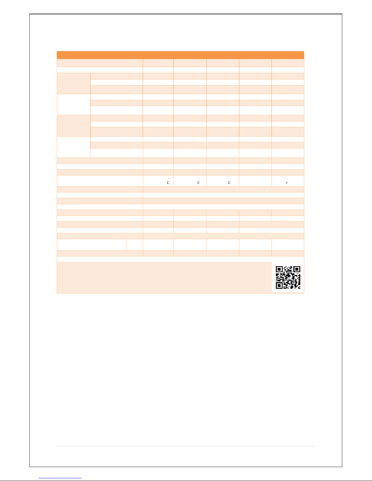
Cool Energy Pro Series Air Source Heat Pump Specification
Note: The above design and specifications are subject to change without prior notice for product
improvement. For detailed specifications of the units please refer to name plate on the units.
Correct installation is required to ensure safe operation. The requirements for Cool Energy heat
pumps include the following:
1. Appropriate site location and clearances.
2. Wiring to conform to 17
th
edition wiring regulations.
3. Adequate water flow.
This manual provides the information needed to meet these requirements. Review all application
and installation procedures completely before continuing the installation.
Cool Energy Air to Water Heat Pumps
Model
CE-H4
CE-H6
CE-H8
CE-H17
CE-iH6-18
ERP Energy Rating:
A++
A++
A++
A++
A++
Rated Capacity
@ 35°C
Water/ 20°C
Ambient
Heating Capacity
5.15kW
8.41kW
11.6kW
16.9kW
18.7kW
Power Input
1.25kW
1.9kW
2.52kW
3.6kW
3.7kW
Coefficient Performance
4.26 Cop
4.39 Cop
4.57 Cop
4.69 Cop
5.05 Cop
Rated Capacity
@ 35°C
Water/ 7°C
Ambient
Heating Capacity
4.16kW
8.16kW
10.98kW
16.5kW
17.5kW
Power Input
1.2kW
2.1kW
2.6kW
4.19kW
4.3kW
Coefficient Performance
3. 44Cop
3.88 Cop
4.2KW
3.95 Cop
4.01 Cop
Rated Capacity
@ 45°C
Water/ 20°C
Ambient
Heating Capacity
4.3kW
7.59kW
10.6kW
15.5kW
16.5kW
Power Input
1.41kW
2.1kW
2.68kW
3.8kW
3.7kW
Coefficient Performance
3.6 Cop
3.59Cop
3.95 Cop
4.06 Cop
4.46 Cop
Rated Capacity
@ 45°C
Water/ 7°C
Ambient
Heating Capacity
4.0kW
7.14kW
10.16kW
14.8kW
14.6kW
Power Input
1.21kW
2.15kW
2.68kW
4.2kW
3.9kW
Coefficient Performance
3.3 Cop
3.32 Cop
3.49 Cop
3.48 Cop
3.69 Cop
Noise:
≤52dB(A)
≤52dB(A)
≤52dB(A)
≤60dB(A)
≤60dB(A)
Rated Power Input:
1.34kW/5.86A
2kW/9.09A
2.5kW/11.4A
3.9kW/17.85A
4kW/18.8A
Max Power Input:
1.45kW/6.3A
2.2kW/10A
2.9kW/13.1A
4.6kW/20.9A
4.8kW/21.8A
Compressor Make/Model:
Mitsubishi
RN145VHEMC
Mitsubishi
RN222VHFMC
Mitsubishi
LN28VBRMC
Copeland ZW
54KWP-PFS-52E
Mitsubishi
Inverter
Power supply:
220-240V AC – 50Hz
Outlet Water Temperature:
35℃-60℃
Protection class:
IPX4
Anti-electric shock class:
Class I
Refrigerant/Charge:
R410A-800g
R410A-1000g
R410A-2000g
R410A-3000g
R410A-4100g
Average Water Flow Required:
1.75m3/H
1.9m3/H
2m3/H
3m3/H
3m3/H
Water Pump Model:
Wilo 15/6
Wilo 15/6
Wilo 25/8
Wilo PUN-200EH
Water Connections:
1” Male
1” Male
1” Male
1” Male
Climate Type:
-15~43℃
Product dimension: L x W x H:
mm
670/365/990
670/365/990
680/305/110
0
768/732/955
768/732/955
Net weight:
63kg
64Kg
68Kg
132Kg
118Kg
Manufacture Date / Serial Number See Bar Code
Cool Energy Holding Ltd
Grimsby, UK
01472 867497
www.coolenergyshop.com
 Loading...