

Page 1
Cooledge Lighting Inc.
120–13551 Commerce Parkway
Richmond, BC V6V 2L1 Canada
Cooledge Lighting reserves the r ight to change
materials or m odify the design of it s product
without notication as part of the company’s
continuing product improvement program.
5 Year Limited Warranty:
Parts and workmanship.
EN 60598 Compliant (as a system)
O +1 604 273 2665
F +1 604 273 2660
T +1 844 455 4448
W cooledgelighting.com
+ WARM -
+ COOL -
PSU
0/1 - 10V
X2
AC
DIM
CCT
X2
Caution: Observe precautions for handling electrostatic sensitive devices.
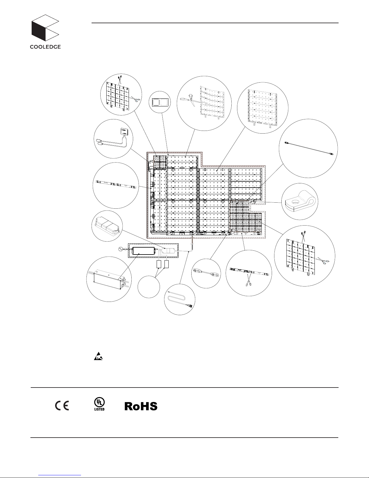
COOLEDGE TILE TUNABLE WHITE QUICK START GUIDE
For detailed instructions,
please refer to:
EX T-0043:
Cooledge TILE Tunable
White Installation
Instructions
™
EX T-00 42-R0 3-160916 1/6
Page 2
1
2
3
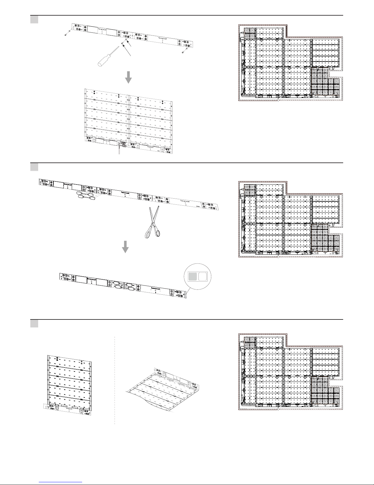
Nylon Washer
#6/M4
+ WARM -
+ COOL -
+ WARM -
+ COOL -
+ WARM -
+ COOL -
EX T-00 42-R0 3-160916 2/6
Standard Mounting 90° Mounting
Page 3
+ WARM -
+ COOL -
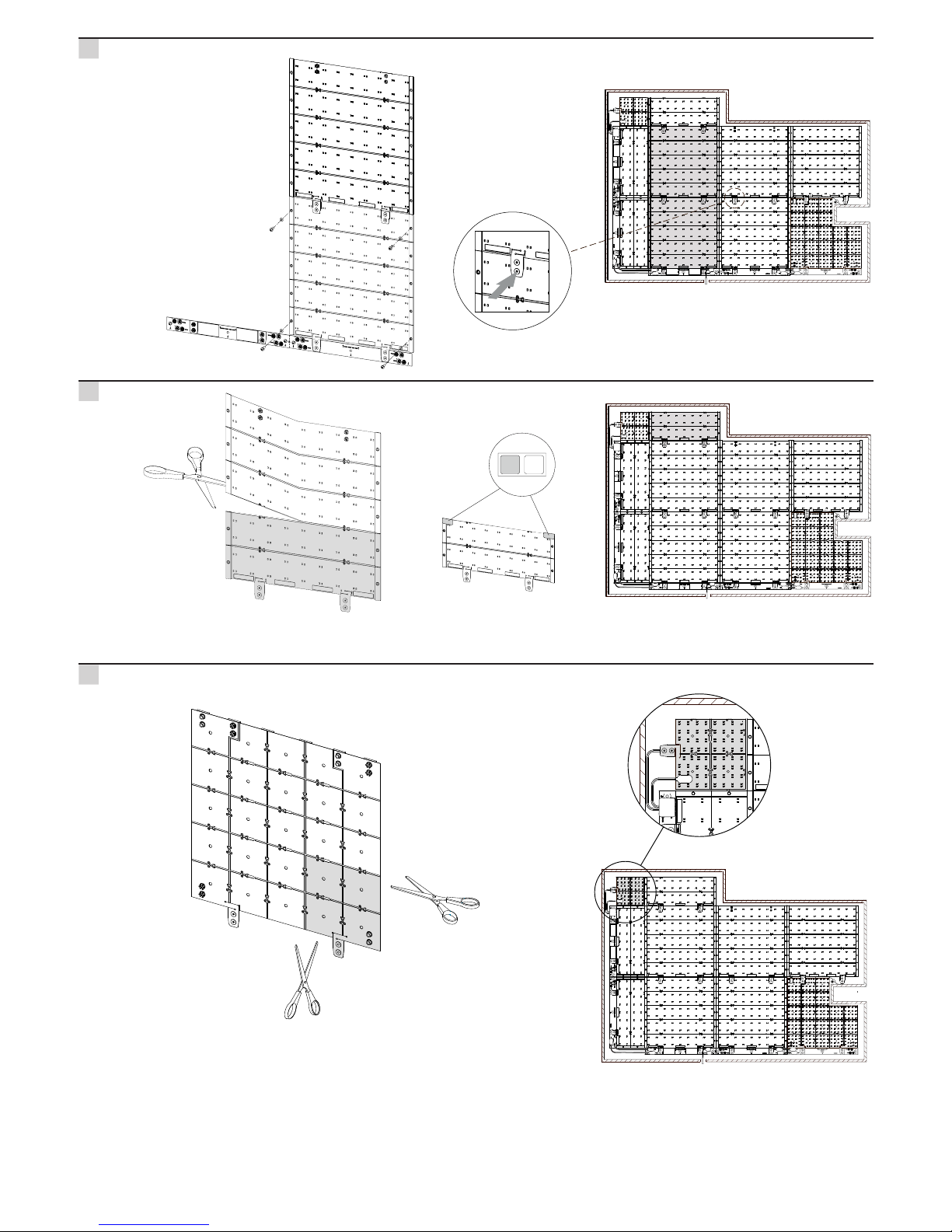
Jumper Wires
Cut Corner TILE between guide lines
+ WARM -
+ COOL -
+ WARM -
+ COOL -
Cut TILE between guide lines
+ WARM -
+ COOL -
2X
4
5
6
EX T-00 42-R0 3-160916 3/6
Page 4
+ WARM -
+ COOL -
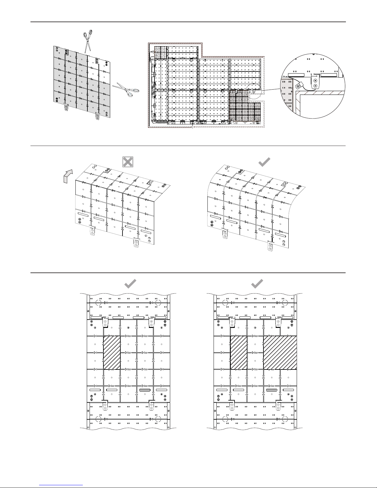
The following examples show congurations which are and are not
acceptable.
Single internal cutout. No power
connectors removed.
1. Multiple internal cutouts. No power
connectors removed.
2.
MINIMUM BEND RADIUS = 1in / 2.5cm
Jumper Wire
Cut Cutout TILE between guide lines
CUTTING TILE TUNABLE WHITE CUT-OUT
CUTTING TILE TUNABLE WHITE - DO NOT BEND SHEET SHARPLY AROUND CORNERS
TILE TUNABLE WHITE CUT-OUT - ACCEPTABLE INTERNAL CUTOUT CONFIGURATIONS
EX T-00 42-R0 3-160916 4/6
Page 5
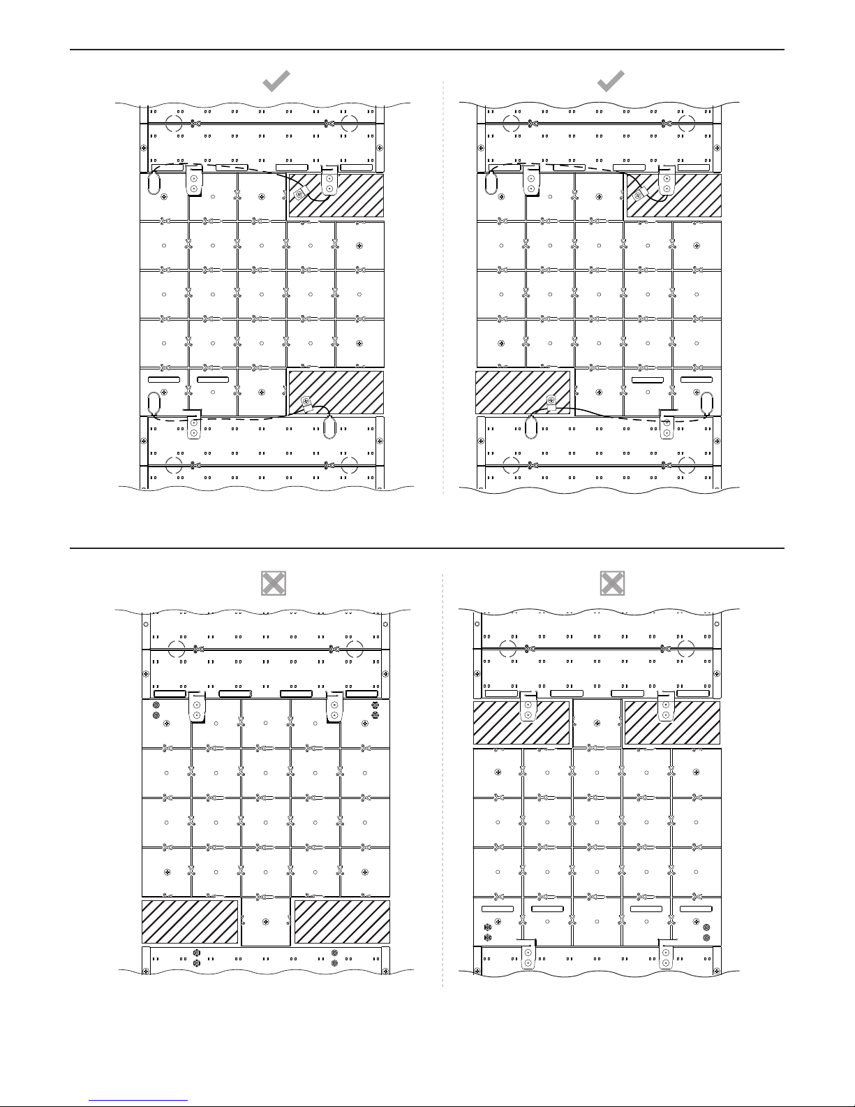
Removal of input corner and output
corner of the same polarity.
3. Removal of one input corner and one
output corner of opposite polarities.
4.
Removal of both input corners.5. Removal of both output corners.
Cutout TILE in the middle of the run.
6.
TILE TUNABLE WHITE CUT-OUT - ACCEPTABLE CORNER CUTOUT CONFIGURATIONS
TILE TUNABLE WHITE CUT-OUT - UNACCEPTABLE CORNER CUTOUT CONFIGURATIONS
EX T-00 42-R0 3-160916 5/6
Page 6
CE CompliantUL Listed
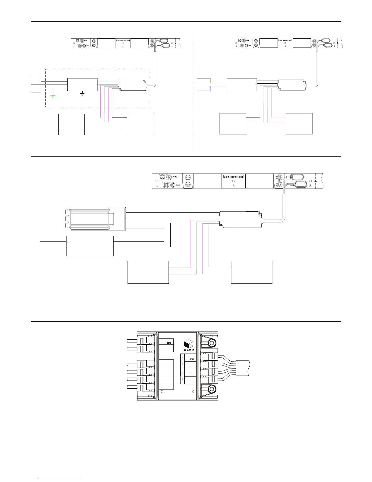
DRIVER
Black
Line
Neutral
Earth
White
Red
Blue
Green/Yellow
Electrical Enclosure
Violet (+)
Grey (-)
0/1 - 10V
Dimming Channel
Violet (+)
Grey (-)
0-1 - 10V
Tuning Channel
Violet Dimmer (+)
Grey Dimmer (-)
Violet CCT (+)
Grey CCT (-)
TW LED Control Unit
Connector Strip
To TILEs
Starter
Cable
DRIVER
Brown
Line
Neutral
Blue
Violet (+)
Grey (-)
0/1 - 10V
Dimming Channel
Violet (+)
Grey (-)
0/1 - 10V
Tuning Channel
Violet Dimmer (+)
Grey Dimmer (-)
Violet CCT (+)
Grey CCT (-)
TW LED Control Unit
Connector Strip
To TILEs
Starter
Cable
VIN
58V
DIM (-)
DIM (+)
VIN
0V
CCT (+)
CCT (-)
RED (+)
58V
BLACK (-)
WHITE (+)
58V
GREEN (-)
WIRED TWC LED Control Unit
CH
1
CH
2
Line
Neutral
Violet (+)
Grey (-)
0/1 - 10V
Dimming Channel
Violet (+)
Grey (-)
0/1 - 10V
Tuning Channel
Violet Dimmer (+)
Grey Dimmer (-)
Violet CCT (+)
Grey CCT (-)
TW LED Control Unit
Connector Strip
To TILEs
Starter
Cable
Green: Power Out (-)
White: Power Out (+)
Orange: Power In (+)
Grey: Power In (-)
Red: Power In (+)
Black: Power In (-)
AC to DC
3rd Party Driver
24 - 48V Output
Voltage Booster (VB90)
3rd Party Driver
WIRING
EX T-00 42-R0 3-160916 6/6
 Loading...