

Page 1
Advanced Ventilation Controller (TC-AVC) Installation Instructions
WARNING - THIS IS A HIGH VOLTAGE PRODUCT ONLY (110/220V AC)
- DO NOT CONNECT TO LOW VOLTAGE DEVICES - ALL RELAYS OUTPUT 110/220V AC
- CONNECTING LOW VOLTAGE DEVICES/RELAYS WILL DAMAGE THE EQUIPMENT
GENERAL OVERVIEW:
This is an overview to fundamentally understand this product. It
cannot be stressed enough that this is purely a high voltage AC
controller; there are no low voltage contacts. Do Not Connect
Low Voltage Relays or Contact Closures. Another important
note is that while there are Low, Medium, High indicators, this is
Not a Speed Controller - no matter the relays used, the fan will
operate at a single speed. The intention is that additional fans
can be used to increase airflow or a separate speed controller
may be available in the future that utilizes the additional relays.
The unit functions using 5 relays: three of the relays are
assigned to different fan modes and 2 are associated to alarm
functions. Each relay’s output is identical (110/220V AC) so how
the relays are configured can vary which is discussed later in the
‘Advanced Applications’ section. The alarm relays work in
conjunction with a separate user defined set point and are for
use with high voltage devices only (audible alarms, strobes).
The functionality of each relay is as follows: Relay 1 ‘triggers’ in
relation to the primary user defined setpoint. Relay 2 triggers
approximately 6
triggers approximately 15
4/Alarm 1, is triggered in relation to the alarm setpoint (also user
defined), and Relay 5/Alarm 2, is triggered 10
setpoint.
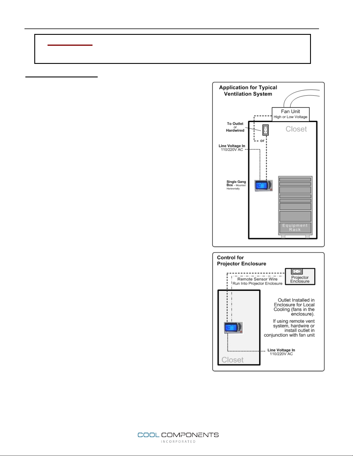
Standard Application: For normal use and the most common
application, a high or low voltage fan will be connected to the
primary (#1) relay and other relays will not be used. Low voltage
fans are connected by installing an outlet that is fed through and
automated by the controller.
Advanced Applications: The relays can be used to trigger
different banks of fans. One scenario is that one set of fans can
be connected to relay 1 and trigger at the primary setpoint.
Additional fans can be connected to relays 2 and 3 to turn on as
the system temperature increases and the additional points are
reached in the controller (the settings for relays 2, 3, & 5 (Alarm
2), cannot be changed; they are relative to the user defined
setpoints. This configuration will provide additional cooling as
the system temperature increases and can be used to aid
efficiency by only running fans when necessary.
The alarm relays can be used for separate high voltage alarms
or for additional fan units. This will provide a second user defined setpoint and the potential for 5 banks of
fans and/or different degrees of alarms.
With being high voltage relays, one or more relays can be used for any purpose as long it corresponds to a
high voltage device or connection. It is limiting to only consider them appropriate for Fans and Alarms but it
cannot be stressed enough that they cannot be used for contact closures or any device that is not rated for
the specified voltage – either 110/220V AC.
o
F above the primary setpoint, and Relay 3
o
above the primary setpoint. Relay
o
F above the alarm
Page 2
BUTTONS
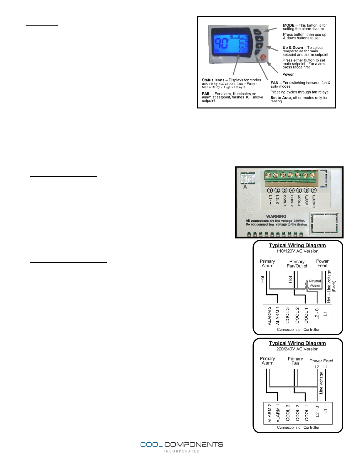
MODE – The mode button is used for programming the
alarm feature.
FAN – The fan button is used to determine Auto versus
Manual Modes. Manual modes are for testing the unit as
the unit should always be in Auto mode for normal
operation. When pressing the fan button, the unit moves
between the different relays and cycles to Auto mode.
The corresponding icons will illuminate and trigger the
appropriate relays
Low = Relay 1
Med = Relay 2
High = Relay 3
(detailed below).
Auto = Normal operating mode
Fail = Alarm 1
Fail
(Flashing) = Alarm 2
When cycling through the Fan modes, all relays will turn on (High, Med, Low) which indicates that all
relays are activated. When pressed again, the relays will be turned on and off. Note: The ‘Low’ relay
may not go off if the unit’s setpoint is lower than the ambient temperature.
LOCATING THE UNIT
Ensure to locate this controller where it will not be confused with
HVAC thermostats. The ideal location will be inside electronic closets
or of course the rack versions will be mounted on the front or back of
the rack. If using the built-in temperature sensor, ensure it is in a
position where AC or Heat is not being blown onto the unit and avoid
sunlight and areas in general where temperature may not be
accurate.
For wall/closet applications, the unit should be installed in a single
gang electrical box turned sideways.
CONNECTING THE UNIT
Note: This unit should only be connected by a qualified and licensed
electrician. This is a high voltage device; mis-wiring will cause
serious injury and/or damage the unit. Check and follow all local and
applicable building codes.
Wiring Incoming Power: 110/120V: Connect the Line Voltage to L1 & L2
– typically black (hot) wire to L1 and white (neutral) wire to L2-0. The unit
does not require a ground. 220/240V: Connect power feeds to L1 & L2.
Wiring Fan: 110/120V: If only one fan is being powered, connect the hot
lead to COOL 1 (location 3) and connect the neutral to L2. You will have to
connect all neutral wires together and then supply a single lead to L2.
If connecting more than one fan that will be triggered separately, connect
the hot wire for each fan to the corresponding and desired relays. Cool 2 =
Relay 2 = The second point where a fan will turn on (approx 6
setpoint). Cool 3 = Relay 3 = the 3
rd
point where the fan will turn on/off
(approx 15oF above the primary setpoint).
Alarm Wiring: High Voltage Alarms can be wired to the unit but ONLY
HIGH VOLTAGE, DO NOT CONNECT TO LOW VOLTAGE CONTACT
CLOSURES OR OTHER DEVICES!!! This may include alarms, buzzers,
strobes, etc.
o
F above the
Page 3
Connect the primary alarm to Alarm 1 and the secondary or critical alarm that will be activated approx
o
F above the Alarm setpoint, to ALARM 2. Again, all neutral wires will be connected together and run
10
to L2.
Notes: A high voltage relay can also be used to then trigger a low voltage device (must be purchased
and configured separately). Support is not available for such configurations.
External Sensor: An optional external sensor is available and plugs into the connector in the upper left
corner on the back of the unit, designated on the controller as ‘A’. If the external sensor is not
connected, the internal sensor is utilized by default. Connect the sensor prior to powering up the unit
and the unit will automatically recognize it. If wanting to add the sensor after powering the unit, simply
remove power, add sensor, and re-power the unit. The sensor can be extended if necessary by using
22ga, 2 conductor wire (22/2) but follow typical low voltage wiring practices. Typically the external
sensor would only be used for remote installations such as projector enclosures or where the
temperature monitoring and controlling is separate from where the controller is positioned.
CONFIGURING & PROGRAMMING THE UNIT
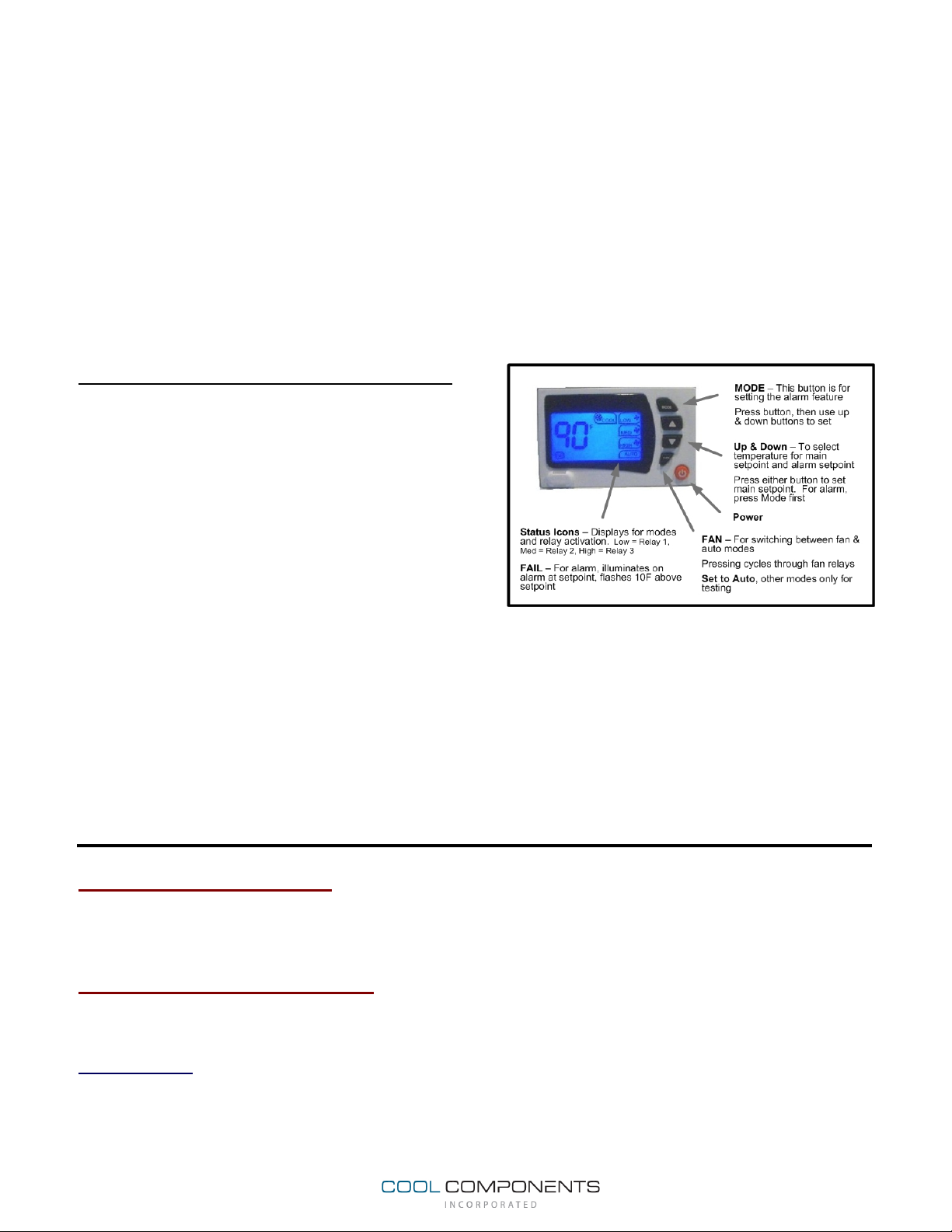
Primary Setpoint: The primary setpoint is
programmed by simply pressing the up or down
buttons. Simply press one of the buttons and the unit
will enter programming mode represented by the
flashing display. Select the desired setpoint and the
unit will automatically exit programming mode after 3
seconds. Once set, the first relay will turn on when
that setpoint is reached. The fan will then turn off at
o
2
F below the setpoint which prevents the unit from
frequently cycling on and off.
Alarm Programming: The alarm setpoint is determined by simply pressing the Mode button. When
pressed, the unit goes into programming mode. Simply select the alarm setting by pressing the Up or
Down buttons. The unit will exit programming mode after 5 seconds if no buttons are pressed.
At this point the unit is programmed and ready for use.
Note: If using additional fans, Fan 2 & 3 are turned on at set points relative to the primary setpoint and
cannot be adjusted independently. If a critical alarm is being connected utilizing Alarm 2, that is also a
point relative to the alarm setpoint as described above.
Display: To change between Celsius and Fahrenheit, simply press and hold the power button for
approximately 10 seconds.
Unit Not Working?
Do not Return Damaged or Defective Products to Point of Purchase. If the unit arrived non-functional or
damaged, we will resolve the issue quickly and hassle-free. Contact us on the web at
www.coolcomponents.com/warranty
Warranty Information
This unit is guaranteed to be free of defects for a period of one year from the date of purchase. This warranty
excludes damage caused by misuse or for applications other than the intended use of the products.
Feedback
We truly value feedback on this and all of our products. We strive to provide the best products possible so it is
important that we learn from our customers. If you have any ideas or suggestions that could improve this or
any of our other products, please let us know. Thank you in advance for sharing your experience. Please send
feedback to
 Loading...