

Page 1

Coolcentric, A Division of Vette Corp
201 Boston Post Road West, Marlborough, MA 01753
Email [email protected] Website www.coolcentric.com
INSTALLATION GUIDE
Issue 1.0
CDU-AC5 Web Server/MODBUS
Gateway
Page 2

Web Server Installation Guide Page 2
CDU-AC5
CONTENTS
Section 1 INTRODUCTION
1.1 General 3
Section 2 SYSTEM OVERVIEW
2.1 Features and Capabilities 4
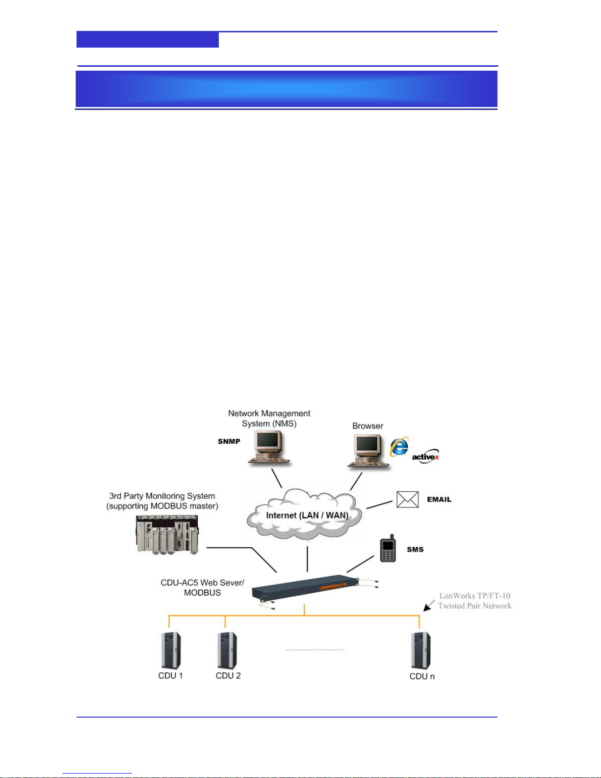
2.2 Architecture 4
Section 3 TECHNICAL DATA
3.1 Mounting 5
3,1,1 Cabinet Mounting 5
3.1.2 CDU Mounting 5
3.2 Wiring Connections 6
3.3 LEC Indicators and Buttons 7
Section 4 INSTALLATION
4.1 Power Supply 8
4.2 Access the CDU-AC5 9
4.3 Installing the ActiveX control 9
Section 5 CONFIGURATION
5.1 General 10
5.2 Configuring the CDU’s Network Address 10
5.3 Attaching the CDU to the CDU-AC5 10
5.4 CDU-AC5 12
5.4.1 General Tab 12
5.4.2 Users Tab 14
5.4.3 Alarms Tab 15
5.4.4 Plots Tab 16
5.4.5 S Days,Ip Out and Trend Tabs 16
5.5 Personalising the Site Map Schematic 17
Section 6 OPERATION
6.1 Logging On 20
6.2 Navigating Schematics 21
6.3 CDU Schematics 22
6.3.1 Overview 22
6.3.2 Alarms 23
6.3.3 Historic 23
6.3.4 Input/Output Status 24
6.3.5 Parameters 25
6.4 Displaying Alarms 26
Page 3

Web Server Installation Guide Page 3
CDU-AC5
1.1 General
This guide describes the basic Installation, Configuration and Operation of the CDU-AC5 Web
Server and MODBUS gateway. The CDU-AC5 is a multi-function communication gateway that
provides a means to monitor and control CDU cabinets via a number of standard Internet and
Building Automation protocols.
INTRODUCTION
Section 1
Page 4
Web Server Installation Guide Page 4
CDU-AC5
2.1 Features and Capabilities
Graphic Hosting. Hosting of schematics which can real-time data fields retrieved from
the locally connected CDUs via the LonWorks network. Adjustment of set points and
other configuration property values is provided with relevant security schemes.
Schematics can be viewed from Windows Internet Explorer, and achieved with the
support of a signed ActiveX control.
Alarming & Re-transmission. Generation and storage of alarms from local CDUs. Re-
transmission via E-mail or SMS (requires GSM Modem).
Data Logging. High capacity logging to miniSD card. Multiple sources and log intervals
are supported.
SNMP. SNMP agent support, providing a monitoring solution to existing network
management systems.
MODBUS. MODBUS slave support via a RS-485 serial communication link, providing a
monitoring solution to any Building Management System (BMS) that supports MODBUS
RTU protocol.
2.2 Architecture
SYSTEM OVERVIEW
Section 2
Page 5

Web Server Installation Guide Page 5
CDU-AC5
3.1 Mounting
The CDU-AC5 is supplied with two sets of end brackets which allow mounting in either a
standard 19” cabinet or a CDU cabinet.
3.1.1 Cabinet Mounting
3.1.2 CDU Mounting
TECHNICAL DATA
Section 3
Alternative end brackets
suitable for 1-screw vertical
mounting to CDU frame
member– bottom bracket
locates with tabs in frame
upright slots.
End brackets suitable for 4-screw
horizontal mounting in standard
19” cabinet.
Page 6
Web Server Installation Guide Page 6
CDU-AC5
3.2 Wiring Connections
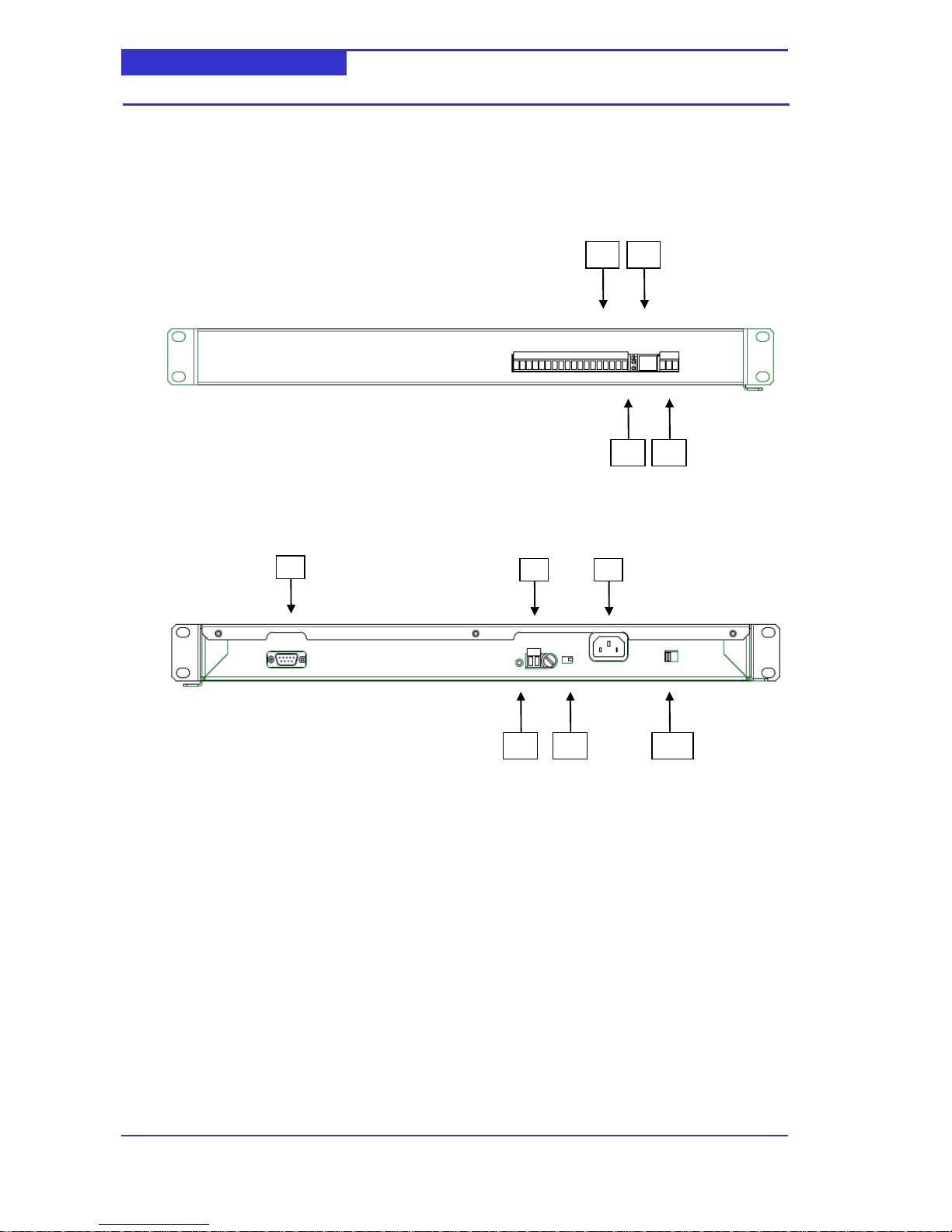
The CDU-AC5 is provided with a series of two part screw wiring terminals and a RJ-45 data
connection. In addition, there is a DB-9 communication port for connection to a GSM modem
and several other connections which are not utilised.
Front View
Rear View
1 CDU LonWorks Data Port.
The LonWorks data port provides connection to the local CDUs via a polarity
independent twisted pair.
2 RJ-45 10/100 BaseT Ethernet Port.
The RJ-45 connector must be used with a RJ-45 male connector and a suitable
Category 5 or Category 6 data cable connected to a 10BaseT or 100BaseT channel.
On power-up, the CDU-AC5 will automatically adjust to the speed of the data port.
4 RS-485 MODBUS Port.
Two part screw terminal, for connection to MODBUS master device. +,- and GND
signals available.
5 DB-9 RS232 Serial Port.
Standard serial port for connection to optional GSM modem.
6 24Vac power supply terminal
Two part screw terminal for connection to 24Vac power supply.
8 9 10 3 4 1 2
7 5 6
Page 7

Web Server Installation Guide Page 7
CDU-AC5
7 Mains power supply terminal
IEC socket for connection to mains power supply.
3.3 LED Indicators, Switches and Buttons
3 Unit Status LED (Green).
Indicates status of unit. Flashing 1 second interval indicates healthy condition.
8 LonWorks Service Button
Used to generate `Servie pin message’. This is used during the configuration of
CDUs.
9 24V/Mains Selector Switch
Used to select between external 24Vac and mains power supplies.
10 230V/115V Selector Switch
Used to select between 115V or 230V mains power supplies.
Page 8
Web Server Installation Guide Page 8
CDU-AC5
4.1 Power Supply
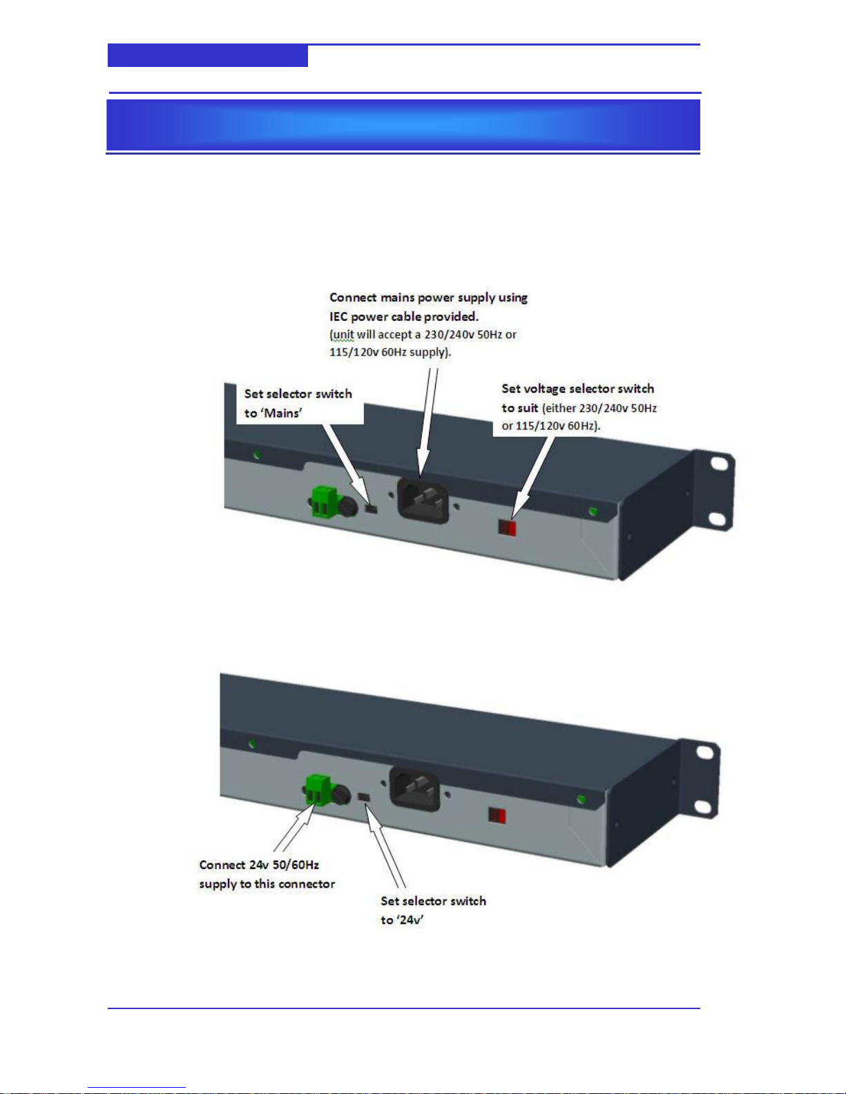
The CDU-AC5 can be powered by either a local 24Vac or mains supply. Typically, you will
use 24Vac if the CDU-AC5 is mounted in a CDU and mains if it is rack-mounted.
Mains Power Supply Option
24Vac Power Supply Option
NOTE: The CDU-AC5’s 24Vac power supply is polarity sensitive – it is
extremely important to get the 24v & 0v in the correct orientation to avoid
damage to the CDU-AC5
INSTALLATION
Section 4
Page 9
Web Server Installation Guide Page 9
CDU-AC5
4.2 Local LonWorks Network
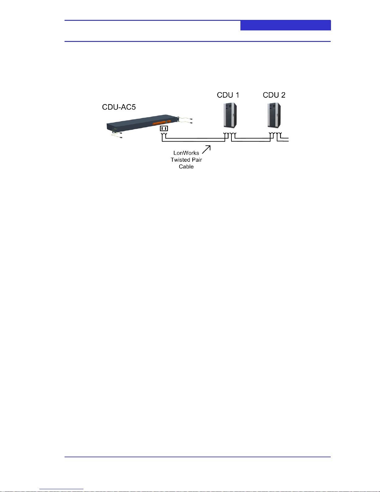
The CDU-AC5 communicates with connected CDUs over a LonWorks twisted pair network. A
typical network is shown in below,
4.3 Accessing the CDU-AC5
The CDU-AC5 can be accessed from a client PC running Microsoft Internet Explorer 5 or
above. The following security options must be enabled within Internet Explorer,
Scripting
Active X Controls
The CDU-AC5 communicates using a number of standard and non-standard TCP ports. If
access is to be gained through a firewall, the following ports are should be open.
20-21
80
44000 – 44002
50000 – 50010
The default IP configuration of the web server is
IP Address 192.168.11.22
Subnet Mask 255.255.255.0
Default gateway 0.0.0.0
4.4 Installing the Active-X control
When accessing a CDU-AC5 for the first time, an Active-X control will be downloaded and
installed on the client PC. The download is an automated process - the user only needs to
confirm several security prompts.
Page 10
Web Server Installation Guide Page 10
CDU-AC5
5.1 General
A CDU-AC5 can monitor and control a number of CDUs. The number of CDUs which can be
connected to the CDU-AC5 is dependent on the CDU-AC5 firmware. As of writing the
following firmware images are available,
CDU-AC5 Firmware Version
Maximum number of CDUs
3CDU 1.0.0 onwards
3
8CDU 1.0.0 onwards
8
A CDU must be connected to the CDU-AC5 gateway using the procedure documented in this
section.
5.2 Configuring the CDU’s Network Address
Before a CDU can be attached to the CDU-AC5 gateway it must be given a unique network
address. Typically, network addresses are allocated to CDUs in ascending order, starting
from 1. Configuration of the CDU network address is carried out via the CDU’s graphical
display.
i. Logon at Service Level or above.
ii. Navigate to `Connectivity->N/W Address’ (screen level 8-1)
iii. Press OK
iv. Enter the required network address
v. Press OK
5.3 Attaching the CDU to the CDU-AC5
i. Logon at Service Level or above.
ii. Navigate to Connectivity->Web Server->Attach (screen level 8-2-1)
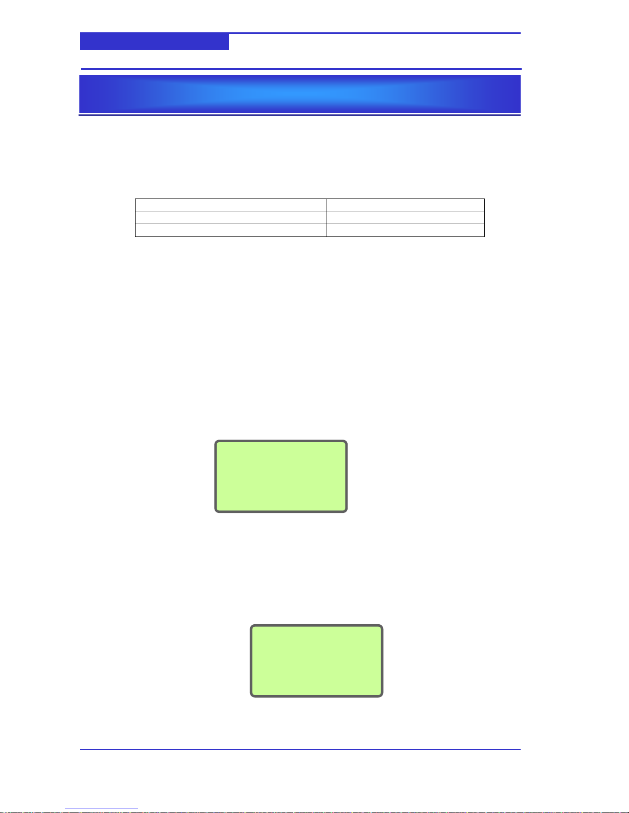
iii. Press OK. The screen shown below will be displayed.
iv. Press the Service button of the CDU-AC5.
v. The screen will report the status of the attachment process. A series of screen
updates will be displayed.
CONFIGURATION
Section 5
N/W Address
Use Arrow keys
01
Attach
Press serv. pin
Page 11

Web Server Installation Guide Page 11
CDU-AC5
vi. When the process is completed the following screen will be displayed.
vii. Press OK
Attach
Updating domain
x of y
Attach
Setup complete
Press OK
Attach
Updating address
x of y
Attach
Updating nv
x of y
Page 12
Web Server Installation Guide Page 12
CDU-AC5
5.4 CDU-AC5
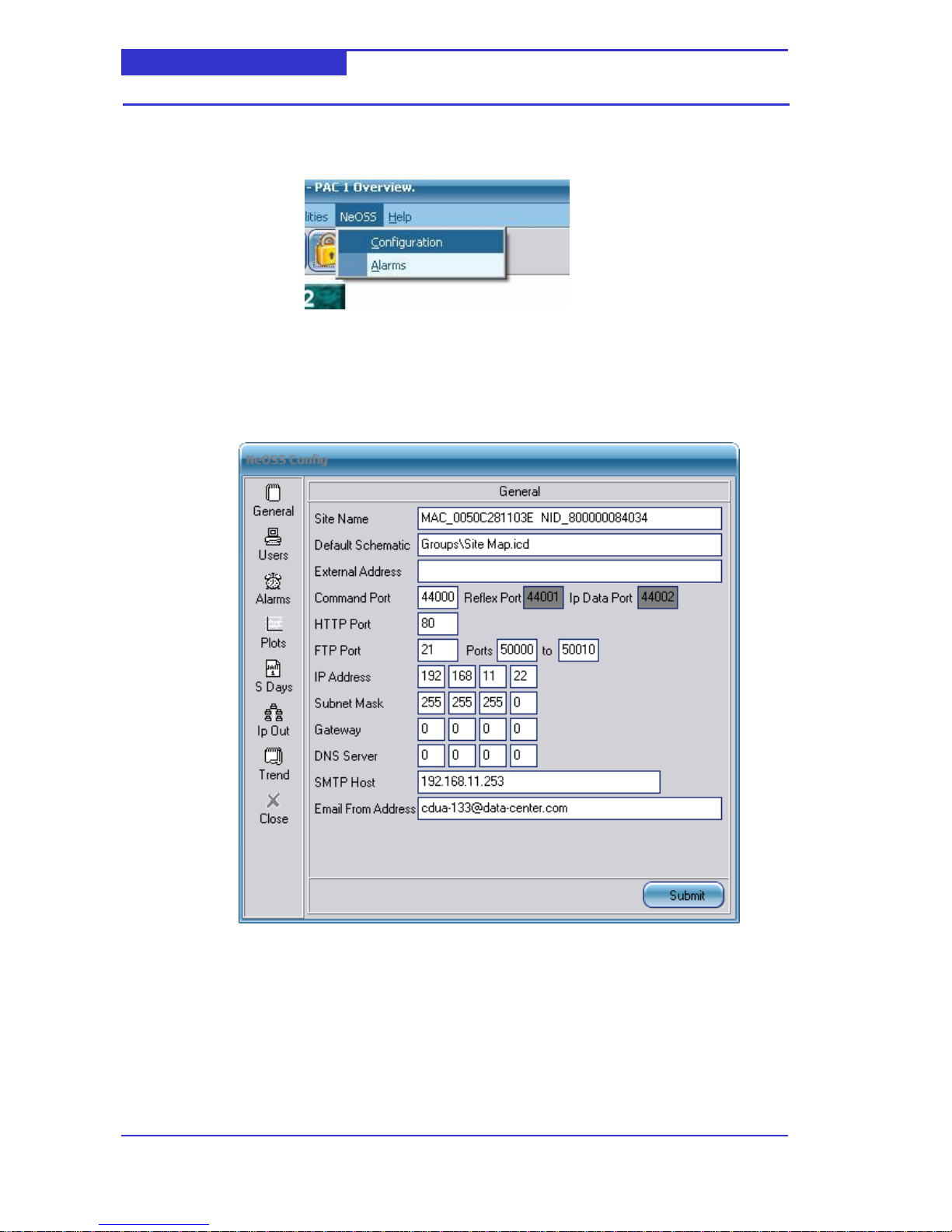
To access the configuration of the CDU-AC5 select Configuration from the NeOSS menu.
You will be asked to Logon. Enter the username and password.
5.4.1 General
The General screen allows you to configure the basic parameters of the CDU-AC5.
Site Name
Provides a space to enter the site name of the CDU-AC5. The site name is used to
cache schematics on the hard disk of the client PC.
Default Schematic
Provides a space to enter the default schematic which is displayed when a user
connects to the CDU-AC5 without providing a valid username or password.
External Address
Not used in current release
Page 13

Web Server Installation Guide Page 13
CDU-AC5
Command Port/Reflex Port/IP Data Port (Default =
44000/44001/44002)
These ports used by the web-client (Internet Explorer etc) and the CDU-AC5.
HTTP Port (Default = 80)
Provides a space to enter the port number to be used by http. Normally this is set to
the standard value of 80, and would only be changed if multiple web servers are
present.
FTP Port (Default = 21)
Provides a space to enter the port number to be used by ftp. Normally this is set to
the standard value of 21, and would only be changed if multiple CDU-AC5 or ftp
servers are present.
Passive FTP Ports (Default = 50000 to 50010)
Provides a space to enter the range of port numbers to be used by ftp.
IP Address
Provides a space to enter the Internet Protocol (IP) static address of the CDU-AC5.
This address will be supplied by your network administrator.
NOTE: DHCP is not supported.
Subnet Mask
Provides a space to enter the subnet mask number obtained from your network
administrator. This number is combined with the IP Address number to identify which
network segment the CDU-AC5 is on.
Gateway
Provides a space to enter the address of the default gateway. This is the address of a
local IP router which is used to forward traffic to destinations beyond the local
network.
DNS Server
Provides a space to enter the address of the DNS Server. This server is used to
resolve DNS names to IP Addresses of DNS names queried by the CDU-AC5 that
can not be resolved using local name resolution information.
SMTP Host
Provides a space to enter the name of the SMTP host. This is the name of email
server that the CDU-AC5 uses to send email messages to. This field is required if
alarms or datalogs are to be sent via email.
Email from Address
Provides a space to enter the address that should appear in the `from’ field of emails
generated by the CDU-AC5. This field is required if alarms or datalogs are to be sent
via email.
Modifying Configuration
1. Modify the required values
2. Click Submit. The following message box will be displayed,
3. Click OK
4. Click Close
5. If you changed the IP settings (IP Address, Subnet Mask, Gateway) the
following message box will be displayed.
Page 14

Web Server Installation Guide Page 14
CDU-AC5
6. Click OK. The CDU-AC5 will perform a reboot. Once complete, you may log on
again.
5.4.2 Users
The Users screen allows you to manage the user database.
Adding a User
2. Click on the New User icon, .
3. Enter the required Login Name, User Name and Password.
4. The Access Level should be set accordingly,
< 90 if adjustments to CDU parameters are not to be permitted from the schematics.
>= 90 if adjustments to CDU parameters are required
5. Select Engineer if access to the configuration options is required
6. Select Administrator if access to the Users is required.
7. Single left click on the Default Schematic entry field. A window will be displayed
which allows you to select the default schematic. The default schematic is the schematic
which is initially displayed when the user logs on.
Page 15
Web Server Installation Guide Page 15
CDU-AC5
8. Click Submit
Deleting a User
1. Highlight the User to delete in the current User Name list.
2. Click on the Delete User icon, .
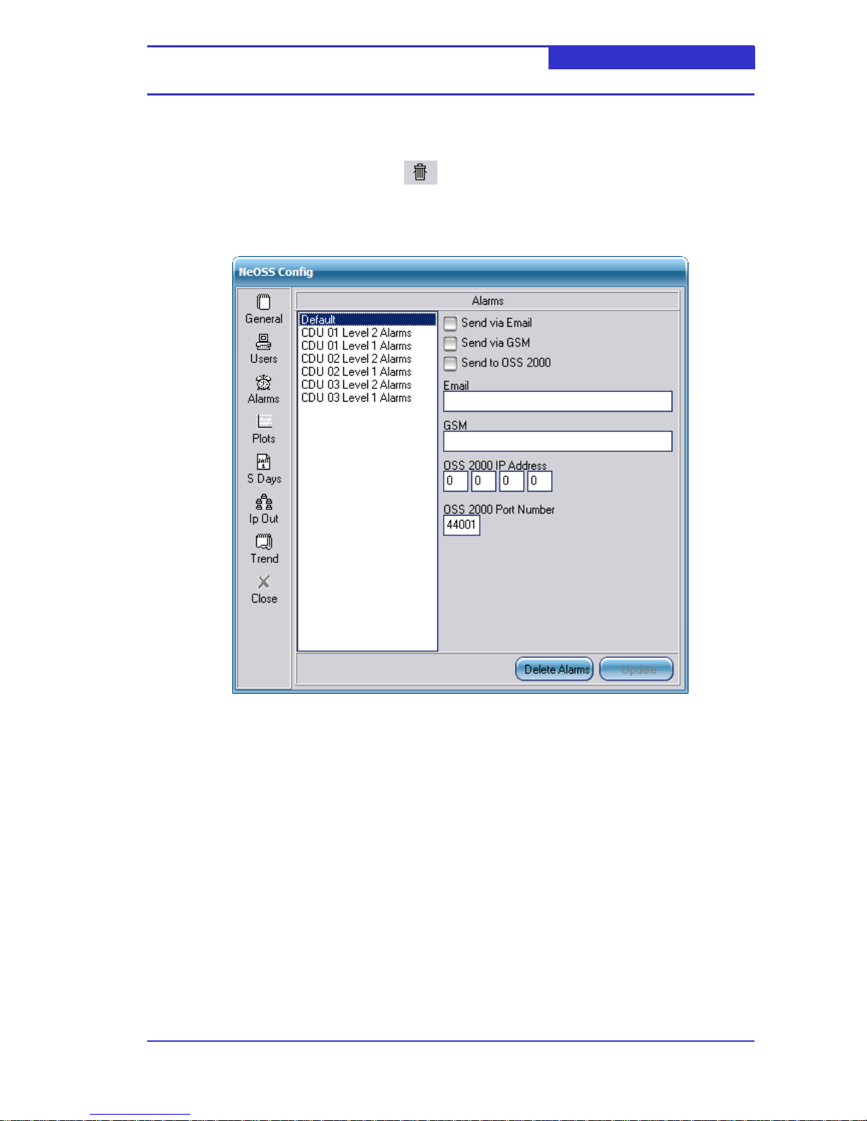
5.4.3 Alarms
The alarms screen allows you to configure re-transmission options for alarm groups. The
`Delete Alarms’ button is used to delete the archived alarm list.
Page 16
Web Server Installation Guide Page 16
CDU-AC5
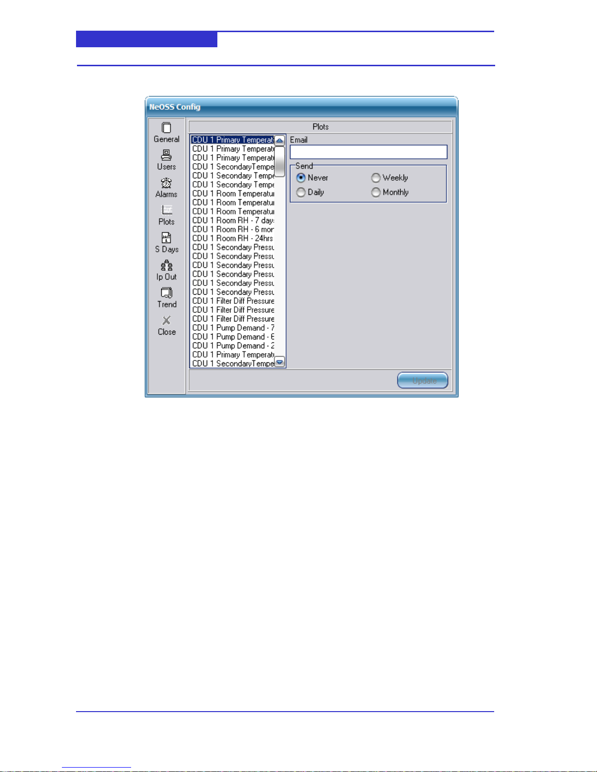
5.4.4 Plots
The plots screen allows you to configure when plots (datalogs) are emailed out.
5.4.5 S Days,Ip Out and Trend.
These screens are not utilised in this release.
Page 17

Web Server Installation Guide Page 17
CDU-AC5
5.5 Personalising the Site Map Schematic
The site map is normally the default schematic which is displayed when a user logs on to the
CDU-AC5 and presents the CDUs which are attached to the CDU-AC5.
A newly installed CDU-AC5 will not be attached to any CDUs –this is represented by the
following site map schematic.
Once you have attached a CDU to the CDU-AC5 (see section 5.1 and 5.2), a CDU icon will be
displayed on the site map. In the schematic shown below, a CDU with network address #1
has been attached.
Attaching a CDU with Network address #2, #3 etc will be represented by CDU icons
positioned to the left of CDU #1.
Page 18
Web Server Installation Guide Page 18
CDU-AC5
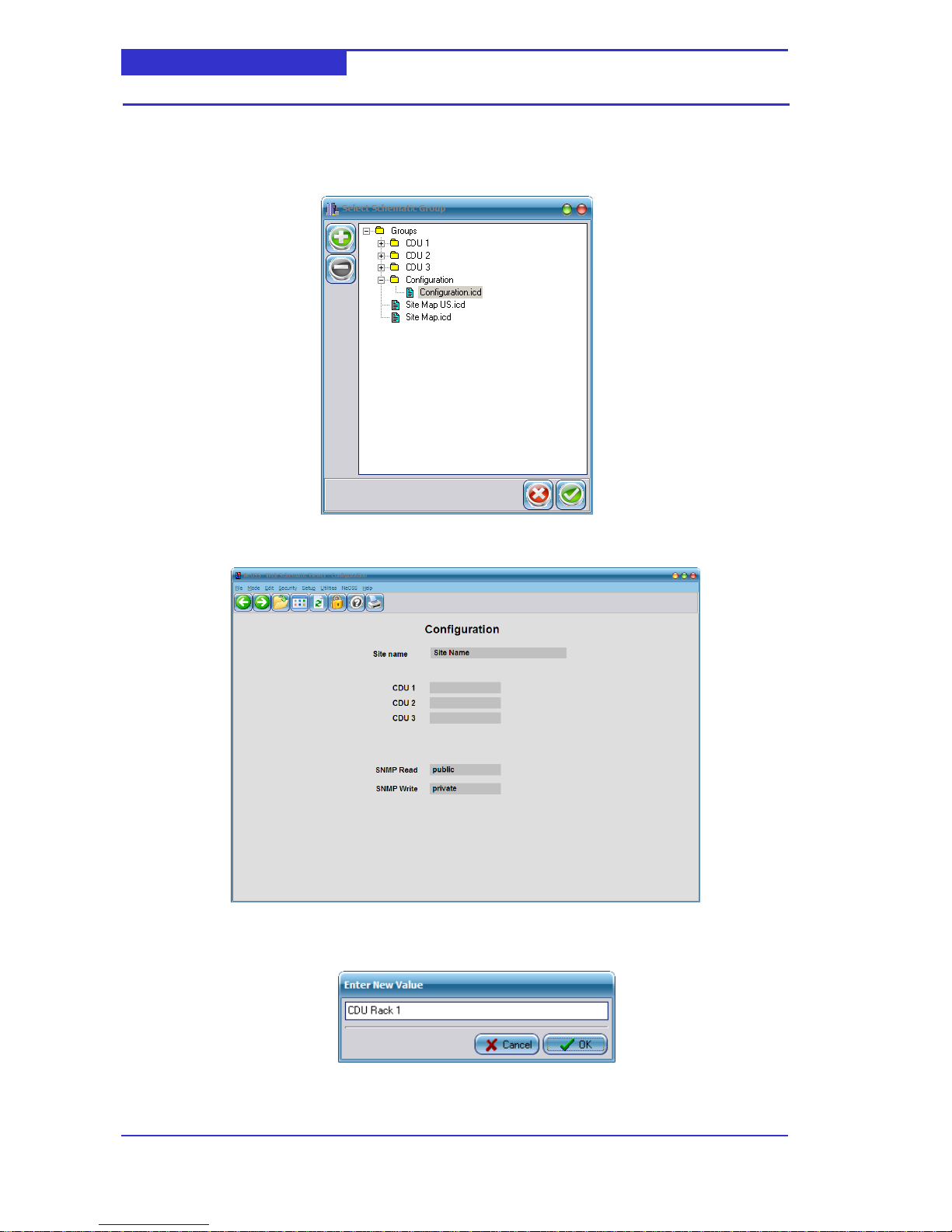
Naming the Site Map
1. From the Menu, select File -> Open ->In Main Window.
2. Select the Configuration schematic as shown below,
3. The following schematic will be displayed.
4. Click on the Site Name entry field to display the Enter New Value dialog.
5. Enter the required and click OK
Page 19
Web Server Installation Guide Page 19
CDU-AC5
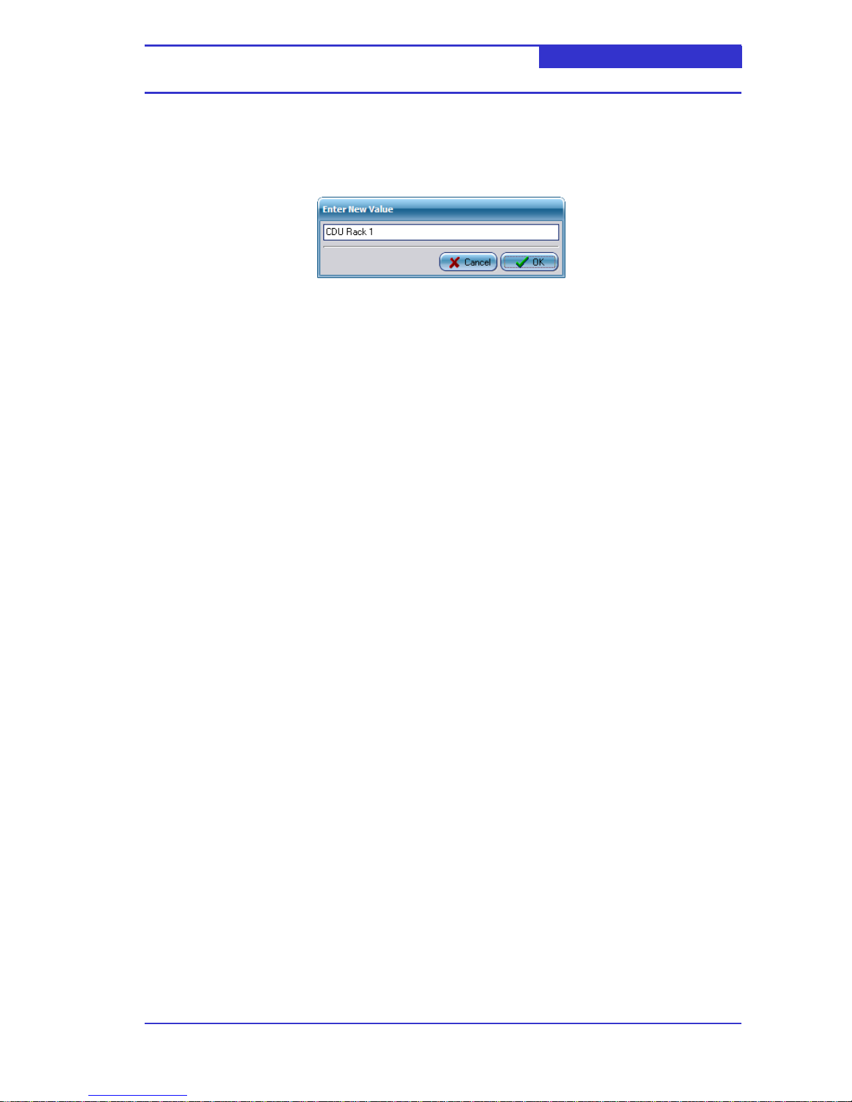
Naming a CDU
1. Open the Configuration schematic as described in `Naming Site Map’
2. Click on the appropriate CDU x entry field to display the Enter New Value
dialog.
3. Enter the required and click OK.
Page 20
Web Server Installation Guide Page 20
CDU-AC5
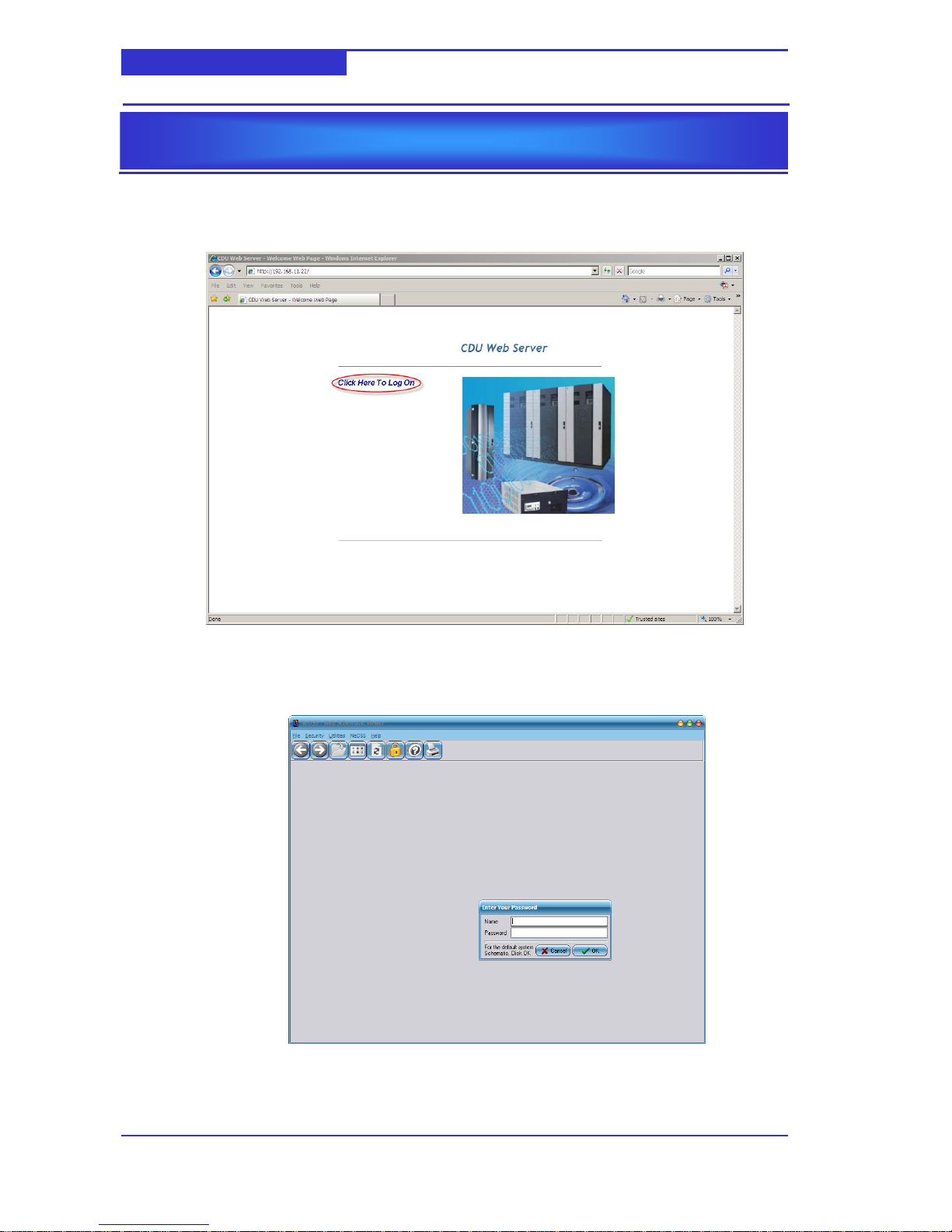
6.1 Logging On
From the web page, click `Click here to Log On’.
The schematic viewer ActiveX control will be launched and a logon dialog box will be
displayed – enter the appropriate username and password.
OPERATION
Section 6
Page 21
Web Server Installation Guide Page 21
CDU-AC5
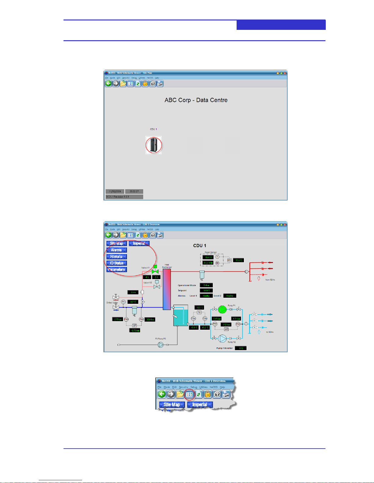
6.2 Navigating Schematics
The site map is the default schematic displayed when the user logs on. To navigate to the CDU click
the appropriate CDU picture.
The user may easily navigate between schematics by clicking on the blue marble buttons.
To return to the default schematic click the Default schematic button as shown below,
Page 22
Web Server Installation Guide Page 22
CDU-AC5
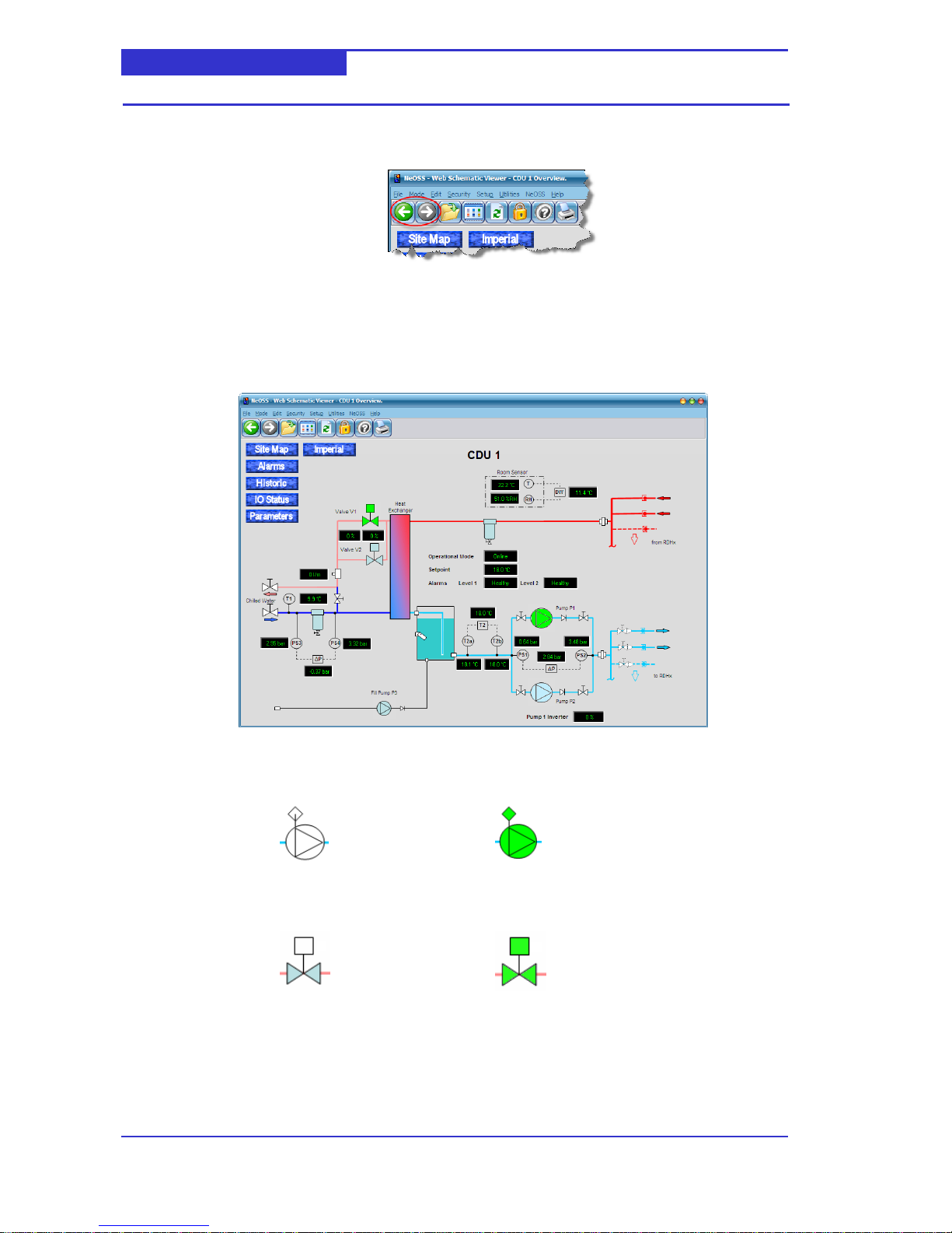
In addition, the user may step backwards or forwards through the schematics they have
previously viewed by clicking the buttons shown below,
6.3 CDU Schematics
6.3.1 Overview
The overview schematic provides an at-a-glance status of the CDU. It is presented as a piping
backdrop onto which are positioned a number real-time data points. These data points are
either numerical values or state bitmaps.
For the secondary pumps and fill pump, the following bitmaps are used to indicate their state,
For the heat exchanger valves the following bitmaps are used to indicate their state,
Pump OFF
Pump ON
Valve Closed
Valve Open
Page 23
Web Server Installation Guide Page 23
CDU-AC5
6.3.2 Alarms
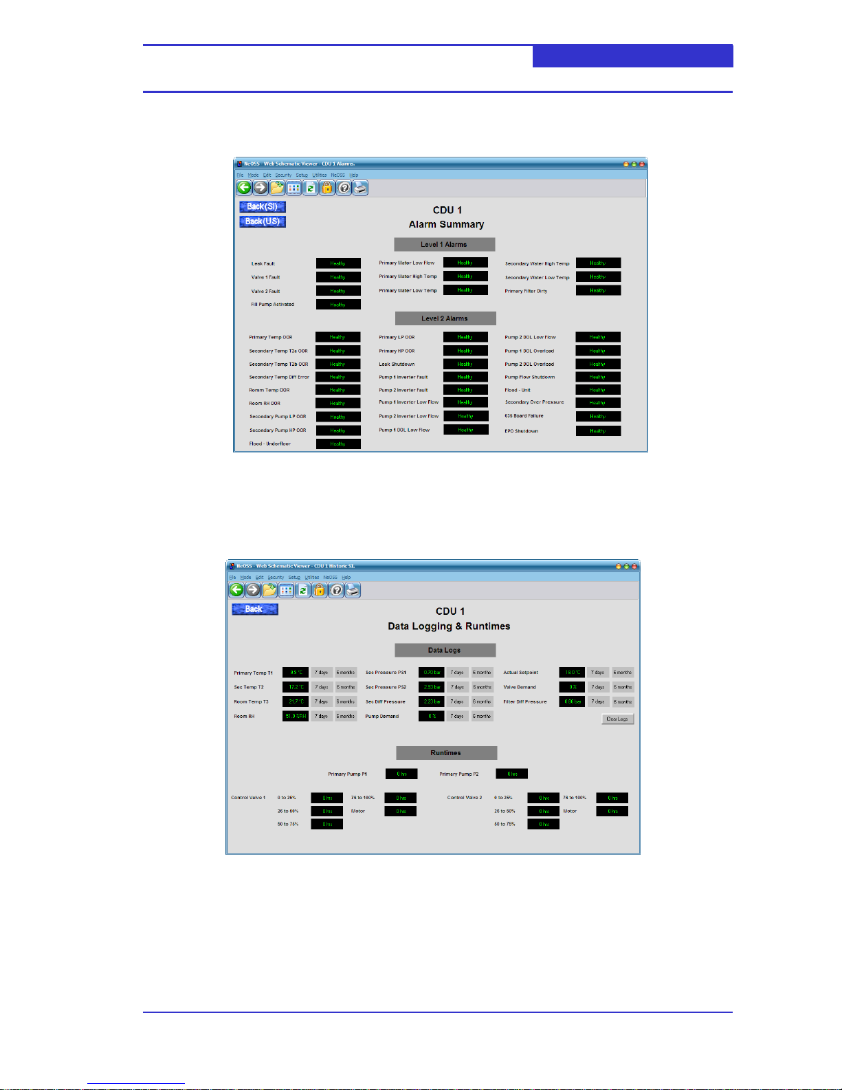
The alarms schematic lists all possible Level 1 and Level 2 alarms along with their current
status. The current status can be Healthy (no alarm), ACTIVE or ACTIVE –Deferred.
To view the historic alarm list please refer to section 6.4.
6.3.3 Historic
The Historic schematic provides access to historic data logs, in addition to indicating the run
hours of the pumps and valves.
Displaying a Datalog
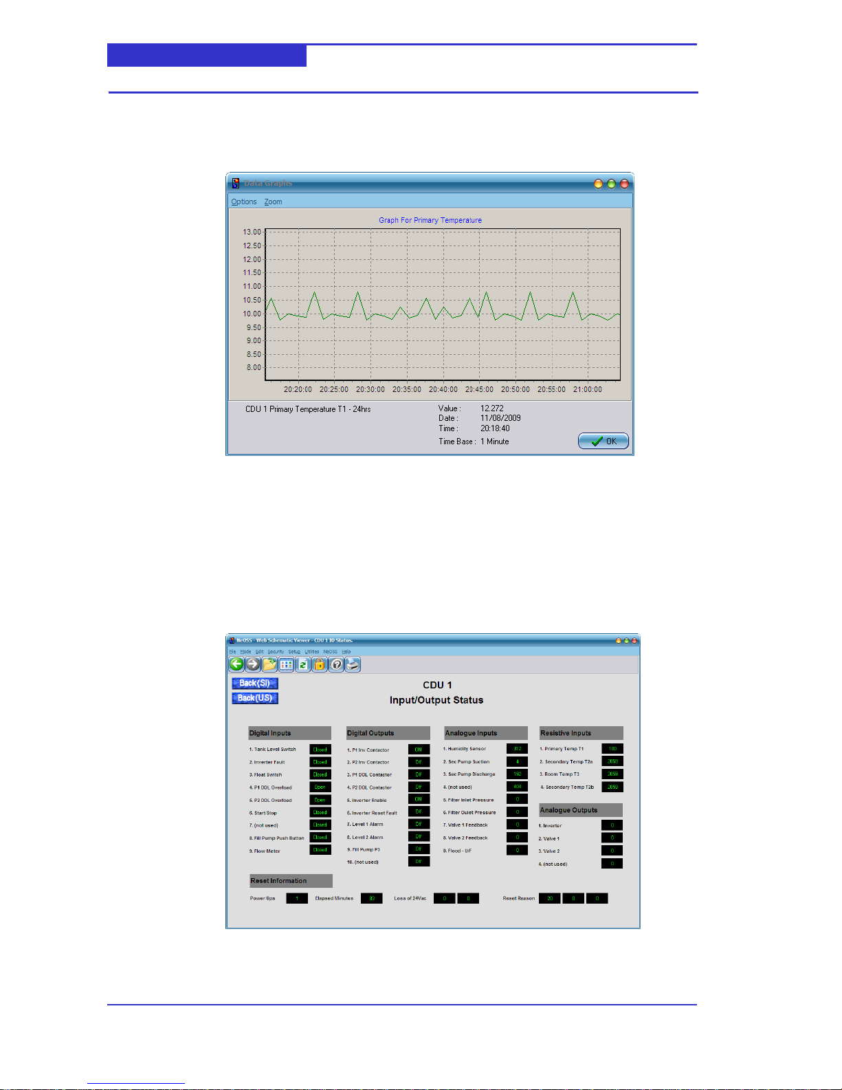
The datalog section provides access to historic trending data for a number of CDU data
points. For each data point the user may access one of three data logs,
- The last 24 hours, logged at 1 minute intervals.
- The last 7 days, logged at 5 minute intervals
- The last 6 months, logged at 15 minute intervals
Page 24
Web Server Installation Guide Page 24
CDU-AC5
Click on the current value to retrieve the 24 hour data log. Click on the 7 days button or the 6
month button to retrieve the 7 day and 6 month data log respectively.
The following screen illustrates a typically data log,
Saving a datalog to CSV
You may save the datalog values to a CSV file on your local hard disk. From the Data graph
menu select Options->Export Data.
6.3.4 Input/Output Status
The I/O Status schematic provides all CDU low-level hardware input and output values for
diagnostic purposes. In addition, the `reset info’ is displayed towards the bottom of the
screen.
Page 25
Web Server Installation Guide Page 25
CDU-AC5
Digital Inputs
Displays the current state of each of digital input. The state can be either Open (circuit) or
CLOSED (circuit).
Digital Outputs
Displays the current state of each of digital output. The state can be either Off or ON.
Analogue Inputs
Displays the current state of each of analogue input. Each input is able to accept a signal in
the range of 0V to 18V or 0mA to 36mA. For inputs 1 to 4, this input range corresponds to 0
to 4096 bits. For inputs 5 to 9, this input range corresponds to 0 to 1024 bits.
Resistive Inputs
Displays the current state of each of resistive input. The value displayed is in multiples of
100ohms. E.g. 61 = 6k1ohms.
Analogue Outputs
Displays the current state of each of analogue output. Each output is specified as 0 to 10V –
corresponding to a displayed value of 0 to 255.
6.3.5 Parameters
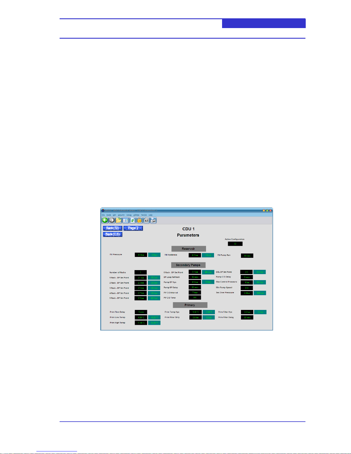
The two parameter schematics (Parameters – Page 1 and Parameters – Page 2) provide
access to all CDU parameters. You may adjust parameters if you have sufficient user account
privileges.
Whilst the CDU is configured to operate according to either the SI or IMPERIAL parameter
set, the CDU-AC5 displays both sets simultaneously. The current active set is displayed
towards the top right of the parameter schematics,
Adjusting Numerical Parameters
Click on the current value of the required parameter. A dialog will be displayed,
Page 26

©2010 Coolcentric, A Division of Vette Corp Part # 109745 Rev A
CDU-AC5
Using the mouse, enter the new value and click Enter.
Adjusting Option Parameters
Click on the current value of the required parameter. A dialog will be displayed,
Click on the drop-down button and select required option. Click OK
6.4 Displaying the Alarm List
From the Menu, select NeOSS -> Alarms
A window will be displayed as follows,
The alarm list can be filtered to display only alarms from a specific CDU by selecting the
appropriate filter in the left-hand pane.
 Loading...