

Page 1

Instruction Manual
NVR with Gateway
Thank you for your support
Please read the instruction manual carefully before operation.
*
Please keep the instruction manual for future reference.*
Page 2

Product Introduction-------------------------------------------------------------------3
Product functions ----------------------------------------------------------------------3
Alarm function-------------------------------------------------------------------------3
NVR Function-------------------------------------------------------------------------4
Restore to Factory Default Settings -----------------------------------------------------4
Technical Parameters-------------------------------------------------------------------4
1. Product hardware--------------------------------------------------------------------5
1.1 Product configuration---------------------------------------------------------------5
1.2 Product connection-----------------------------------------------------------------5
1.3 Hard disk installation ---------------------------------------------------------------6
2. APP download ----------------------------------------------------------------------6
3. Add NVR Gateway------------------------------------------------------------------6
3.1 Product information ----------------------------------------------------------------7
3.2 The step to add NVR Gateway-------------------------------------------------------7
3.3 NVR Gateway Mode---------------------------------------------------------------8
4.Add Sensors ------------------------------------------------------------------------8
4.1 Enter the interface of Add Sensors -------------------------------------------------8
4.2 Add Contact Sensor--------------------------------------------------------------9
4.3 Add Power Plug-----------------------------------------------------------------10
4.4 Add PIR Motion Sensor----------------------------------------------------------11
4.5 Add Smoke Sensor- -------------------------------------------------------------12
4.6 Adding siren alarm--------------------------------------------------------------13
4.7 Add SOS ------------------------------------- ---------------------------------14
4.8 The sensor linkage ----------------------------------------------------------------15
4.9 Deleting sensor -------------------------------------------------------------------16
5. Adding IP Camera------------------------------------------------------------------16
5.1 Teaching Steps------------------------------------------------------------------16
5.2 Camera Other Operation---------------------------------------------------------17
5.3 Video Monitoring Picture--------------------------------------------------------18
5.4 Camera Wireless Install----------------------------------------------------------19
6. Recording-----------------------------------------------------------------------------------------------20
6.1 Enter the video interface---------------------------------------------------------20
6.2 View recording------------------------------------------------------------------20
Table of Contents
1
Page 3

6.3 R ecording Settin g-- -- -- ----- -- ----- -- ----- -- ----- -- ----- -- ----- -- --21
7. Ala rm event ---- -- ----- -- ----- -- ----- -- ----- -- ----- -- ----- -- ----- -- ---21
8. Setting- -- ----- -- ----- -- ----- -- ----- -- ----- -- ----- -- ----- -- ----- -- ----2 2
8 .1 Ent er the sett ing interfa ce- -- ----- -- ----- -- ----- -- ----- -- ----- -- -- --- 22
8 .2 M odi fy a lar m ho st i con -- --- -- -- ----- -- ----- -- ----- -- ----- -- ----- -- --22
8. 3 Othe r se tting s-- -- ----- -- -- --- -- -- --- -- -- --- -- -- ----- -- ----- -- ----- -23
9. Dev ice in for mation -- -- --- -- -- --- -- -- ----- -- ----- -- ----- -- ----- -- ----- 24
10.NV R- -- ------- -- -- -- -- -- ----- -- -- -- -- -- ------- -- -- -- -- -- ----- -- -- -- -2 4
10. 1NV R fu nct ion -- ----- -- ----- -- ----- -- ----- -- ----- -- ----- -- ----- -- --24
10.2 Lo g in ---- -- -- --- -- -- --- -- -- --- -- -- --- -- -- ----- -- ----- -- ----- -- ---25
11.Add de vices--- -- -- --- -- -- --- -- -- ----- -- ----- -- ----- -- ----- -- ----- -- --25
11 .1 Manu al Add -- ----- -- ----- -- ----- -- ----- -- ----- -- ----- -- -- --- -- -- --2 5
11.2Au tom ati c Add -- --- -- -- --- -- -- ----- -- ----- -- ----- -- ----- -- ----- -- -26
12.Syste m Set up- -- ----- -- ----- -- ----- -- ----- -- ----- -- ----- -- ----- -- ----- 27
12. 1 Device I nfo rma tion- ----- -- ----- -- -- --- -- -- --- -- -- --- -- -- ----- -- ---27
12.2 Netwo rk S etup- ----- -- -- --- -- -- --- -- -- --- -- -- ----- -- ----- -- ----- -- 27
13.Syste m Infor mat ion -- ----- -- ----- -- ----- -- ----- -- ----- -- ----- -- -- --- -- 28
13.1 B asic Se tti ngs - -- ----- -- ----- -- ----- -- ----- -- ----- -- -- --- -- -- --- -- 28
13 .2 Ti me Set --- -- -- ----- -- ----- -- ----- -- ----- -- ----- -- ----- -- ----- -- -28
13.3 Disk Man ageme nt - --- -- -- --- -- -- ----- -- ----- -- ----- -- ----- -- ----- -29
1 3.4 Sy stem M ainte nan ce ----- -- ----- -- ----- -- ----- -- ----- -- ----- -- ----2 9
14.Chann el I nfo rmati on - ----- -- ----- -- ----- -- ----- -- ----- -- ----- -- ----- -- 29
14 .1Dis pla y Set up- -- ----- -- ----- -- ----- -- ----- -- ----- -- ----- -- ----- -- -30
14.2 Video P ara meter ----- -- ----- -- ----- -- ----- -- ----- -- ----- -- ----- -- --30
14.3 Audio Pa ram eter- ----- -- ----- -- ----- -- ----- -- ----- -- ----- -- ----- -- -31
14.4 Recor din g Pl an- ----- --- --- ----- --- -------- --- -------- --- ----- --- --- ----- --- --- ---31
14.5 IP c han nel Se tup ----- --- --- ----- --- --- ----- --- -------- --- -------- --- ----- --- --- --32
15. Imag e S etu p ------ --- -------- --- ----- --- --- ----- --- --- ----- --- -------- --- -------- --- -33
16. Video Play bac k------- --- ----- --- --- ----- --- --- ----- --- -------- --- -------- --- ----- --- 34
17. Pan /Tilt co ntr ol------ --- ----- --- --- ----- --- -------- --- -------- --- ----- --- --- ----- --- 35
18. Si ngle I mage- --- -------- --- -------- --- ----- --- --- ----- --- --- ----- --- -------- --- ------35
19. 4 ima ges----- --- ----- --- --- ----- --- --- ----- --- -------- --- -------- --- ----- --- --- ----- --3 6
20. Dis play Me nu b ar- --- --- ----- --- -------- --- -------- --- ----- --- --- ----- --- --- ----- --- -36
Guara ntee- --- -- --- ----- ----- ----- --- -- --- ----- ----- ----- --- -- --- ----- ----- ----- --- -- --- --37
2
Page 4

Product Introduction
The N VR Gate way is a new intellige nt s ecu rity equipm ent with th e fu nction of
NVR and Alarm sys tem . The ala rm system includes NVR Gat eway, alarm sensor,
ala rm cont roller and alarm receiver. The dev ices se nd informa tion to each other via
spe cific radi o frequenc y. Diffe rent count ries or regio ns hav e diffe rent frequ enc y.
NVR Gateway is t he "br ain" o f the whole system. The NVR Gat ewa y rece ives a nd
pro cess the sign als from alar m sensor s and issues i nstruct ions to the al arm c ont roller
to co ntrol all l ink ed sensor s. The N VR Ga teway als o hav e the funct ion of NVR, it can
dis play l ive video and rec ord the video from the cameras . Wi th com binatio n of the
two func tions (Gateway and NVR), the syste m prov ide both function of alarm and
sur veillan ce simult aneousl y.
Product functions
Ther e are two functio ns for th e NVR Gateway; one is alarm fun ction, th e other i s
vide o recording.
Alarm function
*
The NVR Gatewa y wor ks as the “brain” of the whole alarm system. It connec ts wi th
the alarm sensor s, alarm controllers and alarm receivers vi a radio frequency. It takes
the responsibili ties of si gnal receivi ng, pro cessing and issuing in struction s.
*
Alar m sensors detect the alarm even t and send signals to NVR Gateway, gateway
cont rols the alarm rece ivers. ( Alarm sensor s include Door/Windows sensor, Smoke
sens or, PIR motion detection sensor)
*
Alar m contro llers can co ntrol th e alarm receive rs thro ugh the gatewa y. Alarm
cont roller inclu des SOS/Remote cont rol.
*
Alar m receivers is responsibl e for r eceiving the signal from the NVR Gateway, and
carr y out alarm outpu t functions. Alarm receivers inc lude Siren that put out alarm
soun d and Smar t Power Pl ug that tu rns off power.
NVR Function
*
The NVR Gateway is with NVR function.
*
There is a RJ-45 Ethernet port on the gateway, which is compatible with 10Mbps and
100Mbps Ethernet speed. It makes the data transmission between the cameras and
gateway smooth.
*
There is build-in RF antenna in the gateway, which can send and receive radio
frequency from the sensors.
*
With powerful integrated chip, the NVR Gateway supports 8 channel cameras video
signal input and one channel video playback. There is a SATA interface for external hard
disk (Max. 5T)
*
3
Page 5

There is a HDMI interface on the NVR Gateway which can connect with monitor or TV.
*
The maximum resolution of the video display is 1920×1080. With HDMI port, the video
from the cameras can be displayed on the HD monitor.
The NVR Gateway has a USB 2.0 interface for mouse and keyboard, which is used for
*
setting menu screen which include storage devices set up and copying files.
Restore to Factory Default Settings
There is a Reset button on the NVR Gateway, it can restore all the data to the default factory
setting. Please use with caution.
Note
When the NVR Gateway is being restored to factory settings, please make sure power source
is connected.
Technical Parameters
Loc al Previe w: Suppor t PTZ contr ol, multi-sp lit scree n
*
Video inpu t: 8 cha nne l
*
Video play back: 1 cha nnel
*
*
Man agement func tions: su pport adm ini stratio n and confi guration of cameras, di sks,
and p an/tilt .
*
Dis play reso lut ion
*
Video Reso lution
Eth ernet: RJ -45 inter fac e
*
Sup ported Pr oto col: HTTP /DHCP/IP/T CP/UDP/FTP /SM TP/PPPo E/U PnP
*
Mob ile phone m onitor: S upport iP hon e/iPad/ 3G phone/sma rt phone
*
Wire less rang e: 50m
*
Rad io freque ncy : 868. 4MH Z EU,908.4U SA; 921.4 MHZ ANZ; 869 .2MHZ RU
*
Har d disk inte rface: SATA×1,5T Max
*
USB p ort: USB 2.0×1
*
Pro duct size : 140(L) x 13 0(W) x 29mm (H)
*
Net w eight: 18 2g/pc
*
Pow er supply : DC 5V/2.0 A
*
Pow er Consum pti on: 5 Watts (Max )
*
Work te mperatu re: 0°C~40°C (32 °F~104°F)
*
Work hu midity: 2 0% ~ 85% no cond ensing
*
Sto rage temp era ture: -10 °C ~ 60° C (14° F ~140°F)
*
Sto rage humi dit y: 0% ~ 90% no condensing
*
Cer tificate: CE , FCC, R oHS
*
: 192 0×1080,12 80× 720
: 128 0×720,6 40× 352
4
Page 6
1.Product hardware
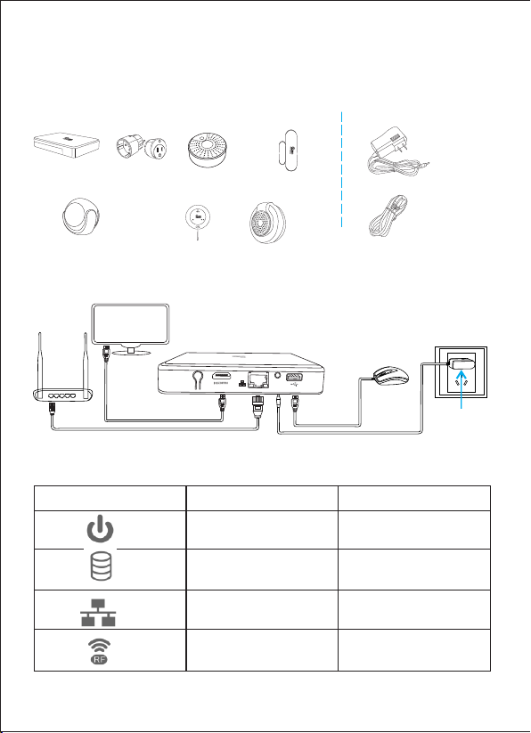
1.1 Pro duct co nfigu ra tion
NVR Gateway Power plug Smoke sensor Contact sensor
Product accessories
Power Adapter
Motion sensor (PIR) Remote control Siren alarm
SOS
1.2 Product connection
Please ref er to the photo as bellow when connecting de vice s
Monitor
Router
Reset
HDMI cable
Network cable
Please check the NVR Gateway if the indicators are in a normal state
Indicato r
Power indicator
Hard disk Blinking after instal lation
Internet cable port indi cator
RF indicator
DC 5V
Power Adapter
Type
Network Cable
Mouse
Power adapter
Normal sta te
ON
Blinking
Blinking, blinking
faster while pairing
5
Page 7
Please check if you connect th e devices in a right way if the indicators show abnormal ly.
Note
If you do not use the monitor, then don't need to connect the monitor and mou se, which
won't affect the NVR Gateway working.
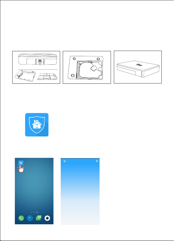
1.3 Har d disk inst allat io n
1.Remove t he ba ck cove r
Ope n here
2.Instal l har d disk
3.Clo se th e cover
2. APP download
*Us ers can download directly from website. iOS device downlo ad “Coolcamk its “on
APP store, Android devic e downl oad “Co olcamkits ” on Googl e play sto re.
The icon is shown as bello w:
Coo lcam ki ts
3.Add NVR Gat eway
Click Cool cam k its ico n Enter Cool cam k its int erf ace----
6
Page 8
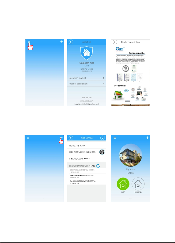
3.1 Pro duct in forma ti on
Click Coolca m kits icon and Coolcam kits interface will appe ars. Click the icon on the
upper left corner, the interface will displ ay the basic information about the product
operation manuals an d produc t brochures.
3.2 The step to add NVR Gateway
Click Coolcam kits icon, Coolcam kits interface will appears, click add icon on the upper
right corner. On NVR Gateway interface, input the basic information about NVR Gateway
and click OK.
Note
1.The default password of NVR Gateway is: admin
2.When adding NVR Gateway on the mobile phone, the smart phone must in the same network
with NVR Gateway, otherwise it is unable to find NVR Gateway.
7
Page 9
3.When you add NVR Gateway ID, please confirm whether the NVR Gateway UID numbers
is the same, otherwise please re-add the UID number.
4.Smart phone app support adding multiple NVR Gateway.
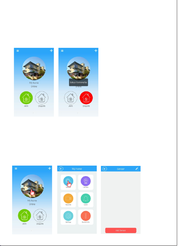
3.3 NVR G ateway Mo de
Alarm host m ode “ Armin g” an d “di sarmi ng”
Arming: in arming condi tion , all devices conne cted to the NVR Ga tewa y can be li nked
through th e NVR Gat eway.
Disarming: in disarming con dition, al l devices con nect ed to the NVR Gate way ca n be
disconnected throu gh NVR Gateway
Note: SOS can be link ed with NVR Gateway in any cond itio n.
4.Add Sensors
4.1 Enter the interface of Add Sensors
Click NVR Gateway Click Device Click Add Sensors
8
Page 10
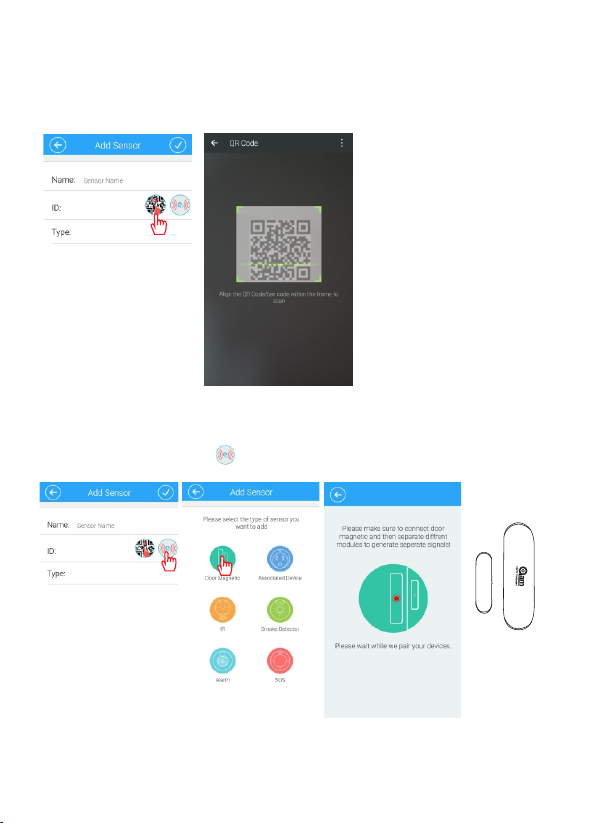
4.2 Add Co ntact Sen sor
a.
Scan QR Code t o add t he Cont act s ens or
Click Add Sen sor s Click QR cod e as be low to add sen sor
b.Add Contact sensor via mating code
Click “Add sensors” Click Click “Contact sensor” “ ”
9
Page 11
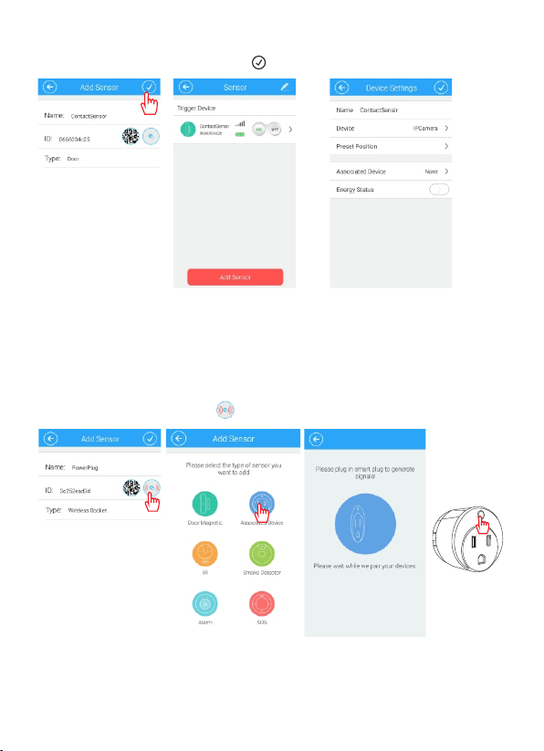
b.Input the name of the sensor Click“ ”
Note
1. After addin g the sen sor ID, please conf irm whether this ID nu mber is as same as the
ID num ber printed on sensor. If not, pleas e add aga in.
2. The NV R Gateway can add 10 con tact sensors at most.
4.3 Add Po wer Plu g
a.Click “A dd Se nsor” C lic k --- Click “P owe r Plug” “ ”
10
Page 12
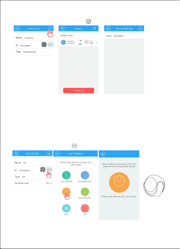
b.Input th e nam e of the se nso r Cli ck“ ”
Note
1.Aft er adding the sensor ID, please con firm whether th is ID numb er is as same as the
ID number prin ted on sensor. If not, pl ease add again.
2.The method of Add Power plug by scan QR code is the same as Contact sensor, please
refe r to 4.2.
3.The NVR Gatew ay can add up to 10 pcs power plug.
4.4 Add PI R Motion Se nsor
a.Click “A dd Se nsor” C lic k --- Click “P IR” “ ”
11
Page 13

b.Input th e sen sor nam e Cli ck“ ”
Note
1. After adding the sensor ID, please confirm whether this ID number is as same as the ID
number printed on sensor. If not, please add again.
2. The method of Add PIR by scan QR code is the same as Contact sensor, please refer to 4.2.
3.The sensitivity of PIR covers area of PIR detection, only within the detection area,
PIR can be triggered, beyond the range of PIR detection, PIR will not be triggered.
4.The gateway can add up to maximum 10 pcs PIR.
4.5 Add Sm oke Senso r
a.Click “A dd Se nsor” C lic k --- Click “ ” “ ” Smo ke Sens or
Press code button for
matching code
12
Page 14

b.Input th e nam e of Clicksensor “ ”
Note
1. After adding the sensor ID, please confirm whether this ID number is as same as the ID
number printed on sensor. If not, please add again.
2. The method of Add Smoke sensor by scan QR code is the same as Contact sensor, please
refer to 4.2.
3.The gateway can add up to maximum 10 pcs Smoke sensor.
4.6 Addi ng sire n alarm
a.Click “A dd Se nsor” C lic k --- Click “S ire n alarm ” “ ”
Click the inside of alarm
button for coding
13
Page 15

b.Input th e nam e of Clicksensor “ ”
Not e
1. After add ing the sen sor ID , ple ase co nfi rm whethe r this ID number is a s same as the
ID nu mber prin ted on sens or. If no t, ple ase add aga in.
2. The meth od of Add Siren Alarm by s can QR code is the sa me as Co ntact sen sor,
ple ase refer t o 4.2.
3.T he siren al arm can be manual ly controlle d to trigge r alarm.
4.Th e NVR Ga tew ay can add up to 2 siren alar ms.
4.7 Add so s
a.Click “A dd Se nsor” C lic k --- Click “s os” “ ”
SOS
Click the button of
sos to match code
14
Page 16

b.Input th e nam e of Clicksensor “ ”
Not e
1. Afte r adding th e sens or ID, plea se con firm whet her th is ID numbe r is as same as the
ID number p rinted on senso r. If not , plea se add again.
2. The m ethod of Add SO S by sca n QR cod e is the s ame as C ontact sensor, p lease
ref er to 4. 2.
3.Th e gate way can add up to 10 pcs SOS.
4.8 The sensor linkage
There are two functions for sensor linkage, one of them is actively link others sensor work,
this device is called as triggered device, including PIR, door contact, smoker sensor and
SOS; the other is passively accept the linkage message which alarm host send, including
power plug, microphone and IP camera.
The linka ge settin g of triggered device
The li nkage sett ing of contact sensor-- -Enter the conta ct sensor interface---Cl ick the
cont act se nsor
15
Page 17

Pay attention
1.Wh en set ting link age siren alarm , you wo uld set sir en ala rm linkag e turn o ff/o n.
whe n the li nkage swi tch tu rn on, once the trigger ed device t hat co nnectin g with alar m
hos t is tri ggered, t he sir en alarm will be trigge red alarm ; when the linkag e swit ch turn
off, any trigge red devic e that c onnecti ng wit h alarm hos t is tri ggered, the sir en alarm
won 't be tr iggered a larm.
2.An y trig gered dev ice can set the linkage s etting of power p lug.
3.Th e sire n alarm and power p lug tu rn on/off di spl ay the d evice turn on/o ff.
4.9 Del eting sen sor
Cli ck “Edi t”, ent er the ed iting i nterf ace and s elect s ensor w hat you n eed del ete, cl ick “de lete”
Ok bu tton
Del ete but ton
Note: D ele te an d the cli ck OK , the n exit th e edi tin g inter fac e.
5. Adding IP Camera
5.1 Teach ing Ste ps
Click My hom e ico n ---Cl ick c ame ra icon - --C lic k addin g cam era i con
1
16
Page 18

Type i n cam era bas ic in for matio n-- -Click con fir med
Note:
1.The method of add ing camera UID is same as adding gateway, please refer step in 3.2
Camera default pa ssword : admin
2.To avoid unauthorized acc ess, please change passwo rd when accessing the camera fo r
the first time.
3.The camera can be added to NVR Gat eway only when both are under same ne twork.
4.Up to eight camer as can be added to each NVR gateway。
5.2 c ame ra ot her operation
By pr essing ca mera butt on and hold , following se t up can b e changed : delete ca mer a,
rev ise ca mer a name, rev ise secur ity password a nd cancel t his funct ion ”
Lon g pres s-- -select appr opriate devi ce
17
Page 19

Click to ren ame C lick to r evi se pa sswor d Cli ck to d elete c ame ra
5.3 Vide o Monitor ing Pic ture
Click came ra to e nter video m oni torin g pic tur e
Function B utt ons
Speaker
Capture
View
Presetti ng
PIR
Verti cal Fli p
18
Horizontal Flip
Resoluti on
Scene
Page 20

5.4 Camera Wire le ss Install
Click came ra- --Cli ck in sta ll--- Cli ck wi fi admi nis tra tion
Select wif i, en ter pas swo rd an d click c onf irm ed, ins tal l fin ished
Note
For initial setup of came ra, customer should make connection between camera and WiFi
router by using one key setup on ca mera app separately. Once WiFi connection is made
between the camera and wifi router, the NVR gateway can search network and add the
camera automatically o r man ually. The camer a can be added to the NVR gateway by
scanning QR code as well.
19
Page 21

6. Recordi ng
6.1 Ent er the vi deo int er face
Click “Ala rm ho st” ico n cli ck “R ecord ing ” ico n enter t he vi deo i nterf ace
6.2 View recording
Clic k “video event” icon---ch oose th e IP camera that you want to vie w---view event
20
Page 22

6.3 Recording Setting
1). Ente r record setting interface
Click “Record setting” icon, and then
enter recording setting interfa ce
Note
Full-time recording recor ds the vi deo 24 ho urs a day
*
Video se ttin g plan me ans choosing part-time to video
*
Full-time recording and part-time reco rding funct ion can not be use d at the same time
*
2). Video setting plan
Slide the “On/Off” key to open video setting plan,
then click recording date to set the video time.
7. Alarm event
Click “Alarm host” ico n---click “Event” icon---e nter event interface, then click “Search”
icon to search alarm event according to time
21
Page 23

8. Setting
Click “Setting” icon, there are “Alarm host icon setting”, “Password setting”, “Alarm
push function setting”, “Alarm recording setting” ,“Push sound setting” ,“Clock setting”,
“Format disk setting”, “Restart host setting”
8.1 Enter the setting interface
Click “alarm host” icon---click”event” icon---enter “setting” interface
8.2 Modify alarm host icon
Clic k “alarm host” icon, then you can choose taking phot o or addin g a local image
”
22
Page 24

8.3 Oth er sett ings
Password s ett ing Push sound s ett ing Clo ck se tti ng
Format dis k set ting Re sta rt al arm hos t
Note
when format disk and restart alarm host, please do not power off , so as to prevent the
alarm host from damaging
23
Page 25

9. Device information
Click “Alarm host” icon--- click “Device informa tion” ic on ---view “Device information”
10.NVR
Please refer to “1.2 Product Connection Way” from Page 6, To connect all devices including
Display Screen and Mouse. Then choose interface channel Of HDMI video signal you access,
enter into video monitoring interface.
10.1NVR function
Please click right button of Mouse on NVR interface, Menu bar come out, Users can operate
Single image, 4 images, 9 images, Pan-Tilt control, System setup, Video playback, image setup,
IP channel setup, log in, display function options of Menu bar
24
Page 26

10.2 Lo g in
User name: a dmi n Passw ord : adm in
11.Add devices
There is “Automation” and “Manual operation” in IP channel of Menu bar for users to add
cameras, P lease check “filter equipment has been added”, Avoid to repeat to add device.
11.1 Manual Add
Choose Camera, click add button, enter password to add device.
25
Page 27

Click add bu tto n, ente r pas swo rd of cam era
Users can ad d 8 cam eras fo r fin al in terfa ce
11.2Automatic Add
Users can add devices randomly and automatically in LAN, if NVR has connected with other
devices, please click automatic add, but please note that IP address of camera might change.
26
Page 28

12.System Setup
There is “Device in formation” “Network in formation” “System inf ormation” “Channel
informatio n” in system setup column
12.1 Device Information
Users can see device name, device type, software version, disk amount, channel amount,
UID number in devic e information column
12.2 Network Setup
Users can set up IP addre ss of devic e and DNS as well as HTTP port in network column.
.
27
Page 29

13.Syste m Information
There is “Ba sic S ettin gs” “ Time Set ” “Di sk Ma nagem ent ” “System Ma int enance” in
system inf orm ation c olu mn.
13.1 Ba sic Setti ngs
Users can re vis e the nam e of Se tup , choos e Lan gua ge (Chi nes e/E nglis h), C hoose
Resoluti on in B asic se tup c olu mn.
13.2 Time Se t
Users can se t up ti me of dev ice a nd ch oose ti me zo ne.
28
Page 30

13.3 Di sk Manage ment
Users can ch eck s tatus o f dis k and f ormat t he da ta of d isk.
13.4 Sy stem Main tenan ce
Restart an d Res et butt on in S yst em Main ten anc e.
14.Ch annel Inf ormat io n
There is “Di spl ay Setu p” “Vi deo P ara meter ” “Au dio Parame ter ” “Recordi ng Pl an”
“IP Chan nel S etup” i n Cha nne l infor mat ion c olumn .
29
Page 31

14.1D isplay Se tup
Users can ch oos e chann el in d isp lay set up co lum n Displ ay ti me an d displ ay na me
14.2 Video Parameter
In Video Parameter column, we can choose Resolution(1280X720P/650X352),Data rate,
frame rate, video coding control.
30
Page 32

14.3 Aud io Parame ter
Volum e ran ge from 1-10 0
14.4 Re cording P lan
In recordi ng pl an colu mn, u ser s can cho ose v ide o recor din g fil e time, c hoo se video
recordin g cha nnel, c hoo se pl annin g vid eo re cordi ng da ta ra te, cho ose t ime setup fo r
video reco rdi ng.
31
Page 33

Recordin g Sch edule S etu p
14.5 IP ch annel Set up
Click sear ch bu tton, c hoo se de vice, e nte r pas sword o f dev ice t o add dev ice , Original
password o f dev ice is ad min .
32
Page 34

15. Image Se tup
Image setu p col umn dis pla y Vertical f lip , horizont al im age, br igh tne ss, Sat ura tio n,
contrast r ati o and Chr oma .
33
Page 35

16. Video Playback
On vi deo playback m enu , choose da te, c han nel and vid eo ty pe, it will d isp lay video
fil e in correspon din g cha nnel. Use r can p lay, pa use , slow play bac k and fast- for war d.
Vide o file co lor d isp lay
Planning Video Reco rdi ng Ala rm Vid eo Re cordi ng Manual Video Record ing
34
Page 36

17. Pan/Tilt control
On NV R interface, choos e dev ice a nd cl ick r igh t but ton to choose Pan/Til t con tro l in
men u bar. User c an co ntrol the directio n, zo omi ng an d foc usi ng of t he camera.
18. Single I mage
Users can ch oos e each ch ann el as s ingle i mag e
35
Page 37

19. 4 images
Users can ch oos e chann el 1 to 4 a s qua d image o r cha nne l 5 to 8 as qua d ima ge.
20. Display Menu bar
Click Display Menu bar to display function opetion on the upper left corner of interface .
36
 Loading...