

Page 1

2018 © Store It Cold, LLC. Rev 2018-9a All Rights Reserved.
COOLER CONSTRUCTION GUIDE
Page 2

2018 © Store It Cold, LLC. Rev 2018-9a All Rights Reserved.
COOLBOT WALK-IN COOLER
SHIPPING AND WARRANTY INFORMATION
SHIPPING
Please read carefully this document regarding your shipments for instructions on receiving,
inspecting, and filing claims if necessary.
• Your CoolBot Cooler System will be delivered in ONE shipment which includes:
1. Enclosure (Walk-in box)
2. A/C unit
3. CoolBot Temperature Controller
• You will be provided with shipment information and estimated delivery times.
• Our Walk-In enclosure manufacturer and our A/C supplier take every precaution for safe
arrival, but their responsibility ceases when shipment is turned over to the carrier.
• The walk-in cooler will be transported and delivered on a semi-truck. The receiver will be
responsible for providing appropriate access to the delivery vehicle and all necessary
equipment (or man power) to safely unload the pallets from the carrier.
• The receiver will be responsible for ensuring a solid surface for unloading the pallet where it
can be rolled out of the lift gate and be left on the ground.
Page 3
2018 © Store It Cold, LLC. Rev 2018-9a All Rights Reserved.
IMPORTANT!
INSPECT SHIPMENT IMMEDIATELY UPON ARRIVAL FOR LOSS OR DAMAGE. LOOK FOR TEARS ON
THE PLASTIC WRAPPING, DENTS, CUTS, OR ANY VISIBLE DAMAGE ONCE THE LOAD IS ON THE
GROUND BEFORE IT MOVES IN TO YOUR LOCATION AND BEFORE YOU SIGN THE RECEIPT.
PLEASE WRITE ANY DAMAGES AND/OR DISCREPANCIES ON BILL OF LADING BEFORE SIGNING
AT THE TIME OF DELIVERY AND TAKE PHOTOS OF THE LOAD FROM EVERY SIDE TO SUPPORT
YOUR CLAIM.
If concealed loss or damage is discovered later, notify your Store It Cold representative and
submit pictures of the damage.
IMPORTANT!
AIR CONDITIONER
INSPECT A/C IMMEDIATELY UPON ARRIVAL FOR DAMAGE. LOOK FOR TEARS OR CUTS, OR ANY
VISIBLE DAMAGE ON THE BOX ONCE THE A/C HAS BEEN UNLOADED AND BEFORE YOU SIGN
THE RECEIPT. IF THERE IS ANY NOTICEABLE DAMAGE REFUSE THE DELIVERY AND CONTACT US
IMMEDIATELY TO ARRANGE FOR DELIVERY OF A REPLACEMENT UNIT.
CAREFULLY OPEN YOUR A/C WITHIN 24HR AND INSPECT FOR CONCEALED DAMAGE AND FOR
MISSING CONTENTS. IN CASE OF CONCEALED DAMAGE OR MISSING PARTS, DO NOT PLUG IN
YOUR UNIT. PLEASE TAKE PICTURES AND NOTIFY US WITHIN THE 24HR PERIOD SO WE CAN
HAVE A REPLACEMENT A/C BE DELIVERED.
Page 4

2018 © Store It Cold, LLC. Rev 2018-9a All Rights Reserved.
WARRANTY
ENCLOUSURE 10 YEAR LIMITED WARRANTY
The enclosure (Walk-In box) manufacturer warrants to the original purchaser that this preengineered wall, ceiling, and floor (if applicable) panels purchased from SIC, are free from
defects in material and workmanship for a period of ten (10) years from the date of original
shipment under conditions of normal use and service at the original installation site.
Component parts, hardware and accessories are warranted for a period of one (1) year from
date of shipment.
THIS WARRANTY IS NON-TRANSFERABLE
The obligation of the Manufacturer under this warranty shall be limited to repairing or
replacing, at the company’s discretion, the panels that prove to be defective within ten (10)
years of purchase, FOB factory. All hardware and accessories carry a standard one year
warranty. The standard warranty does not include any labor charges for repair or replacement
of defective parts. In no event, shall SIC be liable for loss of use, revenue or profit, or for any
other indirect, incidental, special, or consequential damage including, but not limited to, food
spoilage or product loss.
SIC expressly disclaims and makes no warranties, express or implied, as to the condition, design,
utility, quality, adequacy, or capacity with respect to any standard or non-standard product,
including, without limitations, any warranty of merchantability or fitness of such product for a
particular purpose or intended use.
This warranty is in lieu of all other warranties expressed or implied and does not apply to
equipment which has been subject to any accident, alteration, abuse, misuse, alterations by
unauthorized service, improper installation or installation by an unlicensed contractor.
Exclusions from Warranty Coverage:
• Labor, mileage or other costs incurred for repairing, removing, installing, shipping,
servicing, or handling of defective or replacement panels or parts.
• Normal maintenance or repairs
• Damage or delays occurring in transit
• Damage or loss of product, property, income or profit
• Floor panels subjected to wet mopping, flood, water leak, pallet jacks or weight
exceeding 600 lbs/sq ft
• Damage by fire, flood, earthquake or natural disasters
Page 5
2018 © Store It Cold, LLC. Rev 2018-9a All Rights Reserved.
A/C UNIT 1 YEAR LIMITED WARRANTY
Your A/C unit carries a 1 Year limited warranty. Please contact SIC to facilitate a warranty
claim of your A/C unit during this period.
IMPORTANT! Please refer to the OWNERS’S MANUAL of the A/C unit to follow
recommendations about proper installation, operation, and maintenance of your A/C unit.
This warranty will NOT cover claims due to improper installation or improper electrical supply
to the A/C unit.
COOLBOT DIGITAL CONTROLLER 1 YEAR LIMITED WARRANTY
DISCLAIMER: By using the CoolBot temperature controller, you (the “User”) acknowledge there
are inherent hazards in getting an air-conditioner (“A/C”) to do something it was not originally
designed to do, and that these inherent hazards cannot be ameliorated, mitigated or obviated
while still maintaining the essential functionality of the CoolBot. User accepts all responsibility in
the use of and monitoring of the CoolBot and A/C. User assumes all risk of loss of property or
product due to improper functioning of the CoolBot (or A/C). User assumes all risk of injury and
warrants that he/she will defend, indemnify and hold the seller harmless for any direct or
consequential harm or damage that may result from the use of this product.
LIMITED WARRANTY: CoolBots are warranted against defects for 1 year, not including damage
due to misuse or accidents. To double the warranty on your CoolBot see page 19 of the CoolBot
Installation Manual.
ALL COOLBOT WALK-IN COOLER SALES ARE FINAL INCLUDING ALL ITS COMPONENTS -
ENCLOSURE, A/C UNIT AND COOLBOT DIGITAL CONTROLLER.
Page 6
2018 © Store It Cold, LLC. Rev 2018-9a All Rights Reserved.
ENCLOSURE INSTALLATION INTRUCTIONS
Enclosed with the Installation manual there is a Set-up drawing, showing the identification
and proper placement of your walk-in cooler panels.
IMPORTANT
YOUR WALK-IN COOLER PANELS, DOOR, SCREEDING OR OUTDOOR PACKAGE PARTS MIGHT
DIFFER IN DESIGN OR LOOKS FROM THE ONES SHOWN IN THIS MANUAL.
Having a SUCCESSFUL INSTALLATION begins with having a level floor. If the floor is not level,
it will be necessary to install shims, under each floor panel cam-lock.
If the Walk-in does not have Floor Panels, then install shims under the Walk-in's Vinyl screed.
A minimum of 2" clearance between existing building walls and Walk-in is necessary for
proper air circulation.
Page 7
2018 © Store It Cold, LLC. Rev 2018-9a All Rights Reserved.
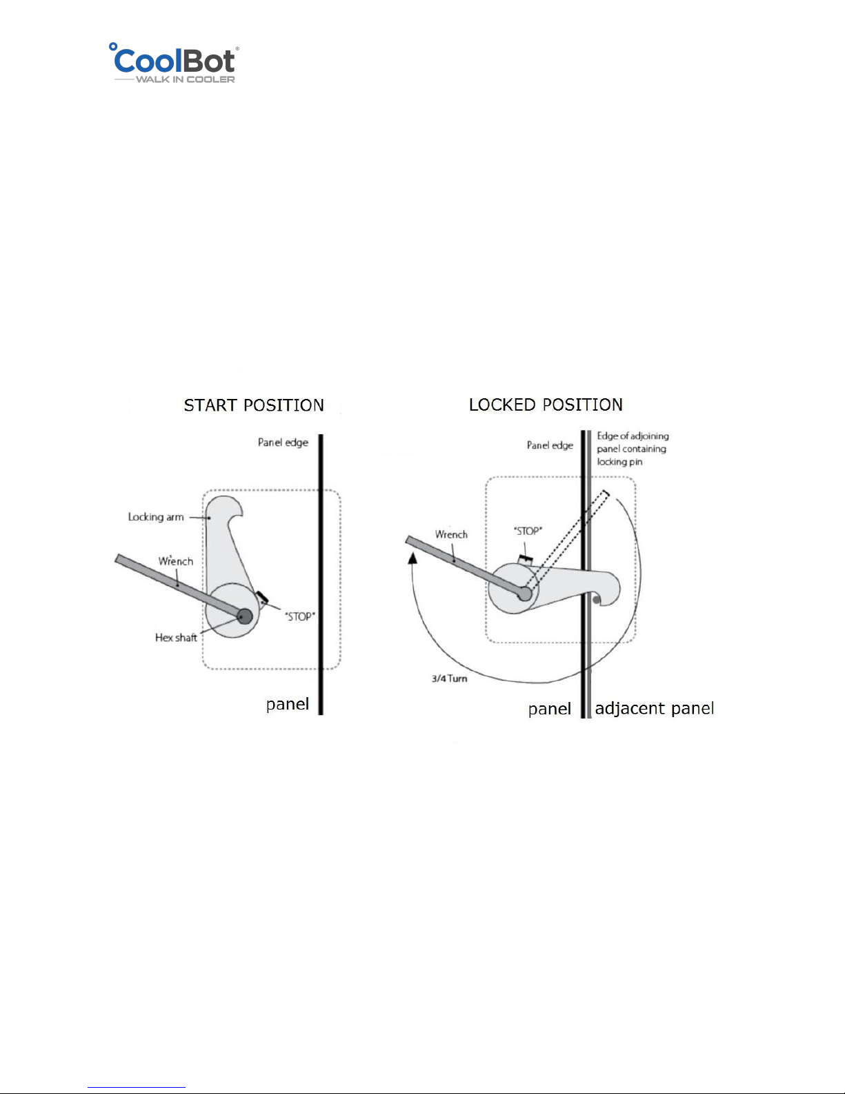
CAM-LOCK MECHANISM
Before starting to put your enclosure together, familiarize yourself with the operation of the
Cam-lock mechanism.
Locks will be on the right side of the panel and they operate in a clockwise rotation to lock.
They are accessible through the small holes on the right side of the panel.
Insert the Hex Wrench provided with your Installation package, and after the panels have been
carefully aligned, turn approximately ¾ of a full turn until panels are securely locked together.
DO NOT OVERTGHTEN! It will strip the Hex hole and damage the mechanism.
DO NOT drive the Hex Wrench with a hammer as this can damage the lock.
This locking mechanism is reversible. Simply rotate in the opposite direction to release the lock
and make adjustments. Don’t forget to lock your panel again after adjustments have been
made.
Page 8
2018 © Store It Cold, LLC. Rev 2018-9a All Rights Reserved.
WALK-IN INSTALLATION WITH A FLOOR OPTION
YOUR WALK-IN COOLER PANELS, DOOR, SCREEDING OR OUTDOOR PACKAGE PARTS MIGHT
DIFFER IN DESIGN OR LOOKS FROM THE ONES SHOWN IN THIS MANUAL.
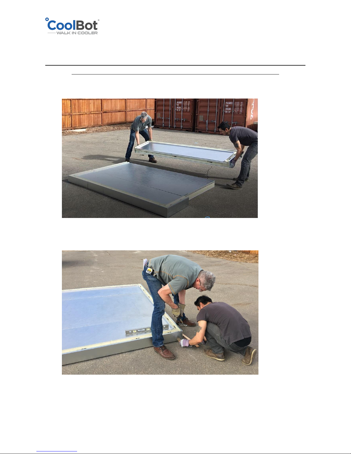
1. Set the floor panels according to the Set-up drawing included in your documentation.
All panels have labels, and are identified in the Set-up drawing.
2. Make sure that all floor panels are level. If not, using shims under cam-locks of the floor
panels around the outside edge is suggested to level the floor.
Page 9
2018 © Store It Cold, LLC. Rev 2018-9a All Rights Reserved.
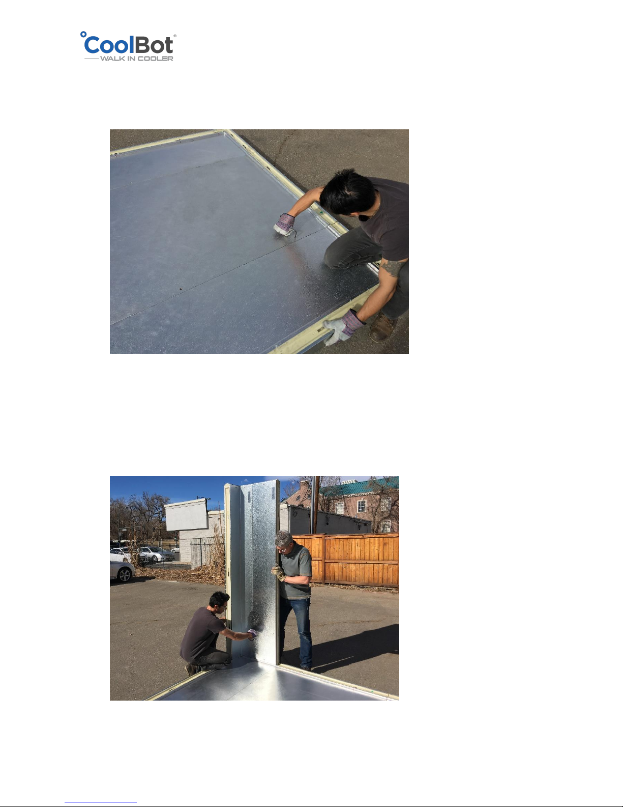
3. After all floor panels are level, firmly and securely lock all floor panels together with the
Hex Wrench provided in your installation package. Turn it approximately ¾ of a full turn
and repeat until all floor panels are securely locked together.
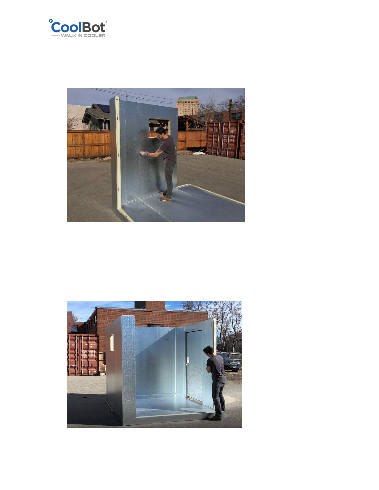
4. Begin with two corner panels. Usually the left back corner is a good place to start. Make
sure that the top of each wall adjacent panel is flush with each other. Use the wrench to
secure the wall panels to the floor and then lock the wall panels together to start the
wall. Check for alignment to make sure the panels are flush with the floor, corners and
each other as you proceed.
Page 10
2018 © Store It Cold, LLC. Rev 2018-9a All Rights Reserved.
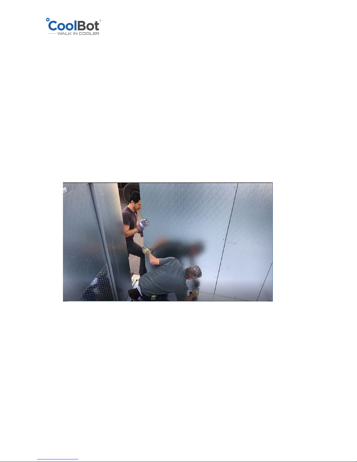
5. Select the next adjacent wall panel, going in a clockwise direction around the perimeter
and follow the same steps as above: Align, lock to the floor, lock to the adjacent wall
panel and double check for alignment making sure panel is flush on all sides and on top
with the adjacent panels and floor.
6. Repeat this procedure with each wall panel working your way around the perimeter of
the cooler in a clockwise fashion.
7. When installing the Door panel, DO NOT REMOVE THE DOOR FROM DOOR FRAME.
Follow the same recommendations as when installing the wall panels. Door frame panel
must be LEVEL and PLUMB. Ensure it is flush at the top with all adjacent panels. DO NOT
screw-in the door threshold yet.
Page 11
2018 © Store It Cold, LLC. Rev 2018-9a All Rights Reserved.
TIPS FOR PROPER DOOR INSTALLATION
• Level and plumb door frame and frame legs are level to each other. Shim under
door frame or floor to achieve level and plumb.
• Frame legs are to be in plane with each other. Check with 4’ straight edge across
door face at bottom of doorway.
• Frame legs are parallel and not spread out. Opening width at bottom of doorway
to match width at top of doorway.
• Adjust door closer per instruction manual.
• Verify function of door locks and emergency
• release when door is locked.
• Door sweep lightly drags on floor when opening/closing door.
8. Proceed to install the rest of the wall panels in the same way the other wall panels
where installed, leaving the Front left corner for last.
Page 12
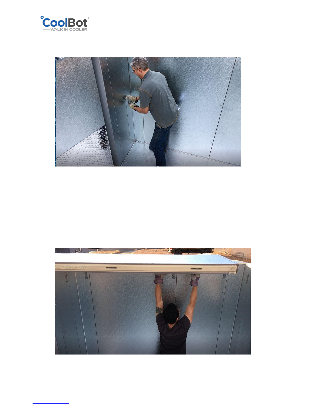
2018 © Store It Cold, LLC. Rev 2018-9a All Rights Reserved.
9. Close the wall enclosure by installing the last wall panel and give a last check around
your box to make sure all surfaces are flush and the top edges of the walls are all level.
10. Select the first ceiling panel from your Set-up drawing and place it on the corresponding
side of the cooler indicated in the drawing. Ensure that it sits properly on all the tongue
and groove edges and that it is flush with the corners and walls on the outside.
Page 13
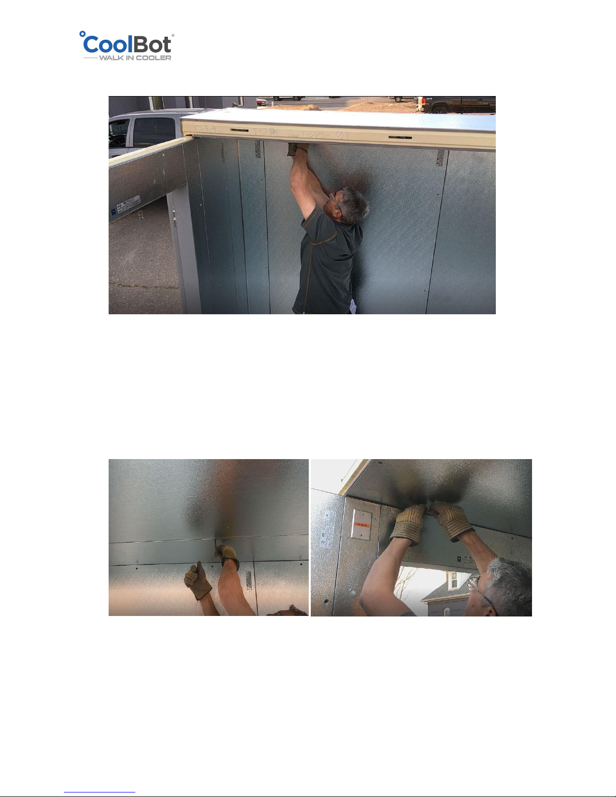
2018 © Store It Cold, LLC. Rev 2018-9a All Rights Reserved.
11. Lock the ceiling panel to the wall panels using the Hex Wrench.
12. Proceed with the next adjacent ceiling panel marked in your drawing, making sure that
it sits properly on all the tongue and groove edges and that it is flush with the corners
and walls on the outside. Lock the panel to the adjacent panel first and then lock the
panel to the walls.
Page 14
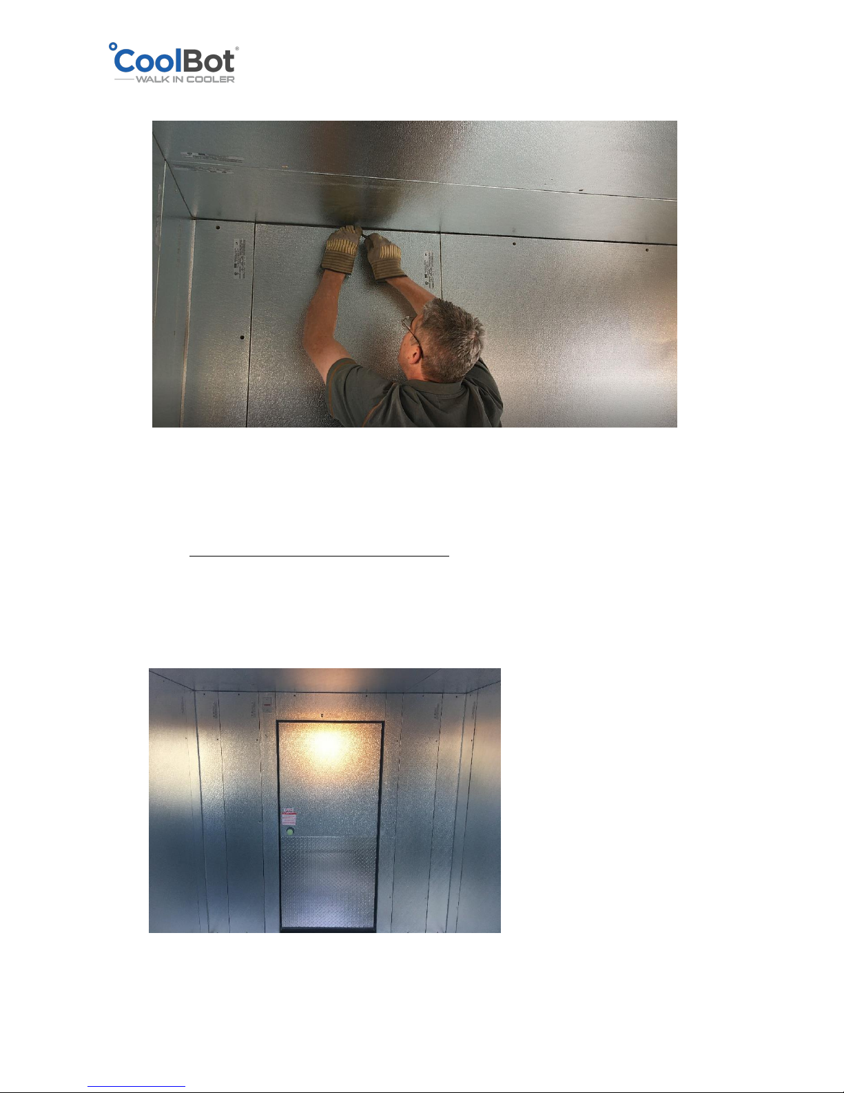
2018 © Store It Cold, LLC. Rev 2018-9a All Rights Reserved.
13. Install the last ceiling panel to close the box.
14. IMPORTANT!!
Check your box around one last time. Seams in between panels should be tight and
flush. Check your door for correct operation. Open your door less than 90° and let it
close by itself. Make sure it closes freely and makes a good seal with the frame. Ensure
the door does not hit or rub against any parts of the frame. A door that is not closing
properly is usually the result of unlevel set-up and/or improper installation. Please
unlock the necessary panels and correct positioning and leveling until the door operates
properly.
Page 15
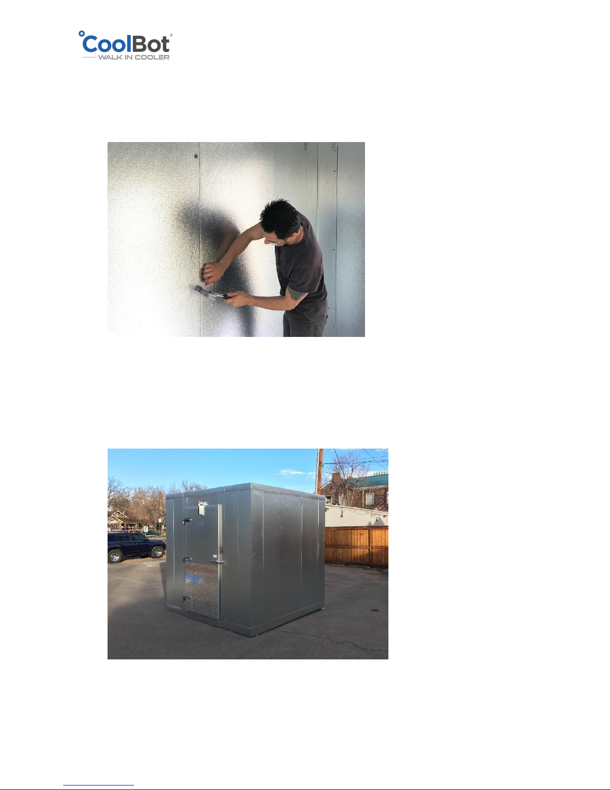
2018 © Store It Cold, LLC. Rev 2018-9a All Rights Reserved.
15. Cover wrench holes with the plastic buttons provided in the installation kit. Use a plastic
or regular hammer to gently tap them in place. If the plastic button is falling because
the hole was bored a bit bigger you can use a small amount of silicone on the back of
the button, to keep the plastic cover in place
16. Enclosure Set-up finished.
Page 16
2018 © Store It Cold, LLC. Rev 2018-9a All Rights Reserved.
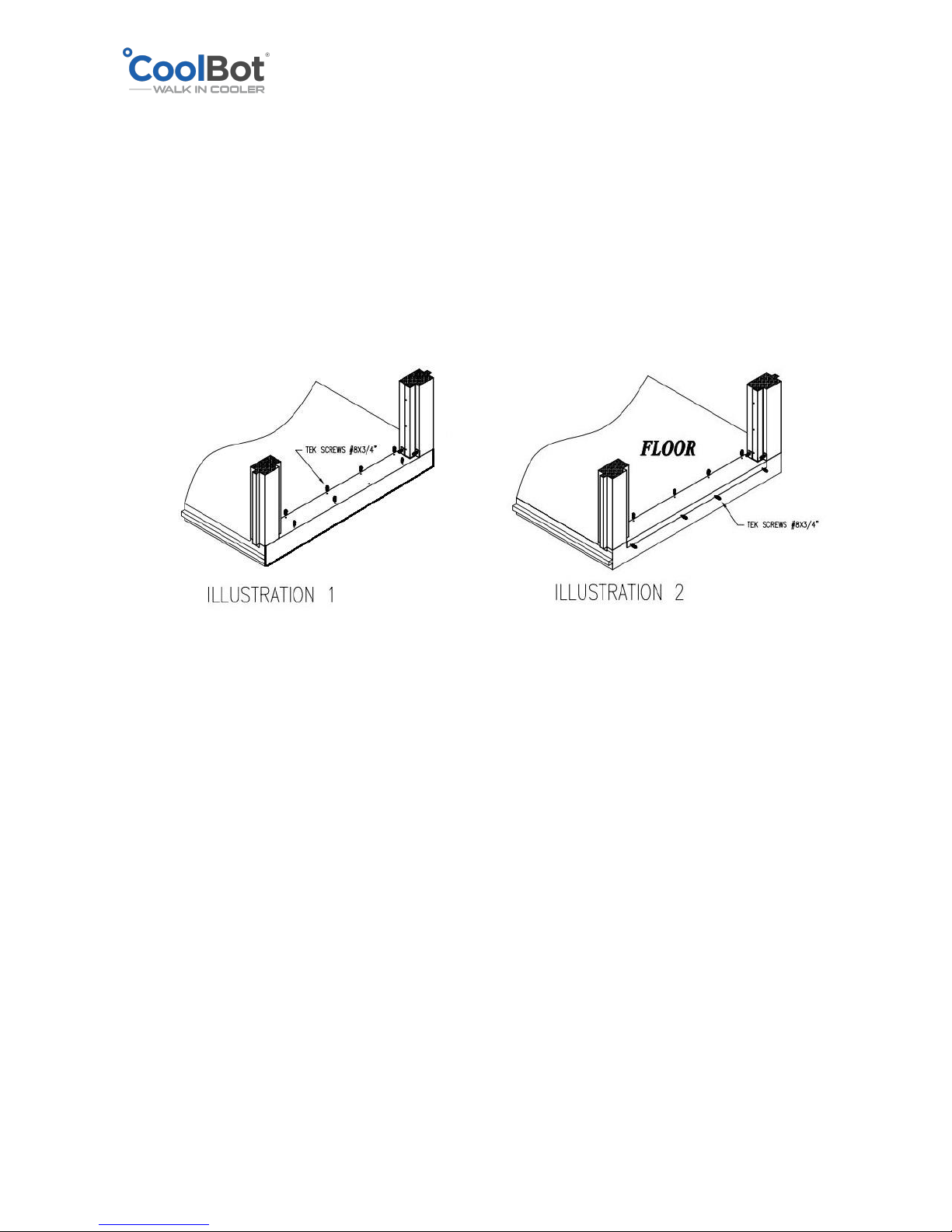
SECURING DOOR SILL PLATE (THERESHOLD) TO THE FLOOR
NOTE: Coolers with NO floor will NOT have threshold
Across the bottom of each door opening is a stainless-steel threshold.
Secure the threshold by using self-drilling screws and by screwing them into the floor panel
(illustration 1).
Some thresholds may overhang in a 90° angle to the front. Ensure you fasten that side as well
to the front side of the floor panel (illustration 2).
Page 17
2018 © Store It Cold, LLC. Rev 2018-9a All Rights Reserved.
WALK-IN COOLER INSTALLATION WITH OUT FLOOR OPTION
YOUR WALK-IN COOLER PANELS, DOOR, SCREEDING OR OUTDOOR PACKAGE PARTS MIGHT
DIFFER IN DESIGN OR LOOKS FROM THE ONES SHOWN IN THIS MANUAL.
1. Use a chalk line to mark the installation area to the dimensions of the walk-in as shown
in the drawing (Figure 1). Measure diagonally from corner to corner to be sure the floor
vinyl screed is square.
2. Apply TWO straight beads of silicone along the bottom of the vinyl screed (about an inch
away from the edges), then place the vinyl screed along the chalk lines.
NOTE: Leave the vinyl screed loose until the walk in is assembled. DO NOT anchor to the
floor.
NOTE: The vinyl screed might have to be cut as all pieces are not cut to measure from the
factory. Use a miter saw or a hand saw to cut the screeding.
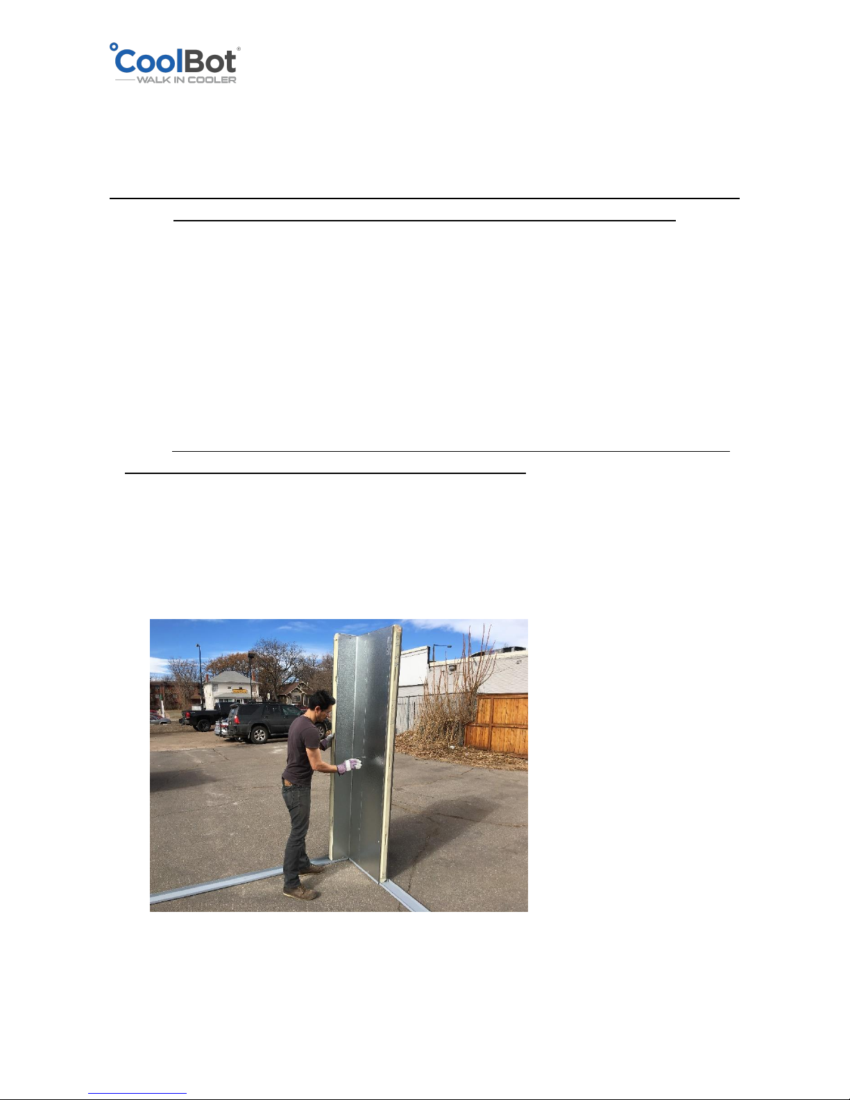
3. Begin with two corner panels. Usually the left back corner is a good place to start. Stand
the wall panels inside the screed making sure they sit correctly (fully cradled in the
screeding). Make sure that the top of each wall adjacent panel is flush with each other.
Use the wrench to secure the wall panels together to start the wall. Check for alignment
to make sure the panels are flush with each other as you proceed.
4. Select the next adjacent wall panel, going in a clockwise direction around the perimeter
and follow the same steps as above: Align, lock to the adjacent wall panel and double
Page 18
2018 © Store It Cold, LLC. Rev 2018-9a All Rights Reserved.
check for alignment making sure panel is flush on all sides and on top with the adjacent
panels.
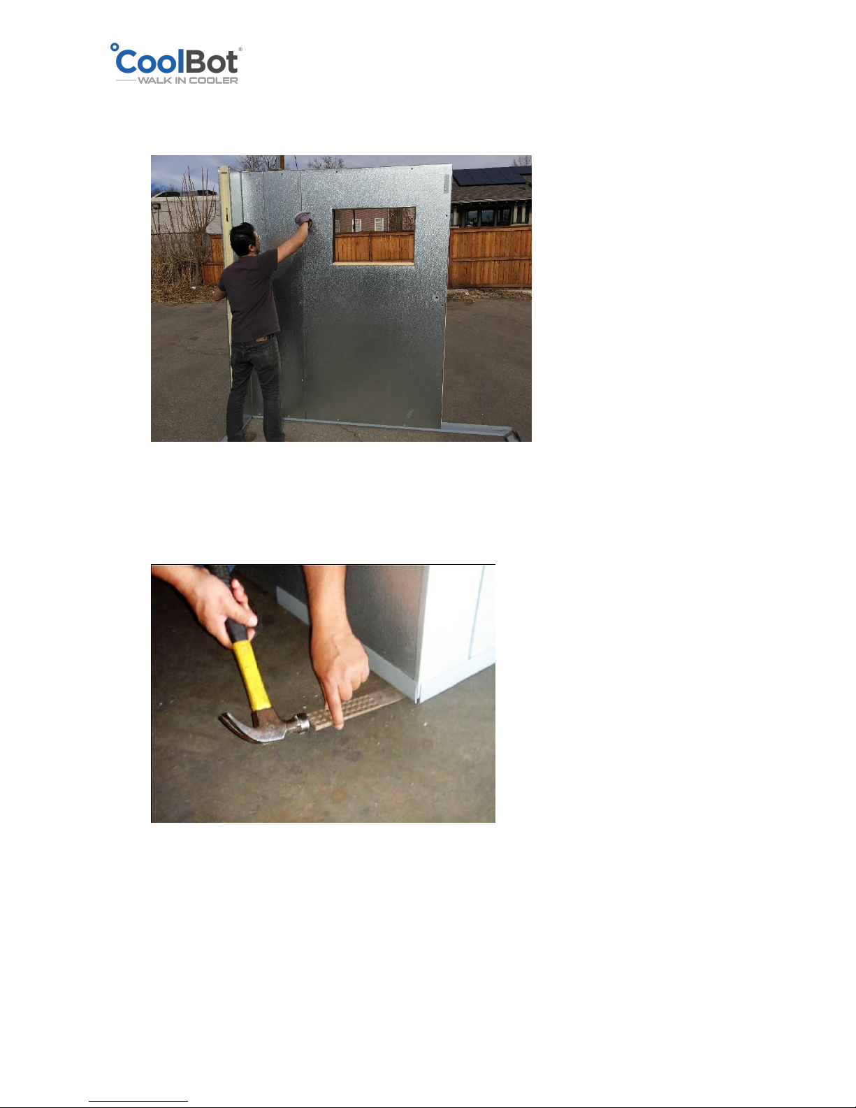
5. Install shims under vinyl screed corners and across as needed, to ensure support panel
joints and levelness of panels and walls across the top.
6. Follow the rest of the steps as mentioned in INSTALLATION OF A WALK-IN WITH FLOOR
OPTION from step 6 (inclusive) through 16.
Page 19
2018 © Store It Cold, LLC. Rev 2018-9a All Rights Reserved.
INSTALLATION OF OUTDOOR PACKAGE
(OUTDOOR UNITS ONLY)
YOUR WALK-IN COOLER PANELS, DOOR, SCREEDING OR OUTDOOR PACKAGE PARTS MIGHT
DIFFER IN DESIGN OR LOOKS FROM THE ONES SHOWN IN THIS MANUAL.
Electrical Installations should be done AFTER your outdoor membrane
has been installed.
Outdoor units that will be exposed to rain and snow have been ship with an A/C hood, a roof
membrane and a hardware kit as part of your outdoor package.
Install the A/C hood before your roof membrane.
Included items of your outdoor package:
1. A/C hood
2. Roof Membrane – pre-cut about 1 ft larger on each side
3. Aluminum Flat Bars - predrilled
4. Installation Hardware:
a. Flat Bar Anchors (S/S or hex metal screws)
b. Truss-Plate Anchors (black long screws)
5. Truss Plates (only to be used in coolers with a side equal or greater than 10 ft)
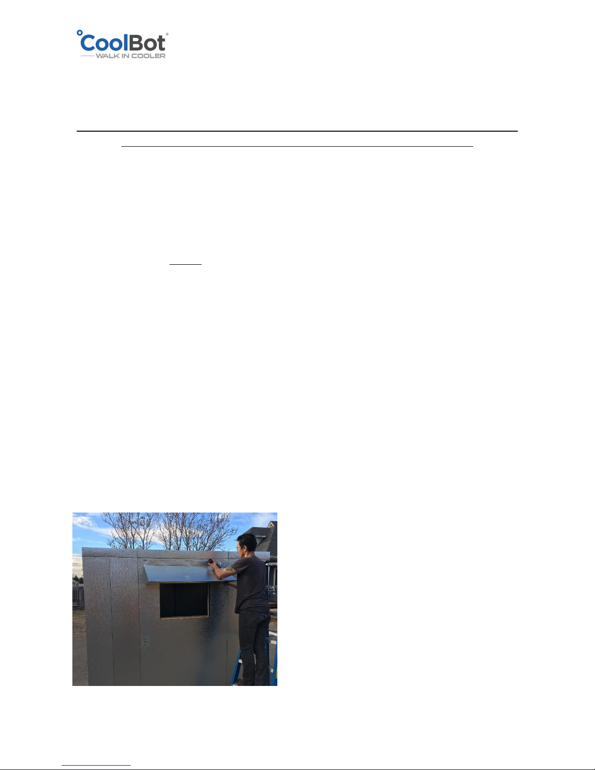
RAIN HOOD (OUTDOOR UNITS ONLY)
Align the top edge of the hood no more than 2” below the horizontal joint in between the
ceiling panel and the wall panel. Make sure it’s center in position with respect to the A/C
opening. Screw in place with the self-drilling metal screws.
Page 20
2018 © Store It Cold, LLC. Rev 2018-9a All Rights Reserved.
ROOF MEMBRANE (OUTDOOR UNITS ONLY)
IMPORTANT
Improper installation may result in water accumulation or water infiltration through the
membrane. SIC recommends the roof membrane to be installed by a contractor to ensure it is
installed correctly.
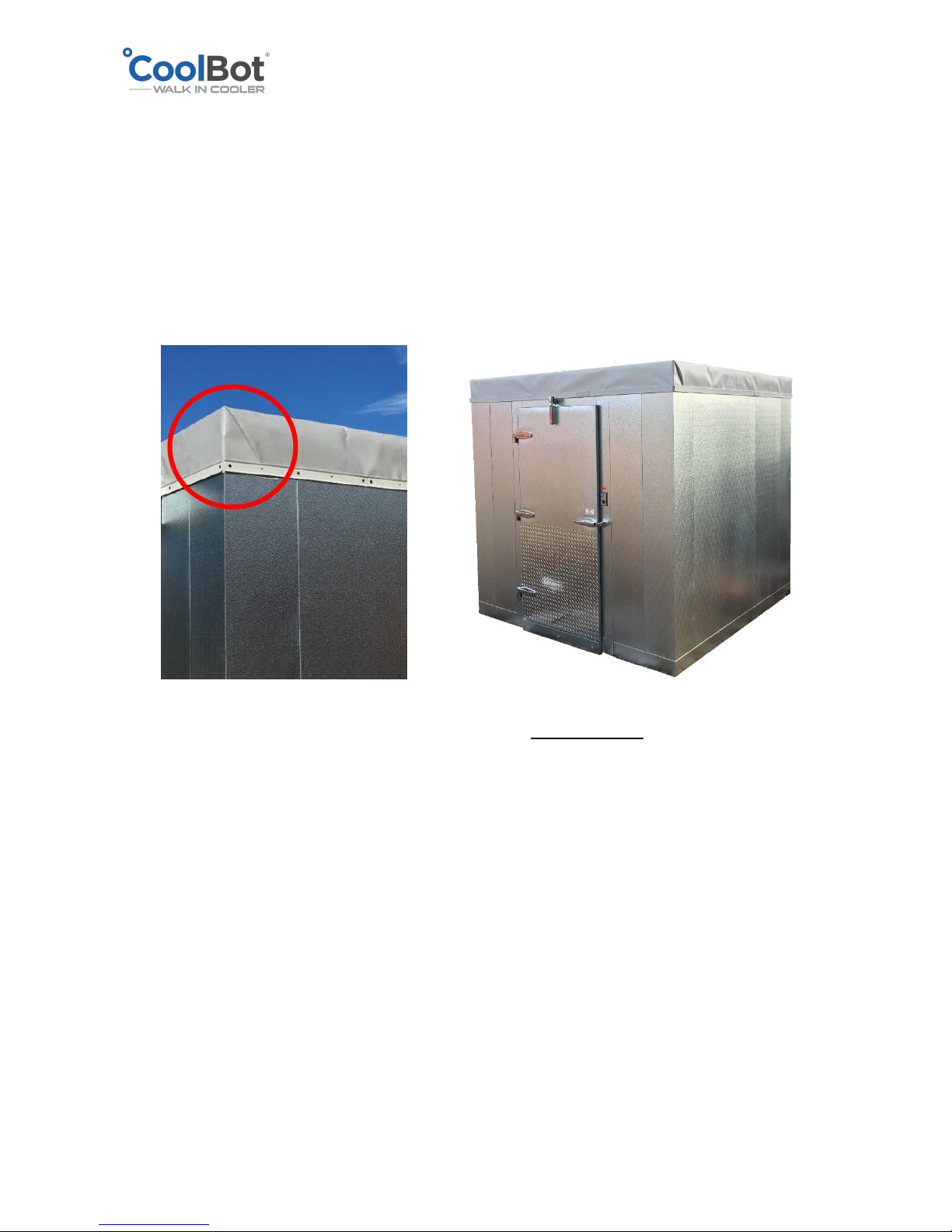
MEMBRANE INSTALLATION ON SMALL COOLERS - ALL SIDES ARE LESS THAN 10FT
1. Extend your membrane on the roof of your walk-in with the soft smooth semi-glossy
textured side UP (overlapping seams DOWN). Ensure that it hangs approximately the
same amount on all sides. Don’t worry if it is too long, it can be trimmed after it’s
installed in place.
2. Starting at the front of the cooler, pull down on the membrane and secure to the wall by
installing the metal trimming provided. Screw the metal trimming to the front side using
the self-drilling hex sheet metal screws provided in your installation kit.
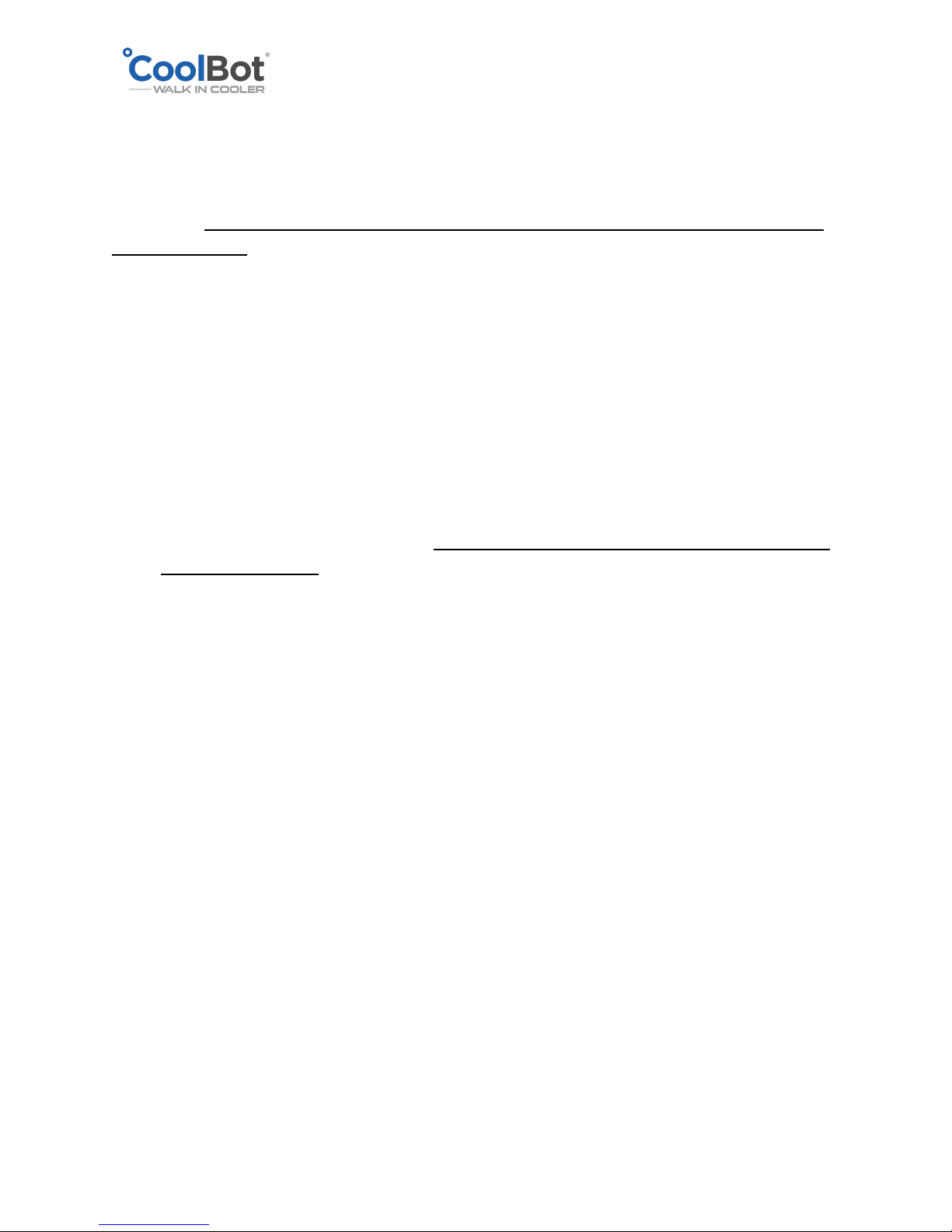
IMPORTANT! Make sure the trim is level and below the seam in between the wall panel
and the ceiling panel. It’s important that this seam stays under the membrane.
3. Repeat the same process for the back side of the cooler.
4. After the front and back part of the membrane have been secured, proceed to one of the
sides of the cooler. Tuck the excess fabric at the front corner underneath the membrane
to create a nice fold. Pull down tight and start securing the membrane to the wall panels
following the same recommendations as before. Install the trimming at the same level as
you did on the front and back to remain constant around the perimeter of the cooler.
Work your way from front to back as you pull down tight and secure.
Page 21
2018 © Store It Cold, LLC. Rev 2018-9a All Rights Reserved.
5. After the membrane has been correctly installed and secured to the sides of your cooler,
you can trim with a utility knife the excess fabric below the trim if desired. This will give a
cleaner and more professional look but it is not necessary.
6. Caulk with silicone the top edge of the trimming bars for added protection.
7. Your cooler is now set up for outdoor use.
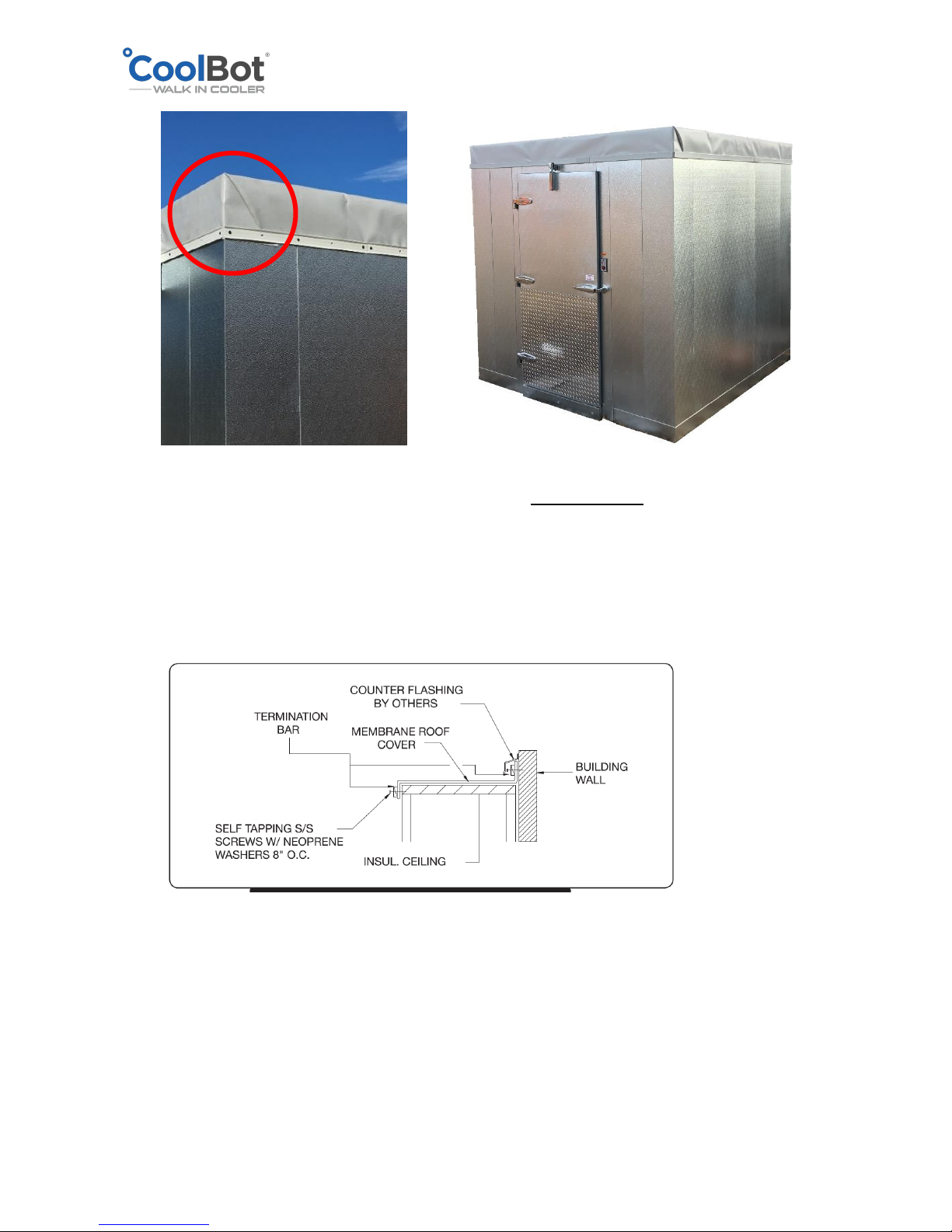
MEMBRANE INSTALLATION IF YOUR COOLER IS 2” FROM A WALL
MEMBRANE INSTALLATION ON LARGE COOLERS - ONE SIDE MEASURING 10FT OR MORE
1. Extend your membrane on the roof of your walk-in with the soft smooth semi-glossy
textured side UP (overlapping seams DOWN). Ensure that it hangs approximately the
same amount on all sides. Don’t worry if it is too long, it can be trimmed after it’s
installed in place.
Page 22
2018 © Store It Cold, LLC. Rev 2018-9a All Rights Reserved.
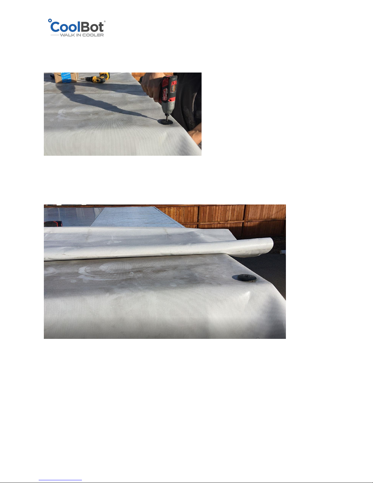
2. Proceed to install your first anchor (TRUSS PLATE) at one of the corners of a short side of
the Cooler ceiling to keep the membrane in place. Use the black long screws provided.
3. Roll back the membrane from the other end to about half way or more. This will allow
for easy pulling on the membrane to make it taut when securing to the ceiling with the
anchors (TRUSS PLATES).
4. Making sure that the membrane is taut and straight, install your second anchor (TRUSS
PLATE) in the middle of the ceiling in line with the first anchor. Secure a third one on the
other end to finish the first row.
Page 23
2018 © Store It Cold, LLC. Rev 2018-9a All Rights Reserved.
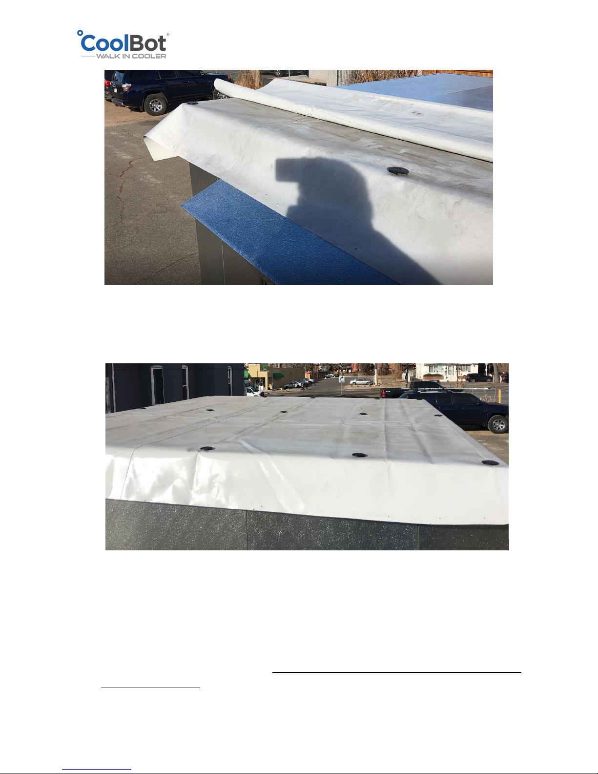
5. Continue the same way installing horizontal rows of 3 anchors around every 24 inches as
you unroll and pull tight on the membrane each time you are screwing a new row of
anchors.
8. Starting at the front of the cooler, pull down on the membrane and secure to the wall by
installing the metal trimming provided. Screw the metal trimming to the front side using
the self-drilling hex sheet metal screws provided in your installation kit.
IMPORTANT! Make sure the trim is level and below the seam in between the wall panel
and the ceiling panel. It’s important that this seam stays under the membrane.
Page 24
2018 © Store It Cold, LLC. Rev 2018-9a All Rights Reserved.
9. Repeat the same process for the back side of the cooler.
10. After the front and back part of the membrane have been secured, proceed to one of the
sides of the cooler. Tuck the excess fabric at the front corner underneath the membrane
to create a nice fold. Pull down tight and start securing the membrane to the wall panels
following the same recommendations as before. Install the trimming at the same level as
you did on the front and back to remain constant around the perimeter of the cooler.
Work your way from front to back as you pull down tight and secure.
11. After the membrane has been correctly installed and secured to the sides of your cooler,
you can trim with a utility knife the excess fabric below the trim if desired. This will give a
cleaner and more professional look but it is not necessary.
12. Caulk with silicone the top edge of the trimming bars for added protection.
13. Caulk all the TRUSS PLATES around and add a little dab in the middle where the screw is
for added protection.
14. Your cooler is now set up for outdoor use.
Page 25
2018 © Store It Cold, LLC. Rev 2018-9a All Rights Reserved.
A/C INSTALLATION INTRUCTIONS
This is a quick, simple guide to install your LG unit in your Cooler enclosure.
Please read the OWNER’S MANUAL supplied with your A/C unit to familiarize yourself with the
PROPER operation, maintenance, usage, and installation of your A/C unit.
1. Carefully unpack your A/C unit out of the box. Make sure the unit remains in the correct
position. DO NOT stand the box or the A/C unit on the side, back or front. DO NOT
discard any of the contents inside the box.
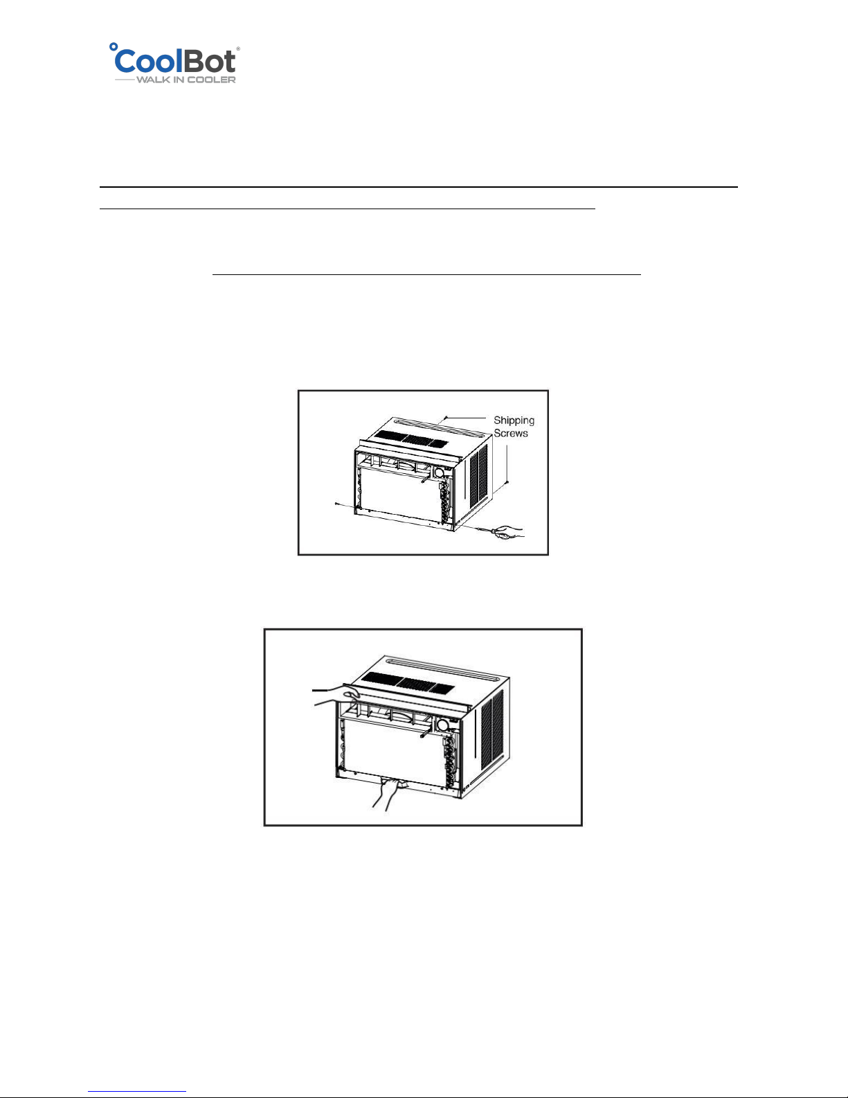
2. Once your unit is out of the box, remove the 4 screws which fasten the cabinet at both
sides and back.
3. Slide the unit from the cabinet by gripping the base pan handle and pulling forward
while bracing the cabinet.
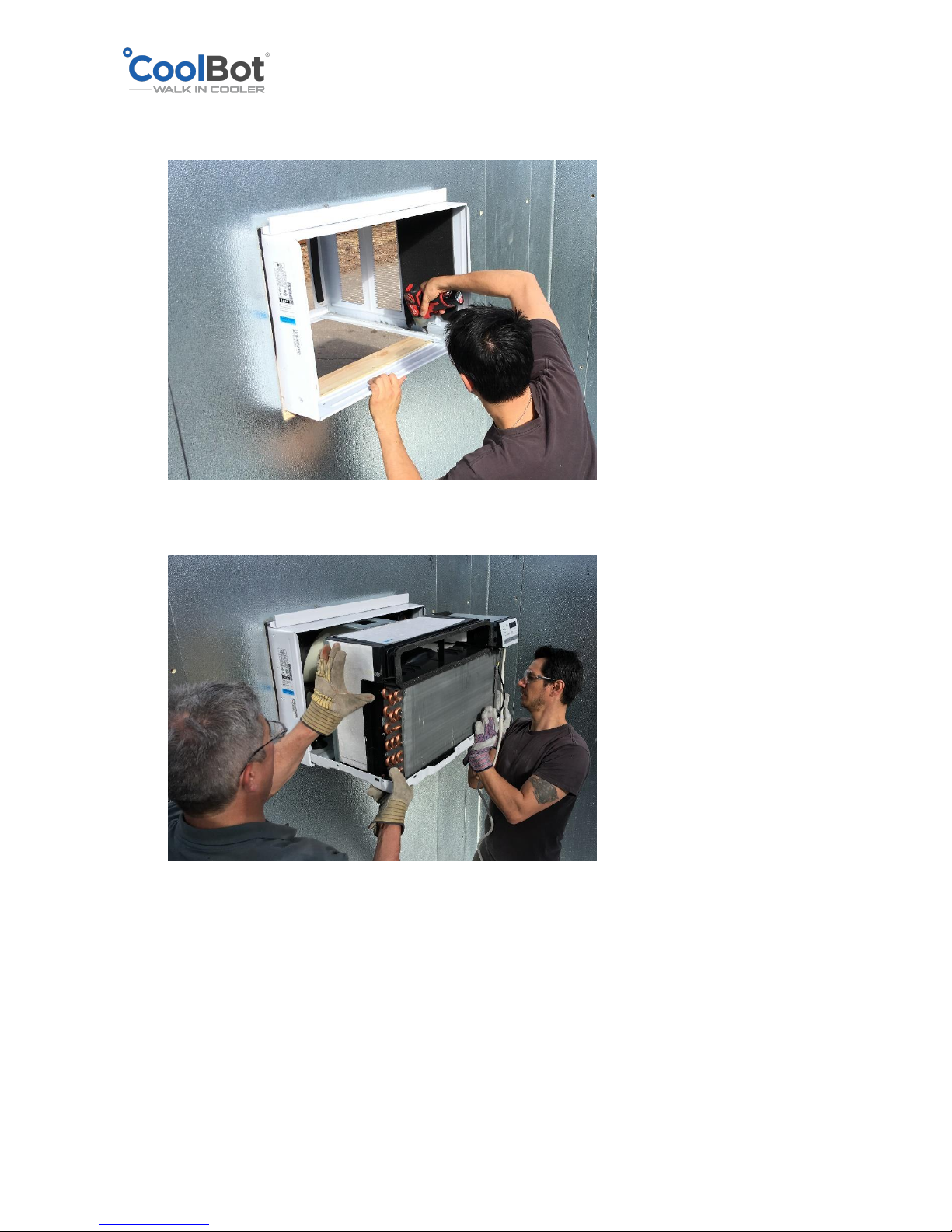
4. Carefully insert the A/C cabinet on the pre-cut hole from the inside of the cooler and
slide towards the outside until the top bracket of the cabinet touches the wall panel.
5. Ensure that the cabinet has a slight tilt downward towards the outside. Position the
cabinet so that the back is about ½” to 1” lower than the front. Use the holes at the
Page 26
2018 © Store It Cold, LLC. Rev 2018-9a All Rights Reserved.
bottom of your A/C cabinet to screw in place to the edge of the precut hole on the wall
panel.
6. Slide the unit inside the cabinet.
7. Do not install the front cover of the A/C at this point.
8. You can use the foam strips provided with your A/C unit to fill the gaps on the wall in
between the A/C opening and the cabinet.
A great alternative is to use refrigeration pipe insulation available at hardware stores
(looks like a pool noodle but black) and cut in strips. Insert the strips into the gaps to
seal the space.
Page 27
2018 © Store It Cold, LLC. Rev 2018-9a All Rights Reserved.
Electrical Installations should be done AFTER your outdoor membrane
has been installed (outdoor units ONLY).
ELECTRICAL INSTALLATION
IMPORTANT!!
The enclosure does not have any predrilled access holes or electrical hookups from the
factory. Electrical installation for your cooler SHOULD be performed by a qualified electrician
to ensure correct power supply, wiring, and compliance with local codes.
Required Connections
Cooler
Door
CoolBot
A/C
6 x 6
120V
120V
120V
8 x 8
120V
120V
120V
8 x 12
120V
120V
230V
10 x 14
120V
120V
230V
Page 28
2018 © Store It Cold, LLC. Rev 2018-9a All Rights Reserved.
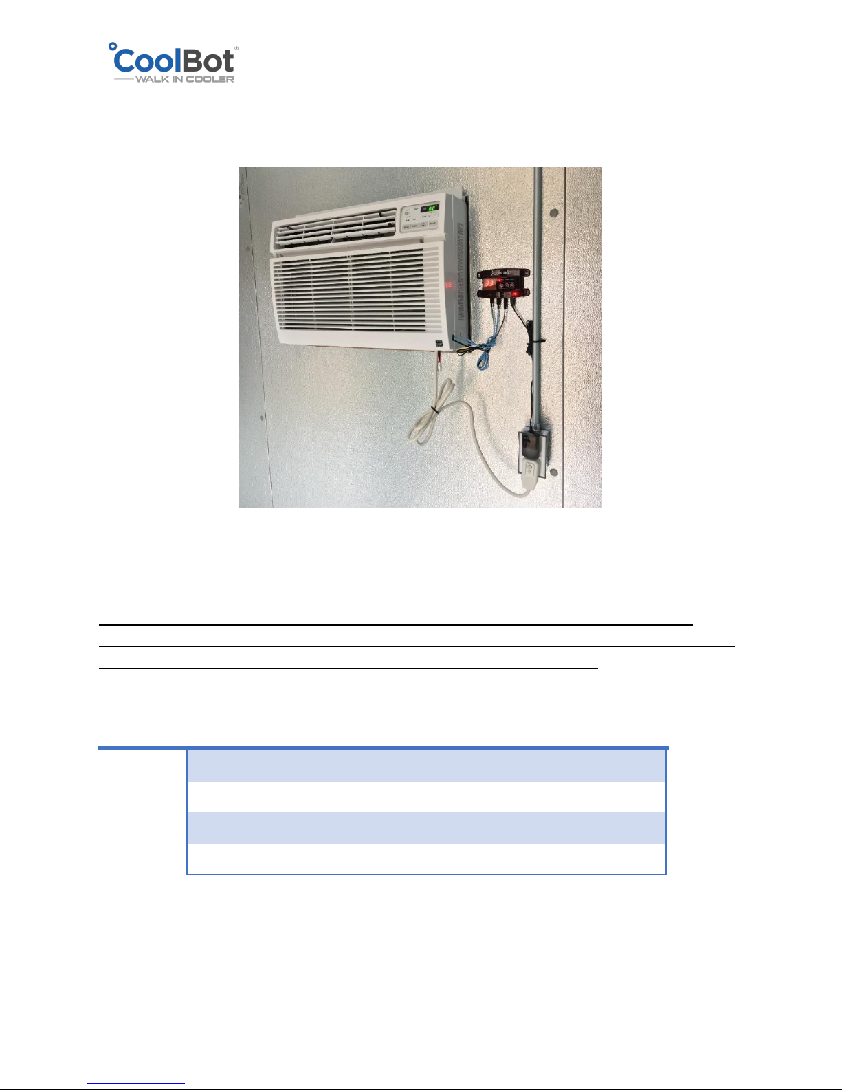
• A 120V 60Hz single phase power connection on the front is required to supply power to
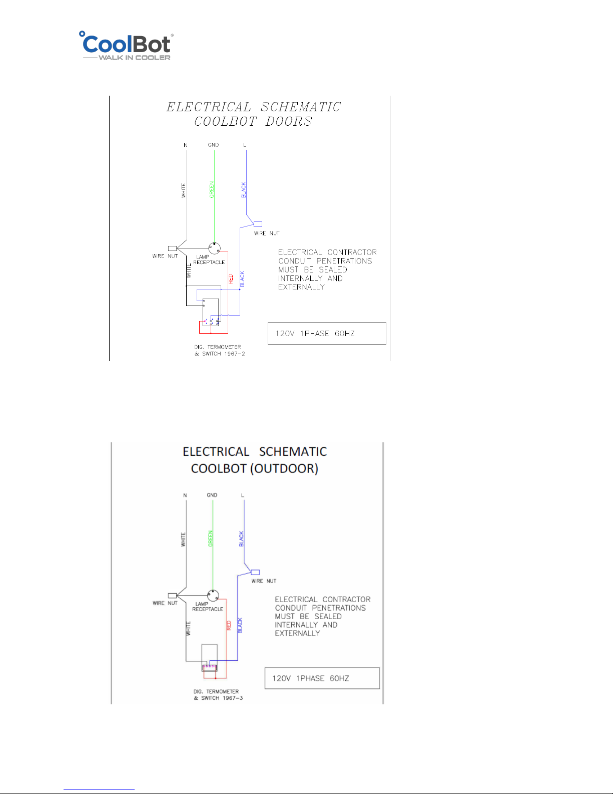
the light and the digital thermometer on all cooler sizes. Please, ask your Electrician to
refer to the wiring diagrams below to wire the Cooler Light and Thermometer.
• A 115V 60Hz single phase power connection is required on the back (or sides) to supply
power to the A/C unit shipped with your Cooler (15KBTU or below ONLY)
• A 230V 60Hz single phase connection is required on the back (or sides) to supply power
to the A/C unit shipped with your Cooler (18K or 24K BTU ONLY).
• A 115V 50-60Hz single phase connection is required on the back (or sides) to supply
power to the CoolBot Digital controller.
LIGHT SWITCH AND LIGHT FIXTURE
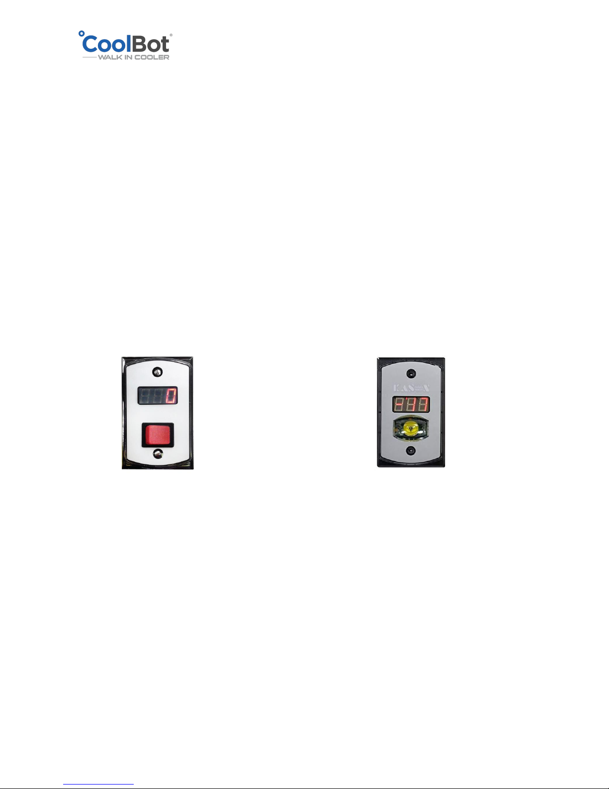
Your Cooler may have one of these two types of switches:
Kason 1967-2 Kason 1967-3
(INDOOR Cooler ONLY) (INDOOR or OUTDOOR Cooler)
OPERATION:
• Turn on / off switch: Depress red rocker switch (1967-2) or touch yellow button (1967-3)
• Depending on temperature of room will read:
▪ FrE or F1 / F2 [-40°F to 30°F] or [-40°C to -1°C]
▪ CoL or C1 / C2 [32°F to 50°F] or [0°C to 10°C]
▪ Hot or H1/ H2 [ 75 -104°F] or [24°C to 40°C]
• Temperature Units: Default °F, install small black jumper on the back of controller for °C
• Errors / Warnings:
▪ Low battery (if connected): "B" on display will blink (replace battery)
▪ "Hot / H1 / H2" room temperature is above 75°F
▪ "OFF" temperature probe is not connected (install, re-check connection, or replace
temp probe on the back of the controller)
Page 29
2018 © Store It Cold, LLC. Rev 2018-9a All Rights Reserved.
ELECTRICAL WIRING FOR 1967-2
ELECTRICAL WIRING FOR 1967-3
Page 30

2018 © Store It Cold, LLC. Rev 2018-9a All Rights Reserved.
OPERATION AND MAINTENACE INSTRUCTIONS
1. OPERATION
• Product inside your walk-in cooler should not be overloaded or tightly stacked as to
inhibit proper air flow and air distribution throughout the box.
• DO NOT STACK PRODUCT INFRONT OF THE A/C.
The top of the box is not designed for storage. Items stored on top may cause
condensation, damage panels and void the warranty.
2. ROUTINE CLEANING
• Wipe panels with a damp cloth using mild soap. DO NOT use harsh chemicals or
abrasive pads or cleaners. Stainless should be cleaned with stainless steel cleaner;
wipe in the direction of the grain. Dry all finishes thoroughly.
• Clean door gaskets using mild soap; wipe dry after cleaning
• Do not wash down or spray the inside of the walk-in with water
• Clean the fins of your A/C following the instructions on page 15 ( DIRTY FINS ) of
your COOLBOT INSTRUCTIONS MANUAL AND TROUBLESHOOTING GUIDE.
3. PERIODIC INSPECTIONS
• Inspect the door gasket for wear and make sure it seals tight against the Stainless-
Steel trim of the frame. Replace gaskets if worn or torn.
• Inspect the hydraulic door closer to ensure that it engages when the door is within
an inch or two and pulls the door tight.
• Inspect the door hinges and lubricate hinge pins with petroleum jelly as needed.
• Inspect the door sweep gasket at the bottom of the door for proper seal. Replace if
sweep is worn or torn.
• Check the Thermometer reading with another thermometer in the same location or
by placing the thermometer probe in to a cup of water with ice; it should read 32°F
(0°C).
• Check for missing plugs and buttons and replace as necessary.
 Loading...