

Cool-A-Zone C400, C300, C200 User Manual
User Manual
C400, C300, C200
9052 Long Point • Houston, TX 77055 • 888.827.1675 • info@coolazone.com
www.coolazone.com

Transportation Page 3
Installation & Set-Up Page 4
Operating Procedures Page 5-8
Storage Page 8
Care & Cleaning Page 9
Safety Page 10
Parts Page 11
Specications Page 12
Applications Page 13
CE Certicate Page 14
Contact Information Page 15
Product Registration Page 16
Table of Contents
Transportation .........................................
Installation & Set-Up ...............................
Operating Procedures .............................
Storage .......................................................
Care & Cleaning .......................................
Safety ........................................................
Parts ............................................................
Specications ..........................................
Applications ..............................................
CE Certicate ............................................
Contact Information ...............................
Product Registration ...............................
2
www.coolazone.com

Transportation
TRANSPORTATION:
When the fan is being transported, avoid any impact or collision, or applying excessive
weight to the unit. Excessive weight could damage the unit under these circumstances.
3
www.coolazone.com
Moving State
Fixed State
Unlocked Caster Locked Caster
4
www.coolazone.com
Installation & Set-Up
INSTALLATION:
If the fan is placed close to a wall or other obstacle, keep a distance of 3 feet between the
wall or obstacle and the face of the cooling pads.
When placing the fan, take the following into consideration:
a. Uninterrupted fresh air should be made available to the cooling pad side of the unit.
Please do not use the fan in a closed area.
b. Avoid blocking the air output (front) side of the fan. Cool air released from the unit
should be able to freely circulate within an open area.
c. In order to prevent air from being re-circulated, ensure that the area to be cooled is
properly ventilated.
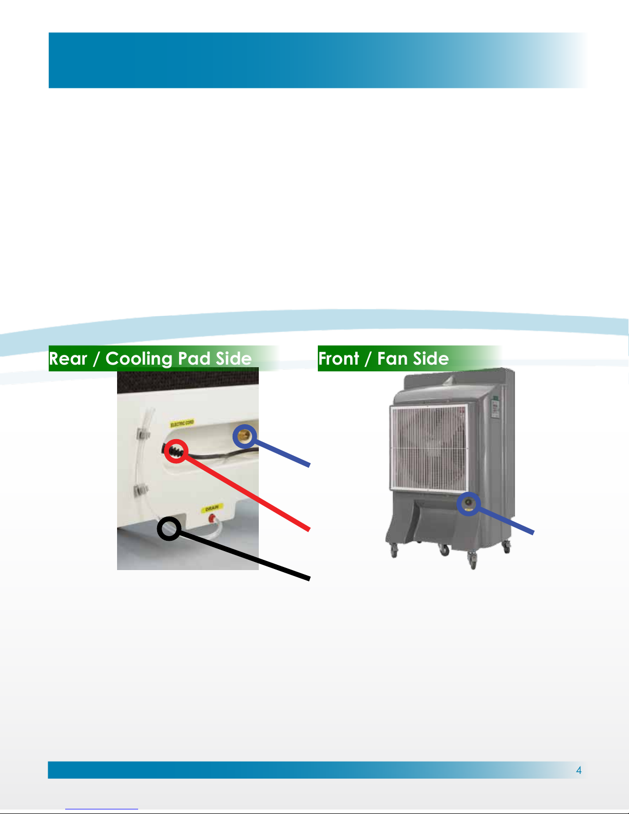
If you have placed the unit at a location where it is inconvenient to connect the water inlet
to a water source, you may pour clean water into the back of the unit.
A full sump tank supply the necessary water for about 3 hours.
Water Valve
Drain Line
Water Inlet
Electric Cord
Rear / Cooling Pad Side
Front / Fan Side
5
www.coolazone.com
Operating Procedures
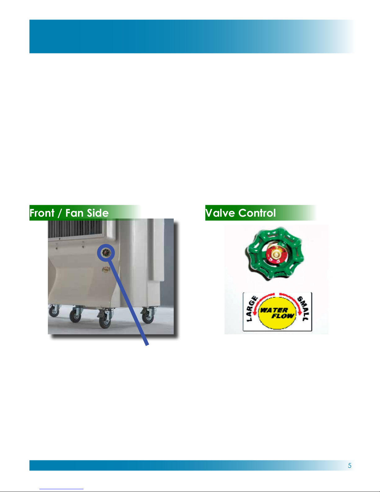
ADJUSTMENT OF THE WATER FLOW & USER’S POSITION:
When the water ow rst starts, ensure that the spray bar, located above the cooling pads,
is evenly distributing water over the pads at a slow drip. Use the “SPRAY BAR ADJUSTMENT”
valve on the front of the unit to make any water ow adjustments.
When proper adjustments are made, a slow drip should be enough water to keep the pads
soaked. Note that excessive water ow can reduce efciency in air cooling. With proper
adjustment, cooling capacity will be increased.
New pads in the unit require a ‘breaking-in’ period for up to one week, before optimal
efciency can be achieved.
Front / Fan Side
Water Valve
“SPRAY BAR ADJUSTMENT”
Valve Control
Counter Clockwise:
Increases Water Flow
Clockwise:
Decreases Water Flow
6
www.coolazone.com
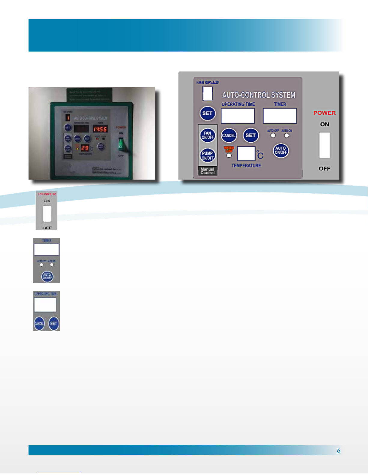
Operating Procedures
Power (Emergency Stop)
To ensure that the fan is functioning normally, rst turn on the power switch. The unit
should make a short beeping sound, and all lights on the control panel should ash
once. “Temperature Display” is now ready for use.
Auto Control
Automatic Start: Push the “AUTO ON/OFF” button. Water pump starts when “AUTO ON
” lights up. A timer counts down from 30 seconds while the pump sprinkles water over
the cooling pads, after 30 seconds the fan automatically starts.
Operation Timer
Each short push on the “SET TIMER” button programs 5 minutes of operating time. Press
the “SET TIMER” button for 3 seconds to program 1 hour of operating time.
After the set operating time has expired, the unit goes into auto shut-down mode
whereby the water pump shuts down, a 15 minute timer is activated, and the fan
continues to blow to dry the cooling pads. When the 15 minute timer is complete, the
unit powers down.
For example, if 4 hours of operating time is required, only 3 hours and 45 minutes is
needed when setting the timer. After the operating timer has expired, the unit will
activate the automatic shut off system.
Automatic Shut Off System
Press the “AUTO ON/OFF” button to manually turn off the fan. When pressed, the unit
will activate the automatic shut-off system whereby the water pump shuts down,
“AUTO OFF ” lights up, a 15 minute timer is activated and the fan continues to blow to
dry the cooling pads. When the 15 minute timer is complete, the unit powers down.
THE AUTO CONTROL SYSTEM:
 Loading...