

Page 1
FARM PRODUCTS DIVISION
AMERICAN COOLAIR CORPORATION
PHONE (904) 389-3646 FAX (904) 387-3449
MEMBER OF AMCA
P.O. BOX 2300
JACKSONVILLE, FLORIDA 32203
E-MAIL - [email protected]
MNEFDD52, MNBCDD52, and MNCFDD52
GALVANIZED WALL FANS
Installation, Operation, and Maintenance Instructions
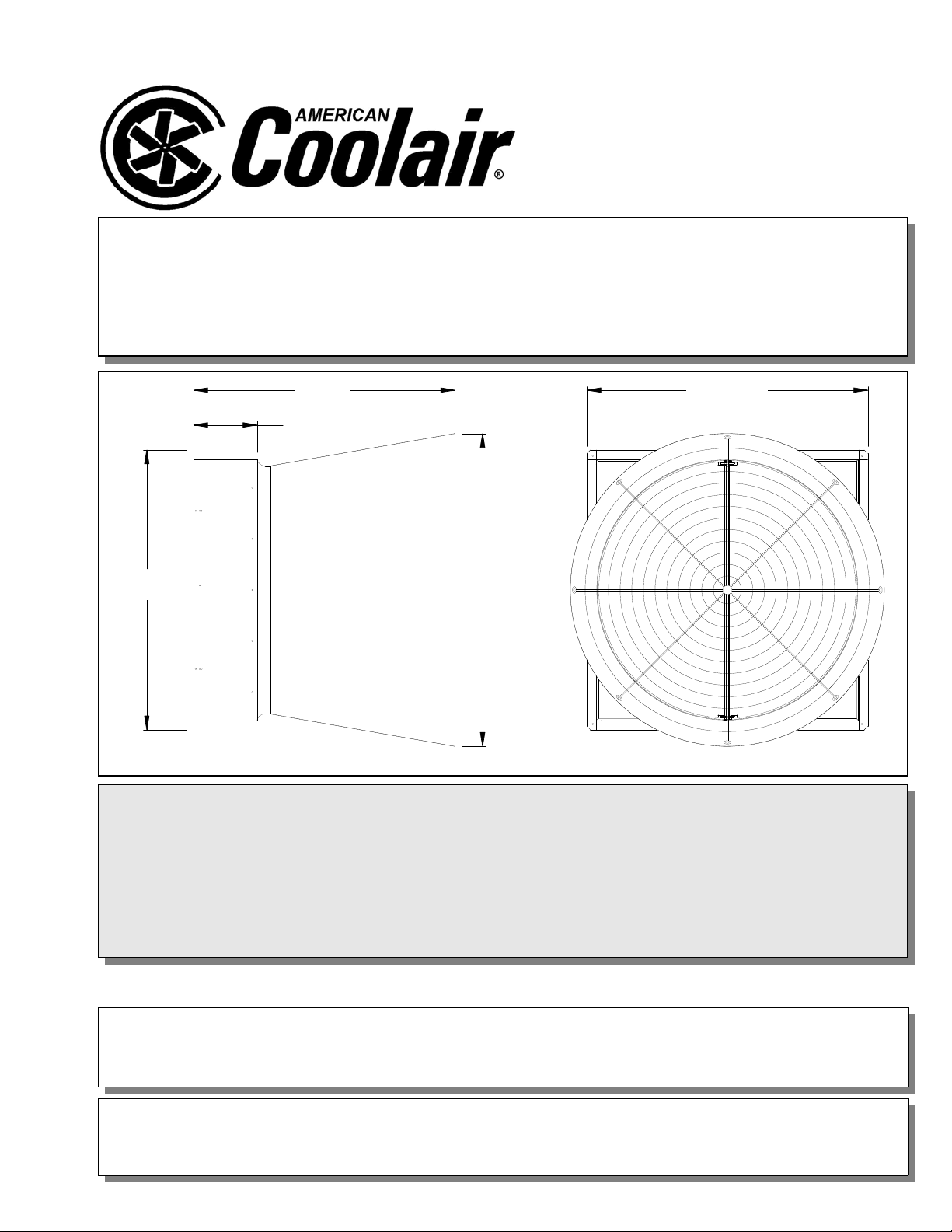
58 15/16
58 15/16
Figure 1
55 1/2
14 3/8
67 3/8
MNEFDD52LE * MNEFDD52L * MNEFDD52M
MNBCDD52LE * MNBCDD52L * MNBCDD52M
MNCFDD52LE * MNCFDD52L * MNCFDD52ME
MNCFDD52M
UNPACKING
Inspect the fan for signs of shipping damage. It is the responsibility of the customer to report any
shipping damage to the freight carrier.
WHAT SHOULD YOU FIND?
Fan, (4) Housing Sheets, Damper Door Assembly, Cone (4 cone panels and 4 cone gussets), Rear Housing Guard,
Front Cone Guard, and Hardware Package
Page 2
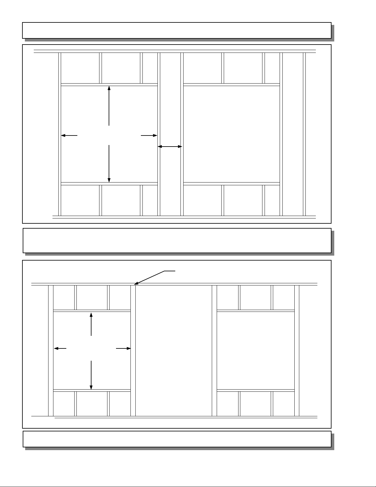
56 3/4” SQ. I.D.
FRAMING
Spacing
Figure 2
FRAME CONSTRUCTION
RECOMMENDED SPACING IS 12”
4” x 4” Post
56 3/4” SQ. I.D.
Figure 3
PAGE 2
POST CONSTRUCTION
Page 3
FAN HOUSING ASSEMBLY & INSTALLATION
The housing consists of 4 housing sheets that must be fastened together. The top and side
sheets are identical. The bottom sheet has two 1-inch diameter drain holes. Assembly
should be done inside the building in which it will be placed. To assemble the housing, plac e
one sheet so that the flange on the long side of the sheet is down. Then take another sheet
and place it at 90° to the first so that its flat short end is overlapped by the flanged short end
of the first sheet. The three inside holes, as well as the hole in the corner at the intersection
of the two flanges, should overlap. Using three 1/4” x 3/4” bolts and three 1/4” whiz-lock nuts,
fasten the two sheets at the overlapping holes on the inside corner of the two sheets. Push
the bolts from the outside in, and thread the nuts on the inside. This process should be
repeated for the two remaining sheets. After the fourth sheet has been fastened to the third,
it should also be fastened to the first, completing the housing.
Next, lift the housing into place in the wall opening. Using the 4 overlapping corner holes and
the 3 individual holes in each sheet flange, fasten the housing to the building frame (hardware
not provided).
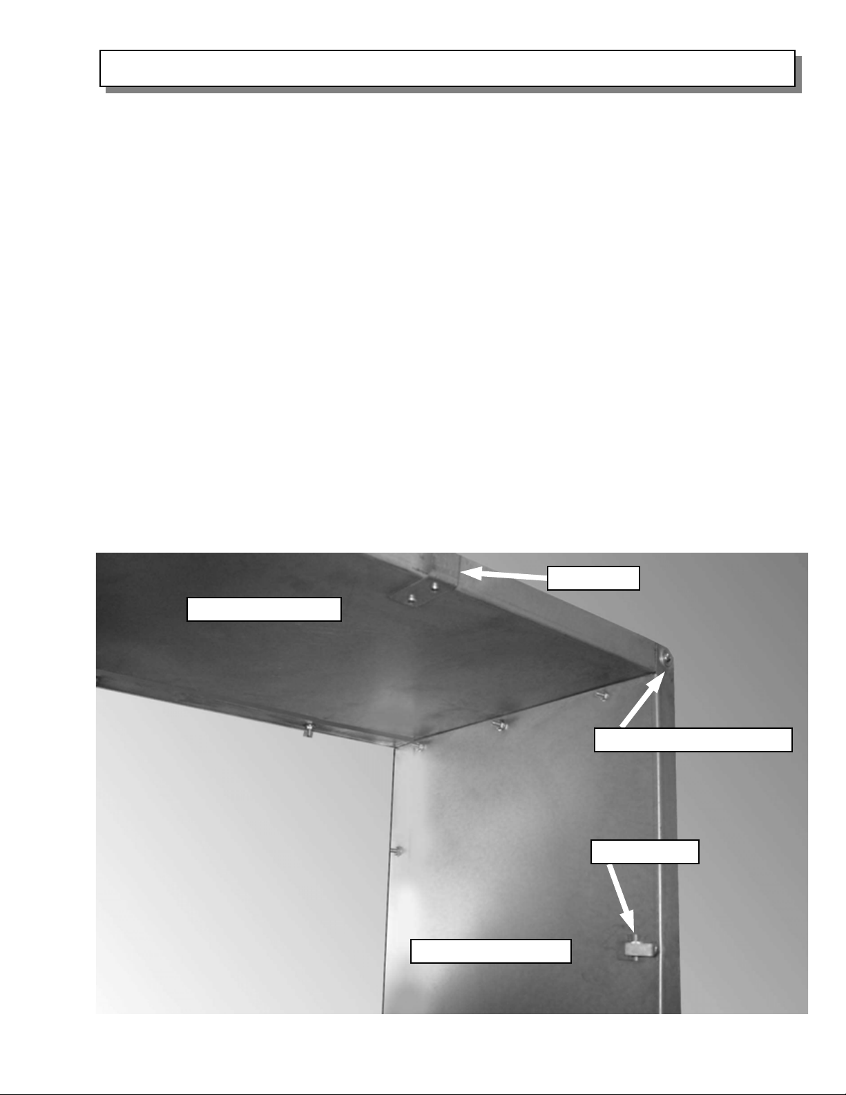
After securing the housing to the frame, attach the 2 guard latches each to the side and
bottom housing sheets as shown in Figure 4 using the #10 screws provided. The screws
should go through the latch, through the housing, and into the building frame. In the same
manner, attach the two guard clips to the top housing sheet using #10 wood screws as shown
in Figure 4.
Install flashing around the housing and caulk to properly seal fan to wall.
Top Housing Sheet
Guard Clip
Overlapping Corner Hole
Guard Latch
Side Housing Sheet
Figure 4
PAGE 3
Page 4
F A N A SSEMBLY AND MOUNTING
Before installation of fan, check carefully for shipping damage which may result in blade
misalignment, deformed parts or other damage. After motor has been mounted, check pulley
alignment and belt tension. (For details on pulley alignment, refer to Page 8 in this booklet.).
Before connecting the power source, check motor nameplate to be sure the correct phase and
voltage will be applied. Single phase motors are shipped from factory wired for 230 volt
operation. For low voltage operation see motor manufacturer’s instructions on nameplate.
Make sure propeller turns freely without striking fan frame or any foreign object which may
interfere with its operation. Note direction arrow on orifice to make sure propeller is rotating in
the correct direction when power is applied.
Motor Mounting
If the fan and housing are factory assembled, then the motor bracket is already mounted in the
correct holes. If the fan is not factory mounted to the housing, the motor bracket will need to be
moved from it’s shipping position.
1. A) For Models MNBRDD52 and MNBCDD52:
If needed, remove the motor bracket from its shipping position and bolt it to the uprights
using the 3rd and 4th holes from the bottom of the uprights. Note: It may be necessary to
slightly adjust the motor bracket in it’s slots to achieve proper belt tension.
B) For Model MNCFDD52:
Refer to Form #220-41 (and #401-168 if an Auto Belt Tension er is being used) for motor
mounting instructions.
2. Place the motor on the motor bracket and bolt it down using the hardware provided.
Make sure the motor base remains level.
3. The motor pulley should be placed on the motor shaft with the “set screw” side of the
pulley toward the motor. Using a long straight bar, check the alignment of the motor
pulley and the fan hub pulley. If necessary, loosen the motor pulley set-screw and/or the
motor mounting bolts and adjust as necessary. Re-tighten pulley set screw and motor
mounting bolts. IMPORTANT: Motor bracket bolts must be secured to maintain proper
belt alignment and tension.
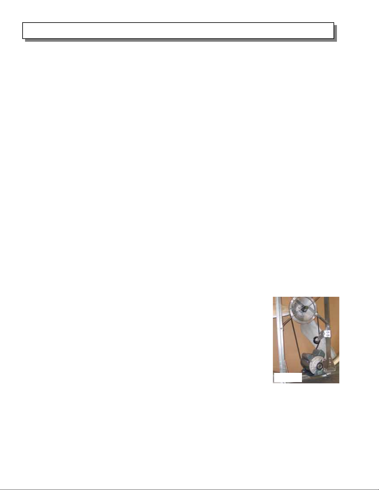
Once the motor has been properly mounted and the pulleys have been
aligned, complete the assembly of the fan by threading the belt over the fan
hub pulley groove, motor pulley, and belt tensioner (if included) as shown in
Figure 5. For Models MNBRDD52 and MNBCDD52, the tensioner is
assembled and should be set for proper belt tension. If a tension
adjustment becomes necessary, refer to Page 9 in this booklet. Again,
check for belt alignment using a straight bar as described above. Next, turn
the blade assembly by hand to insure free rotation. The fan is now ready to
be mounted into the wall housing, if not already factory assembled.
Fan Mounting
Once the fan has been assembled, lift the fan (from the outside of the building) and place it
inside the assembled wall housing so that the fan panel is flush with the e nd of the wall housing.
Using twenty 5/16” X 3/4” bolts and twenty 5/16” whiz-lock nuts, fasten the fan into place in the
housing.Caulk around the perimeter of the fan panel to seal the housing.
Weatherproofing
IMPORTANT: To prevent rainwater intrusion, caulk the outside top seam between the top of the
fan and the housing.
Figure 5
PAGE 4
Page 5
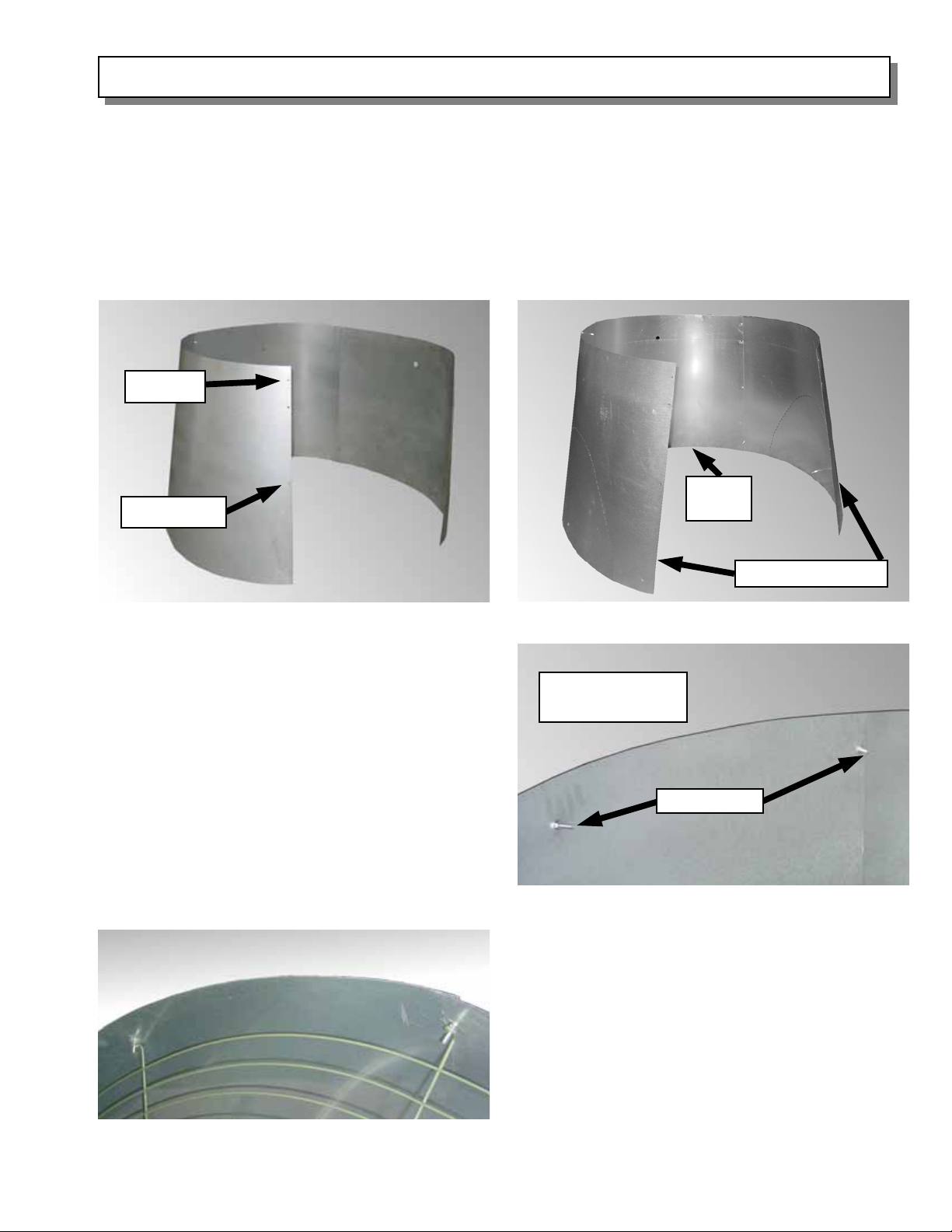
CONE ASSEMBLY
The discharge cone consists of four cone quarter panels. Begin construction by placing two
cone quarter panels such that the edges overlap and the four holes on the overlapping edges are
aligned, with the larger cone diameter down. Using top and middle overlapping holes in the
panels, fasten the cone panels together using two 1/4” X 1-1/4” bolts pushed from the inside
out, and two 1/4” whiz-lock nuts. Tighten the fasteners in the top holes securely, but only fingertighten the hardware in the middle set of holes at this time. Repeat this process for the third and
fourth panels until the cone is completed. Note that for the 60” Max Cone, the perforated cone
panels must be opposite each other. See Figure 6 for details.
Top Hole
Bottom
Middle Hole
Panel
Figure 6A — Standard Cone Assembly
Next, invert the cone so that the larger
diameter is up. Insert the four 1/4” X 1-1/4”
bolts into the overlapping holes on the edge of
the cone from the outside in, and place a
1/4” whiz-lock nut on each, creating the guard
studs. Also, insert one 1/4” X 1-1/4” bolt into
the hole at the top-middle of each cone panel
from the outside in and thread a 1/4” whizlock nut onto each, as shown in Figure 7.
Then, tighten all of the 1/4” cone hardware
securely. The guard is now ready to be
mounted.
Figure 8
Perforated Panels
Figure 6B — 60” Max Cone Assembly
Large Diameter
Cone Edge
Guard Studs
Figure 7
Take the guard, and with the eyelets at the
ends of the guard ribs pointing out of the
cone, slide the guard inside the cone. The
eyelets at the end of the guard ribs should be
placed over the guard studs (in 8 places for
the standard cone and 6 places for the 60”
Max Cone). With the guard in place, a 1/4”
whiz-lock nut may be placed on the guard
studs to secure the guard in place.
PAGE 5
Page 6
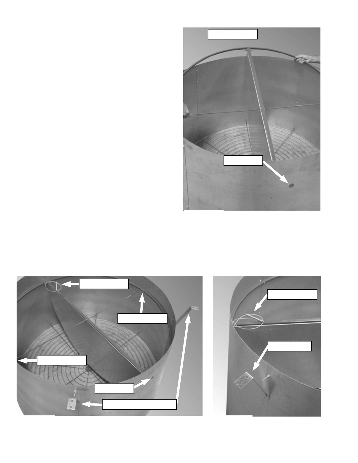
Once the guard is in place, the damper door ring
Door Cable End
assembly should be fastened to the cone. First,
invert the cone again so that the guard end is on
the ground. Take the damper door assembly,
making sure the doors opening downward, and
insert it at an angle into the cone as shown in
Figure 9. The end with the door restraining cable
should be opposite the drain hole in the cone.
Once the entire ring assembly has been placed
inside the cone, level the ring and align the predrilled ring holes with the corresponding
overlapping holes in the cone. From the inside of
the assembly, place a 1/4” X 1-1/4” bolt through
the holes in the 3-o'clock and 9-o’clock positions
(locating the drain hole at the 6-o’clock position)
and fasten with two 1/4” whiz-lock nuts.
Drain Hole
Next, the cone gussets will be placed on the
cone. NOTE: there are two sets of two gussets.
The longer set will have a notch on the end with
two holes. The longer set should be placed on
either side of the cone drain hole (cone bottom).
The shorter set of gussets should be placed
opposite the drain hole (cone top). To attach a
Figure 9
gusset, align the hole in the long flange with the
hole in the assembly ring and in the cone at the 45° angles. Push a 1/4” X 1-1/4” bolt through the
assembly ring, through the cone, and through the gusset. Fasten the bolt with a 1/4” whiz-lock
nut. Repeat this process for the three other gussets. Refer to Figures 10 and 11 for details.
Door Cable
3-O’Clock Hole
9-O’Clock Hole
Drain Hole
Long (Notched) Gussets
Figure 10 Figure 11
PAGE 6
Door Cable
Short Gusset
Page 7
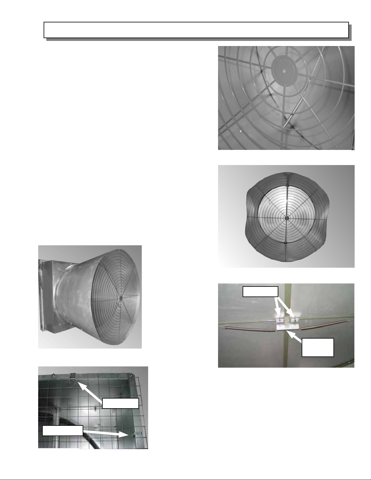
CONE AN D GUARD MOUNTING
To mount the cone assembly, pick the assembly up
and slide the smaller end over the fan panel orifice.
Make sure that the drain hole in the cone is at the
bottom. Fasten the gussets to the fan panel using
1/4” X 1-1/4” bolts and 1/4” whiz-lock nuts. Once
the cone assembly is secured in place, take the
spring at the end on the door restraining cable, and
attach it to vertical guard rib below the 3rd ring (from
the center) of the guard. See Figure 12.
For the 60” Max Cone, press the perforated sides
of the cone inward so that the guard studs protrude
through the guard eyelets and place a whiz-lock nut
on the stud and tighten securely. Figure 13 shows
the installed guard for the 60” Max Cone.
Next, mount the spring bracket at the center of the
door ring assembly where the struts intersect. Use
two cable ties to secure spring bracket as shown in
Figure 14. Attach one end of each spring to the
spring bracket. The other end of each spring should
be attached to the inside door hole in the damper
door.
Figure 12 — Door Restraining Cable
Figure 15 — Assembled Std. Unit
Guard Clip
Guard Latch
To check for
proper damper
operation, open
the doors fully,
and allow them
Figure 13 — 60” Max Cone & Guard
to close. If either
door fails to
Cable Ties
close properly,
rotate the
assembly slightly
on the fan orifice
until both doors
will close
properly.
Figure 14 — Spring and Bracket Assembly
Spring
Bracket
Once the unit is assembled, the inlet guard must be in place
before operation. To mount the guard, center it over the fan
housing. Then, slip the guard over the two guard clips on
the top housing flange. To secure the guard, close the 6
guard latches over the guard wire. The unit is no w ready for
operation. See Figure 16 for details.
Figure 16
PAGE 7
Page 8
BLADE AND BELT ALIGNMENT INSTRUCTIONS
Spin the blade assembly by hand. Make
sure that the blade assembly rotates freely
and did not shift during shipment. If the
blades rub in either side of the fan orifice, it
will be necessary to loosen the two (2) 3/8”
bolts that secure the blade assembly’s
hexagonal shaft to the fan x-braces, center
the blade assembly, and tighten the bolts
to 25-30 ft-lbs torque. If the blades rub in
the fan orifice at the top or bottom, it will be
necessary to loosen the four (4) 3/8” bolts
that secure the fan x-braces to the fan
uprights, center the blade assembly, and
tighten the bolts to 25-30 ft-lbs torque.
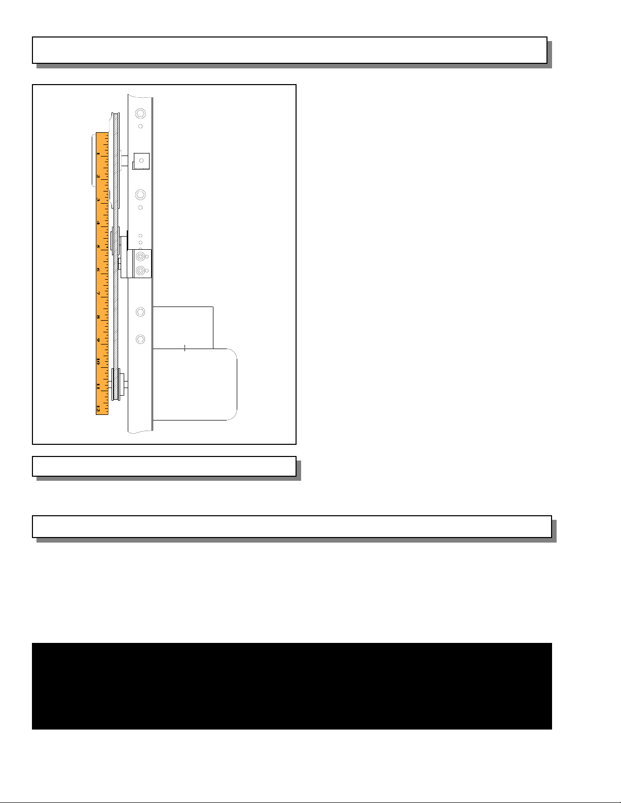
Next, the fan drive assembly should be
checked for alignment. The fan drive
assembly must be aligned for proper fan
performance and to minimize pulley and
belt wear. Before wiring and operating the
fan, check that the drive pulley, driven disc
and auto belt tensioner are aligned by
using a straight edge such as a scale or
yard stick. If an adjustment is necessary,
loosen the set screw on the motor pulley
and adjust to proper alignment. Make sure
Figure 17
to retighten the motor pulley set screw
before the fan is operated. See Figure 17.
Detailed View of Properly Aligned Fan Sheaves
ELECTRICAL WIRING
All wiring must comply with national, state and local electrical codes. If fans are to be used for
livestock ventilation to support life where failure could result in loss or injury, and continuous
ventilation is essential, it is recommended that the fans be wired to individual electrical circuits,
or at least two circuits per room. Any minimum ventilation fans should be on individual circuits.
WARNING
If the fans are going to be used for livestock building ventilation to support life where
failure could result in loss or injury, the user must provide an adequate backup
ventilation system and a failure alarm system. The user must accept the risk of such
loss or injury from failure of the ventilation system.
PAGE 8
Page 9
AUTO BELT TENSIONER BELT TENSION INSTRUCTIONS
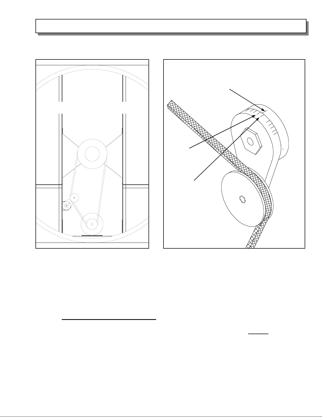
NOTE: The Auto Belt Tightener comes standard with Models MNBRDD52, MNBCDD52, and is
an optional accessory for Model MNCFDD52.
Front
View
Blades removed for clarity of detail
Alignment mark
Mark 2
Mark 1
Figure 18 — Motor/Pulley, Tensioner, Disc
and Belt
Figure 19 — Tensioner and Belt Showing Tension
Alignment Marks
For models MNBRDD52 and MNBCDD52, the Auto Belt Tensioner comes from the factory
mounted and preset for adequate belt tension. If further tensioning is required, loosen the 3/8 ”
bolt holding the tensioner to the tensioner bracket. Then, using a 15/16” wrench, rotate the
tensioner assembly such that the alignment mark is between mark 1 and 2 on the idler arm
(see Figure 19). Re-tighten the 3/8” bolt. Turn the blade assembly by hand to insure free
rotation. Do Not Over Tension The Belt
. This will cause premature belt and bearing failure.
To check that the belt tension is not too high, place a finger midway between the fan pulley
and motor pulley and push inward about 1/2”. The force required to do this is not
to exceed 5
pounds.
If an Auto Belt Tensioner is ordered for use with an Model MNCFDD52 fan, use the
instructions included in the ABT packaging for proper installation and use.
PAGE 9
Page 10
CONSTRUCTION FOR WINTER WEATHER PROTECTION
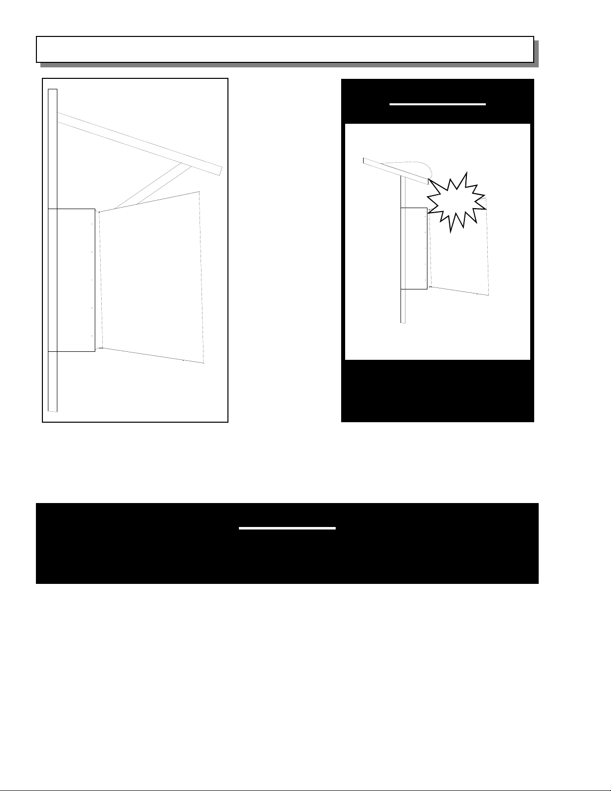
WARNING
Protect
Fan and Cone from Snow
Figure 20
If your area is subject to snow, consideration must be taken to protect from the possibility of
snow and ice building up on the roof and sliding down onto the fan and cone. One option is to
build a small section of roof over the fan and cone. See Figure 20.
and Ice Buildup
WARNING
Fan and/or cone damage caused by this type of external source WILL NOT
be covered by AMERICAN COOLAIR warranties.
During winter months, you may not need to operate all of your fans. It is advisable to seal up
those fans which will not be used during the colder months to minimize heat loss as well as
condensation. To do this, turn the fan control off, and insulate the fan intake.
PAGE 1 0
Page 11
INITIAL STARTUP
1. With inlet guard not installed, spin the blade assembly by hand and make sure that the
blade assembly rotates freely and did not shift during shipment. If the blades rub in the fan
housing, refer to page 8 for instructions on centering the blade assembly.
2. Check belt for proper tension.
3. Check motor pulley, driven disc and idler pulley (if present) for proper alignment.
4. Check circuit phase, voltage and wiring connection against that shown on motor nameplate.
5. Check for correct fan rotation.
6. Replace the inlet guard. The fan is now ready for proper operation.
MAINTENANCE
CLEANING
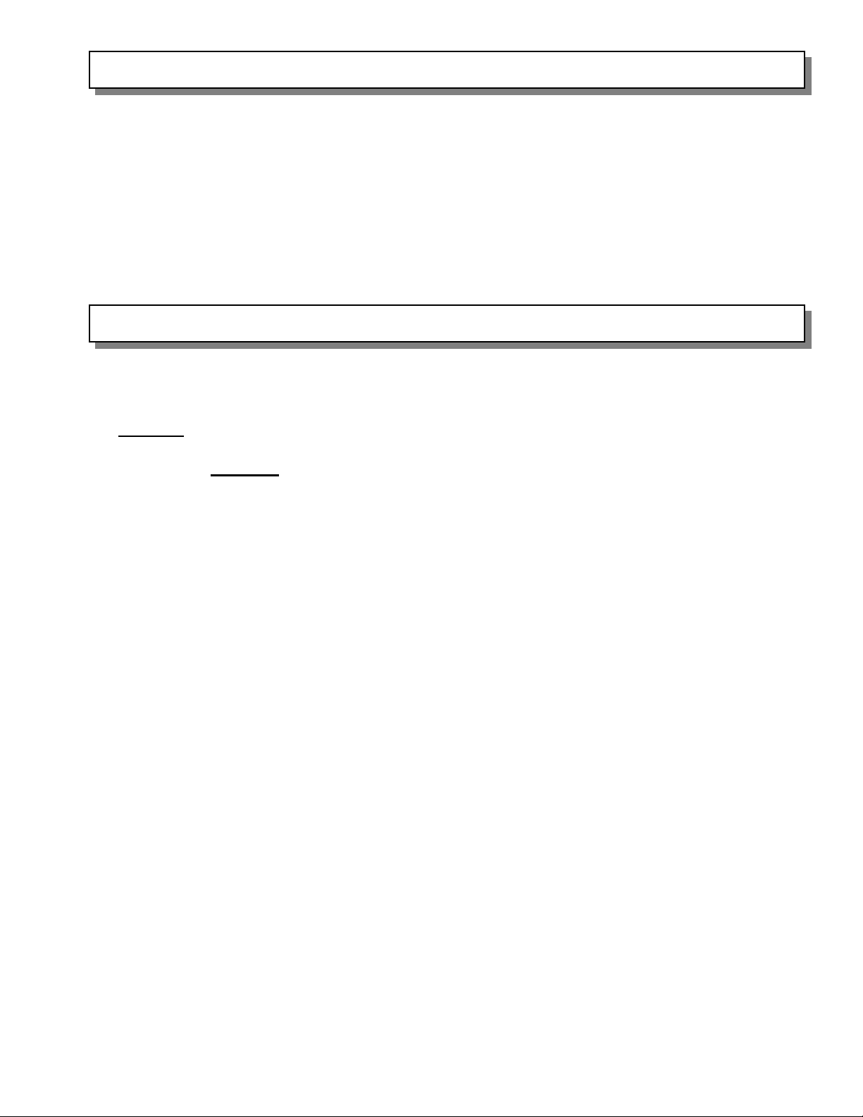
• The fan should be cleaned regularly. Always turn the fan off before cleaning.
• The motor should be wiped with a cloth or a brush. This will keep the motor running cool.
DO NOT pressure wash the motor.
• The blades should be wiped clean to maintain maximum air p erformance and minimize fan
imbalance. DO NOT pressure wash the center of the disc assembly, or premature bearing
failure may be induced.
• The damper door assembly should be wiped clean so that the doors will pi vot freely, open
completely, and close securely.
CHECK FASTENERS
Inspect all fasteners on the fan. This is a very important safety issue. If any loose hardware is
found, tighten it immediately.
CHECK BELT TENSION
The belt must have proper tension to insure proper fan speed and maximum air performance.
CHECK DRIVE ALIGNMENT
The belt must be properly aligned in the pulleys to minimize pulley and belt wear. Refer to
page 8 for instructions.
CHECK DOOR-RING GASKET
The door-ring is lined with a foam rubber gasket material. This gasket provides a seal between
the door-ring and the doors, insuring proper door function and minimizing air leakage. This
gasket should be checked periodically to make sure it is intact and properl y sealed to the doorring. If the material should come loose from the door-ring, it must be re-sealed to the door-ring
with appropriate adhesive.
PAGE 11
Page 12
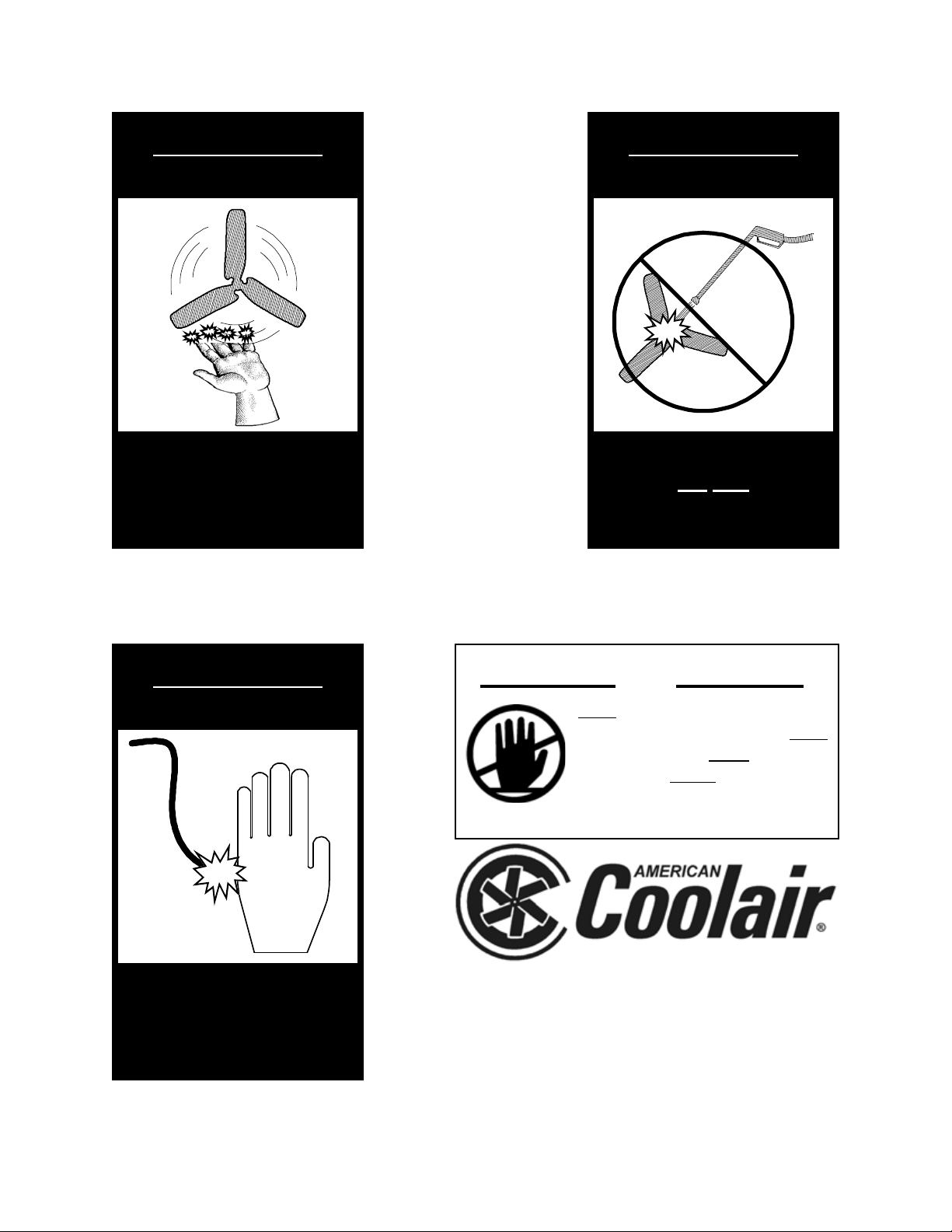
WARNING
WARNING
—– Moving Parts —–
Disconnect power
before servicing the
fan
WARNING
Precision Bearings
Not
Do
Pressure Wash at
blade assembly center
WARNING CAUTION
—– High Voltage —–
Disconnect power
before servicing the
fan
DO NOT INSTALL FAN WITH MOVING PARTS WITHIN 8
FEET OF FLOOR OR GRADE LEVEL WITHOUT A GUARD
THAT COMPLIES WITH OSHA REGULATIONS. DO NOT
USE UNLESS ELECTRICAL WIRING COMPLIES WITH
ALL APPLICABLE CODES. DO NOT WIRE WITHOUT
PROVIDING FOR A POWER SOURCE DISCONNECT AT
THE FAN ITSELF. DO NOT SERVICE EXCEPT BY A
QUALIFIED MAINTENANCE TECHNICIAN AND ONLY
AFTER DISCONNECTING THE POWER SOURCE.
FAILURE TO OBSERVE THESE PRECAUTIONS CAN
RESULT IN SERIOUS INJURY OR DEATH.
FARM PRODUCTS DIVISION
AMERICAN COOLAIR CORPORATION
PHONE (904) 389-3646 FAX (904) 387-3449
MEMBER OF AMCA
P.O. BOX 2300
JACKSONVILLE, FLORIDA 32203
E-MAIL - [email protected]
Form 910-25-7 (June, 2013)
 Loading...