

Page 1

FARM PRODUCTS DIVISION
AMERICAN COOLAIR CORPORATION
PHONE (904) 389-3646 FAX (904) 387-3449
MEMBER OF AMCA
P.O. BOX 2300
JACKSONVILLE, FLORIDA 32203
E-MAIL - [email protected]
MNBCC54 and MNEFC54
GALVANIZEDWALL FANS
Installation, Operation, and Maintenance Instructions
611/
585/
8
381/
4
701/
4
Figure 1 Dimensions in inches.
2
587/
21/
8
613/
4
8
MNBCC54L * MNBCCE54L * MNBCC54M
MNBCCE54M * MNEFC54L * MNEFCE54L
MNEFC54M * MNEFCE54M
UNPACKING
Inspect the fan for signs of shipping damage. It is the responsibility of the customer to report any shipping damage
to the freight carrier.
WHAT SHOULD YOU FIND?
Fan, Fan Housing (4 Housing Sheets, 4 Corner Deflectors, and 4 Shutter Latches), Cone (4 Cone Panels and 4
Cone Gussets), Cone Guard, Shutter with 4 Inlet Angles, and Hardware.
Page 2
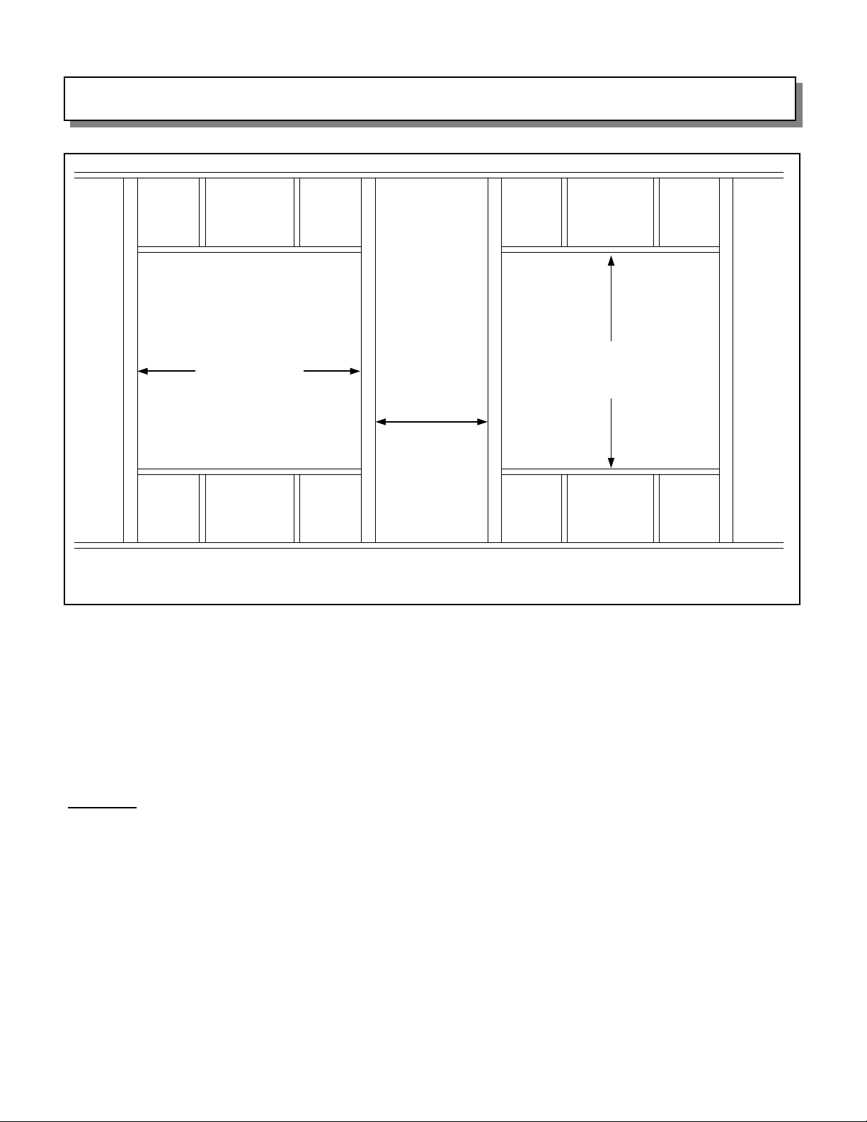
FRAME CONSTRUCTION
59 5/8” Width
Spacing
(see below)
Figure 2
The required framed-in opening width for both the MNBCC54 and MNEFC54 is 59 5/8”. The required framed-in
opening height depends on wall thickness:
For 2” thick walls, the height is 59 7/8”.
For 4” thick walls, the height is 60”.
For 6” thick walls, the height is 60 1/4”.
The minimum spacing between fans is 15”. However, to insure optimum fan performance, Coolair recommends a
spacing between fans of at least 30”.
Height
(see below)
CAUTION: To insure proper fan and shutter operation, the frame opening MUST BE SQUARE. To verify this,
measure from the upper right corner of the frame diagonally to the lower left corner. Next, measure from the upper
left corner of the frame diagonally to the lower right corner. These two DIAGONAL MEASUREMENTS MUST BE
EQUAL prior to installing the fan.
PAGE 2
Page 3
FAN & HOUSING ASSEMBLY
For assembly and maintenance instructions for the fan and motor, see Form 220-40 included with the fan.
If the fan and housing are factory assembled, skip to Page 4 — Fan Mounting & Installation. For the
proper mounting of the motor bracket to the fan frame, disregard Figure 1 on Form 220-40 and install the motor
bracket towards the top of the fan — see Figure 4. Make sure the motor is mounted on top of the motor bracket.
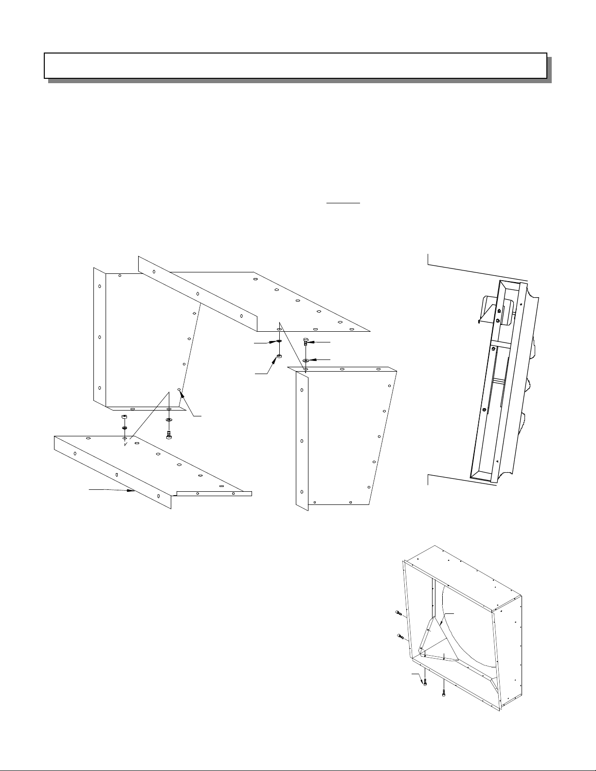
There are 4 wall housing sheets -- the two that are the same size are the side sheets. The smaller rectangular sheet
is the bottom. The larger rectangular sheet is the top. Assemble the bottom and one side sheet together using 1/4"
hardware as shown in Figure 3. Then, place the fan on the bottom housing sheet aligning the holes in the fan
flanges with the fan mounting holes in the wall housing sheets. Caution: for proper shutter clearance, the fan must
be mounted in the housing with the motor at the top of the housing as shown in Figure 4. Now, assemble the
remaining housing sheets around the fan using 1/4" nuts and bolts for the housing assembly and for mounting the
fan panel to the housing. When assembling the wall housing, do not tighten any hardware until all bolts are in place.
Top
Sheet
(Left) Side
Sheet
¼” Lock
Washer
¼” Nut
Fan
Mounting
Holes
Bottom
Sheet
Housing
Mounting
Flange
Figure 3 — Housing Assembly
CORNER DEFLECTOR INSTALLATION: For proper fan
operation, the corner deflectors must be fastened to the fan.
There are two sizes of these triangular deflectors — the longer
deflectors will be installed in the top two corners where the fan
panel meets the housing, and the shorter deflectors will be
installed in the bottom two corners.
First, place the deflector inside the housing such that the two
shorter sides (with the flanges and mounting holes) are against
the housing, and the longer side is against the fan panel. The
holes in the deflectors should align with the holes in the housing.
If the holes are not aligned, check that you are using the correct
length deflector in the proper corner. Fasten each deflector
using four of the ¼” x ¾” self-tapping screws provided. The
screws must be fastened from the outside of the housing through
the housing and then through the deflector. See Figure 5.
¼” x ¾” Bolt
¼” Flat Washer
(Right) Side
Sheet
Figure 4 — Side view of
the fan assembled in the
housing
Corner
Deflector
¼” x ¾” Self-
Tap Screws
Figure 5
PAGE 3
Page 4
FAN MOUNTING & INSTALLATION
For motor mounting instructions, please refer to the accompanying Form #220-43.
From the inside of the building, insert the fan/housing through the opening. Before fastening the fan to the building,
the fan housing MUST BE SQUARE IN THE FRAME to insure proper fan and shutter operation. To verify this,
measure from the upper right corner of the fan housing diagonally to the lower left corner. Next, measure from the
upper left corner of the fan housing diagonally to the lower right corner. These two DIAGONAL MEASUREMENTS
MUST BE EQUAL prior to installing the fan. If the two diagonal measurements are not equal, the fan must be
shimmed to bring it into square.
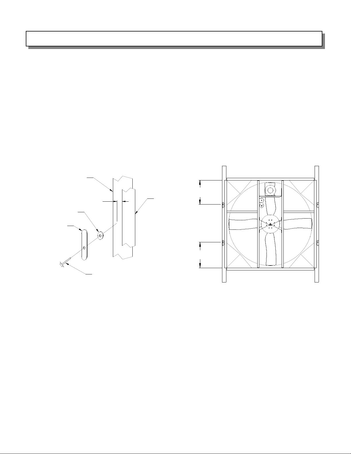
Once that the housing has been squared, secure the fan to the building frame (hardware not provided). Next, using
the 1/4” Lag Screws and Rubber Washers, install the Shutter Latches to the building frame 3/8” away from the fan
housing flange as shown in Figure 6. The Shutter Latches should be located approximately 20 inches from the top
and bottom of the housing (See Figure 7).
Building Frame
Fan
3/8”
Rubber Washer
Shutter Latch
1/4” Lag Screw
Figure 6
For cone assembly and mounting instructions, refer to the accompanying Form #401-276.
Housing
Flange
20”
20”
Figure 7
PAGE 4
Page 5
BLADE AND BELT ALIGNMENT INSTRUCTIONS
Spin the blade assembly by hand.
Make sure that the blade assembly
rotates freely and did not shift during
shipment. If the blades rub in either
side of the fan orifice, it will be
necessary to loosen the two (2) 3/8”
bolt s that secure the blade
assembly’s hexagonal shaft to the fan
x-braces, center the blade assembly,
and tighten the bolts to 25-30 ft-lbs
torque. If the blades rub in the fan
orifice at the top or bottom, it will be
necessary to loosen the four (4) 3/8”
bolts that secure the fan x-braces to
the fan uprights, center the blade
assembly, and tighten the bolts to 25-
30 ft-lbs torque. Next, the fan drive
assembly should be checked for
alignment. The fan drive assembly
must be aligned for proper fan
performance and to minimize pulley
and belt wear. Before wiring and
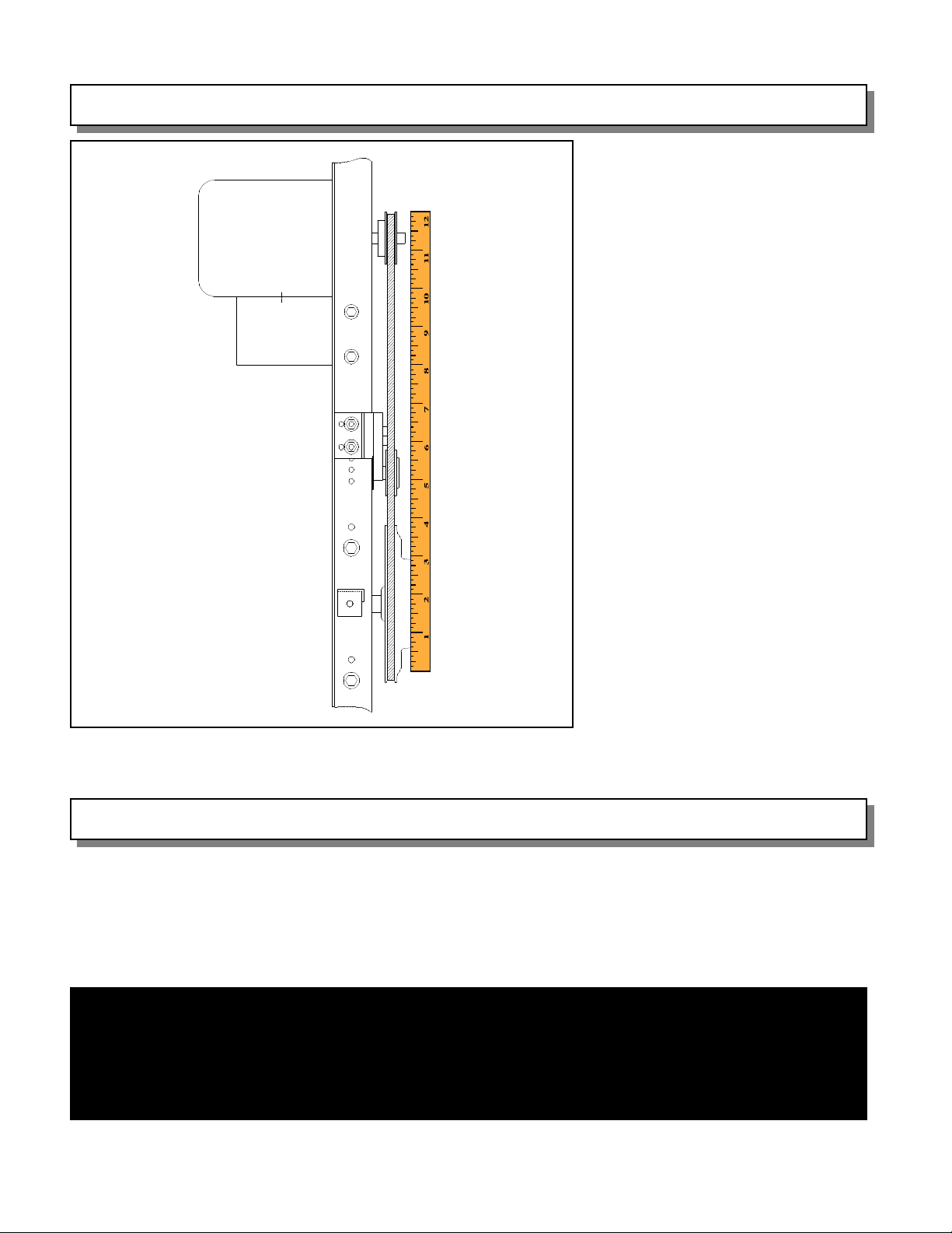
operating the fan, check that the drive
pulley, driven disc and auto belt
tensioner are aligned by using a
straight edge such as a scale or yard
stick. If an adjustment is necessary,
loosen the set screw on the motor
pulley and adjust to proper alignment.
Make sure to retighten the motor
pulley set screw before the fan is
operated. See Figure 8.
Figure 8 — Detailed View of Properly Aligned Fan Sheaves
ELECTRICAL WIRING
All wiring must comply with national, state and local electrical codes. If fans are to be used for livestock ventilation
to support life where failure could result in loss or injury, and continuous ventilation is essential, it is recommended
that the fans be wired to individual electrical circuits, or at least two circuits per room. Any minimum ventilation
fans should be on individual circuits.
WARNING
If the fans are going to be used for livestock building ventilation to support life where
failure could result in loss or injury, the user must provide an adequate backup
ventilation system and a failure alarm system. The user must accept the risk of such
loss or injury from failure of the ventilation system.
PAGE 5
Page 6
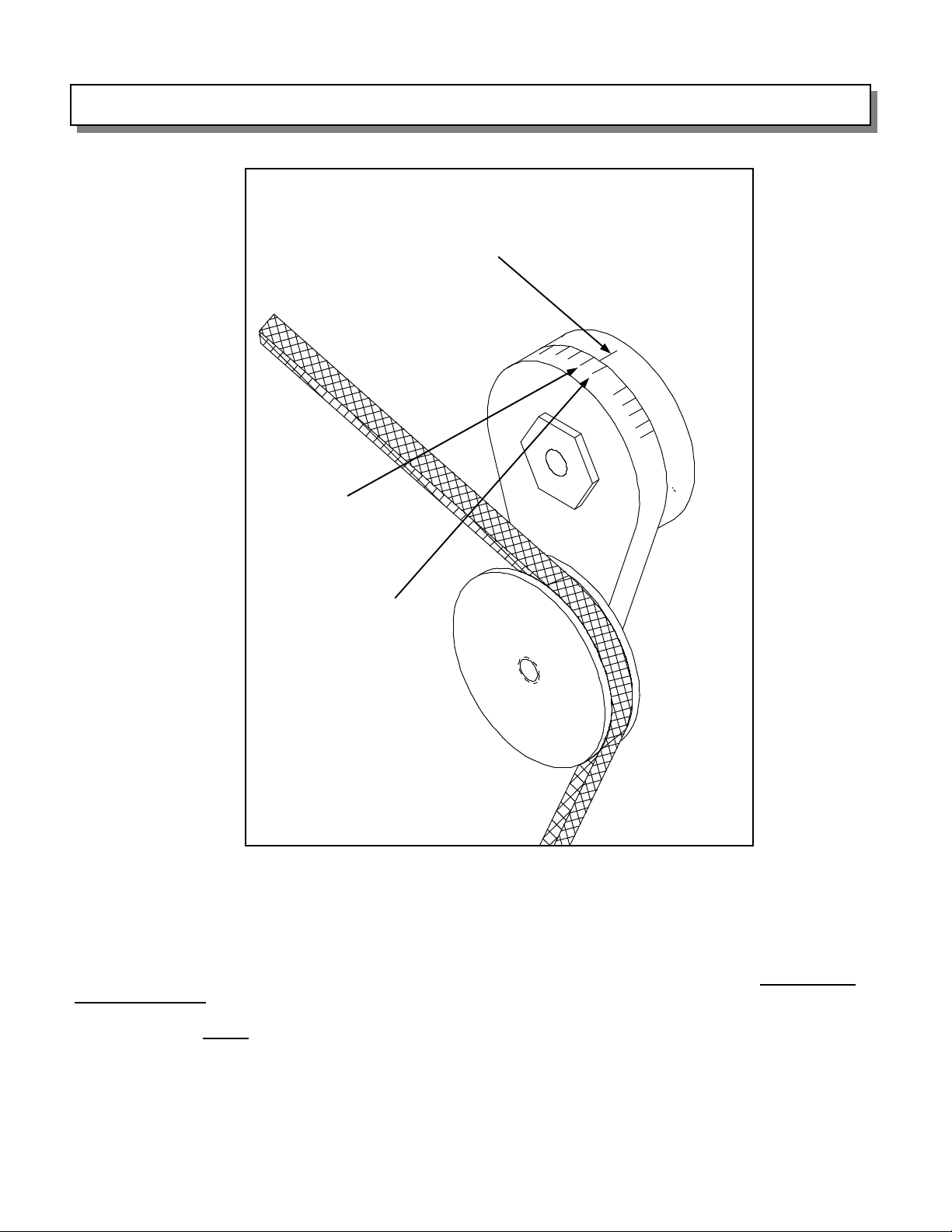
AUTO BELT TENSIONER BELT TENSION INSTRUCTIONS
Alignment mark
Mark 2
Mark 1
Figure 9 — Tensioner and Belt Showing Tension Alignment Marks
The Auto Belt Tensioner comes from the factory mounted and preset for adequate belt tension. If further
tensioning is required, loosen the 3/8” bolt holding the tensioner to the tensioner bracket. Then, using a 15/16”
wrench, rotate the tensioner assembly such that the alignment mark is between mark 1 and 2 on the idler arm
(see Figure 9). Re-tighten the 3/8” bolt. Turn the blade assembly by hand to insure free rotation. Do Not Over
Tension The Belt. This will cause premature belt and bearing failure. To check that the belt tension is not too
high, place a finger midway between the fan pulley and motor pulley and push inward about 1/2”. The force
required to do this is not to exceed 5 pounds.
For further information, refer to the accompanying Form #912-19.
PAGE 6
Page 7
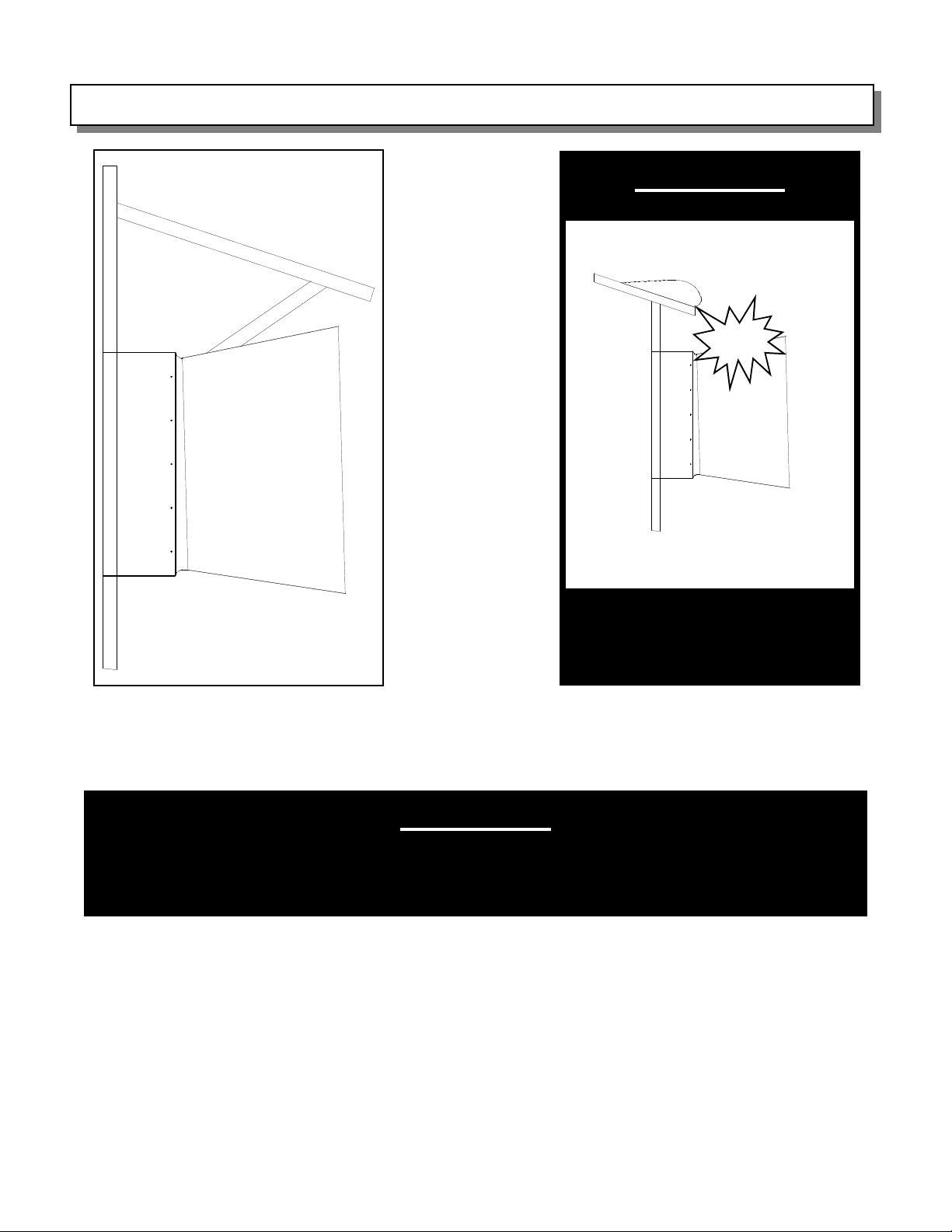
CONSTRUCTION FOR WINTER WEATHER PROTECTION
WARNING
Protect
Fan and Cone from Snow
Figure 10
If your area is subject to snow, consideration must be taken to protect from the possibility of snow and ice
building up on the roof and sliding down onto the fan and cone. One option is to build a small section of roof over
the fan and cone. See Figure 10.
and Ice Buildup
WARNING
Fan and/or cone damage caused by this type of external source WILL NOT
be covered by AMERICAN COOLAIR warranties.
During winter months, you may not need to operate all of your fans. It is advisable to seal up those fans which
will not be used during the colder months to minimize heat loss as well as condensation. To do this, turn the fan
control off, and insulate the fan intake.
PAGE 7
Page 8
INITIAL STARTUP
1. With the shutter not installed, spin the blade assembly by hand and make sure that the blade assembly rotates
freely and did not shift during shipment. If the blades rub in the fan housing, refer to Page 5 for instructions on
centering the blade assembly.
2. Check belt for proper tension.
3. Check motor pulley, driven disc and idler pulley for proper alignment.
4. Check circuit phase, voltage and wiring connection against that shown on motor nameplate.
5. Check for correct fan rotation.
6. Replace the shutter. The fan is now ready for proper operation.
MAINTENANCE
CLEANING
The fan should be cleaned regularly. Always disconnect power to the fan before cleaning.
The motor should be wiped with a cloth or a brush. This will keep the motor running cool. DO NOT pressure
wash the motor.
The blades should be wiped clean to maintain maximum air performance and minimize fan imbalance. DO
NOT pressure wash the center of the disc assembly, or premature bearing failure may be induced.
The shutter blades should be wiped clean so that they will pivot freely, open completely, and close securely.
CHECK FASTENERS
Inspect all fasteners on the fan. This is a very important safety issue. If any loose hardware is found, tighten it
immediately.
CHECK BELT TENSION
The belt must have proper tension to insure proper fan speed and maximum air performance.
CHECK DRIVE ALIGNMENT
The belt must be properly aligned in the pulleys to minimize pulley and belt wear. Refer to Page 5 for instructions.
Precision Bearings
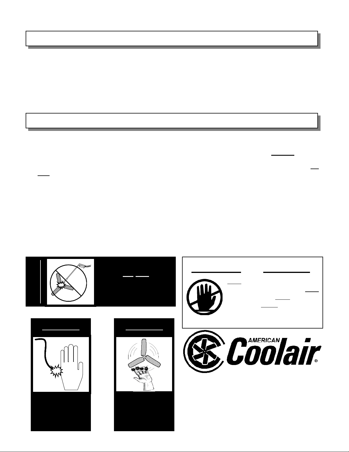
WARNING CAUTION
Do Not
DO NOT INSTALL FAN WITH MOVING PARTS WITHIN 8
FEET OF FLOOR OR GRADELEVEL WITHOUT A GUARD
THAT COMPLIES WITH OSHA REGULATIONS. DO NOT
USE UNLESS ELECTRICAL WIRING COMPLIES WITH
ALL APPLICABLE CODES. DO NOT WIRE WITHOUT
PROVIDING FOR A POWER SOURCE DISCONNECT AT
THE FAN ITSELF. DO NOT SERVICE EXCEPT BY A
QUALIFIED MAINTENANCE TECHNICIAN AND ONLY
AFTER DISCONNECTING THE POWER SOURCE.
FAILURE TO OBSERVE THESE PRECAUTIONS CAN
RESULT INSERIOUS INJURY ORDEATH.
AMERICAN COOLAIR CORPORATION
MEMBER OF AMCA
P.O. BOX 2300
JACKSONVILLE, FLORIDA 32203
E-MAIL - [email protected]
Form 910-46-2 (August, 2012)
WARNING
DANGER
– High Voltage –
Disconnect
power before
servicing the fan
Pressure Wash at
blade assembly
center
DANGER
– Moving Parts –
Disconnect
power before
servicing the fan
FARM PRODUCTS DIVISION
PHONE (904) 389-3646 FAX (904) 387-3449
 Loading...