

Page 1
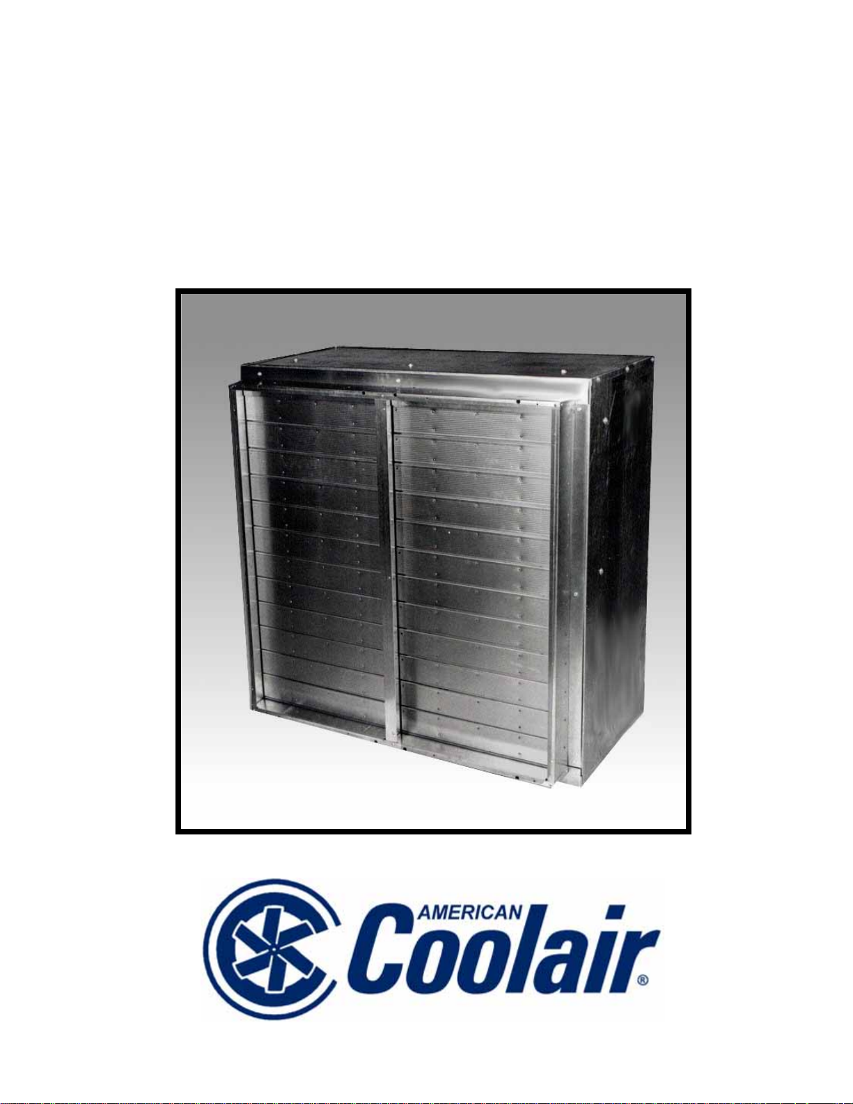
Type MB
Wall Fan Packages
Page 2
Type MB Fan Packages
Application: Versatile
T ype MB fan packages have been specifically
designed for use with C-fans ranging in size from
24 to 60 inches. The design allows for more
versatility of use in all applications where a
complete fan package is desired. These complete
packages greatly simplify the specification and
use of ventilation equipment in commercial and
industrial metal buildings.
Fan packages are shipped completely
assembled and each package includes fan,
shutter, guard, and housing as standard.
By expanding upon the original design to allow
for flexible usage, American Coolair MB fan
packages are now more practical and efficient for
use in supply or exhaust applications.
Drive Mechanism: Unique
Type MB Belt drive models are designed for
quiet operation and low initial cost, using a variety
of available motors. Each model incorporates a
unique American Coolair fan bearing and shaft
assembly whereby a shaft is mounted on a crossframe member and the power is applied directly to
a cast aluminum hub. Drive belt power is applied
to the fan/hub assembly in the same plane as the
bearings. This reduces bearing load and
dramatically increases fan life. Bearings are
permanently lubricated and sealed.
Most models are equipped with a variable
pitch motor pulley which allows fan speed
adjustment where desirable.
The setting made at the factory operates the
fan at the maximum safe load of the motor. The
pulley may be opened to reduce fan speed and
thus decrease air flow and sound levels.
If an increase in fan speed is desired, contact
your American Coolair representative for
information on fan performance and motor load
before making any adjustment.
Construction: Rigid, Long-Lasting
The wall housing is fabricated of galvanized
steel for rigidity, long life and years of protection
against rust and corrosion. An exterior finish coat
of epoxy can be specified.
Type MB fan packages feature aluminum
shutters with reinforced interlocking blades.
The fan panel is fabricated of heavy-gauge
steel, and the uprights which support the motor
and propeller are formed from heavy-gauge steel
angle for maximum strength and rigidity.
• The fan panel assembly, mounted in the wall
housing, utilizes all-welded construction.
• The deep spun venturi orifice is specifically
engineered to provide maximum efficient air
movement and quiet operation.
• The shutter is counterbalanced for automatic
(gravity) operation.
• All propeller blade assemblies are dynamically
balanced.
• Parts requiring painting are processed through
the advanced American Coolair multi-stage
pretreatment system prior to the application of
any coatings to ensure maximum finish
adhesion. For additional protective coating
options, see the Accessories section on Page
6.
Motors: Efficient, Economical
American Coolair’s air-over-motor design
provides extra capacity and economy because air
velocity over motor is used to dissipate heat and
thus increase horsepower capability.
Totally-enclosed motors are standard f or MB
fan packages. Several motor alternatives are
available to fit your specific needs such as
explosion-proof, energy-efficient, and severe-duty.
Only nationally recognized brand motors with
nationwide service facilities are used.
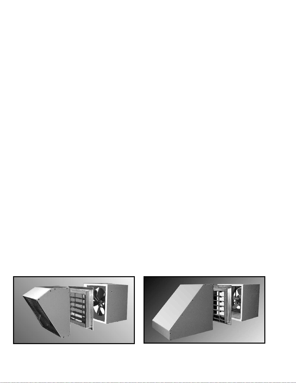
MB fan package for exh aust with optional di sc harge
hood
2
MB fan package for supply with optional inlet hood
(for better all-weather prot ec tion in supply configuration,
a motorized SR or SU inlet shutter is reco mmended)
Page 3
Selection
The following are some of the basic
considerations in determining which model and
how many fan packages are needed for a specific
building. A more thorough discussion of the fan
selection is available in American Coolair’s
“Industrial and Commercial Ventilation
Handbook”. Factory-trained representatives are
also available locally to aid you. Simply consult a
business directory or visit us at coolair.com to find
an American Coolair representative in your area.
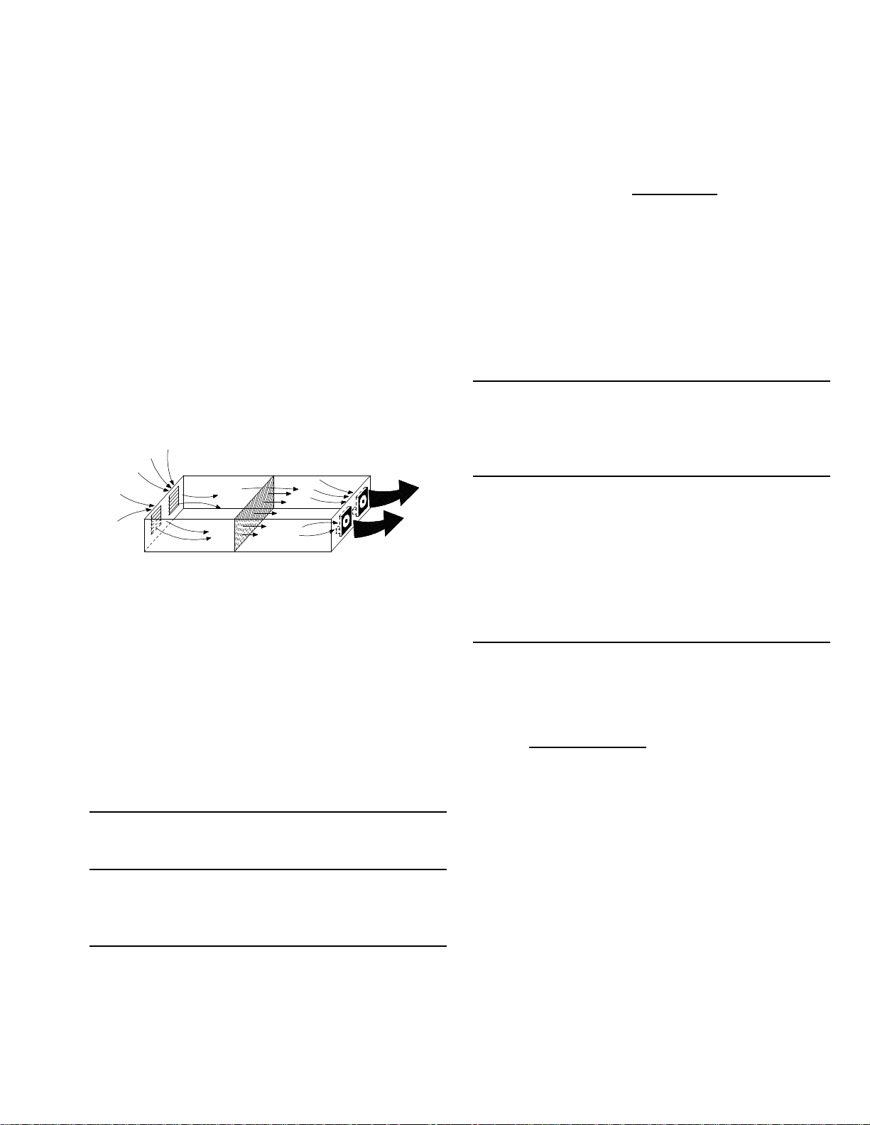
Fan Package Location
Fans should all be at one end of the building.
They may be in the end wall or in a sidewall near
the end. They should be located so that
equipment or stacks of material in the building will
not block airflow into the fans. If large doors are
going to be kept open in warm weather, fans
should be at the opposite end of the building from
the doors.
Calculation of Air Volume:
Rate of Air Velocity Method.
This is the method recommended by
American Coolair and will provide adequate air
movement to produce personnel comfort, not just
minimum ventilation.
CFM = H x W x V
Where: CFM is air volume in cubic feet per minute
H is the height of the building (ft.)
W is the width of the building (ft.)
V is the desired velocity (see table) (ft./min.)
VELOCITY TABLE
Length of Building Velocity
Up to 100’ 150 ft./min.
100’ to 200’ 200 ft./min.
200’ to 300’ 250 ft./min.
300’ and longer 250 ft./min plus booster fans
Example: Laundry 100’ long by 30’ wide by 15’
high. Air is to be pulled through the 100’ length.
CFM = 15’ x 30’ x 150 ft./min. = 67,500 cubic ft./
minute
Rate of Air Change Method.
This is the most common method of specifying
air volume for small buildings (50,000 cubic feet
or less). Rate can be specified for ventilation or
personnel comfort.
H x W x L
R
CFM =
Where:
CFM is air movement in cubic feet per minute
H is the height of the building (ft.)
W is the width of the building (ft.)
L is the length of the building (ft.)
R is the rate of air change in minutes (see table)
TYPICAL RECOMM E NDE D
AIR CHANGE RATES
Personnel
Type of Facility Comfort Ventilation
Bakeries, Restaurants,
Laundries & other
hot spots
Factories, Shops,
Warehouses & Garages
Residences, Schools, 1 minute 5 minutes
Offices & Churches
1
/2 minute 3 minutes
3
/4 minute 4 minutes
Example: Laundry 100’ long by 30’ wide by 15’
high — air is to be change to provide personnel
comfort:
15’ x 30’ x 100’
CFM =
1
/2 minute
= 90,000 cubic ft./minute.
Air Intakes
Provision must be made for air to enter the
building. Air intakes should be at the opposite
end of the building from the fans so that air
movement will occur throughout the building.
Wall louvers or roof mounted intakes can be used.
Your local American Coolair representative can
help you determine what is needed and provide
the proper intakes for you.
Sound
Sound ratings may also be a factor in fan
selection. These are provided in sones. If
additional information is needed, contact your
American Coolair representative.
3
Page 4

Performance
1
2
3
Typical Specifications
Ratings
Belt driven propeller wall fan packages shall be American Coolair Type MBA, MBL,
MBH, and MBHX as manufactured by American Coolair Corporation, Jacksonville,
Type MB fan ratings shown
herein are net performance of
complete fan package,
including the effects of the
shutter, wall housing, and
guard. The air and sound
performance ratings are based
on American Coolair’s Type CB
fans, which are licensed to bear
the AMCA Certified Ratings
Seal. BHP does not include
drive losses.
Item Fan Fan Motor Fan Sone Max Approx. Shutter
No. 0" 1/8" 1/4" 3/8" 1/2"
1 2,998 2,822 2,629 2,384 --- MBA18H
2 3,421 3,268 3,104 2,926 2,692 MBA18J
3 3,915 3,782 3,642 3,496 3,336 MBA18K
4 4,356 4,237 4,113 3,985 3,850 MBA18L 1 2,143 32 1.25 135 SU
5 3,082 2,822 2,537 --- --- MBA20G
6 3,383 3,147 2,903 --- --- MBA20H
7 3,870 3,664 3,455 3,227 --- MBA20J
8 4,418 4,238 4,055 3,871 3,663 MBA20K
9 4,910 4,748 4,584 4,420 4,251 MBA20L* 1 1,856 30 1.25 140 SU
10 5,444 5,298 5,151 5,003 4,854 MBA20M*
11 5,010 4,266 --- --- --- MBL24G
12 5,588 4,950 --- --- --- MBL24H
13 6,244 5,691 4,972 --- --- MBL24J
14 7,222 6,757 6,199 --- --- MBL24K
15 7,557 7,163 6,697 6,024 5,365 MBH24L* 1 1,065 28 1.25 246 S
16 8,345 7,990 7,599 7,078 6,439 MBH24M*
17 6,755 5,346 --- --- --- MBL30G
18 7,531 6,327 --- --- --- MBL30H
19 8,334 7,273 5,696 --- --- MBL30J
20 9,725 8,836 7,788 --- --- MBL30K
21 10,713 9,895 8,878 --- --- MBH30L 1 807 25 1.25 290 S
22 11,761 11,027 10,165 9,088 --- MBH30M
23 12,836 12,170 11,420 10,512 9,463 MBH30N 2 967 34 2.25 316 S
24 14,775 14,203 13,584 12,888 12,077 MBH30P* 3 1,113 48 3.31 334 SR
25 8,191 5,894 --- --- --- MBL36G
26 9,168 7,218 --- --- --- MBL36H
27 10,583 9,087 --- --- --- MBL36J
28 11,799 10,542 8,631 --- --- MBL36K
29 13,314 12,240 10,681 --- --- MBL36L 1 668 15.5 1.25 361 LRW
30 14,197 12,893 11,604 9,702 --- MBH36M
31 15,659 14,489 13,310 11,963 10,127 MBH36N 2 750 24 2.25 393 S
32 18,185 17,200 16,144 15,156 13,965 MBH36P 3 871 30 3.35 411 SR
33 21,296 20,474 19,567 18,467 17,847 MBH36Q* 5 1,020 43 5.25 438 SR
34 10,973 7,612 --- --- --- MBL42H
35 12,640 9,957 --- --- --- MBL42J
36 14,074 11,694 7,975 --- --- MBL42K
37 15,909 13,788 11,384 --- --- MBL42L 1 477 17.4 1.25 343 LRW
38 16,991 15,161 12,957 9,865 --- MBH42M
39 18,765 17,132 15,255 12,959 9,429 MBH42N 2 571 25 2.25 373 LRW
40 21,789 20,403 18,883 17,164 15,147 MBH42P 3 663 32 3.34 390 S
41 26,160 25,021 23,812 22,514 21,099 MBH42Q 5 796 44 5.53 417 SR
Cubic Feet Per Minute (CFM) at Static Pressure
Florida; specific model s sh all be as show n in the fan sche dul e. Fan packag es shall
include fan unit, wall housing, (automatic gravity) shutter, and 1 X 1/2” PVC coated
inlet guard. Panels and structural angle supports shall be of welded steel
construction with spun orifice to provide improved performance (MBL, MBH, &
MBHX). Die formed steel blades shall be firmly attached to cast aluminum hub,
which also serves as driven sheave. Fan hub shall rotate on fixed shaft using
oversized se a le d b a l l b ea r in g s. B e l t l oa d sh a l l be a pp l ied to hub in the same plane
as bearings, eliminating overhung load on bearings and increasing bearing life.
Motor pulleys shall be variable pitch (except where noted below). (Specify for each
fan model in schedule the required CFM and static pressure; motor enclosure,
phase and voltage; and accessories such as wall shutter, motor side or front guard,
wall housing, etc.)
Model
Size HP RPM
1
1,475 18.0 0.41 110 SU
/
3
1
1,683 23.0 0.61 116 SU
/
18
20
24
30
36
42
2
3
1,926 27 0.91 130 SU
/
4
1
1,165 13.9 0.31 115 SU
/
4
1
1,279 16.5 0.40 115 SU
/
3
1
1,463 21.0 0.61 121 SU
/
2
3
1,670 26 0.91 135 SU
/
4
1
1
1
1
1
1
2,058 36 1.70 162 SU
/
2
1
1
1
3
1
1
1
3
1
1
1
3
1
1
3
702 12.7 0.30 216 LRW
/
4
783 16.0 0.41 216 LRW
/
3
875 19.8 0.60 219 LRW
/
2
1,012 26 0.90 223 S
/
4
1
1,176 33 1.56 248 S
/
2
505 10.4 0.30 276 LRW
/
4
563 13.0 0.41 276 LRW
/
3
623 16.1 0.60 279 LRW
/
2
727 20 0.90 282 LRW
/
4
1
886 28 1.70 309 S
/
2
411 6.8 0.30 349 LRW
/
4
460 8.3 0.41 349 LRW
/
3
531 10.1 0.60 352 LRW
/
2
592 13.2 0.90 355 LRW
/
4
1
680 20 1.65 385 LRW
/
2
329 8.7 0.41 330 LRW
/
3
379 11.3 0.60 333 LRW
/
2
422 14.0 0.90 336 LRW
/
4
1
517 22 1.65 365 LRW
/
2
Rating
BHP
Ship Wt. Model
4
Page 5

Item Fan Fan Motor Fan Sone Max Approx. Shutter
1
2
3
*
*
*
No. 0" 1/8" 1/4" 3/8" 1/2"
42 15,084 11,079 --- --- --- MBL48J
43 17,382 14,225 --- --- --- MBL48K
44 19,441 16,686 --- --- --- MBL48L 1 406 16.9 1.25 403 LRW
45 20,722 18,318 14,065 --- --- MBH48M
46 23,014 20,899 17,851 --- --- MBH48N 2 472 23 2.25 438 LRW
Cubic Feet Per Minute (CFM) at Static Pressure
Model
Size HP RPM
1
3
1
315 10.6 0.60 393 LRW
/
2
363 14.1 0.90 396 LRW
/
4
1
425 19.6 1.66 431 LRW
/
2
48
Rating
BHP
Ship Wt. Model
47 26,183 24,351 22,184 18,520 --- MBH48P 3 537 29 3.34 455 LRW
48 30,912 29,374 27,734 25,701 22,536 MBH48Q 5 634 37 5.49 482 S
49 34,223 32,795 31,532 30,380 29,241 MBHX48R
50 37,531 36,214 35,030 33,944 32,914 MBHX48S
51 16,433 10,224 --- --- --- MBH54J
52 19,239 15,312 --- --- --- MBH54K
7 1/
10 817 57 10.39 812 SR
1
3
53 21,529 18,183 --- --- --- MBH54L 1 376 17.6 1.25 446 LRW
54 23,132 20,063 14,165 --- --- MBH54M
55 25,880 23,172 19,756 --- --- MBH54N 2 452 23 2.26 457 LRW
1
54
745 49 7.92 780 SR
2
287 11.1 0.60 432 LRW
/
2
336 14.6 0.91 439 LRW
/
4
1
404 19.5 1.68 450 LRW
/
2
56 29,201 26,824 24,208 19,549 --- MBH54P 3 510 28 3.35 484 LRW
57 35,736 33,713 31,531 28,908 --- MBHX54Q 5 547 33 5.37 775 S
58 41,485 39,756 37,943 35,982 33,671 MBHX54R
59 45,143 43,560 41,915 40,181 38,269 MBHX54S
60 25,107 19,853 --- --- --- MBHX60L 1 297 13.0 1.25 759 S
61 27,728 23,068 --- --- --- MBHX60M
1
7
635 43 8.39 832 SR
/
2
10 691 50 10.71 864 SR
1
1
328 15.7 1.66 771 S
/
2
62 30,264 26,137 21,017 --- --- MBHX60N 2 358 18.2 2.25 775 S
63 34,237 30,775 26,496 --- --- MBHX60P 3 405 21 3.19 793 S
64 40,746 37,992 34,490 30,948 --- MBHX60Q 5 482 28 5.40 820 S
65 47,171 44,861 42,092 38,908 35,891 MBHX60R
60
1
7
558 37 8.38 878 S
/
2
66 51,989 49,923 47,546 44,758 41,888 MBHX60S 10 615 45 11.04 911 SR
1 - The first three or four letters of model number identify fan type, drive configuration and style. The next two numbers indicate fan size; the
next letter identifies the motor horsepower. Example; Model MBL24G is Type M, belt drive, Style L, 24” size 1/4 HP.
2 - The sound ratings shown are loudness values in sones at 5 ft. (1.5m) in a hemispheri cal free field calculated per AMCA standard 301.
Values shown are for installation Type A: free inlet fan sone levels. The ratings shown are at 0” static pressure.
3 - Maximum brake horsepower (BHP) within the catalog perf ormance range. BHP does not include belt drive losses. Bearing losses are
included. BHP at most static pressures listed is less than sho wn, in some cases, substantially less. F or specific BHP values at individual
static pressure points, contact your American Coolair representative. Because of the cooling the motor receives f rom the moving airstrea m,
motor loading beyond the nominal nameplate rating on these American Coolair fans does not overheat the motor and is within NEMA
recommended limits and motor service factor. It is not detrimental to the motor and is economically desirable.
* - These models use fixed pitch motor pulleys.
To convert air performance (CFM and SP) and power (BHP) to metric units, multiply CFM x .000472 to obtain cubic
meters per second (CMS). Multiply SP x 248.36 to obtain Pascals (Pa). Multiply BH P x .7457 to obtain Kilowatts (kW).
Example: 3904 CFM x .000472 = 1.8427 C MS
0.125 SP x 248.36 = 31.05 Pa
0.886 BHP x .7457 = 0.661 kW
ALL SPECIFICATIONS SUBJECT TO CHANGE WITHOUT NOTICE
5
Page 6
PVC-Coated
Wire Guard
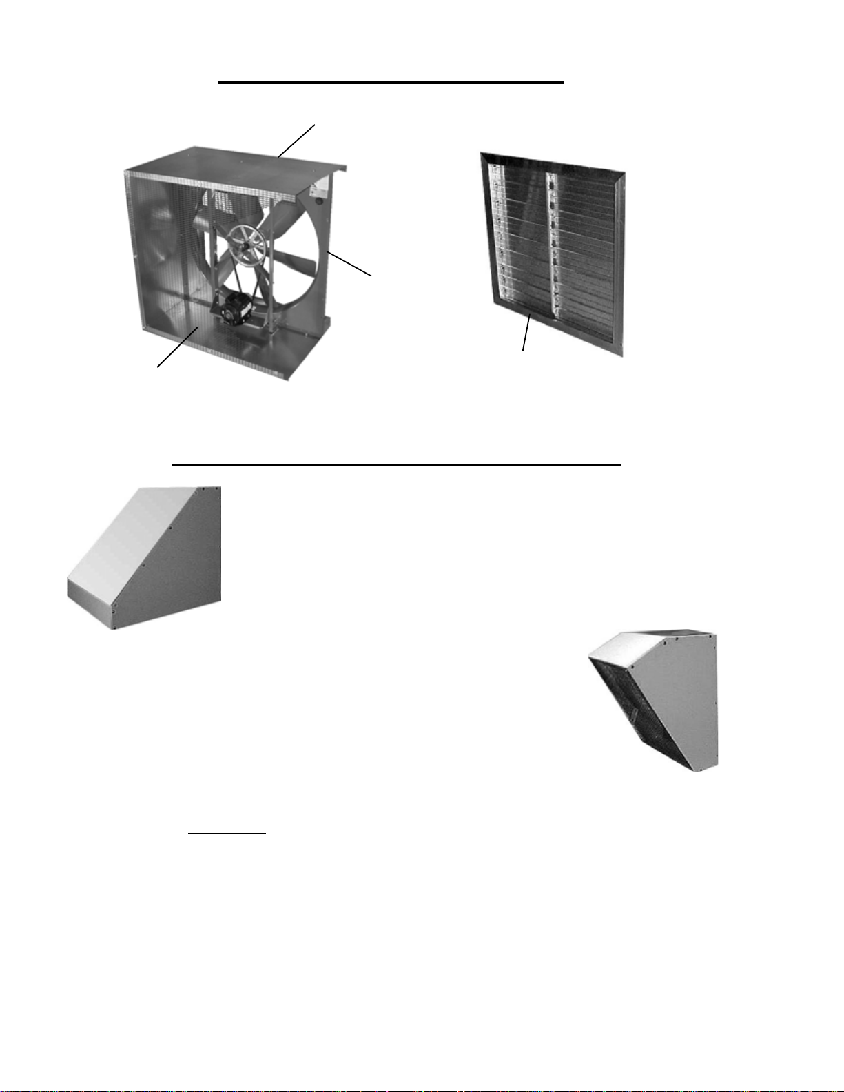
Standard MB Fan Package
Fan Housing
C-Fan
Shutter - (LRW shown - S/SR shutter used on
higher flow models)
Accessories for MB Fan Packages
INLET HOOD OPTION
• Specifically designed for supply applications
• Designed to prevent entrainment of moisture into the airstream
• Hardware kit included for ease of assembly
• PVC-coated wire guard available
• Wide range of sizes to fit every need
DISCHARGE HOOD OPTION
• Specifically desig ne d for e xha ust ap plic a tio ns
• Designed for all-weather performance with minimal pressure losses
• Hardware kit included for ease of ass embly
• PVC-coated wire guard available
• Wide range of sizes to fit every need
Spark-Resistant Construction
For hazardous locations, MBL and MBH fan packages
can be ordered with a non-ferrous blade assembly and
explosion proof motor. Motors only
Group D and Class II Groups F & G hazards.
qualify for Class I
Protective Coatings
For most applications, the American Coolair
thermosetting epoxy powder coating system will provide
the necessary surface protection for painted parts. For
applications that require more specialized surface
protection, American Coolair offers alternatives such as 6
mil epoxy coating or hot dip galvanizing. For more
information about special protective coatings, contact your
American Coolair representative.
Shutter Bird Guard
Guard made of PVC–coated steel wire with 1/2” x 1”
spacing protects shutter from damage by birds or
vandalism. Attaches flat against shutter face giving an
attractive appearance (requires Type S or SR shutter).
Mounting Flanges
Galvanized steel mounting flanges can be used for
mounting an inlet hood or a discharge hood to the wall.
They can also be used to mount the fan housing to the
wall if the fan housing is extending through the wall. A
hardware kit for installation is included.
6
Page 7
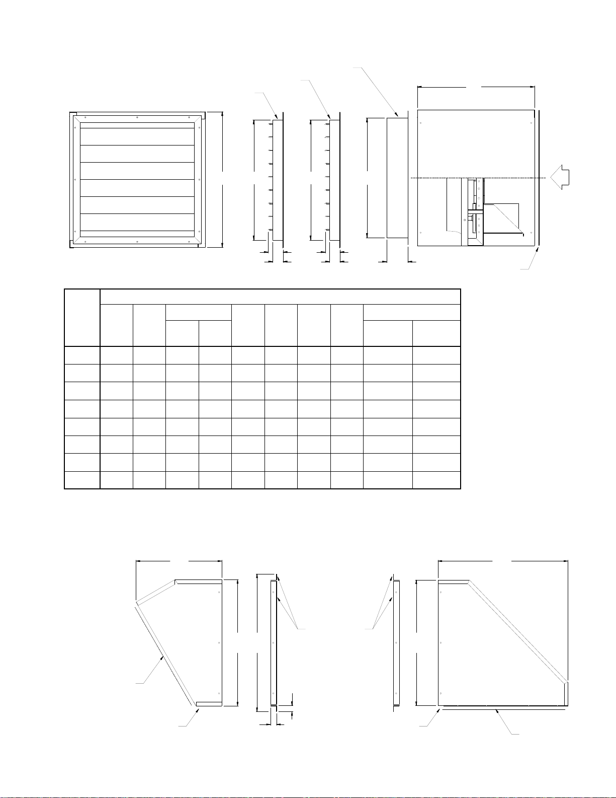
Type MB Fan Package and Accessory Dimensions
S/SR SHUTTER1
SU SHUTTER
LRW SHUTTER
1
1
B
A SQ.
C
C
C
AIRFLOW
Dimensions in inches
3 3/4
2 1/2
5 7/8
3
5
1
/2 x 1
PVC-COATED
WIRE GUARD
Dimension A is the OD of
the square wall housing,
including hardware.
3
Dimension B is the length of
the wall housing.
Dimension C is the OD of
the shutter frame.
Dimension D is the overall
Fan
Size
18, 20
24
Dimensions in Inches
1
A B
LRW
C
S/SR/
SU
D E F G
Square Wall Opening
Shutter
Clearance
2
Housing
Clearance
26 1/4 25 3/8 — 22 1/4 19 26 1/2 27 1/2 29 1/2 22 3/4 27
32 1/4 26 7/8 27 28 3/8 22 32 1/2 33 1/2 35 3/8 28 7/8 33
length of the discharge
38 1/4 26 7/8 33 34 3/8 24 5/8 38 1/2 39 1/2 41 3/8 34 7/8 39
30
44 1/4 32 5/8 39 40 3/8 27 5/8 44 1/2 45 1/2 47 3/8 40 7/8 45
36
50 1/4 32 5/8 45 46 3/8 30 1/4 50 1/2 51 1/2 53 3/8 46 7/8 51
42
56 3/8 32 5/8 51 52 3/8 32 7/8 56 1/2 57 1/2 59 1/2 52 7/8 57 1/8
48
62 3/8 32 5/8 57 58 3/8 35 3/4 62 1/2 63 1/2 65 5/8 58 7/8 63 1/8
54
68 3/8 32 5/8 — 64 3/8 35 3/4 68 1/2 69 1/2 71 5/8 64 7/8 69 1/8
60
1 - LRW shutter used on most models. S/SR shutter used on higher flow models. SU shutter used on all MBA models. See Pages 4 & 5 for shutter
usage by fan model.
2 - “Shutter Clearance” Wall Opening Dimension is for metal building installations only. Opening allows for shutter frame only to protrude to the outside.
3 - “Housing Clearance” Wall Op eni ng Dimension is f or i ns t a ll a ti ons where the MB pac k a g e is to be recessed into a wall.
hood.
Dimension E is the overall
height of both the discharge
and inlet hood.
Dimension F is the overall
length of the inlet hood.
Dimension G is the overall
height of the mounting
flanges.
Dimensions
in inches
1
/2 x 1, 16 GA.
PVC-COATED
WIRE GUARD
DISCHARGE HOOD
E G
1 5/8
1 5/8
MOUNTING
FLANGES
INLET HOOD
E
F D
1
/2 x 1, 16 GA.
PVC-COATED
WIRE GUARD
7
Page 8
Installation and Maintenance
Installation: Type MB fan packages are shipped
completely assembled with shutter, housing, fan and
guard for quick, easy installation. Installation and
maintenance instructions are included.
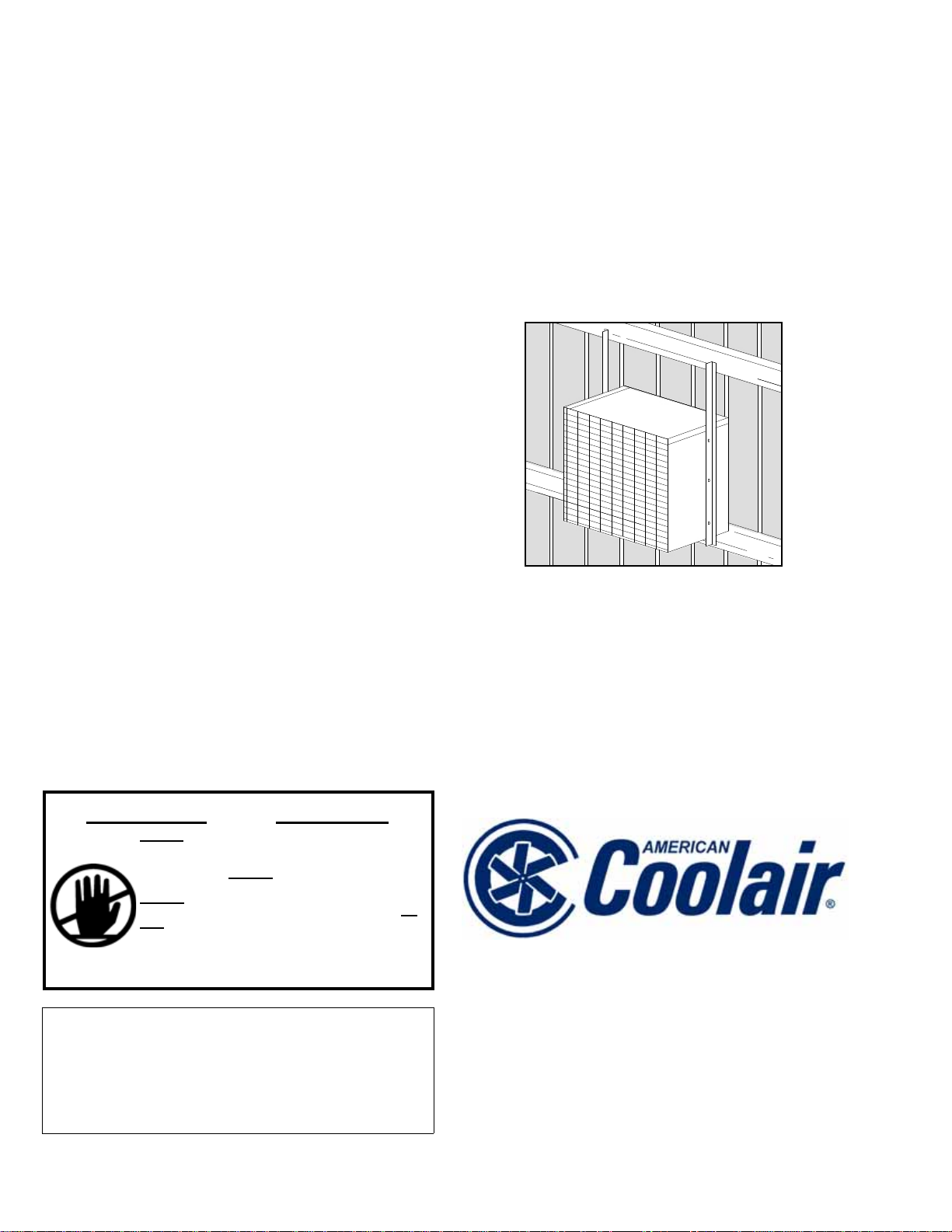
• Place the fan package on a supporting girt, on the
inside of the building, and push the fan package
against the outside skin.
• Cut an opening in the building panel slightly larger
than the shutter frame and smaller than the fan
housing (See dimensions on Page 7).
• Push the shutter through the opening.
• Attach two pieces of angle (supplied by others),
one on either side of the fan housing, from the
support girt to the girt above (See Figure 1).
• Fasten the fan housing to the angle with 6 selfdrilling, sheet metal screws (3 per side).
• Attach the building panel to the fan housing above
the shutter.
• Flash and caulk around the shutter opening to suit
the building panel.
• All electrical connections should be made by a
licensed electrician.
Maintenance: Type MB fan packages should be
cleaned as necessary to remove accumulated dust, dirt
and other foreign matter which may collect on blades
or other fan package parts.
Fan belt should be inspected and tension adjusted
after the first 8-10 hours of fan operation and
periodically thereafter. Check belt for proper
alignment.
Fan bearings are permanently lubricated. For
lubrication of electric motor, see instructions supplied
by the motor manufacturer.
Fig. 1
Limited Warranty
In the sale of its products, American Coolair Corporation agrees to correct, by repairs or replacement, any defects in workmanship or material that may develop
under proper and normal use during the period of one year from the date of shipment from the factory. Any product or part proving, upon American Coolair's
examination, to be defective during limited warranty period will be repaired or replaced, at American Coolair's option, f.o.b. factory, without charge.
Deterioration or wear caused by chemicals, abrasive action or excessive heat shall not constitute defects.
Motors are guaranteed only to the extent of the manufacturer’s warranty.
American Coolair's limited warranty does not apply to any of its products or parts that have been subject to accidental damage, misuse by the user, unauthorized
alterations, improper installation or electrical wiring, or lack of proper lubrication or other service requirements as established by American Coolair.
Repairs or replacements provided under the above terms shall constitute fulfillment of all American Coolair's obligations with respect to limited warranty.
THE LIMITED WARRANTY STATED HEREIN IS IN LIEU OF ALL OTHER WARRANTIES, EXPRESS, STATUTORY OR IMPLIED, INCLUDING WITHOUT
LIMITATION THAT OF MERCHANTABILITY AND FITNESS.
NO LIABILITY FOR RE INSTALLATION COST OR FOR A NY SPECIAL, INDIRECT OR CONS EQUENTIAL DAMAGES O F ANY NATURE IS ASSUMED OR
SHALL BE IMPOSED UPON AMERICAN COOLAIR.
WARNING CAUTION
DO NOT INSTALL FAN WITH MOVING PARTS WITHIN
8 FEET OF FLOOR OR GRADE LEVEL WITHOUT A
GUARD THAT COMPLIES WITH OSHA
REGULATIONS. DO NOT
WIRING COMPLIES WITH ALL APPLICABLE CODES.
DO NOT
SOURCE DISCONNECT AT THE FAN ITSELF. DO
NOT SERVICE EXCEPT BY A QUALIFIED
MAINTENANCE TECHNICIAN AND ONLY AFTER
DISCONNECTING THE POWER SOURCE. FAILURE
TO OBSERVE THESE PRECAUTIONS CAN RESULT
IN SERIOUS INJURY OR DEATH.
Represented By:
WIRE WITHOUT PROVIDING FOR A POWER
USE UNLESS ELECTRICAL
AMERICAN COOLAIR CORPORATION
PO BOX 2300, JACKSONVILLE, FL 32203
Phone: (904) 389-3646
Fax: (904) 387-3449
E-mail: [email protected]
Website: www.c oolair.com
Form No. 530-15-8 (August, 2011)
 Loading...