

Page 1

Drop-In Plancha
Installation Guide
Model Numbers
MPLD362CS-200, MPLD362CS-400,
MPLD362CR-200, MPLD362CR-400
MPLD Installation 13302_A USINTL
Page 2

Drop In Plancha Installation Guidelines
This document will provide guidelines for installing a drop-in Plancha. These
instructions apply to Cooktek model numbers: MPLD362CR-200, MPLD362CS-200,
MPLD362CR-400, and MPLD362CS-400.
The figures on the following pages show the necessary counter cut-outs and
maintenance access clearance. Read and understand thoroughly before attempting
installation.
For technical support, please call +1 (312) 274-9786 x 105.
The Plancha is comprised of a self-contained drop-in cooking module, plus two remote
control units (control knob and mode select button) which are connected via two 36”
(91.4 cm) long cables with push-in connectors. The power cord is hardwired in to the
unit and should be connected to a three phase supply (see spec. sheet for correct
voltage for each model number). The module is held securely in-place by a series of
studs (attached to unit) and nuts (provided). Once it is lowered into the required cutout, a bead of silicone or RTV should be used to completely seal the edge gaps to
prevent build-up of moisture and / or food debris under the rim. The counter should be
capable of supporting unit weight of 160lbs plus any applicable food load while using
the Plancha. The counter should be constructed out of stainless steel or suitably thick
stone so as to support the load.
The space directly in front and below the unit should be kept either open, or feature an
access panel at least 30” (76.2 cm) wide by 8” (20.3 cm) high centered on the unit for
maintenance access.
MPLD Installation 13302_A USINTL
Page 3
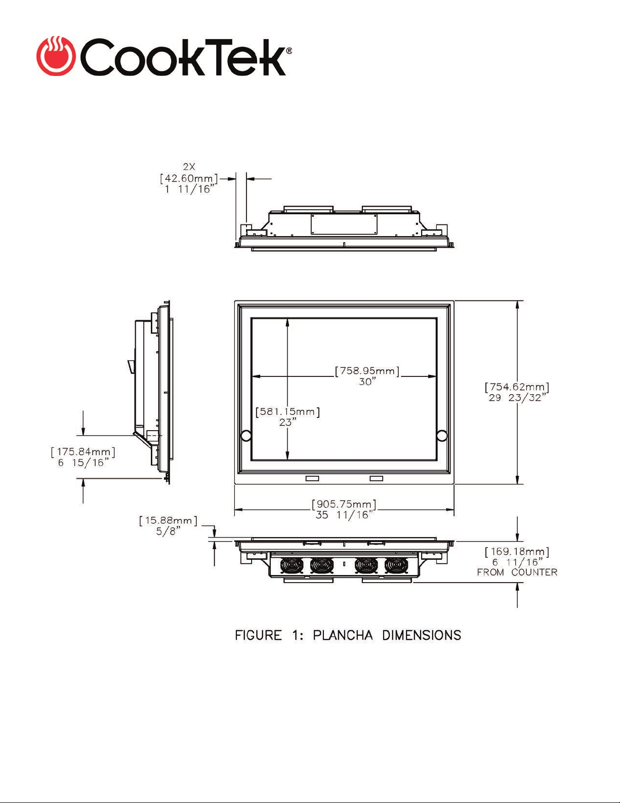
Figure 1 shows the overall general dimensions of the unit.
MPLD Installation 13302_A USINTL
Page 4

Figure 2 shows the required counter cut-out (essentially a large rectangle with two
smaller rectangular notches at the front edge).
MPLD Installation 13302_A USINTL
Page 5

Figure 3 shows the QTY 8 required Ø 5/16” (8 mm) holes for securing the unit to the
counter. The Plancha has #10-32 studs welded to the underside of the unit.
MPLD Installation 13302_A USINTL
Page 6

Figure 4 shows the required space below the bottom of the unit for maintenance. Front
access is also required for maintenance. Maintenance includes swinging the hinged
electronics base-plate away from the unit and disconnecting the control, display, power,
and litz cable. Once the cables are disconnected the base-plate can be removed.
MPLD Installation 13302_A USINTL
Page 7

Figure 5 shows the required cut-out for the grease drawers. Two drawers are installed
on either side of the unit and slide on qty 2 Ø0.375” x 26.75” long rods (included). The
back panel of the cabinet should have qty 2 holes matching those on the front
coincident vertical and horizontal placement. The rods are installed with qty 2 (per rod)
8-32 countersink screws (included). The specific location of the cut-out is shown with
respect to the center of the unit and the top of the counter.
MPLD Installation 13302_A USINTL
Page 8

Figure 6 shows a cut-away view of the grease drawers and installed rods.
MPLD Installation 13302_A USINTL
Page 9

Figure 7 shows the mode button and control knob cut-out. The cut-out is required
below both of the displays on the Plancha unit.
MPLD Installation 13302_A USINTL
Page 10

Figure 8 depicts a typical cross section for a flush mounted unit. An offset is formed
into the counter to allow for the 0.075” thick metal and a bead of silicone caulk to glue
the unit down. A bead of silicon should also fill the gap between the Plancha flange and
the vertical surface of the offset.
DO NOT WELD THE UNIT INTO PLACE AS
THIS CAN DAMAGE THE ELECTRONICS OF
THE UNIT AND WILL VOID THE WARRANTY
MPLD Installation 13302_A USINTL
.
 Loading...