

Page 1

INSTALLATION & MAINTENANCE COOKSON FIREGARD™ CHAIN & ES 10-343
ECO #1515
REVISION #
0000
FIREGARD™ CRANK OPERATORS
BY:
RICKM
DATE:
3/23/2011
03/11
INSTRUCTION MANUAL
FireGard™ Chain Operator
(Model FCF)
&
FireGard™ Crank Operator
(Model FKF)
F-SR Rev.01
Page 2

FireGard™ Chain and Crank
1
WARNING
1. CAUTION: Review all installation instructions, procedures, cautions and warnings contained
within this manual prior t o installing and/or servicing this product. Maximum fire protection is
provided when installed in accordance with factory specifications with provided fuse link
systems.
2. Installation and testing to factory specifications shall be performed by factory authorized
personnel for proper operation in accordance with all of the latest National Fire Protection
Association (NFPA), Underwriters Laboratories (UL), National Electrical Code (NEC), local,
state, county, district and/or other applicable building and fire standards, guidelines,
regulations and codes including, but not limited to, all appendices and amendments and the
requirements of the local Authority Having Jurisdiction (AHJ).
3. Installation to be performed by factory authorized door system technicians only.
4. Clear fire door opening and prohibit all traffic through door opening during system testing!
INTRODUCTION
The closing system is designed to be used in conjunction with a temperature activated fusible
link arrangement. It is designed for use on rolling fire doors and counter fire doors. Optionally,
the unit is designed to accept a bolt-on, fail-safe floor level reset or automatic reset release device
for connection to local detectors or a central alarm system.
Page 3

FireGard™ Chain and Crank
2
IMPORTANT MECHANICAL INSTALLATION PROCEDURE
WARNING - To reduce the risk of severe injury or death:
1. READ AND FOLLOW ALL INSTALLATION INSTRUCTIONS.
2. Spring tension must be adjusted to allow the fire door to self close during a drop t est. A door
that is operating improperly could cause severe injury. Have qualified door system technicians
make repairs to spring assemblies and other hardware before installing the operator.
3. Cover any exposed, moving operator parts that are less than 8 feet above the floor.
4. When utilized, locate the “push to close” control station: (a) within sight of the door, (b) at a
minimum height of 5 feet so small children cannot reach it, and (c) away from all moving parts
of the door.
5. Instruct the end user on proper operation of the operator.
6. The door is under extreme spring tension. Have qualified door system technicians make all
necessary adjustments and repairs to the door.
7. When utilized, read and understand the wiring diagram of the alarm release device box.
8. For products having a manual rel ease, instruct the end user on the operation of the manual
release.
Page 4
FireGard™ Chain and Crank
3
INSTALLATION INSTRUCTIONS
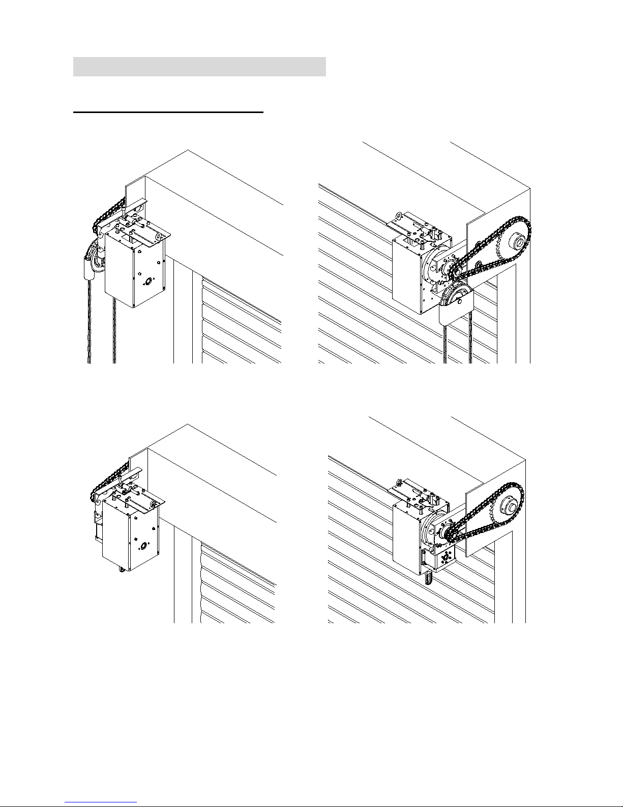
INSTALLATION POSITIONS
RH
LH
(Installation Illustration for FCF)
RH
LH
(Installation Illustration for FKF)
Consult factory for changes in installation positions.
Page 5
FireGard™ Chain and Crank
4
OPERATOR MOUNTING
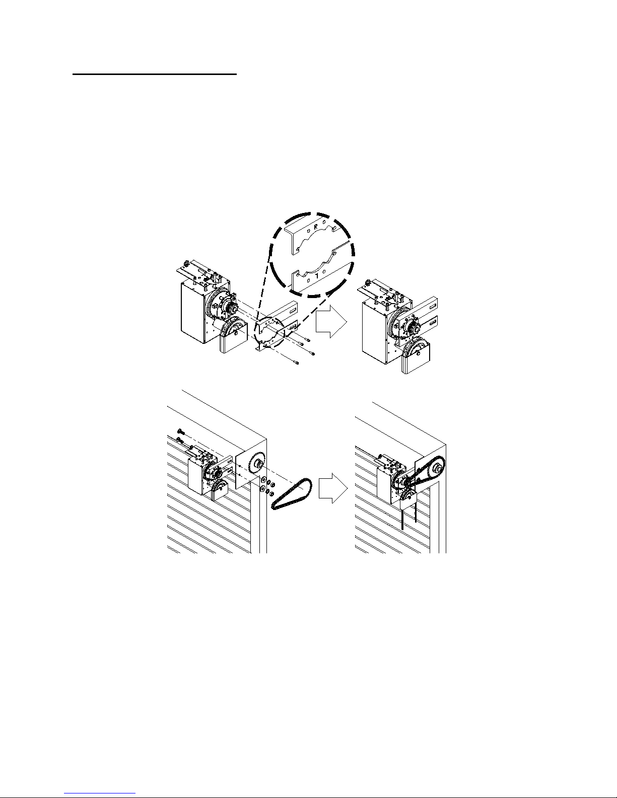
1. Before the operator is installed, verify that the door is properly operating and balanced.
2. Make sure the mounting plates are correctly positioned for RH or LH mounting.
3. Attach and tighten the mounting hardware to the mounting plate.
4. Tighten the operator mounting plate to the door.
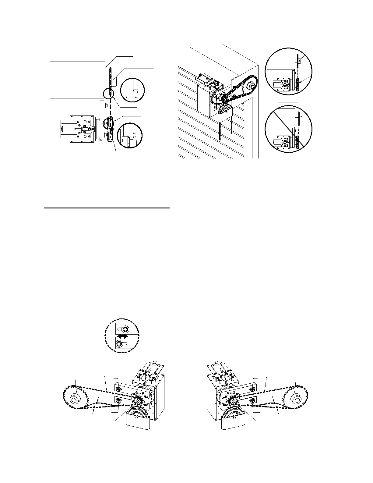
5. When the operator is mounted on the bracket, be sure the door sprocket is properly aligned / in
the same plane with the operator drive sprocket before securing to the shaft.
6. The shelf or bracket must provide adequate support for the operator. Prevent play betwe en
operator and door shaft. Permit operator to be fastened securely and with the drive shaft parallel
to the door shaft.
Page 6
FireGard™ Chain and Crank
5
Bracket
Door Sprocket
View "B"
B
View "B"
View "A"
View "A"
A
Drive Sprocket
Door
Sprocket
Operator
Drive
Sprocket
Correct
Incorrect
* Chain hoist shown. Hand crank similar.
ADJUSTING THE DRIVE CHAIN
NOTE: Use correct type, size and proper length of roller chain.
1. Adjust the drive chain by tilting or move the operator so that there is about 1/4” of slack when
the chain is depressed.
2. Once the drive chain has been tightened, then tighten the operator mounting screws.
LH
S1 . S2
Drive Chain
Door Sprocket
Drive Sprocket
1/4"
Drive Chain
Door Sprocket
Drive Sprocket
1/4"
RH
S1
S2
S1
S2
Page 7
FireGard™ Chain and Crank
6
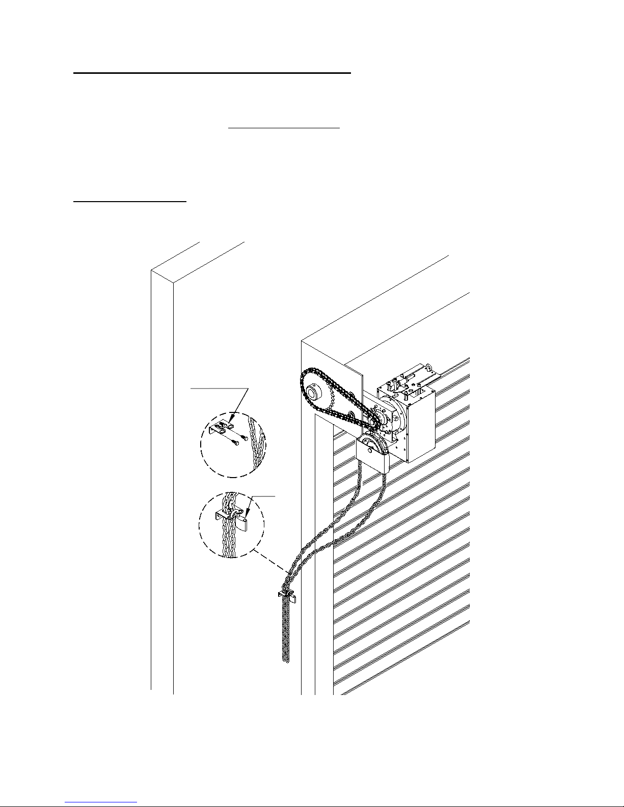
ADJUSTING OPERATING CHAIN LENGTH (FCF units only)
Operating chain is provided in a standard length. Depending on door height, the chain may need to
be shortened or lengthened. A DIFFERENT COLOR connecting link ca n be found in the hand
chain. Use this link for breaking the chain to make adjustments to the hand chain length so that the
bottom of the hanging chain is 2’ to 3’ above the floor.
CHAIN HOLDER
Install at a convenient location.
Optional
Chain Holder
Page 8

FireGard™ Chain and Crank
7
IMPORTANT SAFETY INSTRUCTIONS
WARNING – To reduce the risk of severe injury or death:
1. READ AND FOLLOW ALL INSTRUCTIONS.
2. Never let children operate or play with door controls.
3. Personnel should keep away from a door in motion and keep the moving door in sight until it is
completely closed or opened. NO ONE SHOULD CROSS THE PATH OF A MOVING
DOOR.
4. KEEP DOORS PROPERLY OPERATING AND BALANCED. See Door Manufacturer’s
Owner’s Manual. An improperly operating or balanced door could cause severe injury or death.
Have trained door systems technician make repairs to cables, spring assemblies, and other
hardware.
5. SAVE THESE INSTRUCTIONS.
OPERATING INSTRUCTIONS
FCF – Pull operating chain to open and close door. To stop door, let go of the chain.
FKF – Turn crank to open and close door. To stop door, stop turning.
Page 9
FireGard™ Chain and Crank
8
FUSIBLE LINK CONNECTION
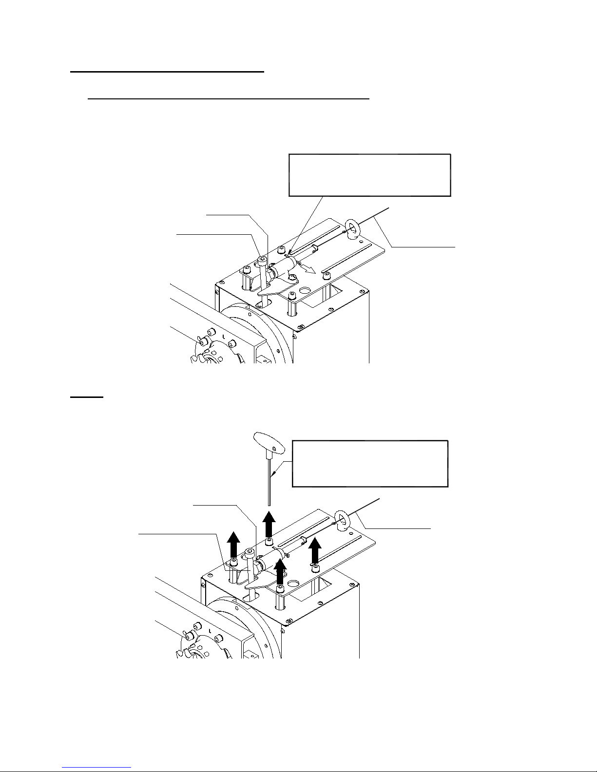
REMOVE COTTER PIN FROM RELEASE ASSEMBLY.
Consult NFPA-80 and the authority having jurisdiction for fusible link location(s) and method.
Remove cotter pin after
connection of fusible link.
RELEASE LEVER
PLUNGER
FUSIBLE LINK
NOTE: Fusible link release can be substituted by an alarm release box. Fusible link release can be
removed by loosening 4 screws. Alarm release can be attached by using the same 4 screws.
RELEASE LEVER
PLUNGER
Screws to loosen and
tighten releases.
FUSIBLE LINK
Page 10
FireGard™ Chain and Crank
9
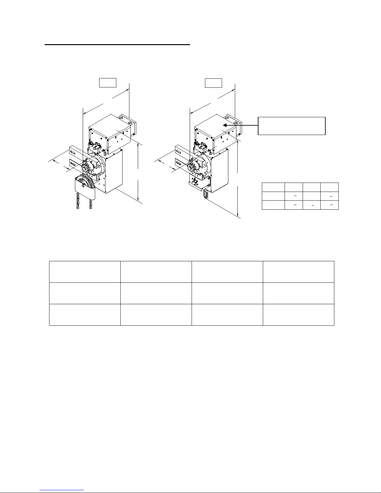
OPTIONAL ALARM RELEASE BOX
(Inch)
FKF
FCF
BA C
16
10
1
2
16
3
4
FCF
A
C
B
FKF
A
C
B
10
1
2
15
3
4
20
1
4
Alarm Release Box Type:
Model Reset Method Input Voltage Alarm Input
AR-A2 Manual 115VAC Dry Contact Open
AR-C Auto Reset 115VAC Dry Contact Open
Alarm release box
Page 11
FireGard™ Chain and Crank
10
MAINTENANCE INSTRUCTIONS
The brake is a self-adjusting brake. It is maintenance free. The brake assembly requires no
additional adjustment during its lifetime.
If optional alarm release box is used, then disconnect alarm powe r supply
to the alarm release box before servicing.
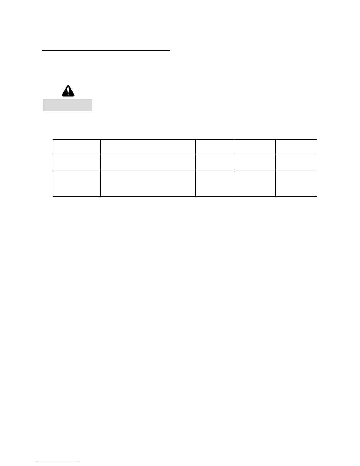
Check the following items at the intervals listed:
CHECK LIST DESCRIPTION
EVERY
3 MONTHS
EVERY
6 MONTHS
EVERY
12 MONTHS
Fasteners Check & tighten as required
●
Drop-test
Inspect door, drop-
test for proper
operation and full closure per
NFPA-80
●
Inspect and service whenever a malfunction is observed or suspected.
Before servicing, always disconnect power supply to the alarm release box, if provided.
All replacement parts must be obtained from the door manufacturer per NFPA 80.
Testing of the FCF and FKF are independent of, and shall in no way be interpreted as an alternative
method of testing the fire alarm system, and/or any other system component employed on the fire
door or counter fire door installation. TESTING SHALL BE PERFORMED AND WITHNESSED
FOR PROPER OPERATION.
WARNING
 Loading...