

Page 1

INSTALLATION & MAINTENANCE COOKSON M100 FIREGARD
TM
ECO # 1515 REVISION # 0001
M100 FIREGARD
TM
CRANK OPERATORS
BY: RICKM DATE: 2/9/2011
02/11
AUTO-RESET MANUAL OPERATOR
M100 FireGardTM Chain (Model FCA)
&
M100 FireGardTM Crank (Model FKA)
INSTRUCTION MANUAL
F-AR Rev.02
Page 2

WARNING
1. CAUTION: Review all installation instructions, procedures, cautions and warnings contained within
this manual prior to installing and/or servicing this product. As with all releasing device systems,
maximum fire protection is provided when installed in accordance with factory specifications and
used with optional fuse link systems.
2. Installation and testing to factory specifications shall be performed by factory authorized personnel
for proper operation in accordance with all of the latest National Fire Protection Association (NFPA),
Underwriters Laboratories (UL), National Electrical Code (NEC), local, state, county, district and/or
other applicable building and fire standards, guidelines, regulations and codes including, but not
limited to, all appendices and amendments and the requirements of the local Authority Having
Jurisdiction (AHJ).
3. Installation to be performed by factory authorized door system technicians only.
4. Clear fire door opening and prohibit all traffic through door opening during system testing!
INTRODUCTION
The releasing device is a failsafe constantly energized solenoid mechanism. It is designed for use on
rolling fire doors and counter fire doors. Inside the mechanism, contact relays receive the alarm signal
from the fire alarm control panel. When the unit receives the signal, the power to the solenoid is cut,
releasing the fire door mechanism and hence closing the fire door. The alarm signal can be Form C dry
contact or 24VDC/VAC. A power interruption in excess of 10 seconds will release the solenoid
mechanism. The release has a 10 second delay on alarm, closed door detection capabilities, Form C
relay outputs for the status of release box and 24VDC power output for door close warning.
1
M100 FireGardTM Chain & Crank
02/11
Page 3
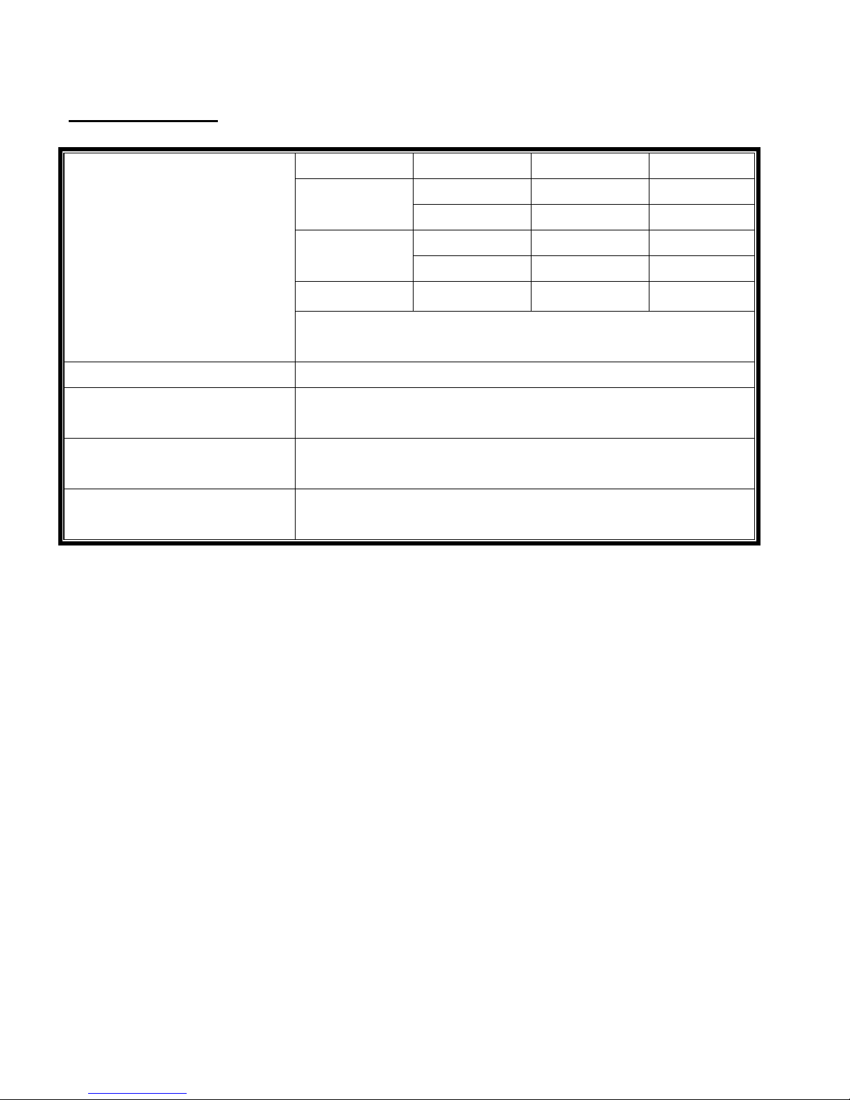
SPECIFICATION
Input Power:
Not Supervised
Alarm Dry Contact Rating: 24VDC, 0.5A, Not Supervised
Alarm Door Close Warning:
Brake Release (Dry Contact):
Fuse: F1: 3A@250V, Slo-Blo Type
Voltage Frequency Standby Alarm*
50 Hz 0.3A 0.4A
120VAC
60 Hz 0.3A 0.4A
50 Hz 1.5A 1.8A
24VAC
60 Hz 1.5A 1.8A
24VDC - 0.6A 1.2A
*Note: Amp value is during alarm condition with 1A load warning
connected.
24VDC @Max. 1A, Resistive, Special Application (see below),
Common, Not Supervised
Rating: 24VAC/VDC, 2A Max., Resistive Load, Common,
Not Supervised
F2: 1A@250V, Fast-Act Type
z 24V input power can be 24VDC or 24VAC or 24VDC from an approved UL1481 regulated power
supply.
z 18-gauge wire recommended.
z For “Indoor Dry” location use only.
z Close warning power is provided for less than a minute. Any UL Listed audible or visual device
may be used if the 24VDC input is powered by a UL1481 regulated and power limited power
supply.
z Optional: Activation/connection of UL approved fusible links.
2
M100 FireGardTM Chain & Crank
02/11
Page 4

IMPORTANT MECHANICAL INSTALLATION PROCEDURE
WARNING - To reduce the risk of severe injury or death:
1. READ AND FOLLOW ALL INSTALLATION INSTRUCTIONS.
2. Spring tension must be adjusted to allow the fire door to self close during a drop test, alarm
activation and/or power failure. A door that is operating improperly could cause severe injury. Have
qualified door system technicians make repairs to spring assemblies and other hardware before
installing the operator.
3. Cover any exposed, moving operator parts that are less than 8 feet above the floor.
4. Do not connect the door operator to the source of power until instructed to do so.
5. When utilized, locate the “close” control station: (a) within sight of the door, (b) at a minimum
height of 5 feet so small children cannot reach it, and (c) away from all moving parts of the door.
6. Instruct the end user on operation of the operator / release device.
7. The door is under extreme spring tension. Have qualified door system technicians make all
necessary adjustments and repairs to the door.
8. Make sure the available alarm power supply to be connected to the operator is of the same voltage,
frequency, phase and wattage as indicated on the nameplate of the alarm box.
9. Read and understand the wiring diagram of the alarm box (if applicable), and any other equipment to
be connected to the operator.
10. Always disconnect power whenever installing or servicing the door or operator.
3
M100 FireGardTM Chain & Crank
02/11
Page 5
INSTALLATION INSTRUCTIONS
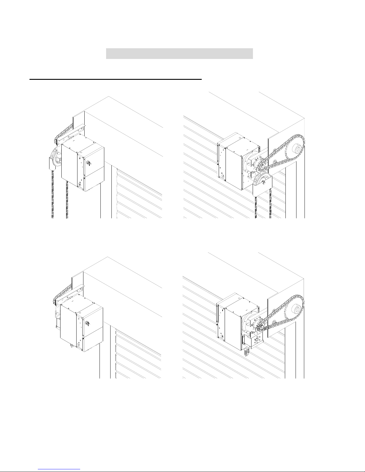
INSTALLATION POSITIONS FOR FCA & FKA
LH
(Installation Illustration for FCA)
LH
RH
RH
Consult factory for changes in installation positions.
(Installation Illustration for FKA)
4
M100 FireGardTM Chain & Crank
02/11
Page 6
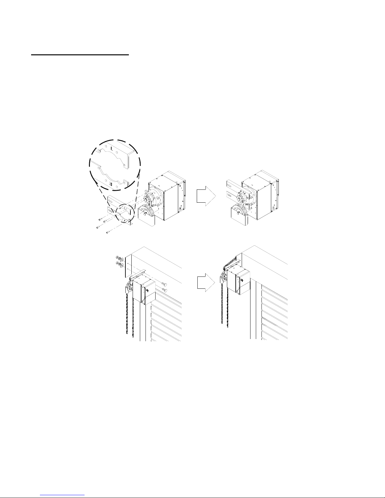
OPERATOR MOUNTING
1. Before the operator is installed, ve rify that the door is properly operating and balanced.
2. Make sure the mounting plates are correctly positioned for RH or LH mounting.
3. Attach and tighten the mounting hardware to the mounting plate.
4. Tighten the operator mounting plate to the door.
5. When the operator is mounted on the bracket, be sure the door sprocket is properly aligned / in the
same plane with the operator drive sprocket before securing to the shaft.
6. The shelf or bracket must provide adequate support for the operator. Prevent play between operator
and door shaft. Permit operator to be fastened securely and with the drive shaft parallel to the door
shaft.
5
M100 FireGardTM Chain & Crank
02/11
Page 7
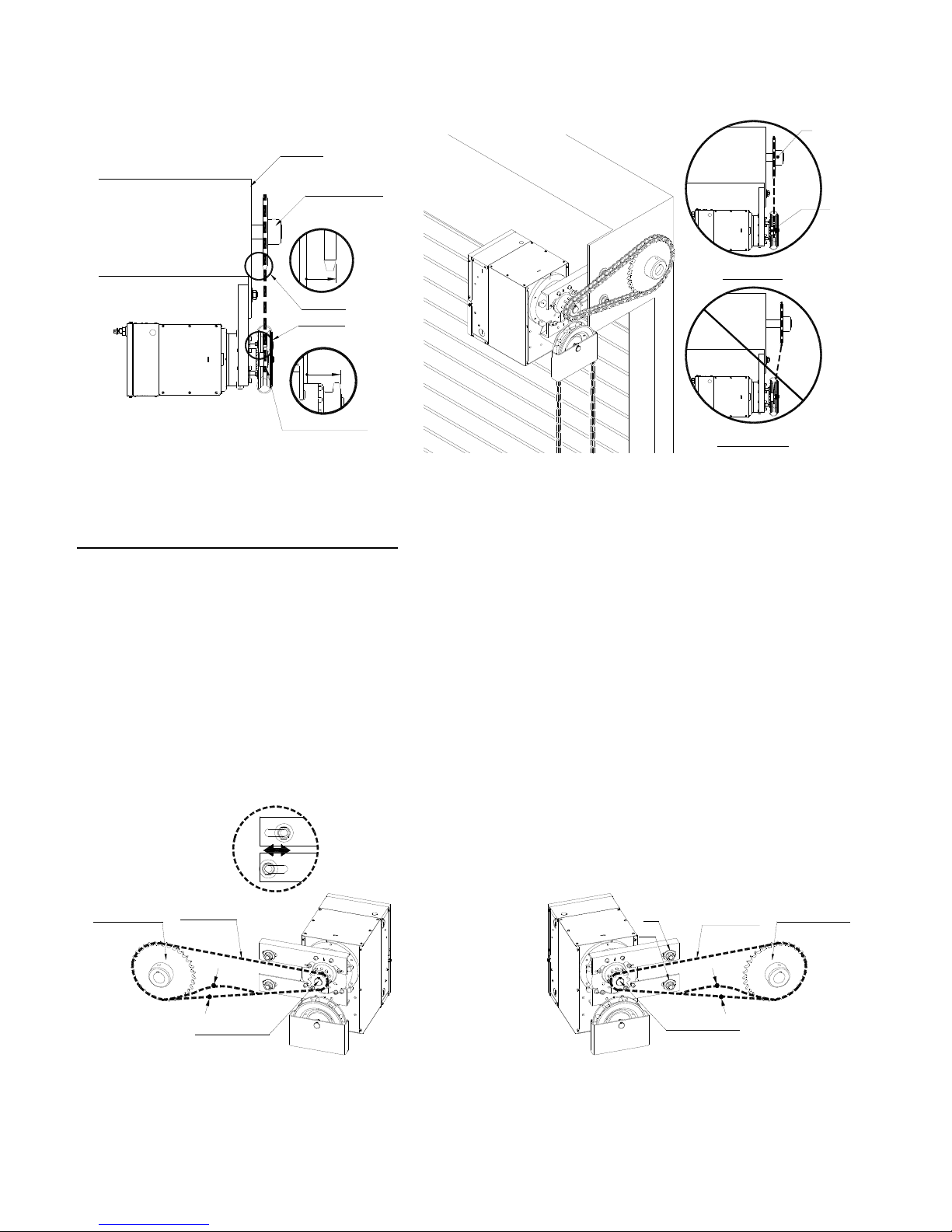
Bracket
Door
Sprocket
Door Sprocket
View "B"
B
View "B"
View "A"
View "A"
Correct
Operator
Output
Sprocket
A
Drive Sprocket
Incorrect
* Chain hoist shown. Hand crank similar.
ADJUSTING THE DRIVE CHAIN
NOTE: Use correct type, size and proper length of roller chain.
1. Adjust the drive chain by moving the mounting screws so that there is about 1/4” of slack when the
chain is depressed.
2. Once the drive chain has been tightened, then tighten the operator mounting screws.
Door Sprocket
Drive Chain
1/4"
Drive Sprocket
LH
S1 . S2
RH
S1
S2
Drive Chain
1/4"
Drive Sprocket
6
M100 FireGardTM Chain & Crank
Door Sprocket
02/11
Page 8
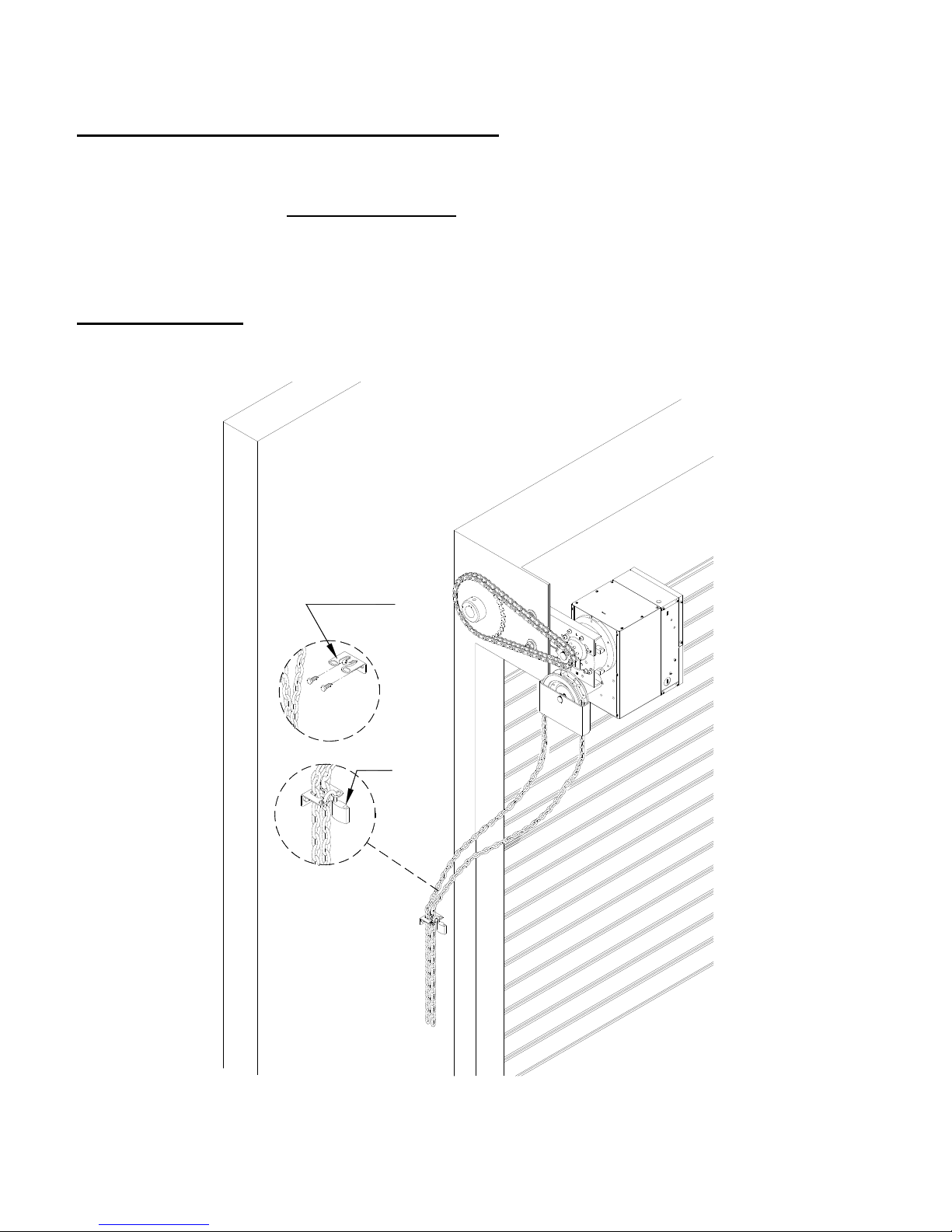
ADJUSTING OPERATING CHAIN LENGTH (FCA units only)
Operating chain is provided in a standard length. Depending on door height, the chain may need to be
shortened or lengthened. A DIFFERENT COLOR connecting link can be found in the hand chain. Use
this link for breaking the chain to make adjustments to the hand chain length so that the bottom of the
hanging chain is 2’ to 3’ above the floor.
CHAIN HOLDER
Install at a convenient location.
Chain Holder
Optional
7
M100 FireGardTM Chain & Crank
02/11
Page 9
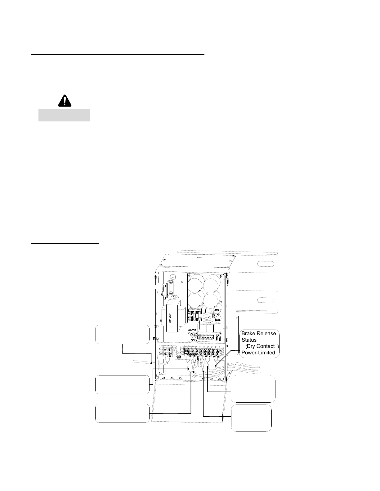
FIRE ALARM CONNECTION INSTRUCTION
- For “Indoor Dry” location use only. All wiring must satisfy the most current version of
NFPA72 – National Fire Alarm Code and the National Electric Code.
- 18-gauge wire is recommended.
Disconnect power supply before servicing.
WARNING
1. ELECTRICAL CONNECTIONS
Installation of all wiring and connections shall be performed in accordance with, but not limited to,
the latest NFPA, U.L. and N.E.C. standards. In addition, all installations subject to Canadian
standards shall be performed in accordance with the Canadian Electrical Code, Part I, with respect
to wiring material, wiring gauge related to power capacity requirements and circuit length and
wiring methods.
2. Verify voltage rating of release device to power source being utilized.
3. Connect power and alarm connection to the unit.
WIRE ROUTING
115VAC Input Power
Non-power Limited
Input 24VAC/VDC
Non-power Limited
Dry Contact Alarm
Power-Limited
sw
Brake Release
Statu
s
L
1
L
2
1
2
3
4
5
6
7
8
9
Dry Contact
︵
Power-Limited
Alarm Door Close
Warning, 24VDC
Power-Limited,
Supervised
Close Button
(Dry Contact)
(N/C)
Power-Limited
︶
8
M100 FireGardTM Chain & Crank
02/11
Page 10
9
M100 FireGardTM Chain & Crank
02/11
TERMINAL CONNECTIONS
Disconnect power supply before servicing.
TB1
L1 L2
Input power 115VAC*, Not Supervised See Note. 4
TB2
1 (+) 2 (-)
3 4*
5 6 7
8 9
Input 24VDC/VAC
Use Power Limited source
only
Not Supervised
*Note. 4
Alarm Dry Contact (N/C)
Not Supervised *Note 1
Alarm door close warning
24VDC, total 1A
Common, Not Supervised
*Note 2
Brake release status
(Dry contact)
24VAC/VDC, 2A Max.
Resistive load, Common,
Not Supervised
*Note 3
Close button
Dry contact (N/C)
*Note:
1. Terminal 3&4
Building fire alarm panel (FACP) needs to provide dry contact (N/C) connection with minimum capacity of 24VDC and 0.5 amp.
Terminal 4
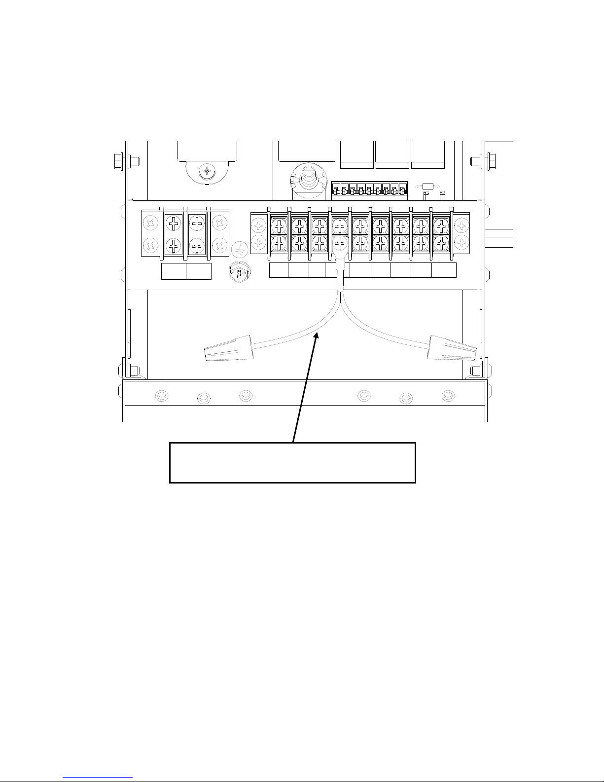
When connecting more than one wire/connector to the terminal, must use enclosed Part # CDA-FH600-WHF02. See page 13 for
illustration.
2. Terminal 6&7
This connection provides 24VDC, 1A power with 18AWG wire for maximum of 20 ft. Upon alarm signal, this connection can be
used to provide power for warning devices. The warning power is provided for less than a minute. The wiring connections are
enclosed within conduit or equivalently protected against mechanical injury.
3. Terminal 8&9
These terminal connections will provide the status of this release device. When release device is in the standby mode, connection is
open (N/O). When release device have been activated or released, connection would be in closed (N/C) state.
4. See connection chart for power inputs. A regulated, power limited UL1481 Power Supply must be used for this terminal.
WARNING
Page 11

10
M100 FireGardTM Chain & Crank
02/11
Connection Chart
Terminals
Connection
Type
Line In
High Voltage
L1 & L2
Low Voltage
1 & 2
(24VDC or 24VAC)
Alarm Connection
3 & 4
Power Input
Connect
115VAC
Connect
24VDC or 24VAC
(Voltage supplied by FACP
or an UL listed power supply)
Connect FACP*
Alarm Dry Contact
High Voltage Alarm Signal
Connect Alarm Signal
115VAC
Do Not Connect
Jump
(Wire size min 18AWG)
Low Voltage Alarm Signal Do Not Connect
Connect Alarm Signal
24VDC or 24VAC
(Voltage supplied by FACP)
Jump
(Wire size min 18AWG)
*Note: FACP – Fire Alarm Control Panel.
Page 12
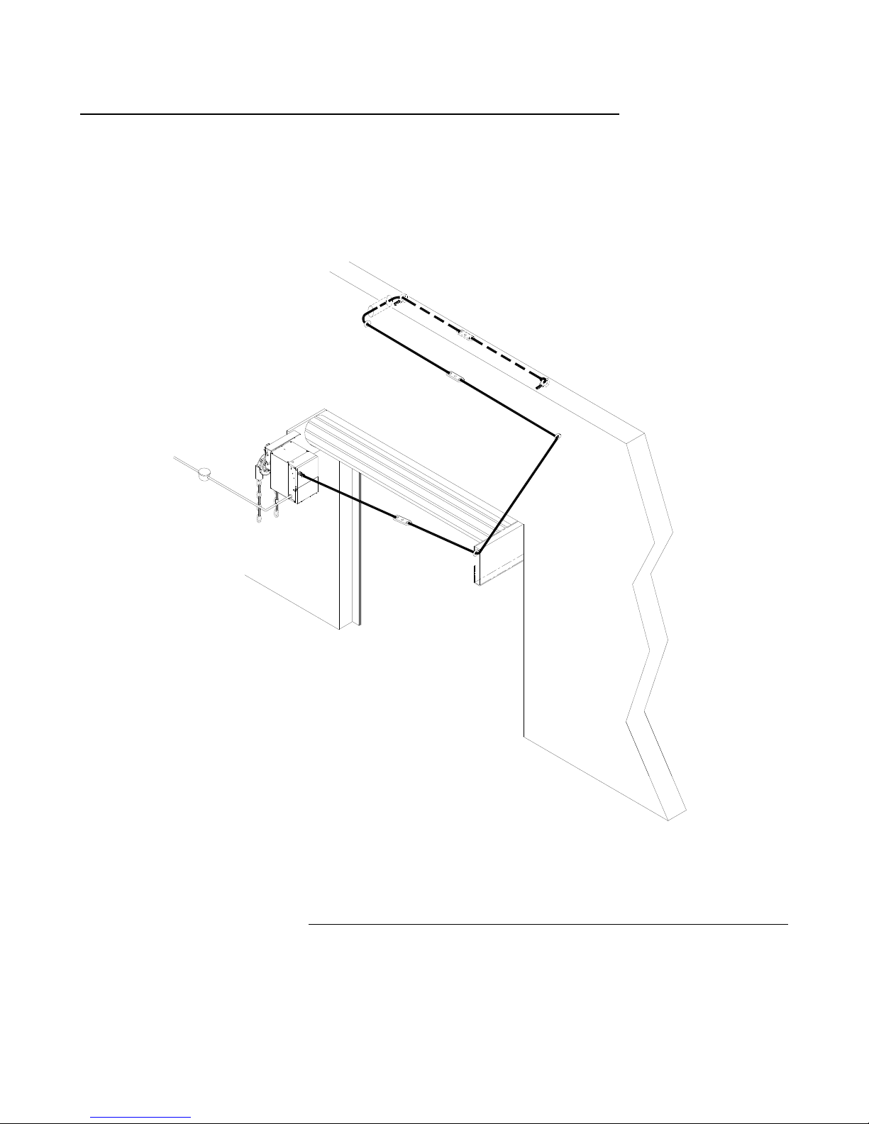
OPTIONAL FUSIBLE LINK CONFIGURATION/REFERENCE
1. Actual configuration may differ. Must pull cable straight a minimum of 18 inches before
changing direction. See door manufacturer recommendations and NFPA 80 for recommended
fuselink configurations.
2. To be performed by qualified door system technicians only.
FCA
Thru wall conduit
Eyebolt
Eyebolt
Fuse Link
Ceiling
Fuse Link
Eyebolt
Fuse Link
Eyebolt
Eyebolt
3. Optional fuselink arrangement hardware [sash chain or cable, eyebolts, fuselinks, turnbuckles] shall
be installed as per door manufacturer’s recommendations (figure 1 represents a typical installation
configuration). Note that the initial direction of pull is horizontal coming of off the door operator.
An eyebolt installed at a distance of 18 to 24 inches from the operator should adequately redirect
sash chain.
Figure 1
11
M100 FireGardTM Chain & Crank
02/11
Page 13
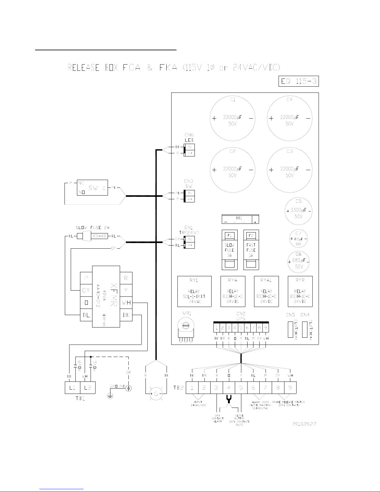
WIRING DIAGRAM ILLUSTRATION
12
M100 FireGardTM Chain & Crank
02/11
Page 14
(
)
5
6
L
1
L
2
1
2
3
4
7
8
9
Must use when having two connections.
P/N:CDA-FH600-WHF02
13
M100 FireGardTM Chain & Crank
02/11
Page 15
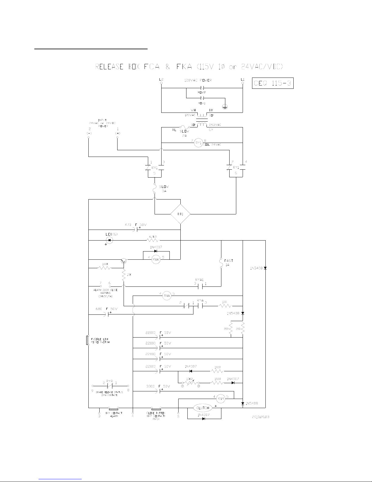
SCHEMATIC ILLUSTRATION
£g
~
~
+
£g
£g
£g
£g
£g
£g
14
M100 FireGardTM Chain & Crank
02/11
Page 16
TESTING
1. Simulate an alarm condition and see if the solenoid disengages and releases the fire door.
2. Simulate a power failure and see if the solenoid disengages and releases the fire door.
RESETTING
1. Make sure power and alarm connection is normal.
2. Operate chain or crank to open the door to the fully open position.
Note: If the power or the alarm is not normal, chain or crank operation will slip and not open the door.
MAINTENANCE INSTRUCTIONS
Disconnect power supply before servicing.
WARNING
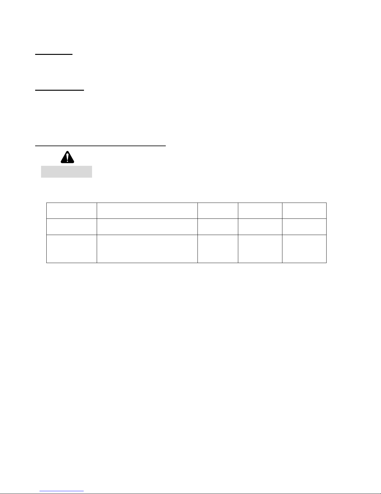
Check the following items at the intervals listed:
CHECK LIST DESCRIPTION
Fasteners Check & tighten as required
Drop-test
Inspect and service whenever a malfunction to either the door or release device is observed or
Before servicing, always disconnect power supply to the release device.
Replace fuses only with those of the same type and rating.
Inspect door, drop-test for
proper operation and full closure
per NFPA-80
suspected.
EVERY
3 MONTHS
EVERY
6 MONTHS
●
EVERY
12 MONTHS
●
All replacement parts must be obtained from the door manufacturer per NFPA 80.
Testing of the FCA and FKA are independent of, and shall in no way be interpreted as an alternative
method of testing the fire alarm system, and/or any other system component employed on the fire door
or counter fire door installation. TESTING SHALL BE PERFORMED AND WITHNESSED FOR
PROPER OPERATION.
15
M100 FireGardTM Chain & Crank
02/11
 Loading...