

Page 1
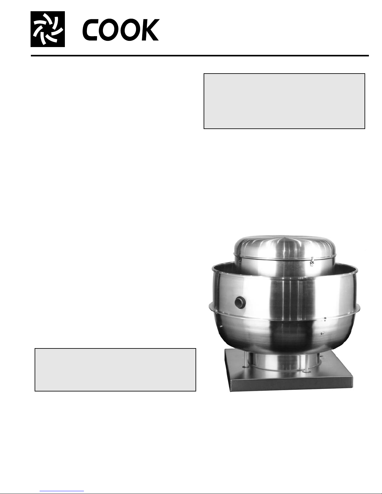
VCR
Centrifugal Roof and Wall Exhausters
INSTALLATION, OPERATION, AND MAINTENANCE MANUAL
This publication contains the installation, operation
and maintenance procedures for standard units of the
VCR/VCRD/VCR-HP/VCRD-HP/VCR-XP/VCRD-XP Centrifugal Roof and Wall Exhausters. Carefully read
this publication prior to installation or maintenance
procedure.
Loren Cook catalog, VCR, provides additional information describing the equipment, fan performance, available
accessories and specification data.
For additional safety information, refer to AMCA publication 410-96, Safety Practices for Users and Installers of
Industrial and Commercial Fans.
All of the publications listed above can be obtained from
Loren Cook Company by phoning (417)869-6474, extension 166; by FAX at (417)832-9431; or by e-mail at
info@lorencook.com.
For information and instructions on special equipment,
contact Loren Cook Company at (417)869-6474.
Receiving and Inspection
Immediately upon receipt of a VCR fan, carefully inspect
the fan and accessories for damage and shortage.
• Turn the wheel by hand to ensure it turns freely and
does not bind.
• Record on the Delivery
Receipt any visible sign of
damage.
Handling
Lift the fan by the lifting lugs
provided under top cap. Never lift
by the shaft, motor or housing.
1-1/16 inch diameter drain hole should be inserted on the
bottom side of the unit for drainage.
Personal Safety
Disconnect switches are recommende d. Place
the disconnect switch near the fan in order that
the power can be swiftly cut off in case of an
emergency, and in order that maintenance personnel are provided complete control of the
power source.
Fan Installation
a. Ensure the fan discharge is a minimum 40 inches
above the roof surface and a minimum of 10 foot from
any building air intake in order to comply with NFP A 96.
b. Minimum exhaust velocity in the duct should be 1500
FPM in accordance with NFPA 96.
c. If the fan is installed on a surface that is not level, install
the fan in a position that places the drain tube at the
lowest position.
d. Secure the fan to the roof curb at all four corners using
a minimum of four anchor bolts, lag screws or other
suitable fastener.
Storage
If the fan is stored for any
length of time prior to installation,
store it in its original shipping
crate and protect it from dust,
debris and the weather.
WARNING
This fan has rotating parts. Safety precautions
should be exercised at all times during installation,
operation, and maintenance.
ALWAYS disconnect power prior to working on fan.
Lifting Lugs
Installation
If the fan was delivered with the motor un m ou n ted , se e
the maintenance sections for belt and pulley installation.
If the fan was purchased as a wall mount unit and a
grease terminator or grease trough was not purchased, a
VCR / VCRD
Page 2
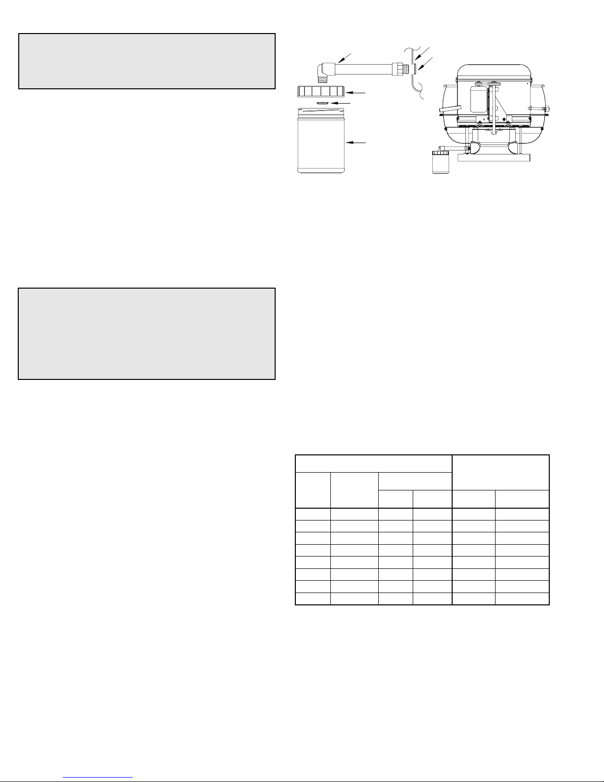
Grease Terminator Installation
WARNING
All wires must be protected from abrasion when
passing through the opening of a field wiring compartment.
Wiring Installation
All wiring should be in accordance with local ordinances
and the National Electrical Code, NFPA 70. Ensure the
power supply (voltage, frequency, and current carrying
capacity of wires) is in accordance with the motor nameplate. Refer to the Wiring Diagrams, next page.
Do not use cooling tubes for electrical connections.
Upblast units have two wiring conduits . Upblast units have
two wiring conduits. The vertical conduit comes plugged.
The horizontal conduit is dire ctly above vertica l conduit.
! CAUTION ! Do not use vertical conduit if fan will be used
in a grease and/or heat exhaust application, use of the vertical conduit does not conform to NFPA 96 and UL 762.
Lock off all power sources before the fan is wired to
power source.
Personal Safety
Disconnect switches are recommended. Place
the disconnect switch near the fan in order that
the power can be swiftly cut off in case of an
emergency, and in order that maintenance personnel are provided complete control of the
power source.
Follow the wiring diagram in the disconnect switch
and the wiring diagram provided with the motor. Correctly label the circuit on the main power box and
always identify a closed switch to promote safety (i.e.,
red tape over a closed switch).
Fan With a Junction Box
a. Wire the motor using the junction box located on the
outside of the fan.
b. Reinstall the junction box cover and ensure that the
gasket forms a complete seal.
Fan Without a Junction Box
A field wiring compartment must be installed for wire connections. Wire the motor by pulling the electrical wire
through the conduit. For further information refer to the
National Electrical Code and the wiring diagram provided on
the motor.
PVC
Extension
Lid
Sealing Nut
Terminator
Fan Inlet Side
Sealing Nut
VCR with Terminator
Final Installation Steps
a. Ensure fasteners and setscrews, particularly fan
mounting and bearing fasteners, are tightened according to the recommended torque shown in the table
below, Recommended Torque for Setscrews/Bolts.
b. Inspect for correct voltage with voltmeter.
c. Ensure all accessories are installed.
d. Test the fan to be sure the rotation is the same as indi-
cated by the arrow marked Rotation.
Do not allow the fan to run in the wrong direction.
This will overheat the motor and cause serious damage. For 3-phase motors, if the fan is running in the
wrong direction, check the control switch. It is possible to interchange two leads at this location so that the
fan is operating in the correct direction.
e. Inspect wheel-to-inlet clearance. Wheels may shift in
shipment. To realign wheel-to-inlet, shift u pper be aring
so there is an equal radial clearance between the
wheel and inlet.
Recommended Torque for Setscrews/Bolts (IN/LB.)
Setscrews
Size
No.10 3/32” 28 33 3/8”-16 240
1/4” 1/8” 66 80 1/2”-13 600
5/16” 5/32” 126 156 5/8”-11 1200
3/8” 3/16” 228 275 3/4”-10 2100
7/16” 7/32” 29 348 7/8”-9 2040
1/2” 1/4” 42 504 1”-8 3000
5/8” 5/16” 92 1104 1-1/8”-7 4200
3/4” 3/8” 120 1440 1-1/4”-7 6000
Key Hex
Across
Flats
Recommended
Torque
Min. Max. Size
Hold Down Bolts
Wrench
Torque
2
Page 3
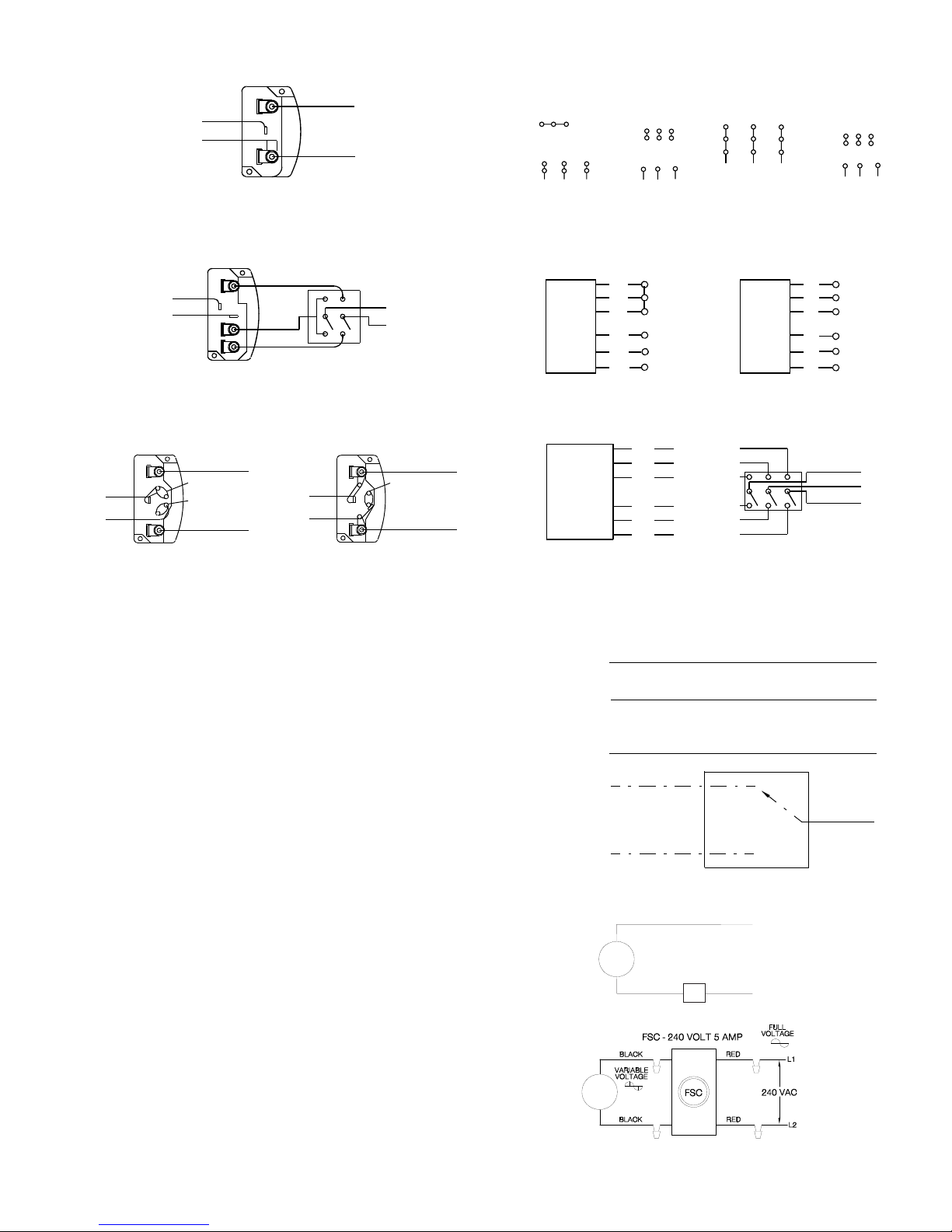
Wiring Diagrams
Single Speed, Single Phase Motor
Ground A
L
T-1
T-4
Ground B
When ground is required, attach to ground A or B with no. 6 thread forming
screw. To reverse, interchange T-1 and T-4.
1
Line
L
2
Wiring Diagrams
3 Phase, 9 Lead Motor
Y-Connection
Low Voltage
208/230 Volts
4
5
6
3
1
9
728
L2L
L
1
To reverse, interchange any 2 line leads.
3
High Voltage
460 Volts
456
789
3
12
L2L
L
1
3 Phase, 9 Lead Motor
Delta-Connection
Low Voltage
208/230 Volts
L
3
8
7
4
6
2
1
L
1
2
2 Speed, 2 Winding, Single Phase Motor 2 Speed, 1 Winding, 3 Phase Motor
Ground A
T-1
T-4
Ground B
When ground required, attach to ground A or B with No. 6 thread forming
screw. To reverse, interchange T-1 and T-4 leads.
High Speed
L
1
L
2
Low Speed
Line
1
Together
2
Motor
3
L
1
4
L
5
2
6
Line
L
3
Motor
To reverse, interchange any 2 line leads. Motors require magnetic control.
Single Speed, Single Phase, Dual Voltage 2 Speed, 2 Winding, 3 Phase
Ground A
L
T-5
J-10
Ground B
Link A
Link B
Low Voltage
Line
L
1
T-5
J-10
2
Ground B
When ground required, attach to ground A or B with No. 6 thread forming
screw. To reverse, interchange T-5 and J-10 leads.
Ground A
Link A & B
High Voltage
L
1
Line
L
2
T
Low Speed
3
Low Speed
T
2
Low Speed
T
Motor
T
T
T
1
11
12
13
High Speed
High Speed
High Speed
To reverse: High Speed-interchange leads T11 and T12.
Low Speed-interchange leads T
line leads.
and T2. Both Speeds-interchange any 2
1
High Voltage
1
2
3
4
5
6
460 Volts
789
456
12
L1L
L
2
L
1
L
Line
2
L
3
Open
3
3
L
1
L
2
Line
L
3
9
5
3
L
3
Low SpeedHigh Speed
Operation
Pre-Start Checks
a. Lock out all the primary and secondary power sources.
b. Inspect and tighten fasteners and setscrews, particu-
larly fan mounting and bearing fasteners. Refer to
Torque chart.
c. Inspect belt tension and pulley alignment. Refer to Belt
and Pulley Installation, page 5.
d. Inspect motor wiring. Refer to Wiring Installation, page
2.
e. Ensure belt touches only the pulleys.
f. Rotate the wheel to ensure it rotates freely.
g. Ensure fan and ductwork are clean and free of de b ris.
h. Close and secure all access doors.
i. Restore power to fan.
Start Up
Turn the fan on. In variable speed units, set the fan to its
lowest speed. Inspect for the following:
• Direction of rotation
• Excessive vibration
• Unusual noise
• Bearing noise
• Improper belt alignment or tension (listen for squealing)
• Improper motor amperage or voltage
If a problem is discovered, immediately shut the fan
off. Lock out all electrical power and check for the
cause of the trouble. Refer to Troubleshooting, page 6.
VCRD with Shade Pole or PSC Motors
White Line
Black
VCRD with 2-Speed PSC Motors
White Line
Black (High)
Red (Low)
NOTE: Insulate Unused Lead
FSC - 115 VOLT 10 AMP
VCR
FAN*
FSC
VCR
FAN*
*See VCR Wiring Diagram for correct lead.
†
Locate away from heat.
*
*
WHITE
BLACK
Line
Line
3
Page 4

Inspection
Inspection of the fan should be conducted at the first 30
minute, 8 hour and 24 hour intervals of satisfactory opera-
tion. During the inspections, stop the fan and inspect as
instructed below.
30 Minute Interval
Inspect bolts, setscrews, and motor mounting bolts.
Adjust and tighten as necessary.
8 Hour Interval
Inspect belt alignment and tension. Adjust and tighten as
necessary.
24 Hour Interval
Inspect belt tension. Adjust and tighten as necessary.
Maintenance
Establish a schedule for inspecting all parts of the fan.
The frequency of inspection depends on the operating conditions and location of the fan.
Inspect fans exhausting corrosive or contaminated air
within the first month of operation. Fans exhausting contaminated air (airborne abrasives) should be inspected
every three months.
Regular inspections are recommended for fans exhausting non-contaminated air.
It is recommended the following inspections be conducted twice per year.
• Inspect bolts and setscrews for tightness. Tighten as
necessary. Refer to Torque chart.
• Inspect belt wear and alignment. Replace worn belts
with new belts and adjust alignment as needed. Refer to
Belt and Pulley Installation, page 5.
• Bearings should be inspected as recommended in the
Conditions Chart, page 4.
• Inspect for cleanliness. Clean exterior surfaces only.
Removing dust and grease on motor housing assures
proper motor cooling.
Grease Terminator
Regular inspections of the Grease Terminator 2 are recommended. Depending on the amount of greas e discharged through the fan, the Grease Terminator 2 should
be changed every 30 to 45 days to ensure proper operation. Any buildup of grease is easily seen during a visual
inspection of the clear canister. However, if the Grease Ter minator 2 becomes saturated, grease will no longer be
absorbed.
To replace the Grease Terminator, simply unscrew the
used canister and screw on a new one.
Lubricants
Loren Cook Company uses petroleum lubricant in a lithium base conforming to NLGI grade 2 consistency. Other
grades of grease should not be used unless the bearings
and lines have been flushed clean. If another grade of
grease is used, it should be lithium-based.
A NLGI grade 2 grease is a light viscosity, low-torque,
rust-inhibiting lubricant that is water resistant. Its temperature range is from -30°F to +200°F and capable of intermittent highs of +250°F.
Motor Bearings
Motor bearings are pre-lubricated and sealed. Under no r-
mal conditions they will not require further maintenance for
a period of ten years. However, it is advisable to have your
maintenance department remove and disassemble the
motor, and lubricate the bearings after three years of operation in excessive heat or in a contaminated airstream consisting of airborne abrasives.
Fan Bearings
Fan bearings are lubricated through the grease fitting and
should be lubricated by the schedule, Conditions Chart,
shown below.
For best results, lubricate the bearing while the fan is rotating. Slowly pump grease into the bearing until a slight bead
forms around the bearing seals. Excessive grease can burst
seals thus reduce bearing life.
In the event the bearing cannot be seen, use no more than
three injections with a hand-operated grease gun.
Conditions Chart
RPM Temperature
100 Up to 120°F Clean 6 to 12 months
500 Up to 150°F Clean 2 to 6 months
1000 Up to 210°F Clean 2 weeks to 2 months
1500 Over 210°F Clean Weekly
Any
Speed
Any
Speed
Any
Speed
Any
Speed
Up to 150°F Dirty 1 week to 1 month
Over 150°F Dirty Daily to 2 weeks
Any Temperature Very Dirty Daily to 2 weeks
Any Temperature
Fan
Status
Extreme
Conditions
Greasing
Interval
Daily to 2 weeks
Motor Services
Should the motor prove defective within a one-year period,
contact your local Loren Cook representative or your nearest
authorized electric motor service representative.
Changing Shaft Speed
All belt driven ventilators (5HP or less) are equipped with
variable pitch pulleys. To change the fan speed, per for m the
following:
a. Loosen setscrew on driver (motor) pulley and remove
key, if equipped.
b. Turn the pulley rim to open or close the groove facing. If
the pulley has multiple grooves, all must be adjusted to
the same width.
c. After adjustment, inspect for proper belt tension.
Speed Reduction
Open the pulley in order that the belt rides deeper in the
groove (smaller pitch diameter).
Speed Increase
Close the pulley in order that the belt rides higher in the
groove (larger pitch diameter). Ensure that the RPM limit s of
the fan and the horsepower limits of the motor are maintained.
4
Page 5

Replacing Pulleys and Belts
1 foot
1/4 inch
a. Clean the motor and fan shafts.
b. Loosen the motor plate mounting bolts to relieve the
belt tension. Remove the belt.
c. Loosen the pulley setscrews and remove the pulleys
from the shaft.
Maximum RPM
Do not change the pulley pitch diameter to change tensi-
sion. The change will result in a different fan speed.
VCR
Size
100 2002 - 150 1952 120 1671 - 165 1728 135 1574 - 180 1829 150 1520 - 195 1570 165 1295 - 210 1626 180 1546 - 225 1435 195 1353 - 245 1185 1234
210 1227 - 270 1025 1049
225 1086 - 300 980 1046
245 901 - 330 830 912
270 766 - 365 735 872
300 837 877
330 716 748
365 624 659
402 539 560
445 463 473
490 360 403
Maximum RPM
Standard Reinforced Standard Reinforced
VCR-HP
Size
Maximum RPM
Maximum RPM
VCR-XP
Size
165 2508 245 1616
180 2396 270 1656
195 2100 300 1391
210 2126 330 1182
225 1879 365 1132
Maximum RPM
Standard Standard
VCR-XP
Size
If excessive force is required to remove the pul-
leys, a three-jaw puller can be used. This tool,
however, can easily warp a pulley. If the puller is
used, inspect the trueness of the pulley after it is
removed from the shaft. The pulley will need
replacement if it is more than 0.020 inch out of
true.
d. Clean the bores of the pulleys and place a light coat of
oil on the bores.
e. Remove grease, rust and burrs from the pulleys.
f. Place fan pulley on the fan shaft and the motor pulley
on the motor shaft. Damage to the pulleys can occur
when excessive force is used in placing the pulleys on
their respective shafts.
g. After the pulleys have been correctly placed back onto
their shafts, tighten the pulley setscrews.
Belt and Pulley Installation
Belt tension is determined by the sound of the belts when
the fan is first started. The belts will produce a loud squeal,
which dissipates after the fan is operating at fu ll cap acity. If
belt tension is too tight or too loose, lost efficiency and
damage can occur.
Maximum RPM
Figure 1
a. Loosen motor plate adjustment bolts and move motor
plate so that the belts easily slip into the grooves on
the pulleys. Never pry, roll, or force the belts over the
rim of the pulley.
b. Slide the motor plate back until proper tension is
reached. For proper tension, a deflection of approximately 1/4” per foot of center distance should be
obtained by firmly pressing the belt. Refer to Figure 1.
c. Lock the motor plate adjustment bolts in place.
d. Ensure pulleys are properly aligned. Refer to Figure 2.
Tolerance
Center Distance
Up thru 12” 1/16”
12” up through 48 1/8”
Over 48” 1/4”
Figure 2
Maximum
Gap
OFFSET ANGULAR OFFSET/ANGULAR
A
W
B
CENTER
DISTANCE
(CD)
GAP
X
Y
Z
GAP
Pulley Alignment
Pulley alignment is adjusted by loosening the motor pulley setscrew and by moving the motor pulley on the motor
shaft.
Figure 2 indicates where to measure the
allowable gap for the drive alignment tolerance. All contact points (indicated by
WXYZ) are to have a gap less than the tolerance shown in the table. When the pulleys are not the same width, the allowable
gap must be adjusted by half of the difference in width. Figure 3 illustrates using a
carpenter’s square to adjust the position of
the motor pulley until the belt is parallel to
Figure 3
the longer leg of the square.
Bearing Replacement
The fan bearings are pillow block type ball bearings.
a. Remove the old bearing.
b. Remove any burrs from the shaft by sanding.
c. Slide new bearings onto the shaft to the desired loca-
tion and loosely mount bearings onto the bearing support. Bearing bolts and setscrews should be loose
enough to allow shaft positioning.
5
Page 6

d. Correctly position the wheel and tighten the bearing
bolts securely to the bearing support.
e. Align setscrews bearing to bearing and secure tightly
to the shaft.
Never tighten both pair s of setscrews before secur-
ing bearing mounting bolts. This may damage the
shaft.
f. Inspect the wheel position again. If necessary, readjust
by loosening the bearing bolts and setscrews and
repeat from step e.
g. Test run the fan.
h. Retighten setscrews on bearings, sheave and wheel.
Recheck belt tension and adjust as needed.
Wheel Replacement
a. Drill two holes approximately centered between the
shaft and the edge of the hub OD with the following
dimensions:
• 1/4” diameter
• 3/8” to 1/2” deep
• 180° apart in face of hub
b. Tap 1/4” holes to 5/16” thread with the 5/16” hole tap.
Do not drill or tap any larger than recommended.
c. Screw the puller arms into the tapped holes full depth
of threads (3/8” to 1/2” approximately). Align center of
puller with center of shaft. Make certain all setscrews
in hub (normally a quantity of two) are fully removed.
Work puller slowly to back wheel off the shaft
Recommended Puller
Lisle No. 45000 Sterling Wheel Puller. This puller is available at most automotive parts retail outlets.
cone and the edge of the inlet) is obtained by loosening th e
inlet cone bolts and repositioning the inlet cone.
Radial Clearance
Wheel/Inlet Overlap
Maximum
Size
100
120 330
135 365
150 402
165 445
180 490
195 540
210
225 660
245 730
270
Overlap
Overlap
5/8”
3/4”
Size
300
600
Maximum
Overlap
1”
1-1/4”
Troubleshooting
Problem and Potential Cause
Low Capacity or Pressure
•Incorrect direction of rotation. Make sure the fan rotates in same direction as the arrows on the motor or belt drive assembly.
•Poor fan inlet conditions. There should be a straight clear duct at the
inlet.
•Improper wheel alignment.
Excessive Vibration and Noise
•Damaged or unbalanced wheel.
•Belts too loose; worn or oily belts.
•Speed too high.
•Incorrect direction of rotation. Make sure the fan rotates in same direction as the arrows on the motor or belt drive assembly.
•Bearings need lubrication or replacement.
•Fan surge.
Wheel Replacement Components
Above - Drilled hole placement.
Right - Wheel puller.
Wheel-to-Inlet Clearance
The correct wheel-to-inlet clearance is critical to proper
fan performance. This clearance should be verified before
initial start-up since rough handling during shipment could
cause a shift in fan components. Refer to wheel/inlet drawing for correct overlap.
Adjust the overlap by loosening the wheel hub and moving the wheel along the shaft to obtain the correct value.
A uniform radial gap (space between the edge of the
Overheated Motor
•Motor improperly wired.
•Incorrect direction of rotation. Make sure the fan rotates in same direction as the arrows on the motor or belt drive assembly.
•Cooling air diverted or blocked.
•Improper inlet clearance.
•Incorrect fan RPMs.
•Incorrect voltage.
Overheated Bearings
•Improper bearing lubrication
•Excessive belt tension.
6
Page 7

Parts List
VCR/VCR-HP/VCR-XP Parts
1a
1b
3
12
21
20
4
13
23
10
11
17
19
22
18
16
14
Part
No.
1a Top Cap Lid Top Cap Lid Top Cap Lid
1b Top Cap Cylinder Top Cap Cylinder Top Cap Cylinder
2 Top Cap Clip (4) Top Cap Clip (4) Top Cap Clip (8)
3 Motor Motor Motor
2
15
9
24
9
5
6
8
7
4 Spun Motor Plate Spun Motor Plate Spun Motor Plate
5 Baffle Baffle Baffle
6 Wheel Assembly Wheel Assembly Wheel Assembly
7BaseBaseBase
8 Conduit Conduit Conduit
9 Isolator (4) Isolator (4) Isolator (4)
10 Upper Post (4) Upper Post (4) Upper Post (8)
11 Lower Post (4) Lower Post (4) Lower Post (8)
12 Wind Band Wind Band Wind Band
13 Brace (4) Brace (4) Brace (8)
14 Power Assembly Power Assembly Power Assembly
15 Shaft Shaft Shaft
16 Bearing (2) Bearing (2) Bearing (2)
17 Drive Sheave Drive Sheave Drive Sheave
18 Driven Sheave Driven Sheave Driven Sheave
19 Belt Set Belt Set Belt Set
20 Vent Tube Vent Tube Vent Tube
21 Grommet (2) Grommet (2) Grommet (2)
22 — Cut Off (HP & XP Only ) Cut Off (HP & XP Only )
23 Insulation Insulation Insulation
24 NEMA 3 Junction Box NEMA 3 Junction Box NEMA 3 Junction Box
VCR/VCR-HP/VCR-XP Parts Description
100-225 245 270-490
VCRD/VCRD-HP/VCRD-XP Parts
1a
3
1b
13
15
16
4
14
Part
No.
2
1a Top Cap Lid
VCRD/VCRD-HP/VCRD-XP Parts Description
100-195
1b Top Cap Cylinder
2 Top Cap Clip (4)
3 Motor
7
4 Spun Motor Plate
5Baffle
6 Wheel Assembly
5
6
11
9
12
7 NEMA 3 Junction Box
8Base
9 Conduit
11 Up per Post (4)
12 Lower Post (4)
13 Wind Band
8
14 Brace (4)
15 Vent Tube (2)
16 Grommet (4)
7
Page 8

Limited Warranty
Loren Cook Company warrants that your Loren Cook fan was manufactured free of defects in materials and workmanship, to the extent stated herein. For a period
of one (1) year after date of shipment, we will replace any parts found to be defective without charge, except for shipping costs which will be paid by you. This warranty is granted only to the original purchaser placing the fan in service. This warranty is void if the fan or any part thereof has been altered or modified from its
original design or has been abused, misuse d, d amage d or i s in worn con dit ion o r if th e fa n has b een u sed ot her tha n fo r t he uses descri bed in th e compan y manual.
This warranty does not cover defects resulting from normal wear and tear. To make a warranty claim, notify Loren Cook Company, General Offices, 2015 East
Dale Street, Springfield, Missouri 65803-4637, e xplaining in writi ng, in d etail, yo ur complaint and referr ing to the specific m odel a nd serial numbers of your fan. Up on
receipt by Loren Cook Company of your written complaint, you will be notified, within thirty (30) days of our receipt of your complaint, in writing, as to the manner in
which your claim will be handled. If you are entitled to warranty relief, a warranty adjustment will be completed within sixty (60) business days of the receipt of your
written complaint by Loren Cook Company. This warranty gives only the original purchaser placing the fan in service specifically the right. You may have other legal
rights which vary from state to state.
Corporate Offices: 2015 E. Dale Street Springfield, MO 65803 417.869.6474
lorencook.com
8
VCR IOM - October 2007
 Loading...