

COOK Lo-Pro User Manual
Lo-Pro
Low Profile Centrifugal Exhaust Fans
INSTALLATION, OPERATION, AND MAINTENANCE MANUAL
This publication contains the installation, operation and
maintenance procedures for standard units of the “Lo-Pro”
(LPD & LPB) Low Profile Centrifugal Exhaust Fans.
Carefully read this publication and any supplemental documents prior to any installation or
maintenance procedure.
Loren Cook Company LC catalog provides additional
information describing the equipment, fan performance,
available accessories, and specification data.
For additional safety information, refer to AMCA
publication 410-96, Safety Practices for Users and
Installers of Industrial and Commercial Fans.
All of the publications listed above can be obtained from
Loren Cook Company by phoning (417)869-6474,
extension 166; by FAX at (417)832-9431; or by e-mail at
info@lorencook.com.
For information and instructions on special equipment,
contact Loren Cook Company at (417)869-6474.
Receiving and Inspection
Carefully inspect the fan and accessories for any damage and shortage immediately upon receipt of the fan.
• Turn the wheel by hand to ensure it turns freely and
does not bind.
• Check dampers (if included) for free operation of all
moving parts.
• Record on the Delivery Receipt any visible sign of
damage.
Handling
Lift the fan by the base or by the shipping carton.
NOTICE! Never lift by the shaft, motor or housing.
Rotating Parts & Electrical Shock Hazard:
Disconnect electric power before working on unit.
Follow proper lockout / tagout procedures to ensure
the unit cannot be energized while being installed or
serviced.
A disconnect switch should be placed near the fan in
order that the power can be swiftly cut off, in case of
an emergency and in order that maintenance
personnel are provided complete control of the power
source.
Grounding is required. All field-installed wiring must
be completed by qualified personnel. All fieldinstalled wiring must comply with National Electric
Code (NFPA 70) and all applicable local codes.
Failure to follow these instructions could result in
death or serious injury.
Storage
If the fan is stored for any length of time prior to installation, store it in its original shipping crate and protect it from
dust, debris and the weather.
Installation
The attachment of roof mounted fans to the roof curb
as well as the attachment of roof curbs to the building
structure must exceed the structural requirements
based on the environmental loading derived from the
applicable building code for the site. The local code
official may require variations from the recognized
code based on local data. The licensed engineer of
record will be responsible for prescribing the correct
attachment based on construction materials, code
requirements and environmental effects specific to
the installation.
Failure to follow these instructions could result in
death or serious injury.
To prevent damage to the fan during shipping, motors 5
HP and larger, and extremely heavy motors (cast iron or
severe duty) are shipped loose and must be field mounted
by bolting the motor on the motor mounting plate in the
existing mounting slots.
Damper Installation
If your fan is supplied with dampers, follow the directions
below. If your fan does not include dampers, proceed to
Belt and Pulley Installation.
a. Place the damper inside the curb. Ensure the damper
will open freely for the correct direction of the airflow.
b. Secure to curb at the damper shelf.
c. Drill a hole in the curb shelf for conduit needed for
motor wiring.
d. Operate the dampers manually to ensure the baldes
move freely.
e. Install ventilator over curb.
Lo-Pro
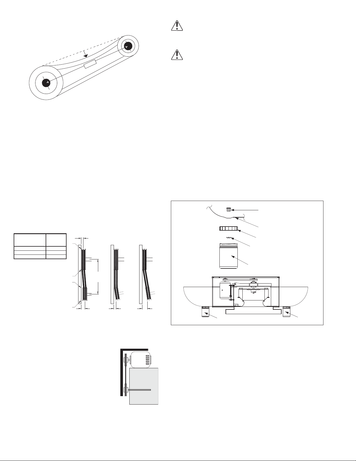
Conduit Nipple
Diverter
Terminator Lid
Sealing Nut
Terminator
Terminator
Terminator
Roof Top Installation Shown
Figure 4
Wall Installation
1 foot
1/4 inch
a. Position unit so that hinge on topcap is facing down.
Belt and Pulley Installation
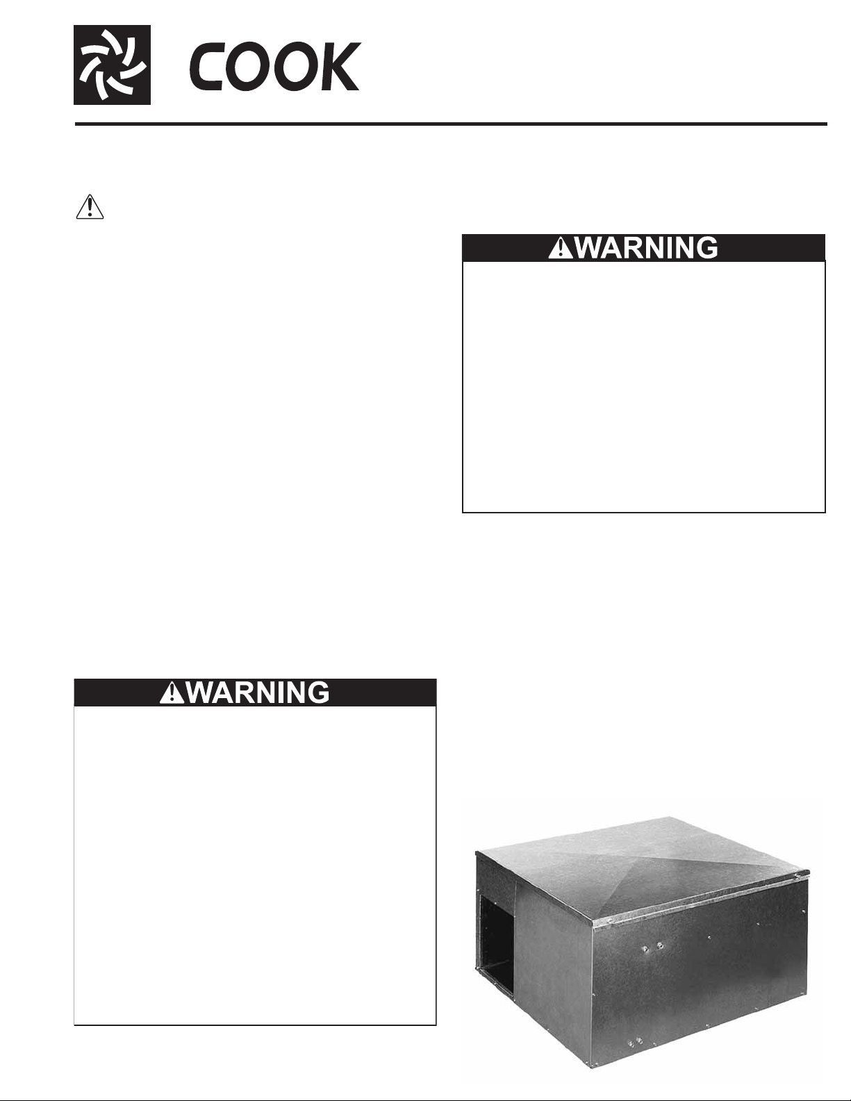
Figure 1
Belt tension is determined by the sound of the belts when
the fan is first started. The belts will produce a loud squeal,
which dissipates after the fan is operating at full capacity . If
belt tension is too tight or too loose, lost efficiency and
damage can occur.
Do not change the pulley pitch diameter to change tension. The change will result in a different fan speed. )
a. Loosen the motor plate adjustment nuts on motor
base and move motor plate in order that the belts can
easily slip into the grooves on the pulleys. Never pry,
roll, or force the belts over the rim of the pulley.
b. Adjust the motor plate until proper tension is reached.
For proper tension, a deflection of approximately 1/4”
per foot of center distance should be obtained by
firmly pressing the belt. Refer to Figure 1.
c. Lock the motor plate adjustment nuts in place.
d. Ensure pulleys are properly aligned. Refer to Figure 2.
Tolerance
Center Distance
Up thru 12” 1/16”
12” up through 48 1/8”
Over 48” 1/4”
Figure 2
Maximum
Gap
OFFSET ANGULAR OFFSET/ANGULAR
A
W
X
Y
CENTER
DISTANCE
(CD)
Wiring Installation
All wiring should be in accordance with local
ordinances and the National Electrical Code,
NFPA 70. Ensure the power supply (voltage, frequency, and current carrying capacity of wires)
is in accordance with the motor nameplate.
Refer to the Wiring Diagrams, next page.
Leave enough slack in the wiring to allow for motor movement when adjusting belt tension. Some fractional motors
have to be removed in order to make the connection with
the terminal box at the end of the motor.
NOTICE! Follow the wiring diagram in the disconnect
switch and the wiring diagram provided with the motor.
Correctly label the circuit on the main power box and
always identify a closed switch to promote safety (i.e.,
red tape over a closed switch).
Optional Diverter
a. Position diverter so that air flow is directed up.
b. Seal between diverter flange and unit side panel with
RTV 400 silicone. (RTV Silicone is NOT supplied.)
c. Use screws provided to secure diverter to unit.
Optional Grease Terminator Installation
a. Attach hardware to drain hole in the diverter.
See Figure 4.
b. Screw new canister into lid.
Roof Top Installation Shown
Conduit Nipple
Diverter
Terminator Lid
Sealing Nut
Terminator
Z
B
Pulley Alignment
Pulley alignment is adjusted by loosening the motor pulley
setscrew and by moving the motor pulley on the motor shaft.
Figure 2 indicates where to measure
GAP
GAP
the allowable gap for the drive alignment
tolerance. All contact points (indicated by
WXYZ) are to have a cap less than the
tolerance shown in the table. When the
pulleys are not the same width, the allowable gap must be adjusted by half of the
difference in width. Figure 3 illustrates
using a carpenter’s square to adjust the
position of the motor pulley until the belt
Figure 3
is parallel to the longer leg of the square.
Terminator
Figure 4
Terminator
Final Installation Steps
a. Inspect fasteners and setscrews, particularly fan
mounting and bearing fasteners, and tighten according
to the recommended torque shown in the table on
page 4, Recommended Torque for Setscrews/Bolts.
b. Inspect for correct amperage and voltage with an
ammeter and voltmeter.
c. Ensure all accessories are installed.
d. Check wheel-to-inlet clearance on power roof fans.
e. Test the fan to be sure the rotation is the same as indi-
cated by the arrow marked ‘Rotation’.
NOTICE! Do not allow the fan to run in the wrong
direction. This will overheat the motor and cause serious damage. For 3-phase motors, if the fan is running
2
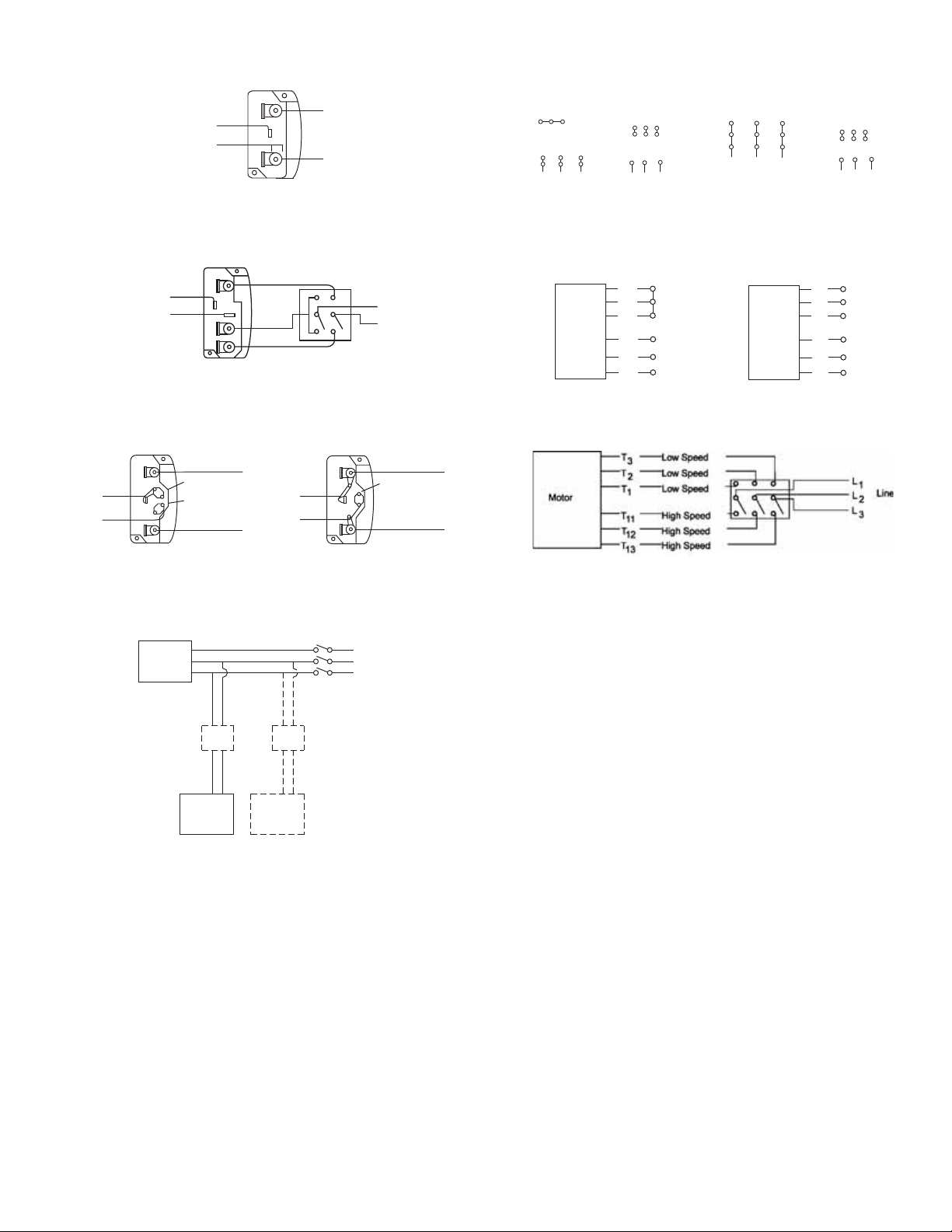
Wiring Diagrams
Single Speed, Single Phase Motor
Ground A
L
T-1
T-4
Ground B
When ground is required, attach to ground A or B with no. 6 thread forming
1
Line
L
2
Wiring Diagrams
3 Phase, 9 Lead Motor
Y-Connection
Low Voltage
208/230 Volts
4
5
6
3
1
9
728
L2L
L
1
To reverse, interchange any 2 line leads.
3
High Voltage
460 Volts
456
789
3
12
L2L
L
1
208/230 Volts
3
3 Phase, 9 Lead Motor
Delta-Connection
Low Voltage
8
7
4
6
2
1
L
1
screw. To reverse, interchange T-1 and T-4.
2 Speed, 2 Winding, Single Phase Motor 2 Speed, 1 Winding, 3 Phase Motor
Ground A
High Speed
T-1
T-4
L
1
Line
L
2
Low Speed
Ground B
When ground required, attach to ground A or B with No. 6 thread forming
screw. To reverse, interchange T-1 and T-4 leads.
Motor
To reverse, interchange any 2 line leads. Motors require magnetic control.
High Speed
1
Together
2
3
L
4
1
L
5
6
L
Motor
2
Line
3
Single Speed, Single Phase, Dual Voltage 2 Speed, 2 Winding, 3 Phase
Ground A
L
T-5
J-10
Link A
Link B
Low Voltage
Ground B
Line
L
1
T-5
J-10
2
Ground B
When ground required, attach to ground A or B with No. 6 thread forming
screw. To reverse, interchange T-5 and J-10 leads.
Ground A
Link A & B
L
Line
L
1
2
To reverse: High Speed-interchange leads T11 and T12.
Low Speed-interchange leads T1 and T2. Both Speeds-interchange any 2
line leads.
Typical Damper Motor Schematic
9
5
3
L
3L2
Low Speed
1
2
3
4
5
6
High Voltage
460 Volts
789
456
3
12
L1L
L
3
2
L
1
L
2
Line
L
3
Open
Fan
Motor
Transformer**
Damper
Motor*
Second
Damper
Motor
L3
L2
L1
Transformer**
For 3 phase, damper motor voltage should be the same between L1 and
L2. For single phase application, disregard L3. *Damper motors may be
available in 115, 230 and 460 volt models. The damper motor nameplate
voltage should be verified prior to connection. **A transfomer may be provided in some installations to correct the damper motor voltage to the
specified voltage.
3
 Loading...