


ASP/KSP
Centrifugal Filtered Supply Fans
INSTALLATION, OPERATION, AND MAINTENANCE MANUAL
This publication contains the installation, operation and maintenance instructions for standard
units of the ASP/KSP-Centrifugal Filtered Supply
Fans.
Carefully read this publication prior to any installation or maintenance procedure.
Loren Cook catalog, ASP/ASP-T and KSP, provides
additional information describing the equipment, fan
performance, available accessories, and specification
data.
For additional safety information, refer to AMCA publication 410-96, Safety Practices for Users and Install-
ers of Industrial and Commercial Fans.
All of the publications listed above can be obtained
from Loren Cook Company by phoning 417/869-6474,
extension 166; by FAX at 417/832-9431; or by e-mail at
info@lorencook.com.
For information on special equipment, contact Loren
Cook Company Customer Service Department at 417/
869-6474.
Receiving and Inspection
Carefully inspect the fan and accessories for any
damage and shortage immediately upon receipt of the
fan.
• Turn the wheel by hand to ensure it turns freely and
does not bind.
• Inspect dampers (if supplied) for free operation of
all moving parts.
• Record on the Delivery Receipt any visible sign of
damage.
Installation
Motor Installation
To prevent damage to the fan during shipping, motors 5 HP
and larger, and extremely heavy motors (cast iron or severe
duty) are shipped loose and must be field mounted by bolting
the motor on the motor mounting plate in the existing mounting
slots.
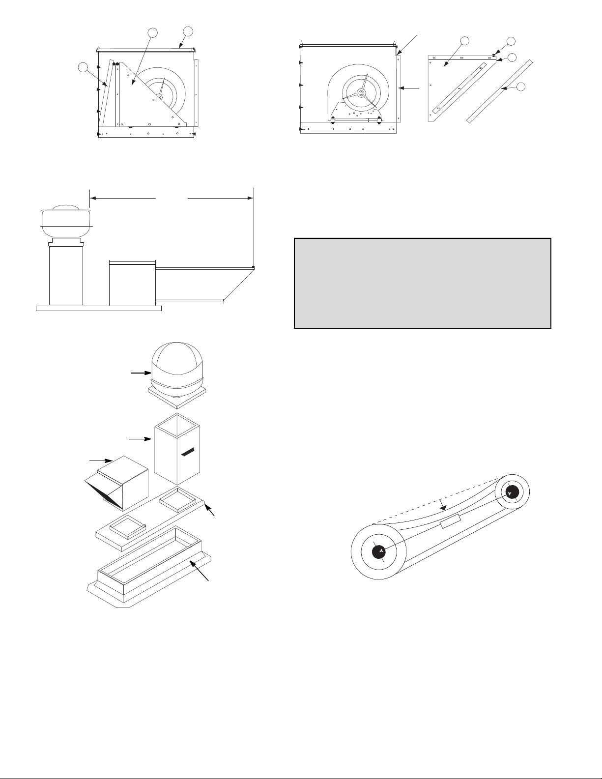
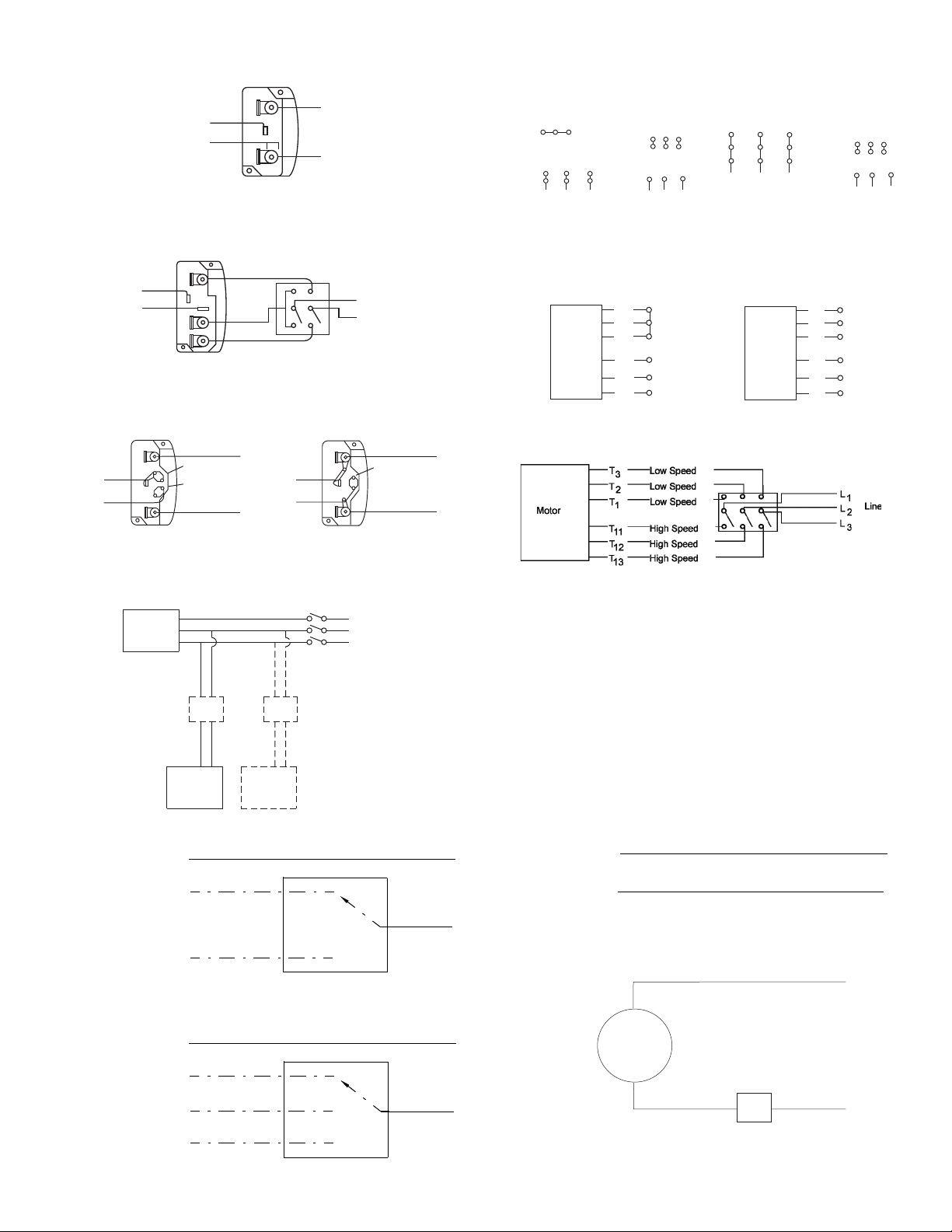
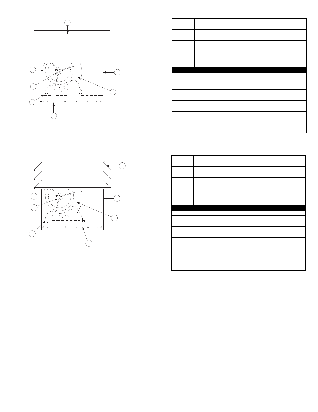
KSP Assembly
NFPA 96 installation guidelines for KSP fans are shown in
figure 1 and 2 on page 2.
a. Remove the top cap (item 3) from the fan.
b. Remove the intake hood (item 2) and the filter(s) (item 1)
from the inside of the fan.
c. Replace the topcap.
d. Slide the intake hood over the flange on the fan and
secure with the nine screws provided.
e. Remove the two thumb screws and the filter retainer.
f. Slide the filter(s) down between the angles inside the
intake hood and the flange on the front of the hood.
g. Replace the filter retainer and secure with the two thumb
screws.
h. Caulk the top of the intake hood where the hood meets
the fan. Use an appropriate caulk for exterior use.
Handling
Lift the fan by the base or lifting eyes. Never lift by the
shaft, motor, or housing.
Storage
If the fan is stored for any length of time prior to
installation, store the fan in its original crate and protect
it from dust, debris and the weather.
WARNING
This unit has rotating parts. Safety precautions
should be exercised at all times during installation,
operation, and maintenance.
ALWAYS disconnect power prior to working on fan.
ASP
KSP
1 foot
1/4 inch
10' MIN.
2
nt
1
2 4
CaulkCaulk
5
View 2 - KSP Field Assembly
1
3
View 1 - KSP Shipping Arrangeme
10' MIN.
Figure 1 - NFPA 96 Standard Installation
VCR with Hinged Base
Vented Extension
KSP with
Intake
Extension
View 2 - KSP Field Assembly
Leave enough slack in the wiring to allow for motor
movement when adjusting belt tension. Some fractional
motors have to be removed in order to make the connection with the terminal box at the end of the motor. To
remove motor, remove bolts securing motor base to power
assembly. Do not remove motor mounting bolts.
Personal Safety
Disconnect switches are recommended. Place the
disconnect switch near the fan in order that the
power can be swiftly cut off in case of an
emergency, and in order that maintenance
personnel are provided complete control of the
power source.
Follow the wiring diagram in the disconnect switch
and the wiring diagram provided with the motor. Correctly label the circuit on the main power box and
always identify a closed switch to promote safety (i.e.,
red tape over a closed switch).
Do not allow the fan to run in the wrong direction.
This will overheat the motor and cause serious damage. For 3-phase motors, if the fan is running in the
wrong direction, check the control switch. It is possible to interchange two leads at this location so that the
fan is operating in the correct direction.
Curb Cap
Curb
Figure 2 - NFPA 96 Alternate Installation
Wiring Installation
All wiring should be in accordance with local ordinances
and the National Electrical Code, NFPA 70. Ensure the
power supply (voltage, frequency, and current carrying
capacity of wires) is in accordance with the motor nameplate.
Lock off all power sources before unit is wired to
power source.
Figure 3
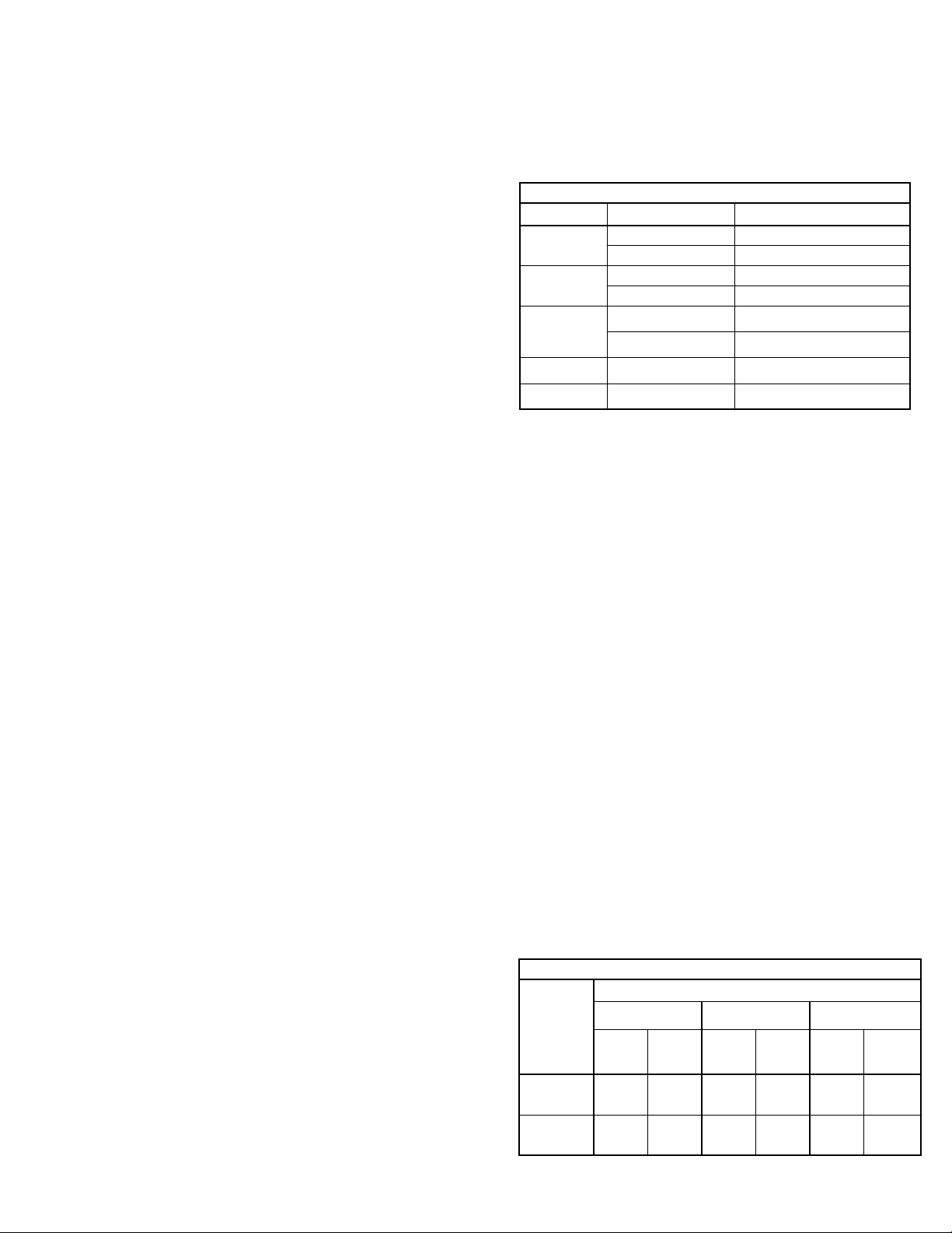
Belt and Pulley Installation
Belt tension is determined by the sound the belts make
when the fan is first started. Belts will produce a loud
squeal which dissipates after the fan is operating at full
capacity. If the belt tension is too tight or too loose, lost efficiency and possible damage can occur.
2
Wiring Diagrams
Single Speed, Single Phase Motor
Ground A
L
T-1
T-4
Ground B
When ground is required, attach to ground A or B with no. 6 thread forming
screw. To reverse, interchange T-1 and T-4.
2 Speed, 2 Winding, Single Phase Motor
Ground A
T-1
T-4
Ground B
When ground required, attach to ground A or B with No. 6 thread forming
screw. To reverse, interchange T-1 and T-4 leads.
Single Speed, Single Phase, Dual Voltage
Ground A
L
T-5
J-10
Link A
Link B
Low Voltage
Ground B
Line
1
T-5
J-10
L
2
When ground required, attach to ground A or B with No. 6 thread forming
screw. To reverse, interchange T-5 and J-10 leads.
Typical Damper Motor Schematic
Fan
Motor
Transformer**
1
Line
L
2
High Speed
Low Speed
Ground B
Transformer**
L
1
L
2
Ground A
L3
L2
L1
Line
Link A & B
L
1
Line
L
2
For 3 phase, damper motor voltage should be the same between L1 and
L2. For single phase application, disregard L3. *Damper motors may be
available in 115, 230 and 460 volt models. The damper motor nameplate
voltage should be verified prior to connection. ** A transformer may be provided in some installations to correct the damper motor voltage to the
specified voltage.
Wiring Diagrams
3 Phase, 9 Lead Motor
Y-Connection
Low Voltage
208/230 Volts
4
5
6
3
1
9
728
L2L
L
3
1
To reverse, interchange any 2 line leads.
High Voltage
460 Volts
456
789
3
12
L2L
L
1
2 Speed, 1 Winding, 3 Phase Motor
High Speed
1
Together
2
Motor
3
L
4
1
L
5
2
6
L
3
To reverse, interchange any 2 line leads. Motors require magnetic control.
2 Speed, 2 Winding, 3 Phase
To reverse: High Speed-interchange leads T
Low Speed-interchange leads T1 and T2. Both Speeds-interchange any 2
line leads.
3 Phase, 9 Lead Motor
Delta-Connection
Low Voltage
208/230 Volts
8
7
4
6
2
1
L
L
1
2
3
Motor
Line
and T12.
11
9
5
3
L
3
Low Speed
1
2
3
4
5
6
High Voltage
460 Volts
789
456
3
12
L1L
L
3
2
L
1
L
2
Line
L
3
Open
Damper
Motor*
Second
Damper
Motor
KSPD 94 - 97 and 103-106 Series
White Line
Black (High)
Red (Low)
NOTE: Insulate Unused Lead
KSPD 122 - 127 Series
White Line
Black (High)
Blue (Medium)
Red (Low)
NOTE: Insulate Unused Leads Separately
KSPD 98 and 99 Series
White Line
*
Black
Line
Line
*
FSC
WHITE
KSPD
FAN*
*
*
*
Line
*See KSPD Wiring Diagram for correct lead.
3
FSC
BLACK

Belt and Pulley Installation (cont.)
Do not change the pulley pitch diameter to change ten-
sion. This will result in a different fan speed than desired.
a. Loosen motor plate adjustment screw and move motor
plate in order that the belts can easily slip into the
grooves on the pulleys. Never pry, roll, or force the
belts over the rim of the pulley.
b. Slide the motor plate back until proper tension is
reached. For proper tension a deflection of approximately 1/4” per foot of center distance should be
obtained by firmly pressing the belt. Refer to Figure 3.
c. Lock the motor plate adjustment nuts in place.
d. Ensure pulleys are properly aligned. Refer to Figure 4.
Pulley Alignment
Pulley alignment is adjusted by loosening the motor pulley
setscrew and by moving the motor pulley on the motor shaft.
Figure 4 indicates where to measure the allowable gap
for the drive alignment tolerance. All contact points (indicated by WXYZ) are to have a gap less than the tolerance
shown in the table. When the pulleys are not the same
width, the allowable gap must be adjusted by half of the difference in width. Figure 5 illustrates using a carpenter’s
square to adjust the position of the motor pulley until the
belt is parallel to the longer leg of the square.
Tolerance
Center Distance
Up thru 12” 1/16”
12” up through 48 1/8”
Over 48” 1/4”
Maximum
Gap
OFFSET ANGULAR OFFSET/ANGULAR
A
W
f. Ensure fan and ductwork are clean and free of debris.
g. Close and secure all access doors.
h. Restore power to the fan.
Start Up
Turn the fan on. In variable speed units, set the fan to its
lowest speed and inspect for the following:
• Direction of rotation.
• Excessive vibration.
• Unusual noise.
• Bearing noise.
• Improper belt alignment or tension (listen for squealing).
• Improper motor amperage or voltage.
If a problem is discovered, immediately shut the fan
off. Lock out all electrical power and check for the
cause of the trouble. See Troubleshooting.
Recommended Torque for Setscrews/Bolts (IN/Lb
Setscrews
Size
No.10 3/32” 28 33 3/8”-16 240
1/4” 1/8” 66 80 1/2”-13 600
5/16” 5/32” 126 156 5/8”-11 1200
3/8” 3/16” 228 275 3/4”-10 2100
7/16” 7/32” 348 384 7/8”- 9 2040
1/2” 1/4” 504 600 1”- 8 3000
5/8” 5/16” 1104 1200 1-1/8” - 7 4200
3/4” 3/8” 1440 1800 1-1/4” - 7 6000
Key Hex
Across
Flats
Recommended
Torque
Min. Max. Size
Hold Down Bolts
)
Wrench
Torque
Figure 4
X
Y
Z
B
CENTER
DISTANCE
(CD)
GAP
Final Installation Steps
a. Inspect fasteners and setscrews, particularly fan
mounting and bearing fasteners, and tighten according
to the recommended torque shown in the table Recom-
mended Torque for Setscrews/Bolts.
b. Inspect for correct voltage with volt-
meter.
c. Ensure all accessories are installed.
d. If applicable, ensure fan is secureld
to ductwork.
Operation
Pre-Start Checks
a. Lock out all the primary and second-
ary power sources.
b. Ensure fasteners and setscrews, par-
ticularly those used for mounting the
fan, are tightened.
c. Inspect belt tension and pulley alignment.
d. Inspect motor wiring.
e. Ensure belt touches only the pulleys.
Figure 5
GAP
Inspection
Inspection of the fan should be conducted at the first 30
minute, 8 hour and 24 hour intervals of satisfactory opera-
tion. During the inspections, stop the fan and inspect as per
the Conditions Chart.
30 Minute Interval
Inspect bolts, setscrews, and motor mounting bolts.
Adjust and tighten as necessary.
8 Hour Interval
Inspect belt alignment and tension. Adjust and tighten as
necessary.
24 Hour Interval
Inspect belt tension. Adjust and tighten as necessary.
4
Filters
Filter inspection and cleaning intervals can vary from
once a week to twice per year depending on contaminant
present and acceptable pressure drops across the filter.
Under most conditions filters may be cleaned with hot
water and a mild soap solution (such as dish washing liquid) or steam. Some caustic cleaners will damage the filter.
If in doubt, please consult the factory for a compatibility list.
High pressure spray washers should be limited to
2,000psi operating pressure. Every attempt should be
made to remove the contaminants from the filter in a “backwash” flow (note airflow arrow on the filter frame). Once the
filter is dry, it may be returned to the appropriate filter racks
in the same orientation (airflow direction) as they were
removed.
Maintenance
Establish a schedule for inspecting all parts of the fan.
The frequency of inspection depends on the operating conditions and location of the fan.
Inspect fans exhausting corrosive or contaminated air
within the first month of operation. Fans exhausting contaminated air (airborne abrasives) should be inspected
every three months.
Regular inspections are recommended for fans exhausting non-contaminated air.
It is recommended the following inspection be conducted
twice per year.
• Inspect bolts and setscrews for tightness. Tighten as
necessary.
• Inspect belt wear and alignment. Replace worn belts
with new belts and adjust alignment as needed. Refer
to Belt and Pulley Installation, page 2.
• Bearings should be inspected as recommended in the
Conditions Chart.
• Inspect filters. Filters should be cleaned at regular intervals (frequency will depend on the environment in
which the fan is located). To remove, loosen the thumbscrews and remove the filter retainer.
• Inspect springs and rubber isolators for deterioration
and replace as needed.
• Inspect for cleanliness. Clean exterior surfaces only.
Removing dust and grease on motor housing assures
proper motor cooling. Removing dirt from the wheel
and housing prevent imbalance and damage.
Fan Bearings
The fan bearings are provided prelubricated. Any specialized lubrication instructions on fan labels supercedes
information provided herein. Bearing grease is a petroleum
lubricant in a lithium base conforming to a NLGI #2 consistency. If user desires to utilize another type of lubricant,
they take responsibility for flushing bearings and lines, and
maintaining a lubricant that is compatible with the installation.
A NLGI #2 grease is a light viscosity, low-torque, rustinhibiting lubricant that is water resistant. Its temperature
range is from -30°F to 200°F and capable of intermittent
highs of 250°F.
Bearings should be relubricated in accordance with the
condition chart below.
For best results, lubricate the bearing while the fan is in
operation. Pump grease in slowly until a slight bead forms
around the bearing seals. Excessive grease can damage
seal and reduce life through excess contamination and/or
loss of lubricant.
In the event that the bearing cannot be seen, use no more
than three injections with a hand operated grease gun.
Conditions Chart
RPM Temp °F Greasing Interval
Up to 1000
1000 to 3000
Over 3000
Any Speed < -30 Consult Factory
Any Speed > 200 1 week
For moist or otherwise contaminated installations; divide the interval by a
factor of 3. For vertical shaft installations divide the interval by a factor of 2.
-30 to 120 6 months
120 to 200 2 months
-30 to 120 3 months
120 to 200 1 month
-30 to 120 1 month
120 to 200 2 weeks
Motor Bearings
Motors are provided with prelubricated bearings. Any
lubrication instructions shown on the motor nameplate
supersede instructions below.
Direct Drive 1050/1075,1200,1300 &1500 rpm units use a
prelubricated sleeve bearing that has a oil saturated wicking
material surrounding it. The initial factory lubrication is adequate for up to 10 years of operation under normal conditions. However, it is advisable to add lubricant after 3 years.
Use only LIGHT grade mineral oil or SAE 10W oil up to 30
drops. If the unit has been stored for a year or more it is
advisable to lubricate as directed above. For VCR direct
drive units and other units in severe conditions, lubrication
intervals should be reduced to half.
Motors without sleeve bearings (as described above) will
have grease lubricated ball or roller bearings. Motor bearings without provisions for relubrication will operate up to 10
years under normal conditions with no maintenance. In
severe applications, high temperatures or excessive contaminates, it is advisable to have the maintenance department disassemble and lubricate the bearings after 3 years
of operation to prevent interruption of service.
For motors with provisions for relubrication, follow intervals of the table below.
Relubrication Intervals
NEMA Frame Size
Service
Conditions
Standard 3 yrs. 6 months 2 yrs. 6 months 1 yr. 3 months
Severe 1 yr. 3 months 1 yr. 3 months 6 months 1 months
Up to and
including 184T
1800 RPM
and less
Over 1800
RPM
213T-365T 404T and larger
1800 RPM
and less
Over 1800
RPM
1800 RPM
and less
Over 1800
RPM
5
Motors are provided with a polyurea mineral oil NGLI #2
grease. All additions to the motor bearings are to be with a
compatable grease such as Exxon Mobil Polyrex EM and
Chevron SRI.
The above intervals should be reduced to half for vertical
shaft installations.
Motor Services
Should the motor prove defective within a one-year
period, contact your local Loren Cook representative or
Maximum RPM
ASP/ASP-T
Size
90 1665 90 1672
100 1519 100 1534
120 1223 120 1297
150 1075 150 1052
180 978 180 979
200 844 200 835
your nearest authorized electric motor service representative.
Maximum
RPM
KSP
Size
Maximum
RPM
Changing Shaft Speed
All belt driven fans with motors up to and including 5 HP
are equipped with variable pitch pulleys. To change the fan
speed, perform the following:
a. Loosen setscrew on driver (motor) pulley and remove
key, if equipped.
b. Turn the pulley rim to open or close the groove facing.
If the pulley has multiple grooves, all must be adjusted
to the same width.
c. After adjustment, inspect for proper belt tension.
Speed Reduction
Open the pulley in order that the belt rides deeper in
the groove (smaller pitch diameter).
Speed Increase
Close the pulley in order that the belt rides higher in
the groove (larger pitch diameter). Ensure that the RPM
limits of the fan and the horsepower limits of the motor
are maintained.
Replacing Pulleys and Belts
a. Remove pulleys from their respective shafts.
b. Clean the motor and fan shafts.
c. Clean bores of pulleys and coat the bores with heavy
oil.
d. Remove grease, rust, or burrs from the pulleys and
shafts.
e. Remove burrs from shaft by sanding.
f. Place fan pulley on fan shaft and motor pulley on its
shaft. Damage to the pulleys can occur when exces-
sive force is used in placing the pulleys on their
respective shafts.
g. Tighten in place.
h. Install belts on pulleys and align as described in the
Belt and Pulley Installation section.
Bearing Replacement
The fan bearings for the 200 ASP, ASP-T and KSP are
pillow block ball bearings. Bearings should be replaced
individually for each side of fan.
An emery cloth or file may be needed to remove imper-
fections in the shaft left by the setscrews.
a. Remove topcap.
b. Loosen motor plate adjustment bolts, then move the
motor plate so the belt will easily slip off. Remove
driven pulley by loosening the setscrews.
c. Remove the bearings from shaft.
d. Slide new bearings onto shaft to desired location and
mount bearings loosely onto support base. Bearing
bolts and setscrews should be loose to allow shaft
positioning.
e. Position the wheel properly and tighten the bearing
bolts securely to the support base.
f. Align setscrews bearing to bearing and tighten against
the shaft securely.
Never tighten both pairs of setscrews before
securing bearing mounting bolts. This may damage the shaft.
g. Check wheel position again. If necessary, readjust by
loosening the bearing bolts and setscrew and repeat
step e.
Troubleshooting
Problem and Potential Cause
Low Capacity or Pressure
•Incorrect direction of rotation. Make sure the fan rotates in same direction as the arrows on the motor or belt drive assembly.
•Poor fan inlet conditions. There should be a straight clear duct at the
inlet.
•Improper wheel alignment.
Excessive Vibration and Noise
•Damaged or unbalanced wheel.
•Belts too loose; worn or oily belts.
•Speed too high.
•Incorrect direction of rotation. Make sure the fan rotates in same direction as the arrows on the motor or belt drive assembly.
•Bearings need lubrication or replacement.
•Fan surge.
Overheated Motor
•Motor improperly wired.
•Incorrect direction of rotation. Make sure the fan rotates in same direction as the arrows on the motor or belt drive assembly.
•Cooling air diverted or blocked.
•Improper inlet clearance.
•Incorrect fan RPMs.
•Incorrect voltage.
Overheated Bearings
•Improper bearing lubrication
•Excessive belt tension.
6
1
2
3
5
4
6
7
1
2
3
4
5
6
7
ASP Parts List
ASP-T Parts List
Side Discharge fan shown.*
Side Discharge fan shown.*
Part
No.
1 Hood
2 Housing
3 Blower
4 Base
5 Isolators (4)
6 Driven Sheave
7 Bearings (2)
Parts Not Shown
Ludwig Clip
Filter Retainer (8)
Driver Sheave
Filter (4)
Lower Retainer (4)
Corner Post (4)
Insulation
Motor Plate
Belts
Motor
Topcap
Part
No.
1 Tiered Hood
2 Housing
3 Blower
4 Base
5 Isolators (4)
6 Driven Sheave
7 Bearings (2)
Parts Not Shown
Ludwig Clip
Filter Retainer (8)
Driver Sheave
Filter (4)
Lower Retainer (4)
Corner Post (4)
Insulation
Motor Plate
Belts
Motor
Topcap
Description
Sizes 90 - 200
Description
Sizes 90 - 200
*Parts will be the same for bottom discharge units.
7

1
2
3
4
5
6
7
8
9
10
11
12
13
14
15
16
1
2
3
4
5
6
7
8
9
10
11
12
13
14
15
16
17
18
19
21
20
KSP-D Parts List
16
15
14
13
12
11
10
Part No.
1 Ludwig Clip (4) Ludwig Clip (4)
2 Topcap Topcap
3 Side Panel (2) Side Panel (2)
4 Intake Side Top Panel Intake Side Top Panel
5 Intake Top Panel Intake Top Panel
6 Intake Side Panel (2) Intake Side Panel (2)
7 Thumb Screw (2) Thumb Screw (2)
8 Nut Retainer (2) Nut Retainer (2)
9 Filter Retainer Filter Retainer
10 Filter Angle (2) Filter Angle (2)
11 Filter Filter
12 Intake Side Bottom Panel Intake Side Bottom Panel
13 Base Base
14 Motor Motor
15 Housing Housing
16 Side Panel Opposite Intake Side Panel Opposite Intake
Size 90 Sizes 91 - 121
Description
KSP-B Parts List
20
19
18
21
17
16
15
14
13
12
11
10
Part
No.
1 Ludwig Clip (4) Ludwig Clip (4)
2 Topcap Topcap
3 Blower Blower
4 Side Panel (2) Side Panel (2)
5 Intake Side Top Panel Intake Side Top Panel
6 Intake Top Panel Intake Top Panel
7 Intake Side Panel (2) Intake Side Panel (2)
8 Thumb Screw (2) Thumb Screw (2)
9 Nut Retainer (2) Nut Retainer (2)
10 Filter Retainer Filter Retainer
11 Filter Filter (2)
12 Filter Angle (2) Filter Angle (2)
13 Intake Side Bottom Panel Intake Side Bottom Panel
14 Bearings (2) Bearings (2)
15 Base Base
16 Isolator (4) Isolator (4)
17 Driven Sheave Driven Sheave
18 Side Panel Opposite Intake Side Panel Opposite Intake
19 Motor Motor
20 Motor Mount Bracket Motor Mount Bracket
21 Motor Tension Hardware Motor Tension Hardware
Size 90 - 120 Sizes 150 - 200
Description
lorencook.com
8
ASP/KSP IOM - AUG 2009
Limited Warranty
Loren Cook Company warrants that your Loren Cook fan was manufactured free of defects in materials and workmanship, to the extent stated herein. For a period of one (1)
year after date of shipment, we will replace any parts found to be defective without charge, except for shipping costs which will be paid by you. This warranty is granted only to
the original purchaser placing the fan in service. This warranty is void if the fan or any part thereof has been altered or modified from its original design or has been abused, misused, damaged or is in worn condition or if the fan has been used other than for the uses described in the company manual. This warranty does not cover defects resulting from
normal wear and tear. To make a warranty claim, notify Loren Cook Company, General Offices, 2015 East Dale Street, Springfield, Missouri 65803-4637, explaining in writing,
in detail, your complaint and referring to the specific model and serial numbers of your fan. Upon receipt by Loren Cook Company of your written complaint, you will be notified,
within thirty (30) days of our receipt of your complaint, in writing, as to the manner in which your claim will be handled. If you are entitled to warranty relief, a warranty adjustment
will be completed within sixty (60) business days of the receipt of your written complaint by Loren Cook Company. This warranty gives only the original purchaser placing the fan
in service specifically the right. You may have other legal rights which vary from state to state.
Corporate Offices: 2015 E. Dale Street Springfield, MO 65803 417.869.6474
 Loading...