

Page 1
1
Heated Makeup Direct: A Direct Fire Make-Up Air Unit
®
This installation manual provides information for
installing and conguring the Loren Cook Company HMD.
Models: HMD-2400, HMD-3400, HMD-4100.
For information and instructions on special equipment,
contact Loren Cook Company.
For additional safety information, refer to AMCA
publication 410-96, Safety Practices for Users and
Installers of Industrial and Commercial Fans. This
document and all Cook publications may be obtained from
Cook by phoning (417) 869-6474, extension 166; by FAX
at (417) 832-9431; or by e-mail at info@LorenCook.com.
All Cook publications are available on LorenCook.com.
Installation, Operation, And Maintenance Manual
Receiving and Inspection
Carefully inspect the unit and accessories for any
damage and shortage immediately upon receipt of the unit.
• Turn the blower by hand to ensure it turns freely and
does not bind.
• Record on the Delivery Receipt any visible sign of
damage.
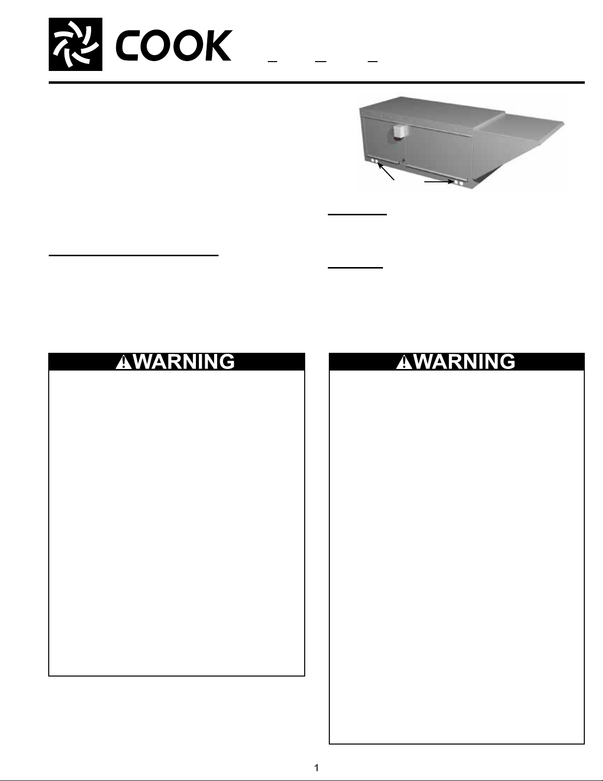
HMD
Lifting
holes
Handling
Lift unit fans by the lifting holes or by the shipping
container. Never lift by the housing.
Storage
If the fan is stored for any length of time prior to
installation, store it in its original shipping crate and protect
it from dust, debris and the weather.
Rotate the wheel several revolutions every three to ve
days to keep a coating of grease on all internal bearing
parts.
WARNING: Improper installation,
adjustment, alteration, service or
maintenance can cause property damage,
injury or death. Read the installation,
operating and maintenance instructions
thoroughly before installing or servicing this
equipment.
FOR YOUR SAFETY
If you smell gas:
1. Open windows.
2. Don’t touch electrical switches.
3. Extinguish any open ame.
4. Immediately call your gas supplier.
FOR YOUR SAFETY
The use and storage of gasoline or other
ammable vapors and liquids in open
containers in the vicinity of this appliance is
hazardous.
Fire Or Explosion Hazard
Installation and service must be performed
by a qualied installer, service agency or
gas supplier.
Intake Air
If HMD unit is used for make-up air for any
type of fuel burning equipment, HMD unit
must NOT be primary source of intake air.
Consult fuel burning equipment manufacture
for requirements and recommendations.
Environmental Hazards
Other considerations may be required if high
winds or seismic activity are present. If more
information is needed, contact a licensed
professional engineer before moving
forward.
Improper installation, adjustment, alteration,
service or maintenance can cause serious
injury, death or property damage. Carefully
read this publication and any supplemental
documents prior to any installation or
maintenance procedure.
Page 2
2
Installation
Rotating Parts & Electrical Shock Hazard
Improper installation and handling can
result in electric shock, possible injury due
to coming in contact with moving parts, as
well as other potential hazards.
Disconnect electric power before working
on unit.
Follow proper lockout / tagout procedures to
ensure the unit cannot be energized while
being installed or serviced.
A disconnect switch should be placed
near the fan in order that the power can
be swiftly cut off, in case of an emergency
and in order that maintenance personnel
are provided complete control of the power
source.
Verify that the power source is compatible
with the equipment. Grounding for the motor
is required. All eld-installed wiring must
be completed by qualied personnel. All
eld installed wiring must comply with local
electrical and safety codes, National Electric
Code(NEC), the National Fire Protection
Agency (NFPA 70), and Canadian Electric
Code (CEC) – when in Canada.
Clearance to Combustible / Service Clearances
The minimum distance required between the heater and
adjacent combustible surfaces is 42 inches (1066.8 mm),
on the controls side of the unit, to ensure the adjacent
surface’s temperature does not exceed 90 degrees above
the ambient temperature.
For specic dimensions, refer to the submittal drawing
for the specic fan type.
Installation of the heater (1) in airplane
hangars must be done in accordance with
the Standard for Aircraft Hangars, ANSI/NFPA
409, and (2) public garages must be done in
accordance with the Standard for Parking
Structures, ANSI/NFPA 88A, or the Standard
for Repair Garages, ANSI/NFPA 88B, and with
CAN/CSA B149.1 Natural Cas and Propane
Installation Codes.
NOTICE! Adequate building relief shall be provided
so as to not over pressurize the building when the
heating system is operating at its rated capacity. It
should be noted that this can be accomplished by
taking into account, through standard engineering
methods, the structure’s designed inltration rate;
by providing properly sized relief openings; or by
interlocking a powered exhaust system; or by a
combination of these methods.
NOTICE! All indoor and outdoor units require
that the air to the heater is ducted directly from
the outdoors. Recirculation of room air is not
permitted.
NOTICE! The heater inlet shall be located in
accordance with the applicable building code
provisions for ventilation air.
Do not allow the power cable to kink
or come in contact with oil, grease, hot
surfaces, or chemicals. Replace cord
immediately if damaged.
Never open blower access doors while the
fan is running.
Failure to follow these instructions could
result in death, serious injury or property
damage.
NOTICE! Field constructed intake accessories
should be properly designed to minimize the entry
of snow and rain.
NOTICE! If in doubt regarding the application, consult
the heater manufacturer.
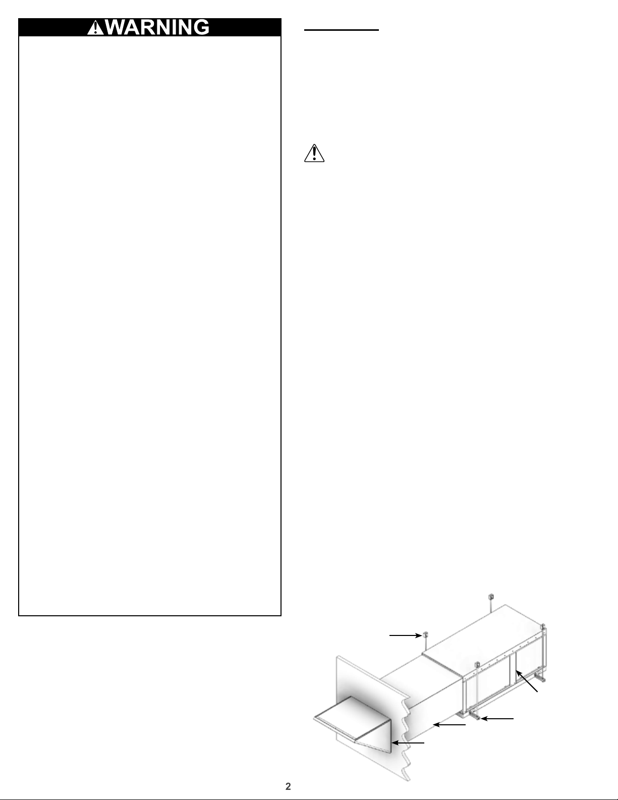
Indoor Hanging Arrangement
1. Install threaded hangers from ceiling supports.
When locating hangers, allow enough room to open
access panel(s). Two nuts must be used on the end
Hanging Mount Example
Hangers
Wiring Entry
Unit
Duct
Sealant
Supports
Page 3
3
of each threaded hanger. Ceiling supports are not
supplied.
2. Using sheet metal screws, attach the weatherhood/
thru-wall / lter section to the damper / burner
section. The ange on the weatherhood / thru-wall
/ lter section should overlap the ange on the
damper / burner section.
3. Raise the unit into place
4. Using two nuts per hanger, fasten the unit supports
to the hangers under the unit. Appropriate unit
supports, such as the optional hanging bracket kit
or c-channel and angle iron (not included) should be
used.
5. Attach ductwork to unit using self-tapping screws
NOTICE! In order to prevent the unit from swinging
and to provide a safe environment for service and
maintenance, additional measures may be needed to
secure the unit.
Good duct practices should be followed for
all ductwork. Ductwork should be installed
in accordance with SMACNA and AMCA
guidelines, NFPA 96 and any local codes.
NOTICE! When a duct work system is attached to
the inlet of the heater purge the volume of the duct
system with at least four air changes prior to an
ignition attempt.
6. Apply sealant around the perimeter of the
weatherhood to prevent water penetration and drafts
into the building.
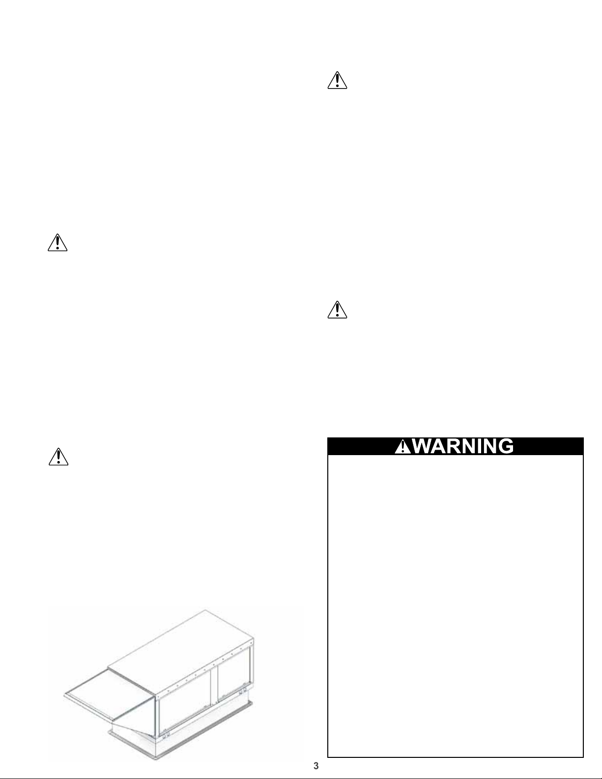
Curb Arrangement
1. Position curb on the roof. Verify that unit supports
are level, shim if necessary.
2. Attach curb to roof, ash in place
3. Attach ductwork to unit using self-tapping screws
Good duct practices should be followed for
all ductwork. Ductwork should be installed
in accordance with SMACNA and AMCA
guidelines, NFPA 96 and any local codes.
4. Apply an appropriate sealant around the perimeter
of the curb and duct adapter(s) to isolate fan
vibration and prevent water penetration
5. Use the 4 lifting lugs to lift and place unit on the
curb. A crane with a spreader bars is required.
6. NOTICE! Do not include a wood nailer. Use self-
tapping sheet metal screws to fasten the unit to the
curb support.
7. The weatherhood can now be assembled and
Curb Mount Example
attached to the unit.
8. Using an appropriate sealant, seal the seam
between the weatherhood and the unit.
Wiring
All wiring should be done in accordance with
the latest edition of the National Electric Code
ANSI / NFPA 70 and any local codes that may
apply. In Canada, wiring should be done in
accordance with the Canadian Electrical Code.
NOTICE! The equipment must be properly
grounded. Any wiring running through the unit in
the airstream must be protected by metal conduit,
metal clad cable or raceways.
NOTICE! If any of the original wire as supplied with
the heater must be replaced, it must be replaced
with type TW1 600v wire or its equivalent.
NOTICE! Field-wiring having a temperature rating
of at least 105ºC shall be used and supply circuit
wiring shall have a minimum size of 14 AWG.
NOTICE! High voltage electrical input is needed for
this equipment.
An electric disconnect switch having adequate
ampacity (see marking on the heater for
voltage and ampacity), if not provided as part
of the heater, shall be installed in accordance
with Article 430 of the National Electrical Code,
ANSI/NFPA 70.
1. The unit’s nameplate states the voltage and the
unit’s MCA. The main power lines to the unit should
be sized accordingly. The nameplate is located on
the outside of the unit on the control panel side.
2. Install eld electrical wires through the provided
Custom work
Any wiring deviations may result in personal
injury or property damage. Manufacturer
is not responsible for any damage to, or
failure of the unit caused by incorrect nal
wiring.
Manufacturer’s standard control voltage is
120 VAC. Control wire resistance should not
exceed 0.75 ohms (approximately 285 feet
total length for 14 gauge wire; 455 feet total
length for 12 gauge wire). If the resistance
exceeds 0.75 ohms, an industrial-style
plug-in relay should be wired in place of
the remote switch. The relay must be rated
for at least 5 amps and have a 120 VAC
coil. Failure to comply with these guidelines
may cause motor starters to chatter or not
pull in, resulting in contactor failures and/or
motor failures.
Page 4
4
holes.
Ground A
3 Phase, 9 Lead Motor
3 Phase, 9 Lead Motor
3. Connect the main power lines to the disconnect
switch and main grounding lug(s). Torque eld
connections to 20 in.-lbs.
4. Wire the optional convenience outlet. The
convenience outlet requires a separate 115V power
supply circuit. The circuit must include short circuit
protection which may need to be supplied by others.
Single Phase
When ground is required, attach
to ground A or B with no. 6
thread forming screw. To reverse,
T-1
T-4
interchange T-1 and T-4
Ground B
Three Phase
A complete wiring diagram is attached on
the inside of the control center door(s). It is
also available in the HMD Wiring Diagram
Supplement.
Y-Connection
Low Voltage
208/230 Volts
4
5
6
1
728
3
9
L2L
L
3
1
High Voltage
460 Volts
456
789
12
L2L
L
1
Delta-Connection
Low Voltage
208/230 Volts
7
6
1
3
L
1
3
High Voltage
9
8
5
4
3
2
L
L
3
2
12
Gas
All gas piping must be installed in accordance
with local codes, or in the absence of local
codes, in accordance with the National Fuel
Gas Code, ANSI 2223.1/NFPA 54, or the
CAN/CSA B149.1 Natural Cas and Propane
Installation Code.
Do not connect the unit to gas types other than
what is specied and do not connect the unit to gas
pressures that are outside of the pressure range
shown on the label.
When connecting the gas supply, the length
of the run must be considered in determining
the pipe size to avoid excessive pressure drop.
Refer to a Gas Engineer’s Handbook for gas
pipe capacities.
Refer to the heater rating plate for determining
the minimum gas supply pressure for obtaining
the maximum gas capacity for which this heater
is specied.
1. Determine the supply gas requirements by looking
at the unit’s nameplate on the outside of the unit on
the control center side.
2. When the supply gas pressure exceeds the maximum
gas pressure shown on the nameplate, an additional
regulator (by others) is required to reduce the
pressure. The regulator must have a listed leak
limiting device or it must be vented to the outdoors.
The regulator located inside the unit is used to adjust
the unit’s maximum output temperature.
460 Volts
789
456
3
L
L
1
2
3. If an optional vent line is located between the safety
shutoff valves it must be piped to the outdoors.
Reference the National Fuel Gas Code for
additional vent line requirements.
4. Test the system for leaks.
Operation
L
1
Line
L
2
Follow the pre start-up list before
proceeding. Follow the procedure in the
exact order that it is presented.
Failure to do so could result in serious injury
or death and damage to equipment.
Pre Start-Up:
General
1. Get: voltage & amperage meter, thermometer, micro
amp meter, u-tube manometer & tachometer.
2. Perform a gas leak check during heater start-up, to
verify the gas tightness of the heater’s components
L
3
and piping under normal operating conditions.
3. Disconnect and lock-out all power and gas.
Blower
1. Check the housing, blower, and ductwork for any
foreign objects before running the blower.
2. Rotate the fan wheel by hand and make sure no
parts are rubbing. Check the V-belt drive for proper
alignment and tension (a guide for proper belt tension
and alignment is provided in the Belt Maintenance
section).
3. Check fasteners, set screws and locking collars on
the fan, bearings, drive, motor base, and accessories
for tightness.
4. Compare the supplied voltage, hertz, and phase with
the unit and motor’s nameplate information.
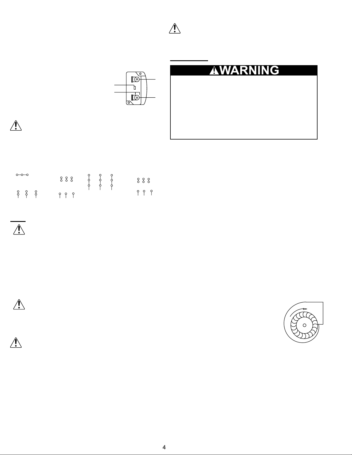
5. Open the blower access door and run
the blower momentarily to determine
the rotation. Arrows are placed on the
blower scroll to indicate the proper
direction.
NOTICE! If the blower is rotating in
the wrong direction, the unit will move
some air, but will not perform as designed. Be sure
to perform a visual inspection to guarantee the
correct blower rotation.
• To reverse the rotation on three phase units,
disconnect and lock-out the power, then interchange
any two power leads.
• To reverse the rotation on single phase units,
disconnect and lock-out the power, then rewire the
motor per the motor manufacturer’s instructions.
6. Check for unusual noise, vibration or overheating
of the bearings. Reference the Troubleshooting
section for corrective actions. Excessive vibration
Pre Start-Up
Page 5
5
may be experienced during the initial start-up. Left
unchecked, it can cause a multitude of problems
including structural and/or component failure.
Generally, fan vibration and noise is transmitted
to other parts of the building by the ductwork. To
minimize this undesirable effect, the use of heavy
canvas duct connectors is recommended.
7. Measure the motor’s voltage, amps and RPM.
Compare to the specications. Motor amps can be
reduced by lowering the motor RPM or increasing
system static pressure. Additional starters and
overloads may be provided in the make-up air
control center for optional exhaust blowers. Any
additional overloads must be checked for proper
voltage and amps.
8. Measure the unit’s air volume (cfm) and compare
it with its rated air volume. If the measured air
volume is wrong, adjust the fan’s RPM by changing/
adjusting the drive. The most accurate way to
measure the air volume is by using a Pitot traverse
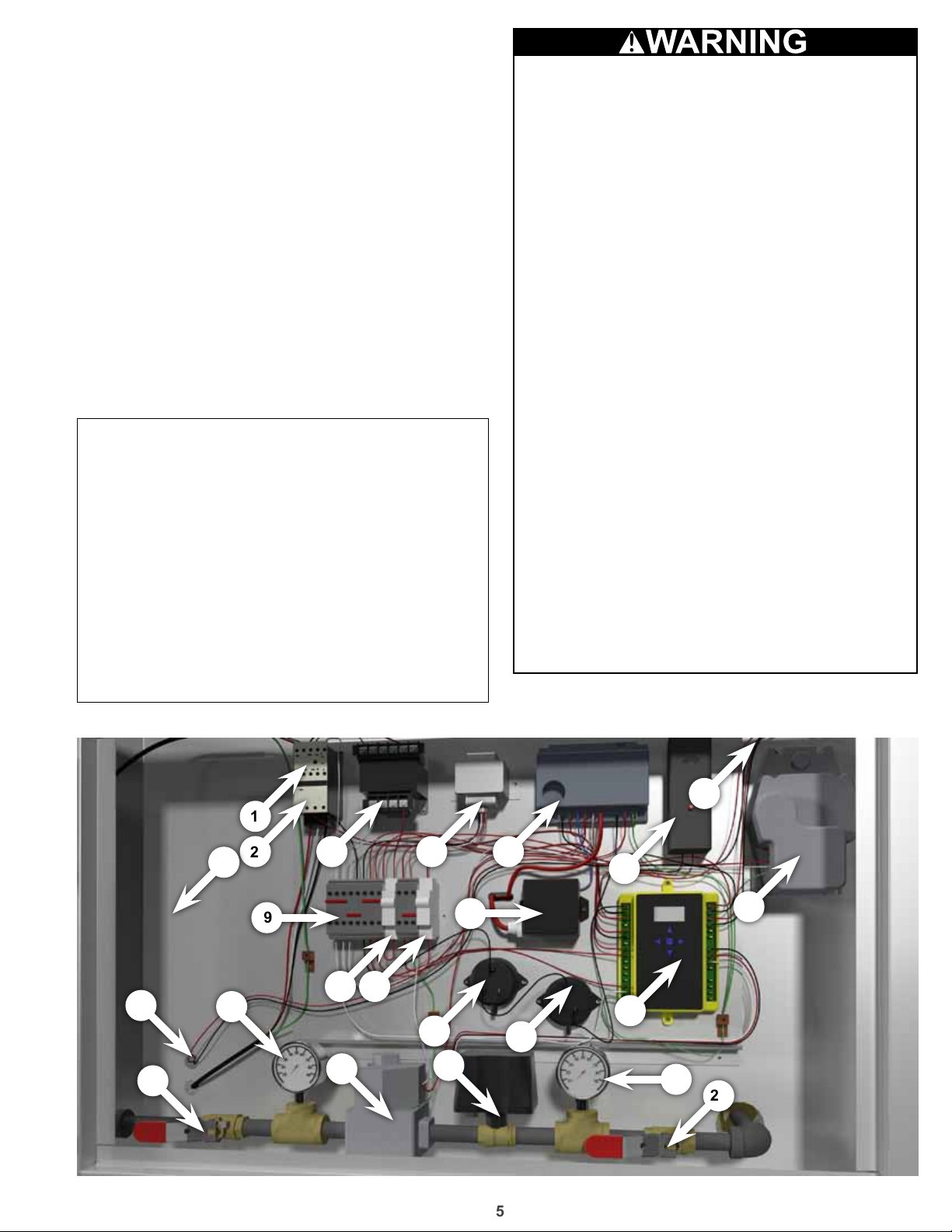
Control Panel Parts
1. Contactor
2. Overload
3. Three phase
transformer #A
4. 120 - 24v
transformer #B
5. Ignition control
6. High Temp Overload
7. Mild weather thermostat
to damper
8. Damper motor
9. Terminal blocks
10. Circuit breaker
11. Override switch
12. 120v spark ignitor
13. Pressure sensing probe
(high)
14. Pressure sensing probe
(low)
15. Temperature controller
16. Thermostat to blower
17. Safety Shut off valve
18. Pressure gauge
19. Gas valve
20. Modulating gas valve
21. Pressure gauge
22. Safety Shut off valve
23. Optional V.F.D. here
Testing Inspection
All components of this or any other gasred heating unit must be leak tested prior
to placing the unit into operation. The
factory piping has been checked for leaks
but should be rechecked due to shipping &
installation issues. The eld-installed shutoff
valve should also be checked.
A soap & water solution should be used to
perform this test.
Never test for gas leaks with a ame.
When leak testing pressures that are less
than or equal to 14 in. wc (3.5 kPa), rst
close the eld-installed shutoff valve to
isolate the unit from gas supply line.
When leak testing presures that are more
than 14 in. wc (3.5 kPa), close the eld-
installed shutoff valve, disconnect the
furnace & gas train from the gas supply line
& plug the supply line before testing.
All piping should be clean & free of any
foreign matter, which may damage the
values, regulators or burner.
Control Panel
16
17
1
2 3 4 5
23
9
10 11
18
13
19
20
12
7
6
8
15
14
21
22
Page 6

6
method downstream of the blower. Changing the air
volume can signicantly increase the motor’s amps.
If the air volume is changed, the motor’s amps must
be checked to prevent overloading the motor. To
ensure accuracy, the dampers are to be open when
measuring the air volume.
9. Adjust the settings on the optional components.
See the Control Center Layout in the Reference
section for location of optional components.
• Heating Inlet Air Sensor
Typical setting: 60-70ºF
• Building Freeze Protection
Typical setting: 45ºF
• Dirty Filter Gauge
Typical setting: Settings vary greatly for each unit.
Gas
1. Check the supply gas pressure and compare it with
the unit’s nameplate pressure requirements. Adjust
the supply regulator as needed until the supply gas
pressure is within the specied range (see below).
The nameplate is located on the outside of the unit
on the control panel side.
2. Check the settings on the optional high and low
gas pressure switches. The high pressure setting is
typically 8 inches wc (2 kPa) and the low pressure
is setting is typically 3 inches wc (0.7 kPa). The
switches are set at the factory and should not need
adjustment. Adjust the setting only if needed. The
purpose of the high and low gas pressure switches
is to automatically shut down the burner if the inlet
gas pressure is too low for the burner to safely
light, or if the manifold pressure is too high for the
burner to operate properly. Proper air velocity over
the burner is critical on direct red gas units. If the
air velocity is not within the unit specications, the
unit will not operate efciently, may have sporadic
shutdowns, and may produce excessive carbon
monoxide (CO) or other gases.
3. With all access panels in place, the fan running
and discharging 70ºF (21ºC) air, connect a U-Tube
manometer to the outer sensing probes and
measure the static pressure across the burner.
The proper static pressure should be (check CFM /
Static Pressure chart on page 8). If needed, evenly
adjust the bafes, keeping the burner centered in
the opening until the required pressure is obtained.
The pressure drop was set at the factory and may
not need adjustment. When required pressure is
obtained, be sure to reconnect the outer sensing
probes. This process may need to be repeated until
the proper pressure is achieved. This adjustment
will change the air quantity delivered by the unit
and therefore the air quantity delivered should be
rechecked. Refer to the Blower Start-Up section.
• To increase static pressure decrease the opening.
• To decrease static pressure increase the opening.
4. Monitor the unit’s actual temperature rise by placing
a thermocouple in the unit’s inlet and a second in
the discharge, three duct diameters downstream
of the burner. Send the unit to maximum ame
by changing the rotation of the motor pack from
left to right. Use a screw driver on top of modular
gas valve. While monitoring the unit’s temperature
rise, set the maximum ring rate by adjusting the
regulator until the designed temperature rise is
achieved. After setting the maximum ring rate,
reconnect the wire to the amplier. Do not set the
burner maximum ring rate based on gas pressure.
It should be set based on the unit’s designed
temperature rise shown on the label. Setting the
maximum ring rate during mild weather conditions
may cause the high limit to trip out during extreme
conditions requiring manual resetting. Gas trains
are equipped with a combined regulator valve.
Clockwise rotation increases the temperature
rise; counterclockwise rotation decreases the
temperature rise. The minimum setting for the
maximum ring rate may be higher than required.
This is acceptable, the burner will modulate as
needed. To convert from Natural Gas to LP or vice
versa follow the instructions associated with the
high re gas valve.
5. Set the operating temperature.
Maintenance - All year
V-Belt Drives
NOTICE! Do not pry belts on or off
the sheave. Loosen belt tension
until belts can be removed by
simply lifting the belts off the
sheaves. When replacing
V-belts on multiple groove
drives, all belts should
be changed to provide
uniform drive loading.
Do not install new belts
on worn sheaves. If the
sheaves have grooves
worn in them, they must be replaced before new
belts are installed.
Tolerance
Center Distance Maximum Gap
Up thru 12” 1/16”
12” up through 48 1/8”
Over 48” 1/4”
1/4 inch
1 foot
Page 7

7
NOTICE! Premature or frequent belt failures can
be caused by improper belt tension, or misaligned
sheaves. Abnormally high belt tension or drive
misalignment will cause excessive bearing loads
and may result in failure of the fan and/or motor
bearings. Abnormally low belt tension will cause
squealing on start-up, excessive belt utter,
slippage, and overheated sheaves.
1. V-belt drives must be checked on a regular basis for
wear, tension, alignment, and dirt accumulation.
2. Check the tension by measuring the deection in the
belt as shown here.
3. Check the alignment by using a straight edge across
both sheaves. The drawings below show where to
measure the allowable gap for the drive alignment
tolerance. All contact points (indicated by WXYZ)
are to have a gap less than the tolerance shown in
the table. When the pulleys are not the same width,
the allowable gap must be adjusted by half of the
difference in width.
Snow Accumulation
Clear snow away from roof mounted units. Keep the
snow clear of the intake and access doors.
Motors
Motor maintenance is generally limited to cleaning and
lubrication (where applicable). Cleaning should be limited
to exterior surfaces only. Removing dust and grease build-
up on the motor assures proper motor cooling.
Motors supplied with grease ttings should be greased
in accordance with the manufacturer’s recommendations.
Greasing motors is only intended when ttings are
provided. Many motors are permanently lubricated,
requiring no additional lubrication.
NOTICE! Do not allow water or solvents to enter
the motor or bearings. Motors and bearings should
never be sprayed with steam, water or solvents.
Relubrication Intervals
NEMA Frame Size
Service
Conditions
Up to and
including 184T
1800
RPM
and
less
Over
1800
RPM
213T-365T 404T and larger
1800
RPM
and
less
Over
1800
RPM
1800
RPM
and
less
Over
1800
RPM
size. The instructions provided in this manual and those
provided by the bearing manufacturer will minimize any
bearing problems.
Lubricate bearings prior to periods of extended
shutdowns or storage and rotate shaft monthly to aid in
corrosion prevention. If the fan is stored more than three
months, purge the bearings with new grease prior to start-
up.
Motors are provided with a polyurea mineral oil NGLI #2
grease. All additions to the motor bearings are to be with
a compatible grease such as Exxon Mobil Polyrex EM and
Chevron SRI.
The above intervals should be reduced to half for vertical
shaft installations.
Relubrication Intervals
RPM Temp °F Greasing Interval
Up to 1000
1000 to 3000
Over 3000
Any Speed < -30 Consult Factory
Any Speed > 200 1 week
-30 to 120 6 months
120 to 200 2 months
-30 to 120 3 months
120 to 200 1 month
-30 to 120 1 month
120 to 200 2 weeks
Filter
Filter maintenance is generally limited to cleaning and
replacement.
If aluminum mesh lters are installed, they can be
washed in warm soapy water.
An adhesive spray can be added to aluminum mesh
lters to increase their efciency.
If disposable lters are installed, they can be checked
by holding up to a light source. If light cannot pass through
the lter, it should be replaced.
When reinstalling lters, be sure to install them with the
airow in the correct direction. An airow direction arrow is
located on the side of the lters.
Replacement lters should be from the same
manufacturer and the same size as the original lters
provided with the unit.
Maintenance - Beginning of season
Start-Up
3 yrs.
Standard
1 yr.
Severe
6
months
3
months
2 yrs.
1 yr.
6
months
3
months6 months1 months
1 yr.
3
months
Wheels
Wheels require little attention when moving clean air.
Occasionally oil and dust may accumulate on the wheel
causing imbalance. When this occurs the wheel and
housing should be cleaned to assure proper operation.
Bearings
The bearings are carefully selected to match the
maximum load and operating conditions of the specic fan
Repeat the Blower Start-Up Step #5 and Direct Gas
Start-Up Steps #1, #2 and #3. This will ensure that the gas
and air are set properly before the heating season begins
and should lead to trouble free operation all winter.
High Limit
The high limit switch may have tripped over the summer;
it should be checked and reset if necessary.
Burner
Inspect the burner for accumulation of scales on both the
upstream and downstream sides of the mixing plates. Any
scaling or foreign material should be removed with a wire
brush.
Visually check that all holes in the mixing plates are
clear. If any burner ports are plugged (even partially), clear
them with a piece of wire or another appropriate tool.
Page 8

8
Do not enlarge burner ports when clearing a blockage,
performance could be affected.
Replace or tighten any loose or missing fasteners on
the mixing plates. Always use zinc plated or stainless
steel fasteners.
Inspect and clean the ame and spark rod. Occasional
replacement of the ame rod and spark rod may be
necessary to ensure optimum unit performance.
Flame rods can last many years, but because of
thermal expansion of the porcelain, ame rods can fail
over time.
Gas Train
The gas connections, joints and valves should be
checked annually for tightness. Apply a soap and water
solution to all piping; watch for bubbling which indicates a
leak. Other leak testing methods can be used.
CFM / Static Pressure chart
Model # Low CFM Low SP High CFM High SP
2400 680 0.05 2400 0.94
3400 2000 0.2 3400 1
4100 3000 0.35 4100 1.1
Parts
To replace parts, contact a COOK representative.
Page 9

9
Blower does not operateTroubleshooting
Is the proper power
supply at the main
disconnect?
Yes
Is there 120 VAC
between terminals X2 &
X1 on transformer #A?
Yes
Is there 120 VAC between
terminal block #2 &
circuit breaker terminal 2?
No
No
No
1. Compare the supplied voltage, hertz, and phase with the motor’s
nameplate information.
2. Make sure disconnect switch is on.
Replace 480-120v transformer #A
1. Make sure supply switch is on.
Yes
Is there 120 VAC
between terminal blocks
1 & 5?
Yes
Is there 120 VAC
between across A1 &
A2 on supply contactor?
Yes
1. Replace fan belt, if broken.
2. Repair or replace motor or capacitor if needed.
3. Repair motor fuse if needed.
4. Repair or replace one or more of the motor
wiring legs, if needed.
No
No
1. Correct supply fan overload if tripped. Check for proper voltage, amps
and RPMs.
2. Check optional exhaust fan interlocks
1. Install the optional damper limit switch, if not installed. If holding, wait
for actuator to fully open or adjust the limit switch.
2. Repair or replace fan relay if not energizing. Check for loose
connection.
At this time the supply contactor
should pull in, passing power to the
supply motor & blower should start.
Refer to the control panel parts list when troubleshooting.
Page 10

10
Troubleshooting
Motor overamps
Is the air volume too
high?
No
Is the static pressure
lower than rated?
No
Is the blower rotating in
the wrong direction? If
the blower is rotating in
the wrong direction, the
unit will move some air,
but will not perform as
designed.
Yes
Yes
Yes
Adjust drive &
increase external
pressure. as needed.
Adjust drive to
reduce rpm as
needed.
To reverse the rotation on three phase units, disconnect and lock-out the
power, then interchange any two power leads.
To reverse the rotation on single phase units, disconnect and lock-out the
power, then rewire the motor per the motor manufacturer’s instructions.
Measure the unit’s air volume
(cfm) and compare it with its
rated air volume. If the measured
air volume is wrong, adjust the
fan’s RPM by changing/adjusting
the drive. The most accurate
way to measure the air volume
is by using a Pitot traverse
method downstream of the
blower. Changing the air volume
can signicantly increase the
motor’s amps. If the air volume
is changed, the motor’s amps
must be checked to prevent
overloading the motor. To ensure
accuracy, the dampers are to be
open when measuring the air
volume.
No
Is the motor voltage
correct?
Yes
Is the motor horse
power too low?
No
Shorted winding on the
motor?
No
Yes
Yes
Compare the supplied voltage, hertz, and phase with the unit and
motor’s nameplate information. Correct as needed.
Replace motor.
Consult factory.
No
Refer to the control panel parts list when troubleshooting.
Page 11

11
Troubleshooting Insufcient airow
Are the dampers not
fully open? This may
take several minutes.
No
Are the system static
losses too high?
No
Is the blower speed too
low?
No
Yes
Yes
Yes
Adjust dampers or replace damper/actuator as needed.
Reduce loss by improving ductwork.
Measure the unit’s air volume (cfm)
and compare it with its rated air
volume. If the measured air volume
is wrong, adjust the fan’s RPM by
changing/adjusting the drive. The
most accurate way to measure
Adjust the drives as needed.
the air volume is by using a Pitot
traverse method downstream of the
blower. Changing the air volume
can signicantly increase the
motor’s amps. If the air volume is
changed, the motor’s amps must
be checked to prevent overloading
the motor. To ensure accuracy,
the dampers are to be open when
measuring the air volume.
Are the lters dirty or
clogged?
No
Are there leaks in the
ductwork?
No
Is the belt slipping?
No
Yes
Yes
Yes
Replace / clean the lters as needed.
Repair ductwork.
1. Replace or tighten as needed.
2. Install automatic belt tensioner if possible.
Refer to the control panel parts list when troubleshooting.
Consult factory.
Page 12
12
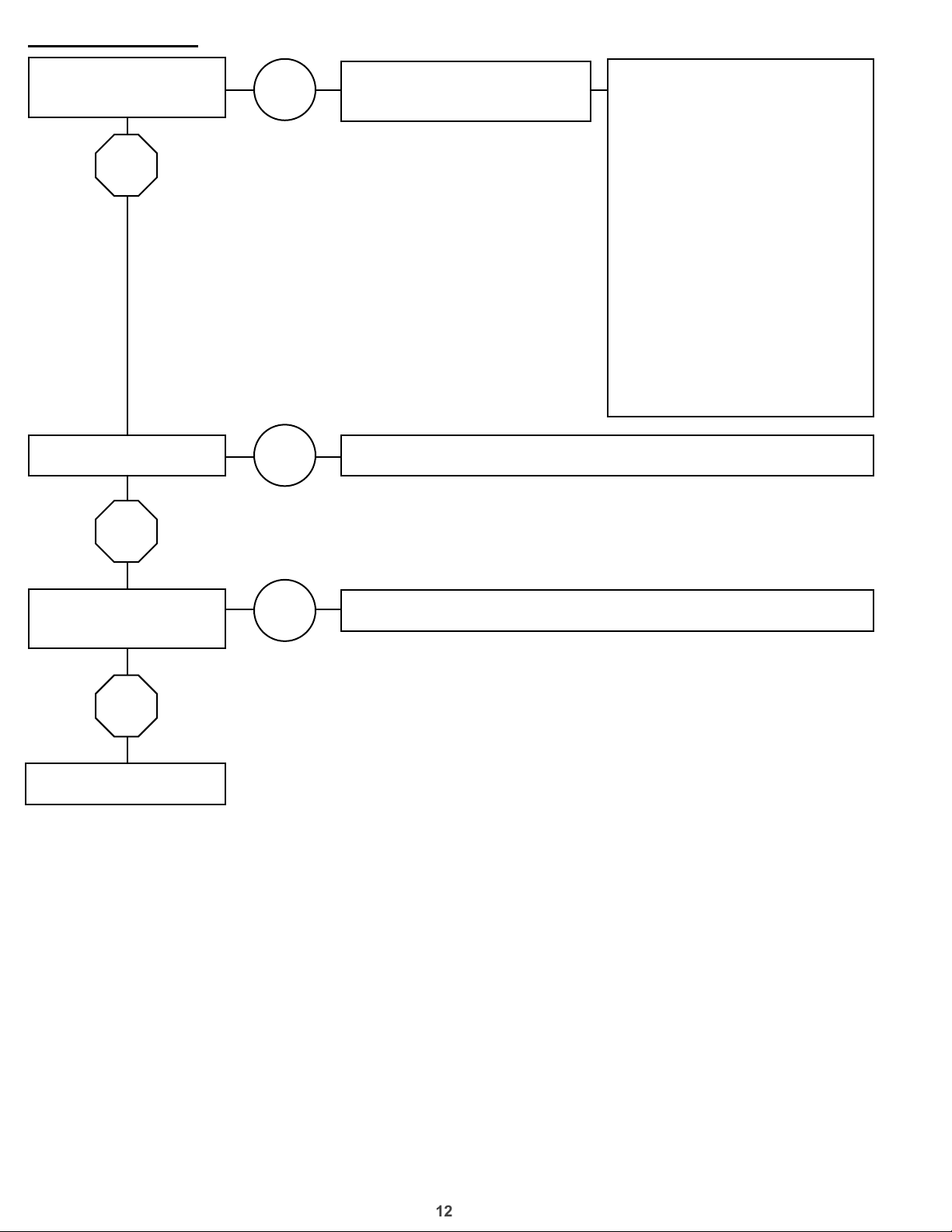
Troubleshooting
Too much airow
Is the blower speed too
high?
No
Are the lters missing?
Yes
Yes
Adjust drive & decrease
external pressure. as needed.
Install lters.
Measure the unit’s air volume
(cfm) and compare it with its
rated air volume. If the measured
air volume is wrong, adjust the
fan’s RPM by changing/adjusting
the drive. The most accurate
way to measure the air volume
is by using a Pitot traverse
method downstream of the
blower. Changing the air volume
can signicantly increase the
motor’s amps. If the air volume
is changed, the motor’s amps
must be checked to prevent
overloading the motor. To ensure
accuracy, the dampers are to be
open when measuring the air
volume.
No
Is there insufcient
external pressure?
No
Consult factory.
Yes
Increase external static pressure.
Refer to the control panel parts list when troubleshooting.
Page 13

13
Troubleshooting
Excessive noise or vibration
Is the belt loose or
damaged?
No
Are the sheave aligned?
Yes
Is the wheel
unbalanced?
No
Yes
No
Yes
1. Replace or tighten as needed.
2. Install automatic belt tensioner if possible.
Align sheaves.
Clean or replace the wheel.
Are the lters dirty /
clogged?
No
Are the bearings worn or
do they need lubrication?
No
At this time the noise or vibration
should be at acceptable levels
Yes
Yes
Clean or replace lters as needed.
Lubricate or replace bearings as needed.
Refer to the control panel parts list when troubleshooting.
Page 14

14
Troubleshooting
Heater does not attempt to light. Heater attempts to light, but no ame
Is there 120 VAC between
terminal block #2 &
circuit breaker terminal 2?
Yes
Is there 24 VAC
between terminal blocks
9 & 10?
Yes
Is there 120 VAC between
terminal block #10 & high
temp limit switch #2?
No
1. Make sure supply switch is on.
Replace 24 VAC transformer.#b
No
Correct / replace high temp overload switch.
No
Yes
Is there continuity
between terminal block
#4 & low pressure switch
normal open?
Yes
Consult factory
No
1. With all access panels in place, the fan running and discharging 700F
(210C) air, connect a U-Tube manometer to the outer sensing probes
(see below) and measure the stac pressure across the burner. The
proper stac pressure should be (check CFM / Static Pressure chart
on page 8). If needed, evenly adjust the baes, keeping the burner
centered in the opening unl the required pressure is obtained. The
pressure drop was set at the factory and may not need adjustment.
When required pressure is obtained, be sure to reconnect the outer
sensing probes. This process may need to be repeated unl the proper
pressure is achieved. This adjustment will change the air quanty
delivered by the unit and therefore the air quanty delivered should be
rechecked. Refer to the Blower Start-Up secon.
2. To increase the stac pressure decrease the opening.
3. To decrease the stac pressure increase the opening.
Refer to the control panel parts list when troubleshooting.
Page 15

15
Troubleshooting
Is the inlet gas pressure
between the min and
max?
Yes
Attempts to light, with visible spark, but no ame
Check the supply gas pressure and compare it with the unit’s nameplate
pressure requirements. Adjust the supply regulator as needed until
No
the supply gas pressure is within the specied range (see below). The
nameplate is located on the outside of the unit on the control panel side.
Is there air in the gas
line?
No
Is the pressure drop
across the burner
correct? (check chart
on page 8)
Yes
Is there still not a proper
spark?
Yes
No
No
Purge the air.
With all access panels in place, the fan running and discharging 70ºF
(21ºC) air, connect a U-Tube manometer to the outer sensing probes
(see below) and measure the static pressure across the burner. The
proper static pressure should be (check CFM / Static Pressure chart
on page 8). If needed, evenly adjust the bafes, keeping the burner
centered in the opening until the required pressure is obtained. The
pressure drop was set at the factory and may not need adjustment.
When required pressure is obtained, be sure to reconnect the outer
sensing probes. This process may need to be repeated until the proper
pressure is achieved. This adjustment will change the air quantity
delivered by the unit and therefore the air quantity delivered should be
rechecked. Refer to the Blower Start-Up section.
To increase the static pressure decrease the opening.
To decrease the static pressure increase the opening.
The wires may be switched. Uncross the spark wires.
Make sure the spark gap is .062 in.
Replace spark the plug.
Yes
Consult factory
Refer to the control panel parts list when troubleshooting.
Page 16

16
Warranty
Loren Cook Company warrants that your Loren
Cook fan was manufactured free of defects in
materials and workmanship, to the extent stated
herein. For a period of one (1) year after date of
shipment, we will replace any parts found to be
defective without charge, except for shipping costs
which will be paid by you.
This warranty is granted only to the original
purchaser placing the fan in service.
This warranty is void if the fan or any part thereof
has been altered or modied from its original design
or has been abused, misused, damaged or is in
worn condition or if the fan has been used other
than for the uses described in the company manual.
This warranty does not cover defects resulting from
normal wear and tear.
To make a warranty claim, notify Loren Cook
Company, General Ofces, 2015 East Dale Street,
Springeld, Missouri 65803-4637, explaining in
writing, in detail, your complaint and referring to the
specic model and serial numbers of your fan. Upon
receipt by Loren Cook Company of your written
complaint, you will be notied, within thirty (30) days
of our receipt of your complaint, in writing, as to the
manner in which your claim will be handled. If you
are entitled to warranty relief, a warranty adjustment
will be completed within sixty (60) business days of
the receipt of your written complaint by Loren Cook
Company.
This warranty gives only the original purchaser
placing the fan in service specically the right. You
may have other legal rights which vary from state to
state.
For fans provided with motors, the motor
manufacturer warrants motors for a designated
period stated in the manufacturer’s warranty.
Warranty periods vary from manufacturer to
manufacturer. Should motors furnished by
Loren Cook Company prove defective during the
designated period, they should be returned to the
nearest authorized motor service station. Loren
Cook Company will not be responsible for any
removal or installation costs.
Service Contacts
Dealer
Installation
Contractor:
Service
Contractor:
Date of Installation:
Name:
Address:
Phone:
Name:
Address:
Phone:
Name:
Address:
Phone:
Corporate Ofces 2015 E. Dale Street Springeld, MO 65803
Phone 417-869-6474 Fax 417-862-3820 lorencook.com
HMD IOM Manual - Feb 2013
 Loading...