

Page 1

®
INSTALLATION, OPERATION AND MAINTENANCE MANUAL
This publication contains the installation, operation and
maintenance instructions for standard units of the GI/GR:
Gravity Ventilators.
Carefully read this publication and any
supplemental documents prior to any
installation or maintenance procedure.
Loren Cook catalog, Gravity Ventilation, provides addi-
tional information describing the equipment, unit perfor-
mance, available accessories and specication data.
For additional safety information, refer to AMCA Publica-
tion 410-96, Safety Practices for Users and Installers of
Industrial and Commercial Fans.
All of the publications listed above can be obtained from:
• lorencook.com
• info@lorencook.com
• 417-869-6474 ext. 166
For information and instructions on special equipment,
contact Loren Cook Company at 417-869-6474.
Receiving and Inspection
Immediately upon receipt of a GI/GR unit, carefully in-
spect it for damage and shortage.
• Check dampers (if supplied) for free operation of moving parts.
• Record on the Delivery Receipt any visible sign of damage.
Handling
Lift the unit by the lifting lugs (refer to Figure 4).
NOTICE! Never lift by the hood or end panels.
Storage
If the unit is stored for any length of time prior to installation, store it in its original shipping crate and protect it from
dust, debris and the weather.
Installation
Standard Units
Standard units not requiring knock down are shipped
fully assembled and ready for installation.
GI/GR
Gravity Vents
The attachment of roof mounted fans to the roof curb as
well as the attachment of roof curbs to the building structure must exceed the structural requirements based on the
environmental loading derived from the applicable build-
ing code for the site. The local code ofcial may require
variations from the recognized code based on local data.
The licensed engineer of record will be responsible for
prescribing the correct attachment based on construction
materials, code requirements and environmental effects
specic to the installation.
Failure to follow these instructions could result in death or
serious injury.
Knockdown Units
All knocked down units are factory pre-assembled and
then disassembled for shipping. Reassemble by aligning
holes and bolting together. Parts are marked as to allow
for ease of reassembly.
Reassembling the hood is best done from the underneath side. To work on the hood it is recommended to turn
the hood upside down on two wooden four by fours, this
will prevent it from rocking during assembly. Attach the
hood sections together by the overlapping joining seams
(see Figure 5). Make sure the upper sean is overlapping
the lower seam along their entire length. A slight tap with a
rubber mallet or dead blow hammer maybe required. Align
holes and use the provided section rail splice and bolts to
secure the hood section(s) together (see Figure 3).
For units with birdscreen, rst completely assemble the
hood. Then fasten birdscreen securely to the inside of the
section rail, (see Figure 1), using speed screws (A) and
washer (B) stretching the birdscreen (C) as tight as possible. For units with aluminum birdscreen, the washers are
replaced with 1” aluminum strips at the factory. On units
with lters and birdscreen, the bird screen should extend
across the throat, not hindering the lter placement (see
Figure 4).
For units with a two piece mounting channel, insert the
mounting channel splice between the two pieces of the
mounting channel, aligning the holes (see Figure 3). Fasten the three pieces of the mounting channel assembly to
the base using the bolts and nuts provided.
For units with multiple base sections: securely fasten the
base sections through the base section splice brackets
welded to the base sections using the bolts and nuts provided (see Figure 3). To eliminate the possible egress of
water through the base splices, caulking is recommended.
1 B51116-002GI/GR IO&M
Page 2
To attach the base and hood sections: set the assembled hood on the assembled base, aligning the mounting
bracket holes with the holes in the section rails. Units with
support angles require the support angles to be bolted to
the base, using the bolts and nuts provided.
Figure 1
Section RailHood Panel
C
B
A
Throat
Filters
Filters are installed between the base and the hood pan-
els (see Figure 4). The lters should come in two sizes.
One size ts between the end panel and the base. The
other size is mounted between the base and the section
rail. Filter inspection and cleaning intervals can vary from
once a week to twice per year depending on contaminant
present and acceptable pressure drops across the lter.
Under most conditions lters may be cleaned with hot wa-
ter and a mild soap solution (such as dish washing liquid)
or steam. Some caustic cleaners will damage the lter. If
in doubt, please consult the factory for a compatibility list.
High pressure spray washers should be limited to 2,000
PSI operating pressure. Every attempt should be made to
remove the contaminants from the lter in a “backwash”
ow (NOTE: airow arrow on the lter frame). Once the
lter is dry, it may be returned to the appropriate lter racks
in the same orientation (airow direction) as they were re-
moved.
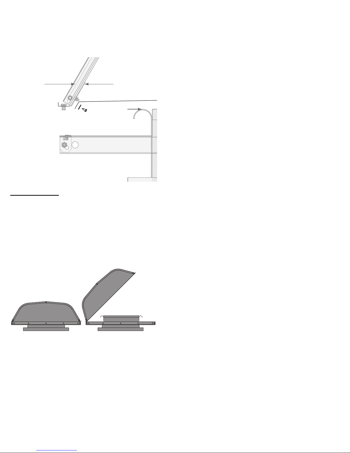
Maintenance
Hood Access
To access the throat of the unit, take the entire hood off
by removing the bolts and attaching the mounting bracket
to the mounting channels (see Figure 4). GR units with
less than a 73” throat length and GI units with less than a
61” throat length can be hinged. Hinging is accomplished
by removing the bolts on one side and loosening the two
bolts (refer to Figure 2) on the other side. Care should be
taken when hinging the hood, especially in high wind conditions.
Figure 2
2GI/GR IO&M B51116-002
Page 3

Section Rail
Mounting Channel Splic
Cross section of the end peice
Cross section of the hood panel
Figure 3
Support Angle
Mounting Channel
Hood Section
Figure 4
e
Hood Panel
End Panel
Base / Throat
Section Rail Splice
Base Splice
Hinged bolt
Lifting lug
Filter retaining clip
Filter
Mounting rail
3 B51116-002GI/GR IO&M
Page 4

Parts List
Part No. Description
1 Hood Panel
2 End Panel
3 Section Rail
4 Mounting Bracket - Left
5 Mounting Bracket - Right
6 Mounting Rail
7 Base / Throat
8 Self-Tapping Screw
9 Wizzbolt
10 Wizznut
A Self Tapping Screw
B Flat Washer
C Birdscreen
See Figure 1,
page 2
Figure 5
1
For replacement hood sections (not individual hood panels)
please indicate which open end extrusion is required: (A) the
top extrusion or (B) the bottom extrusion. For replacement
middle hood sections the extrusion designation is not required.
8
3
9
10
4
10
Standard Assembly
2
9
5
10
7
9
6
8
Limited Warranty
Loren Cook Company warrants that your Loren Cook fan was manufactured free of defects in materials and workmanship, to the extent stated herein.
For a period of ve (5) years after date of shipment, we will replace any parts found to be defective without charge, except for shipping costs which will be
paid by you. This warranty is granted only to the original purchaser placing the fan in service. This warranty is void if the fan or any part thereof has been
altered or modied from its original design or has been abused, misused, damaged or is in worn condition or if the fan has been used other than for the
uses described in the company manual. This warranty does not cover defects resulting from normal wear and tear. To make a warranty claim, notify Loren
Cook Company, General Ofces, 2015 East Dale Street, Springeld, Missouri 65803-4637, explaining in writing, in detail, your complaint and referring
to the specic model and serial numbers of your fan. Upon receipt by Loren Cook Company of your written complaint, you will be notied, within thirty
(30) days of our receipt of your complaint, in writing, as to the manner in which your claim will be handled. If you are entitled to warranty relief, a warranty
adjustment will be completed within sixty (60) business days of the receipt of your written complaint by Loren Cook Company. This warranty gives only
the original purchaser placing the fan in service specically the right. You may have other legal rights which vary from state to state.
Corporate Ofces: 2015 E. Dale St. Springeld, MO 65803
Phone 417-869-6474 | Fax 417-862-3820 | lorencook.com
March 2017
4GI/GR IO&M B51116-002
 Loading...