

COOK Gemini 600, Gemini 200, Gemini 300, Gemini 500, Gemini 700 Installation, Operation And Maintenance Manual
...Page 1
®
INSTALLATION, OPERATION AND MAINTENANCE MANUAL
This publication contains the installation, operation and
maintenance instructions for standard units of the Gemini:
Ceiling and Cabinet Fans.
Carefully read this publication and any
supplemental documents prior to any
installation or maintenance procedure.
Loren Cook catalog, Gemini, provides additional infor-
mation describing the equipment, fan performance, avail-
able accessories and specication data.
For additional safety information, refer to AMCA Publica-
tion 410-96, Safety Practices for Users and Installers of
Industrial and Commercial Fans.
All of the publications listed above can be obtained from:
• lorencook.com
• info@lorencook.com
• 417-869-6474 ext. 166
For information and instructions on special equipment,
contact Loren Cook Company at 417-869-6474.
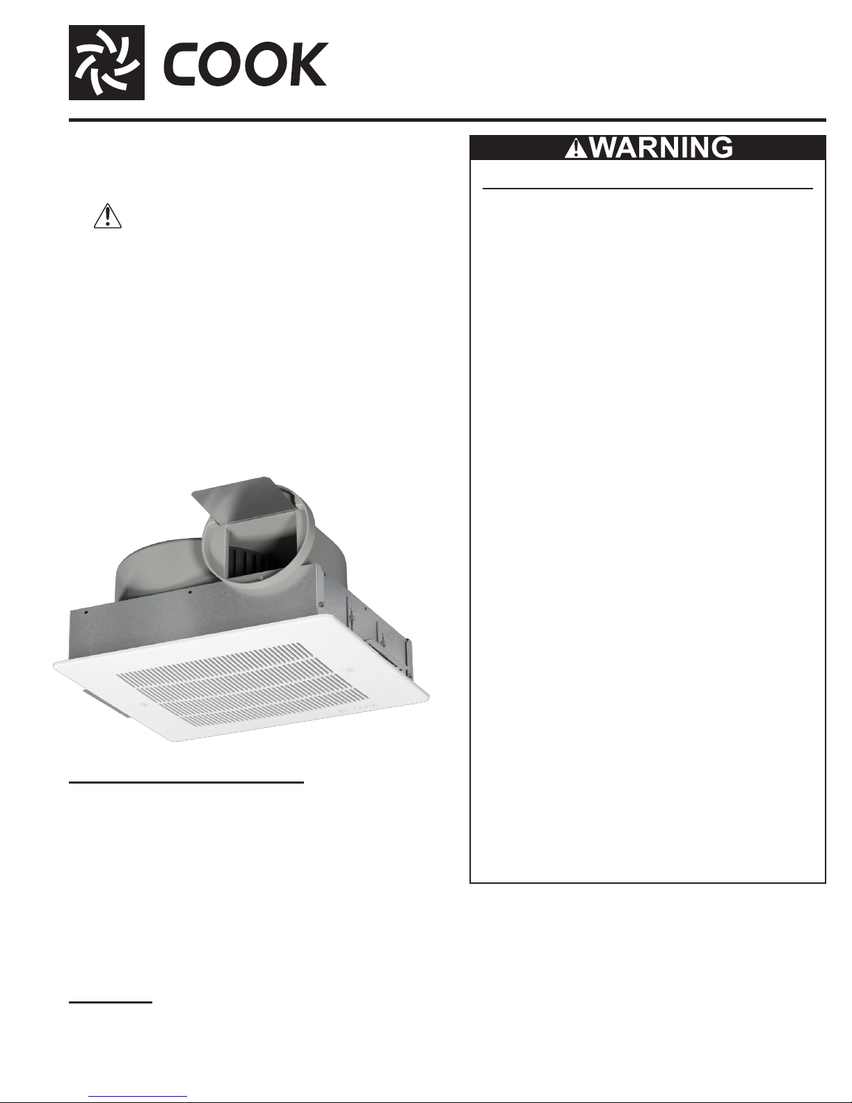
GEMINI
Ceiling and Cabinet Fans
Rotating Parts & Electrical Shock Hazard:
Fans should be installed and serviced by qualied personnel only.
Disconnect electric power before working on unit (prior to
removal of guards or entry into access doors).
Follow proper lockout/tagout procedures to ensure the unit
cannot be energized while being installed or serviced.
A disconnect switch should be placed near the fan, so
power can be swiftly turned off in case of an emergency.
This will also allow maintenance personnel to have complete control of the power source.
Grounding is required. All eld-installed wiring must be
completed by qualied personnel. All eld installed wiring
must comply with National Electric Code (NFPA 70) and all
applicable local codes.
Gemini 100
Receiving and Inspection
Carefully inspect the fan and accessories for any
damage and shortage immediately upon receipt of fan.
• Turn the wheel by hand to ensure it turns freely and does
not bind.
• Inspect dampers (if included) for free operation of all
moving parts.
• Remove mounting brackets from packing insert & install
mounting brackets (Gemini 100 only).
• Remove shipping tape.
• Record on the Delivery Receipt any visible sign of
damage.
Fans and blowers create pressure at the discharge and
vacuum at the inlet. This may cause objects to get pulled
into the unit and objects to be propelled rapidly from the
discharge. The discharge should always be directed in a
safe direction and inlets should not be left unguarded. Any
object pulled into the inlet will become a projectile capable
of causing serious injury or death.
When air is allowed to move through a non-powered fan,
the impeller can rotate. This is referred to as windmilling.
This unexpected rotation of components can cause a hazardous condition. Impellers should be blocked in position
or air passages blocked to prevent draft prior to working
on fans.
Friction and power loss inside rotating components can
cause them to be a potential burn hazard. All components
should be approached with caution and/or allowed to cool
before contacting them for maintenance.
Under certain lighting conditions, rotating components
may appear stationary. Components should be veried to
be stationary in a safe manner, before they come into contact with personnel, tools or clothing.
Failure to follow these instructions could result in death or
serious injury.
Handling
Lift fan by grasping the outside housing (cabinet) or by
the blower mounting brace. Never lift by the shaft or motor.
1GEMINI IO&M B51111-002
Page 2
Storage
6
s
atte
G
If the fan is stored for any length of time prior to
installation, store it in its original shipping crate and protect
it from dust, debris and the weather.
Installation
Motor Installation
All Gemini units are shipped with motors mounted at the
factory.
Gemini 100 Inline to Ceiling Conversion
The Gemini 100 series can be converted from inline
to ceiling by ordering the Inline to Ceiling Conversion Kit
from Loren Cook Company (Part Number 797180). The kit
includes all parts required, plus detail instructions on how
to convert the Gemini 100.
Gemini 100 Ceiling to Inline Conversion
The Gemini 100 series can be eld converted from
ceiling to inline by following these steps:
1. Remove and discard the inlet box end plate.
2. Install the inline cover panel with sheet metal screws
as shown on the following page. Ceiling to Inline
Conversion Kit can be ordered from Loren Cook
Company (Part Number 797181), or fabricate the
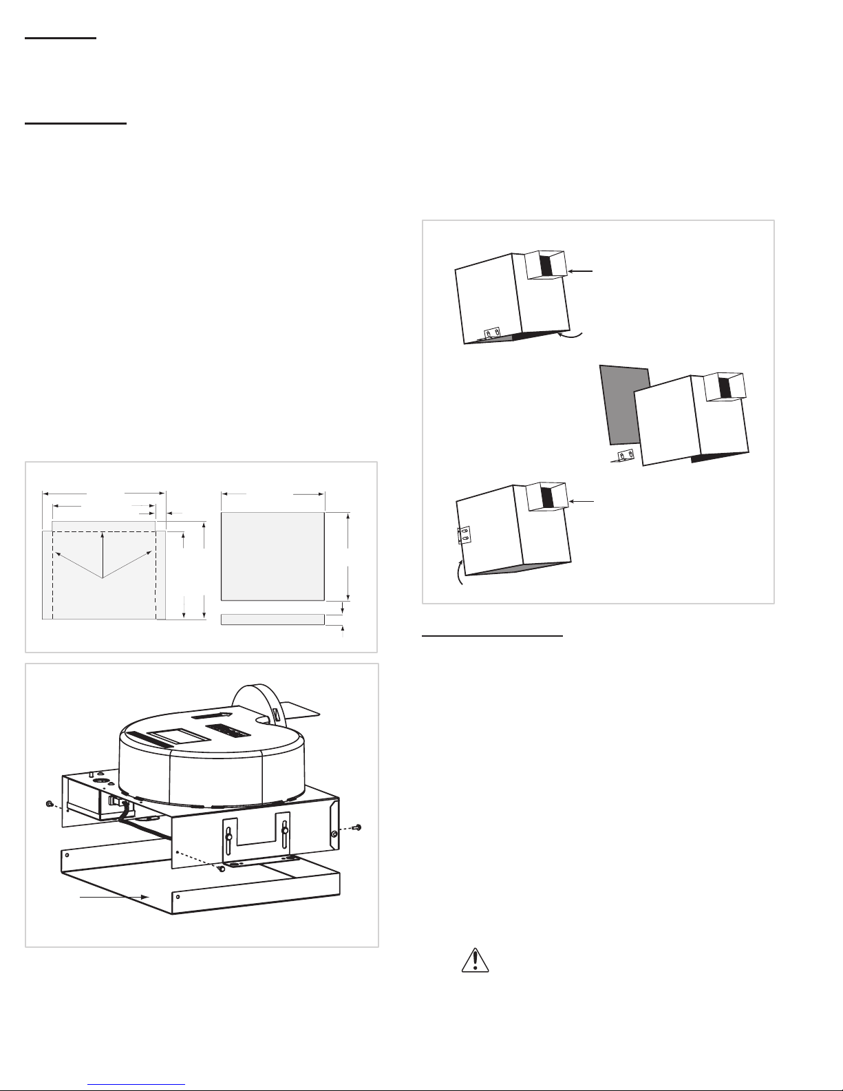
required part using the following two sketches.
a. Galvanized Steel
16-3/4
13-15/16
18
14-1/16
1-3/8
Direction of Discharge (200–900 Series)
Discharge direction can be converted from right angle to
straight line, without a kit, by swapping outer panel and the
inlet/grille: See Figure 1.
1. Remove the side panel, mounting brackets (2) and
grille (if present).
2. Place the side panel where the inlet/grille had been.
Place the mounting brackets on the edge where the
side panel had been. Holes are pre-punched for this
procedure.
3. Rotate unit so that the outlet is on top.
Figure 1
Start
Outlet
Inlet
Remove Parts
x2
Replace Parts
Outlet
Bend up at 90o
Flat P
Inline
Cover
Panel
12
Inlet
1. Use the mounting bracket slots to lower the unit
rn
11-15/16
(Inches)
13-5/16
Finished View
1-7/1
Fan Installation
housing by a distance equal to the ceiling thickness.
Refer to Figure 2.
2. Raise the unit, as needed to accommodate acces-
sories and options: With optional lter, raise unit 3/8”.
For both lter and deluxe aluminum grille options,
raise unit 7/8” to compensate for 1/2” grate protrusion of grille. If lter is not present: the grate on the
aluminum grille will t inside of the unit (except sizes
160 & 180). Other grilles have no protrusion and t
ush with the fan.
3. Fasten duct work to the outside of the duct collar
(damper frame) using sheet metal screws and foil
tape. Make sure sheet metal screws are placed
where they do not interfere with damper operation.
4. Fasten the housing to the bottom of the joists through
the holes provided in the mounting bracket.
For Ceiling Radiation Damper Installation
see separate document, “Gemini/CRD
Installation Supplement.”
2GEMINI IO&M B51111-002
Page 3
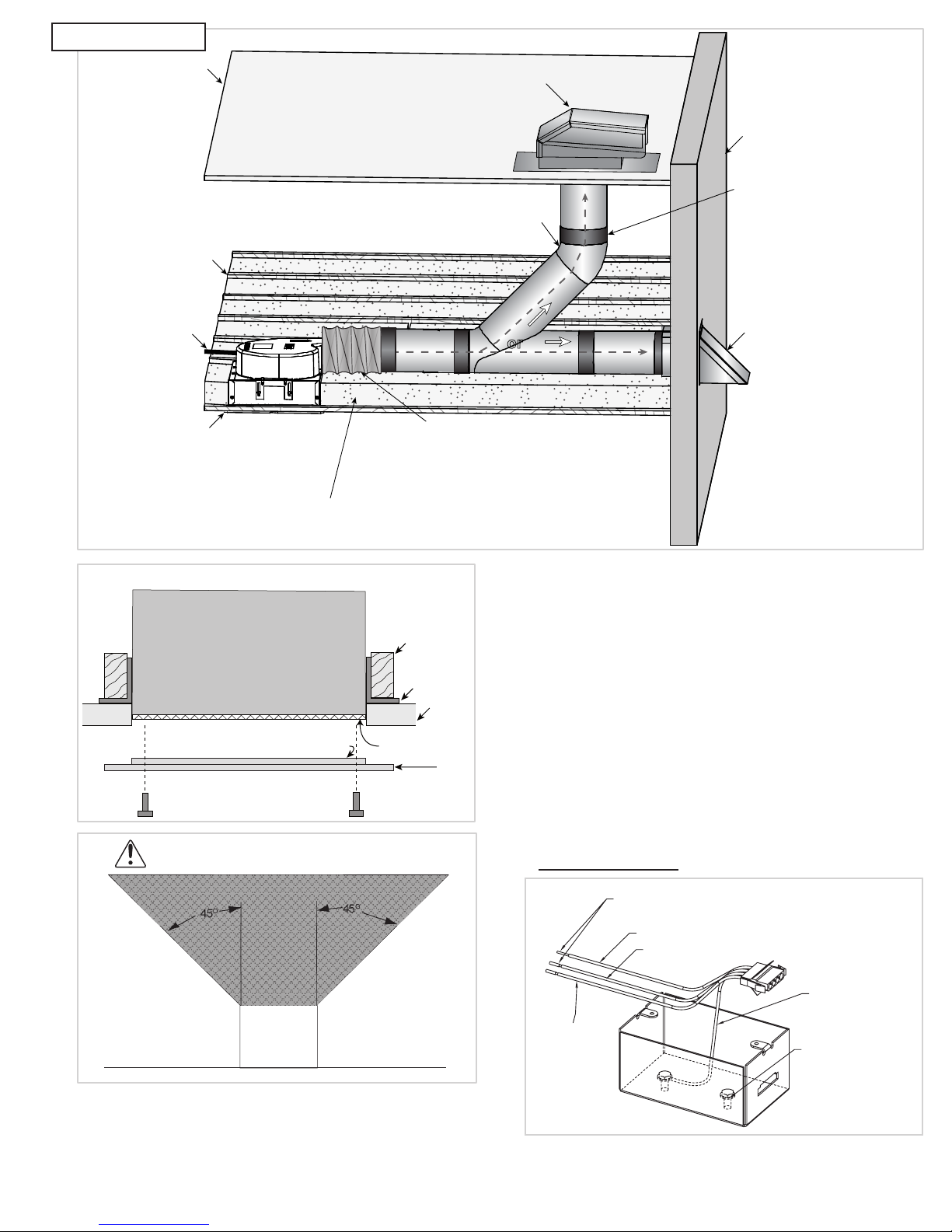
Mounting
Filter (optional)
Ceiling
Grille
Roof
Power
cord
Seal around the
unit with caulk.
Typical Installation
r
Roof jack with damper
or roof cap
Exterior
Wall
Figure 2
6” round duct. Insulated duct will help
absorb vibration. Use the shortest runs
Joists
Insulation around unit.
Also, cover the fan with insulation.
Unit Housing
Grate Protrusion (aluminum grille only)
possible & long radius elbows.
or
Short (1’) piece of flexible duct
will absorb vibration & noise.
carrying capacity of wires) is in accordance with the motor
nameplate. Refer to Wiring Diagrams.
Joists
Bracket
source.
for single speed operation, using an FSC to vary speed if
required. Do not wire to more than two leads.
Use foil tape
on the joints
to ensure a
good seal.
Wall cap
with damper
Ensure the power supply (voltage, frequency and current
Lock out all power sources before unit is wired to power
Follow the wiring diagram in the disconnect
switch and the wiring diagram provided with the
motor. Correctly label the circuit on the main
power box and always identify a closed switch
to promote safety (i.e., red tape over a closed
switch).
Note: Insulate Unused Leads. Fan plug box is designed
Notice! Do not install above or around
cooking equipment (shaded area)
O
45
Cooking
Equipment
Wiring Installation
All wiring should be in accordance with local ordinances
and the National Electrical Code, NFPA 70.
O
45
Floor
Wiring Diagrams
Gemini 100 Series:
Cap off wire that is not in use.
Red Wire (Low Speed)
Black Wire (High Speed)
Green Wire
(Ground by COOK)
White Wire
(Common)
For fan power supply connection use 4-wire cable
provided in eld wiring box shown on above diagram.
3GEMINI IO&M B51111-002
Ground Screw fo
Field Grounding
Page 4

Orange
P6
T9
2
3
2
3
2
2
3
3 PH / 60 HZ / 208-230 V
Connect eld ground wire to green ground screw located
inside fan electrical box. Connect one supply line to white
wire. Depending on fan speed requirements connect other
supply line to Red wire for Low Speed or Black wire for
High Speed. Insulate unused Red or Black wire. Replace
electrical box cover. Model 126, 146, 166, 186 are Low
Speed. Models 128, 148, 168, 188 are High Speed.
Gemini 200, 300, 500, 600 and 700 Series:
White Line
Black (High)
Red (Low)
Line
Electrical Shock & Fire Hazard:
• Insulate Unused Leads Separately
• Failure to follow these instructions could result in
death or serious injury.
Gemini 400 Series:
White Line
Black Line
Gemini 500, 700 and 900 with Vari-Flow EC Motor:
Gemini 1000:
1 PH / 60 HZ / 115V
MARATHON 6.0 AMPS
Purple
White
Yellow
Orange
Brown
1 PH / 60 HZ / 115V
MAGNETEK 8.0 AMPS
Black
White
Red
Blue
Line 1
Line 2
Insulate
Line 1
Line 2
Insulate
3 PH / 60 HZ / 208-230 V
MARATHON 2.2-2.0 AMPS
T4
P4
T5
P6
T6
MAGNETEK 2.2-2.0 AMPS
Insulate
Insulate
Insulate
1 PH / 60 HZ / 208-230 V
MARATHON 2.8-3.0 AMPS
Purple
Yellow
Brown
Orange
White
1 PH / 60 HZ / 208-230 V
MAGNETEK 4.1 AMPS
Purple
Yellow
Blue
Orange
White
T1
T7
T2
T8
T3
Insulate
Line 1
Line 2
Insulate
Insulate
Line 2
Line 1
Line 1
Line
Line
3 PH / 60 HZ / 460 V
MARATHON 1.0 AMP
T4
T7
T6
T9
T5
T8
MAGNETEK 1.0 AMP
Insulate
Insulate
Insulate
T1
T2
T3
P4
P5
P6
Line 1
Line
Line
Insulate
Insulate
Insulate
For external motor control see
External Control Supplement.
Gemini 800 - 900 Series:
White Line
Black (High)
Blue (Medium)
Red (Low)
Electrical Shock & Fire Hazard:
• Insulate Unused Leads Separately
• Failure to follow these instructions could result in
death or serious injury.
Line
Gemini 2000:
1 PH / 60 HZ / 115V
MARATHON 10.8 AMPS
Purple
Brown
Blue
White
Black
1 PH / 60 HZ / 115 V
LEESON 10.2 AMPS
P1
P2
T3
T2
T4
T5 T5
T4
P4
T5
P6
T6
P6
Line 1
Insulate
Line 2
Line 1
Insulate
Line 2
MARATHON 4.1-4.2 AMPS
LEESON 3.4 AMPS
Insulate
Insulate
Insulate
1 PH / 60 HZ / 208-230 V
MARATHON 6.0-5.4 AMPS
Orange
Brown
Blue
White
Black
1 PH / 60 HZ / 208-230 V
LEESON 5.2 AMPS
P1
P2
T3
T2
T4
T1
T7
T2
T8
T3
T9
Insulate
Insulate
Insulate
Insulate
Line 1
Line 2
Line 1
Line
Line 1
Line
Line
4GEMINI IO&M B51111-002
Page 5
Gemini 2000 (continued):
2
1
3
e
e
e
Blue
3 PH / 60 HZ / 460 V
MARATHON 2.1 AMPS
T4
T7
T6
T9
T5
T8
LEESON 1.7 AMPS
Insulate
Insulate
Insulate
FSC:
T1
T2
T3
P4
P5
T6
Line
Line
Line
Insulat
Insulat
Insulat
White
Inspection
Inspection of the fan should be conducted at the rst
30 minute interval of satisfactory operation. During the
inspection, stop the fan and inspect as per directions
below.
• Inspect bolts, setscrews and motor mounting bolts.
• Adjust and tighten as necessary.
Grille Installation
Attach the grille by hand-tightening the grille screws.
When the unit is furnished with a lter, place the screws
through the hole in the grille. Install the lter through the
holes provided in the lter frame. See Figure 2.
Fan
FSC
Black
Time Delay Switch:
light
Fan
Red
Switch
White
Black
Final Installation Steps
1. Inspect fasteners and setscrews (particularly fan
mounting fasteners) and tighten as required.
2. Inspect for correct amperage and voltage with an
ammeter and voltmeter.
3. Ensure blower is secured to duct work.
4. Ensure all accessories are installed.
5. Inspect wheel-to-inlet clearance. Make sure wheel
does not rub against the inlet.
6. Test the fan to be sure the rotation is the same as
indicated by the arrow marked Rotation.
Grille installation is described after the operation and
inspection sections.
Maintenance
Establish a schedule for inspecting all parts of the fan.
The frequency of inspection depends on the operating
conditions and location of the fan.
Fans exhausting contaminated air (airborne abrasives)
should be inspected every three months.
Regular inspections are recommended for fans
exhausting non-contaminated air. It is recommended the
following inspections be conducted twice per year:
• Inspect bolts and setscrews for tightness. Tighten as
necessary.
• Inspect for cleanliness. Clean exterior surfaces only.
Removing dust and grease on motor housing assures
proper motor cooling.
Access
Gemini 100:
To inspect, clean or repair, refer to the following diagram
and follow these steps:
1. Remove grille.
2. Remove blower assembly from housing:
1. Disconnect the motor from electrical supply
2. Remove the mounting bolts on the inlet plate
assembly and remove the motor/wheel assembly
3. Remove the blower wheel with an allen wrench
Operation
Pre-Start Checks
1. Lock out all the primary and secondary power sources.
2. Inspect fasteners and setscrews (particularly those used
for mounting the fan) and tighten if necessary.
3. Inspect motor wiring.
4. Ensure fan and ductwork are clean and free of debris.
5. Test the fan to ensure the rotation of the wheel is the
same as indicated by the rotation label.
6. Restore power to unit.
Start Up
Before attaching the grille, turn the fan on and inspect
for the following:
• Direction of rotation.
• Excessive vibration.
• Unusual noise.
• Motor noise.
• Improper motor amperage or voltage.
If a problem is discovered, immediately shut off the fan.
Lock out all electrical power and check for the cause of the
trouble—refer to the Troubleshooting section.
Electrical Supply
Grille Mount Holes
5GEMINI IO&M B51111-002
Junction Box & Cover
Page 6

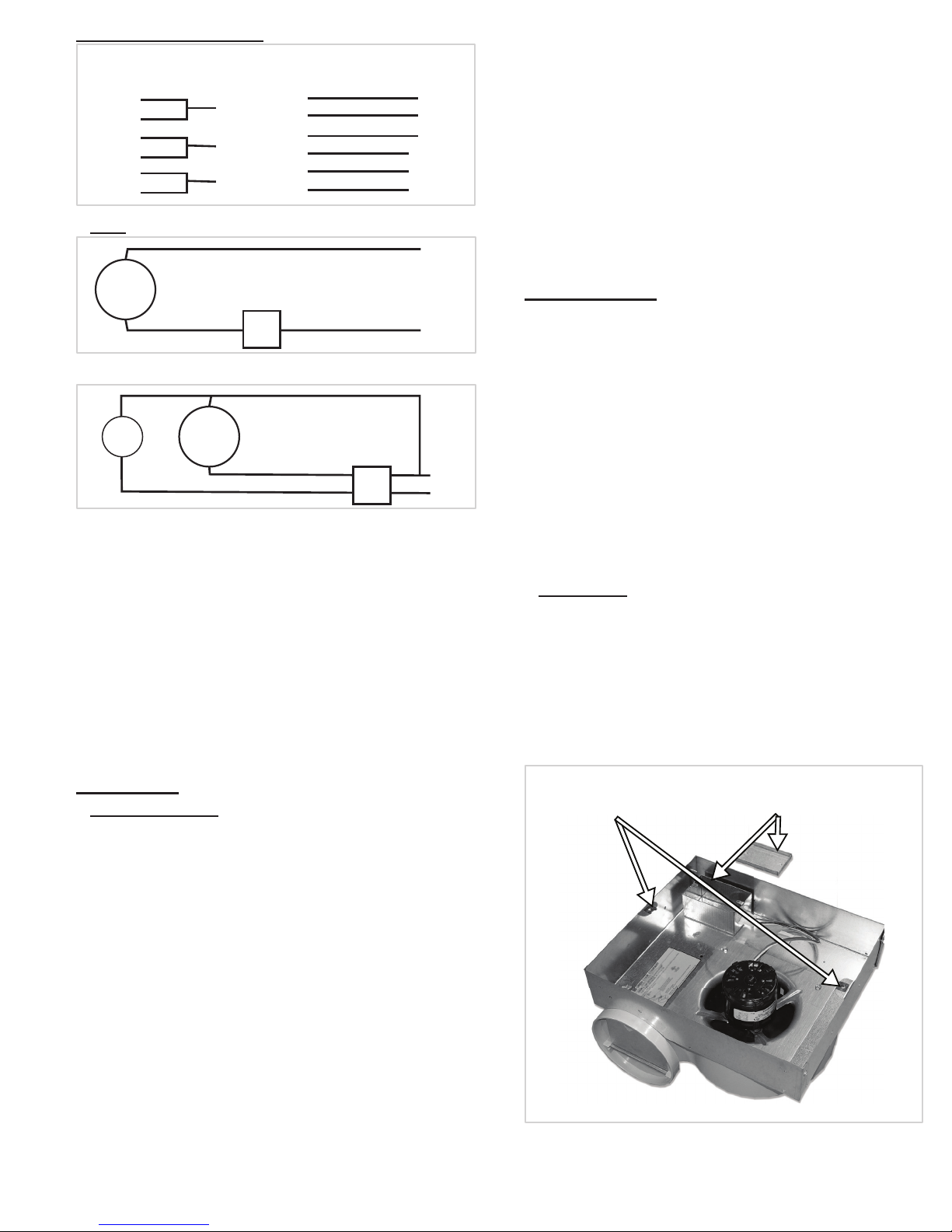
Gemini 200 - 700 series
Blower Mounting Brace
To inspect, clean, or repair, refer to the follow diagram
and follow these steps:
1. Remove grille.
2. Remove blower assembly from housing:
a. Disconnect the motor from electrical supply.
b. Remove mounting bolts.
c. Slide discharge ange out of spring clip and
move motor/blower assembly from box.
3. Remove inlet ring from blower housing.
4. Remove blower wheel with an allen wrench.
Wheel
Mounting Bolts
Unit
Mounting
Bracket
Adjustment
Wiring
Box
Bolts
Duct Collar
Motor
Damper
Blade
Gemini 800 - 2000 series:
To inspect, clean, or repair, refer to the diagram below
and follow these steps:
1. Remove grille.
2. Remove blower assembly from housing:
a. Disconnect the motor from the electrical supply.
b. Remove motor plate bolts.
c. Slide motor plate and remove motor/blower
assembly from box.
3. Remove inlet rings from blower housing (both sides).
4. Mark the wheel and housing to ensure correct
replacement of blower wheels (one is clockwise and
the other is counter-clockwise), then remove the
blower wheels with an allen wrench.
Wheel
Blower Housing
Motor Plate
Motor Plate Bolts
Reassembly
Simply reverse the disassembly instructions. Make sure
the wheel rotates in the same direction as the arrow on the
blower housing. Make sure the wheels do not rub on the
inlet rings. When replacing the motor, make sure the motor
and wheels are properly aligned with the blower housing.
Notice! Ensure that the blower discharge ange is
secured in slot of the cabinet on Gemini 200 - 700
series.
Motor Bearings
Motor bearings are pre-lubricated and sealed. Under
normal conditions they will not require further maintenance
for a period of ten years.
Motor Services
Should the motor prove defective within a one-year
period, contact your local Loren Cook representative or your
nearest authorized electric motor service representative
Troubleshooting
Problem and Potential Cause
Low Capacity or Pressure:
• Incorrect direction of rotation. Make sure the fan rotates
in same direction as the arrows on the motor or belt
drive assembly.
• Poor fan inlet conditions. There should be a straight
clear duct at the inlet.
• Improper wheel alignment.
• Damper held shut by tape.
• Screw attaching duct work to collar interfering with
damper operation.
Excessive Vibration and Noise:
• Damaged or unbalanced wheel.
• Belts too loose; worn or oily belts.
• Speed too high.
• Incorrect direction of rotation. Make sure the fan rotates
in same direction as the arrows on the motor or belt
drive assembly.
• Bearings need lubrication or replacement.
• Fan surge.
Overheated Motor:
• Motor improperly wired.
• Incorrect direction of rotation. Make sure the fan rotates
in same direction as the arrows on the motor or belt
drive assembly.
• Cooling air diverted or blocked.
• Improper inlet clearance.
• Incorrect fan RPMs.
• Incorrect voltage.
Motor
Inlet Ring
(Ensure proper clearance between wheel and inlet ring)
6GEMINI IO&M B51111-002
Page 7
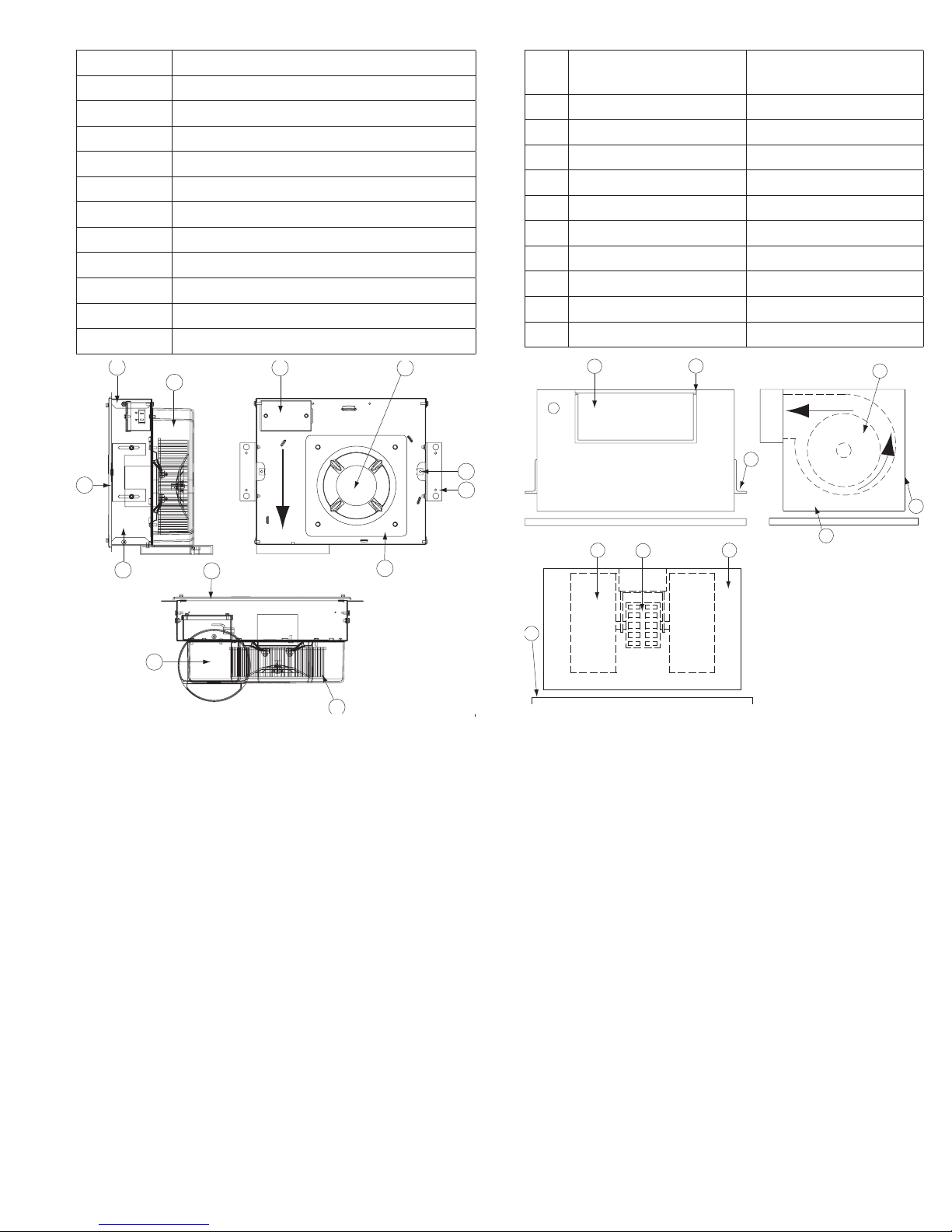
Gemini 100 Parts List
1
3
4
8
Part No. Part Description
1 Inlet Box End Plate (Ceiling only)
2 Housing/Scroll
3 Field Wiring Compartment
4 Motor
5 Tinnerman Clip (Grill) X2
6 Mounting Bracket
7 Backdraft Damper
8 Wheel
9 Motor Mount/Inlet
10 Inlet Box
11 Grille
2
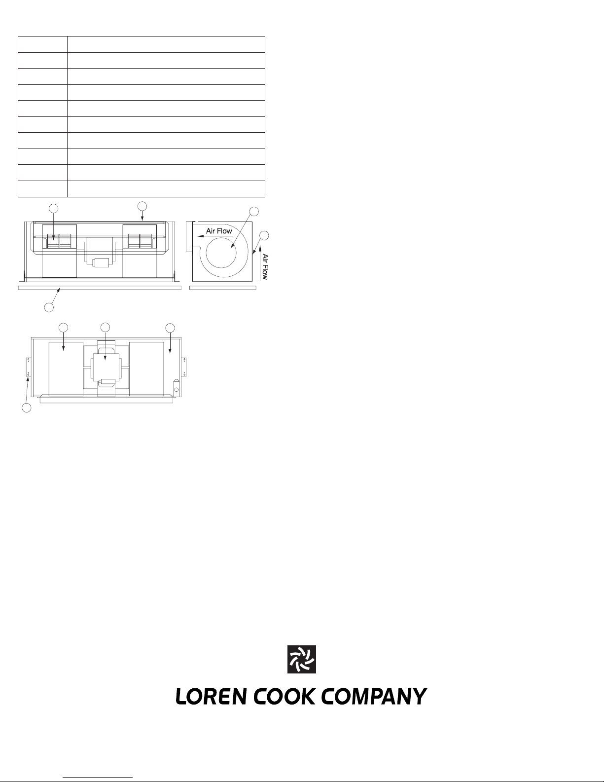
Gemini 200–900 Parts List
Part
No.
1 Backdraft Damper Backdraft Dampers (2)
2 Damper Frame Damper Frame (2)
3 Mounting Bracket (2) Mounting Bracket (2)
4 Wheel Wheel (2)
5 Grille (Ceiling and Wall) Grille (Ceiling and Wall)
6 Blower Housing Blower Housing (2)
7 Motor Motor
8 Insulation Insulation
9 Cabinet housing Cabinet housing
10 Housing Side Cover Housing Side Cover
Size 200–700 Size 800–900
1
2
Air Flow
4
11
10
7
11
Air Flow
9
5
6
67
5
3
10
9
8
7GEMINI IO&M B51111-002
Page 8
Gemini 1000–2000 Parts List
Part No. Part Description
1 Grille (ceiling and wall)
2 Backdraft Damper (2)
3 Wheel (2)
4 Blower Housing (2)
5 Motor
6 Insulation
7 Mount Brackets (2)
8 Cabinet housing
9 Housing Side Cover
2
1
8
3
9
4
7
5
6
Limited Warranty
Loren Cook Company warrants that your Loren Cook fan was manufactured free of defects in materials and workmanship, to the extent stated herein.
For a period of one (1) year after date of shipment, we will replace any parts found to be defective without charge, except for shipping costs which will be
paid by you. This warranty is granted only to the original purchaser placing the fan in service. This warranty is void if the fan or any par t thereof has been
altered or modied from its original design or has been abused, misused, damaged or is in worn condition or if the fan has been used other than for the
uses described in the company manual. This warranty does not cover defects resulting from normal wear and tear. To make a warranty claim, notify Loren
Cook Company, General Ofces, 2015 East Dale Street, Springeld, Missouri 65803- 4637, explaining in writing, in detail, your complaint and referring
to the specic model and serial numbers of your fan. Upon receipt by Loren Cook Company of your written complaint, you will be notied, within thirty
(30) days of our receipt of your complaint, in writing, as to the manner in which your claim will be handled. If you are entitled to warranty relief, a warranty
adjustment will be completed within sixty (60) business days of the receipt of your written complaint by Loren Cook Company. This warranty gives only
the original purchaser placing the fan in service specically the right. You may have other legal rights which vary from state to state.
Corporate Ofces: 2015 E. Dale St. Springeld, MO 65803
Phone 417-869-6474 | Fax 417-862-3820 | lorencook.com
March 2017
8GEMINI IO&M B51111-002
 Loading...