

Page 1
FCE / FCRU
Fiberglass Roof Exhausters
INSTALLATION, OPERATION AND MAINTENANCE MANUAL
This publication contains the installation, operation and
maintenance instructions for standard units of the FCE /
FCRU Fiberglass Roof Exhausters.
• FCED / FCEB
• FCRUD / FCRUB
Carefully read this publication and any
supplemental documents prior to any
installation or maintenance procedure.
Loren Cook Fiberglass catalog provides additional
information describing the equipment, fan performance,
available accessories, and specification data.
For additional safety information, refer to AMCA
publication 410-96, Safety Practices for Users and Installers
of Industrial and Commercial Fans.
The publication(s) listed above can be obtained from
Loren Cook Company by phoning (417)869-6474,
extension 166; by FAX at (417)832-9431; or by e-mail at
info@lorencook.com.
For information and instructions on special equipment,
contact Loren Cook Company at 417.869-6474.
Rotating Parts & Electrical Shock Hazard:
Disconnect electric power before working on unit.
Follow proper lockout / tagout procedures to ensure
the unit cannot be energized while being installed or
serviced.
A disconnect switch should be placed near the fan in
order that the power can be swiftly cut off, in case of
an emergency and in order that maintenance
personnel are provided complete control of the power
source.
Grounding is required. All field-installed wiring must
be completed by qualified personnel. All fieldinstalled wiring must comply with National Electric
Code (NFPA 70) and all applicable local codes.
Failure to follow these instructions could result in
death or serious injury.
Handling
Lift the fan by the shipping carton. NOTICE! Never lift by
the shaft, motor or housing.
Storage
If the fan is stored for any length of time prior to
installation, completely fill the bearings with grease or
moisture-inhibiting oil (refer to Lubricants on page 6).
Rotate the wheel several revolutions every three to five
days to keep a coating of grease on all internal bearing
parts.
Store the fan in its original crate and protect it from dust,
debris and the weather.
To maintain good working condition of the fan when it is
stored outdoors, follow the additional instructions below.
• Coat the shaft with grease or a rust preventative
compound.
• Wrap bearings for weather protection. Cover the inlet
and outlet to prevent the accumulation of dirt and
moisture in the housing.
• Periodically rotate the wheel and operate dampers (if
supplied). Periodically inspect the unit to prevent
damaging conditions.
Installation
If the fan was delivered with the motor unmounted, see
the maintenance section for belt and pulley installation.
Receiving and Inspection
Immediately upon receipt of the fan, carefully inspect the
fan and accessories for damage and shortage.
• Turn the wheel by hand to ensure it turns freely and
does not bind.
• Check dampers (if included) for free operation of all
moving parts.
• Record on the Delivery Receipt any visible sign of
damage.
FCE
FCRU
Page 2
The attachment of roof mounted fans to the roof curb
as well as the attachment of roof curbs to the building
structure must exceed the structural requirements
based on the environmental loading derived from the
applicable building code for the site. The local code
official may require variations from the recognized
code based on local data. The licensed engineer of
record will be responsible for prescribing the correct
attachment based on construction materials, code
requirements and environmental effects specific to
the installation.
Failure to follow these instructions could result in
death or serious injury.
motors have to be removed in order to make the connection
with the terminal box at the end of the motor.
NOTICE! Follow the wiring diagram in the disconnect
switch and the wiring diagram provided with the motor.
Correctly label the circuit on the main power box and
always identify a closed switch to promote safety (i.e.,
red tape over a closed switch).
1. Remove the top cap which covers the motor assembly
by unbolting the lid.
2. For internal wiring, run the electrical wire and conduit
through the opening drilled in the damper shelf (refer to
Damper Installation), then through the wiring conduit in
the ventilator base to the motor compartment. For
external wiring, run the wires through the horizontal
conduit on upblast units, or under top cap in downblast
units.
Pull the wires through and complete the wiring. For further
3.
information. Refer to Wiring Diagrams on page 3.
Damper Installation
If your fan is supplied with dampers, follow the directions
below. If your fan does not include dampers, proceed to
Belt and Pulley Installation.
1. Place the damper inside the curb or inside the duct
work. Ensure the damper will open freely for the correct
direction of the airflow.
2. Secure to curb at the damper shelf.
3. Drill hole in the curb shelf for conduit needed for motor
wiring.
4. Operate the dampers manually to ensure the blades
move freely.
5. Install fan over curb while aligning the conduit location
with the conduit hole in the curb.
Wiring Installation
NOTICE! All wiring should be in accordance
with local ordinances and the National Electrical
Code, NFPA 70. Ensure the power supply
(voltage, frequency, and current carrying
capacity of wires) is in accordance with the
motor nameplate. (See page 3 for diagram)
NOTICE! Fan must be grounded to prevent electrical
discharge.
For Units Without A Junction Box:
An approved metal field wiring compartment must be
secured to the unit with two screws in order that the box
does not rotate. All wires must be protected from abrasion
where they enter and exit the wiring compartment. The
green ground wire from the motor must be secured under
the green ground screws inside the field wiring compartment
using a closed loop connector. Complete connections in
accordance with the wiring diagram on the motor.
For Units With A Junction Box:
Pull wires through the appropriate conduit. Protect wires
from abrasion where they enter the field wiring compartment
and complete connections in accordance with the diagram
on the motor.
Leave enough slack in the wiring to allow for motor
movement when adjusting belt tension. Some fractional
Final Installation Steps
1. Ensure fasteners and set screws, particularly fan
mounting and bearing fasteners are tightened
according to the recommended torque shown on the
table below.
2. Inspect for correct amperage with an ammeter and
correct voltage with a voltmeter.
3. Ensure that all accessories are installed.
4. Test the fan to be sure the rotation is the same as
indicated by the arrow marked ‘Rotation’.
NOTICE! Do not allow the fan to run in the wrong
direction. This will overheat the motor and cause
serious damage. For 3-phase motors, if the fan is
running in the wrong direction, check the control
switch. It is possible to interchange two leads at
this location so that the fan is operating in the
correct direction.
5. Inspect wheel-to-inlet clearance. Wheels may shift in
shipment. To realign wheel-to-inlet, shift upper bearing
so there is an equal radial clearance between the wheel
and inlet. Refer to wheel to inlet clearance on page 6.
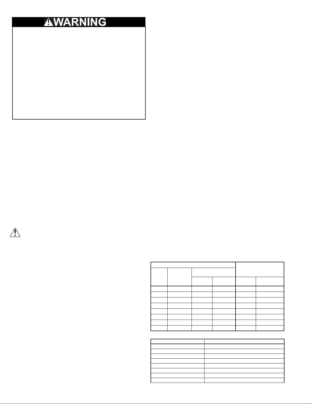
Recommended Torque for Setscrews/Bolts on metal(IN-LB)
Setscrews
Size
No.10 3/32” 28 33 3/8”-16 240
1/4” 1/8” 66 80 1/2”-13 600
5/16” 5/32” 126 156 5/8”-11 1200
3/8” 3/16” 228 275 3/4”-10 2100
7/16” 7/32” 29 348 7/8”-9 2040
1/2” 1/4” 42 504
5/8” 5/16” 92 1104
3/4” 3/8” 120 1440
Key Hex
Across
Flats
Recommended
Torque
Min. Max. Size
Recommended Torque for Setscrews/Bolts on FRP (FT-LB)
Size (inches) 18-8 SST Hardware Torque
No 10 7
1/4” 12
5/16” 20
3/8” 30
7/16” 41
1/2” 54
5/8” 86
3/4” 128
Hold Down Bolts
Wrench
Torque
2
Page 3

Wiring Diagrams
Single Speed, Single Phase Motor
Ground A
L
T-1
T-4
Ground B
When ground is required, attach to ground A or B with no. 6 thread forming
screw. To reverse, interchange T-1 and T-4.
1
Line
L
2
Wiring Diagrams
3 Phase, 9 Lead Motor
Y-Connection
Low Voltage
208/230 Volts
4
5
6
3
1
9
728
L2L
L
1
To reverse, interchange any 2 line leads.
3
High Voltage
460 Volts
456
789
3
12
L2L
L
3
1
3 Phase, 9 Lead Motor
Delta-Connection
Low Voltage
208/230 Volts
7
6
1
L
L
1
2 Speed, 2 Winding, Single Phase Motor 2 Speed, 1 Winding, 3 Phase Motor
Ground A
T-1
T-4
Ground B
High Speed
Low Speed
L
1
Line
L
2
When ground required, attach to ground A or B with No. 6 thread forming
screw. To reverse, interchange T-1 and T-4 leads.
Motor
To reverse, interchange any 2 line leads. Motors require magnetic control.
High Speed
1
Together
2
3
L
4
1
L
5
6
L
Motor
2
Line
3
Single Speed, Single Phase, Dual Voltage 2 Speed, 2 Winding, 3 Phase
Ground A
L
T-5
J-10
Link A
Link B
Low Voltage
Ground B
Line
L
1
T-5
J-10
2
Ground B
When ground required, attach to ground A or B with No. 6 thread forming
screw. To reverse, interchange T-5 and J-10 leads.
Ground A
Link A & B
L
Line
L
1
2
To reverse: High Speed-interchange leads T11 and T12.
Low Speed-interchange leads T1 and T2. Both Speeds-interchange any 2
line leads.
Typical Damper Motor Schematic
9
8
5
4
3
2
L
3
2
Low Speed
1
2
3
4
5
6
High Voltage
460 Volts
789
456
3
12
L1L
L
3
2
L
1
L
2
Line
L
3
Open
Fan
Motor
L3
L2
L1
For 3 phase, damper motor voltage should be the same between L1 and
L2. For single phase application, disregard L3. *Damper motors may be
available in 115, 230 and 460 volt models. The damper motor nameplate
voltage should be verified prior to connection. ** A transformer may be
Transformer**
Damper
Motor*
Second
Damper
Motor
Transformer**
provided in some installations to correct the damper motor voltage to the
specified voltage.
Operation
Pre-Start Checks
1. Lock out all the primary and secondary power sources.
2. Inspect and tighten fasteners and setscrews, particularly
fan mounting and bearing fasteners Refer to Torque chart.
3. Inspect belt tension and pulley alignment. Refer to Belt
and Pulley Installation, page 4.
4. Inspect motor wiring. Refer to Wiring Installation.
5. Ensure belt touches only the pulleys.
6. Rotate the wheel to ensure it rotates freely.
7. Ensure fan and ductwork are clean and free of debris.
8. Close and secure all access doors.
9. Restore power to fan.
Start-up
Turn on the fan. In variable speed units, set the fan to its
lowest speed. Inspect for the following:
• Direction of rotation
• Excessive vibration
• Excessive vibration
• Unusual noise
• Bearing noise
• Improper belt alignment or tension (listen for squealing)
• Improper motor amperage or voltage
If a problem is discovered, immediately shut the fan
off. Lock out all electrical power and check for the cause
of the trouble. Refer to Troubleshooting on page 6.
3
Page 4

Inspection
Inspection of the fan should be conducted at the first 30
minute, 8 hour and 24 hour intervals of satisfactory
operation. During the inspections, stop the fan and inspect
as instructed.
30 Minute Interval:
Inspect bolts, setscrews, and motor mounting bolts. Adjust
and tighten as necessary.
8 Hour Interval:
Inspect belt alignment and tension. Adjust and tighten as
necessary.
24 Hour Interval:
Inspect belt tension. Adjust and tighten as necessary.
Maintenance
Establish a schedule for inspecting all parts of the fan. The
frequency of inspection depends on the operating conditions
and location of the fan.
Inspect fans exhausting corrosive or contaminated air
within the first month of operation. Fans exhausting
contaminated air should be inspected every three months.
It is recommended the following inspections be conducted
twice per year.
• Inspect bolts and setscrews for tightness. Tighten as
necessary. Refer to Torque chart.
• Inspect belt wear and alignment. Replace worn belts with
new belts and adjust alignment as needed. Refer to Belt
and Pulley Installation, page 4.
• Bearings should be inspected as recommended in the
Conditions Chart.
• Inspect for cleanliness. Clean exterior surfaces only.
Removing dust and grease on motor housing assures
proper motor cooling.
Fan Bearings
NOTICE! The fan bearings are provided
prelubricated. Any specialized lubrication instructions
on fan labels supersedes information provided herein.
Bearing grease is a petroleum lubricant in a lithium
base conforming to a NLGI #2 consistency. If user
desires to utilize another type of lubricant, they take
responsibility for flushing bearings and lines, and
maintaining a lubricant that is compatible with the
installation.
A NLGI #2 grease is a light viscosity, low-torque, rustinhibiting lubricant that is water resistant. Its temperature
range is from -30°F to 200°F and capable of intermittent
highs of 250°F.
Bearings should be relubricated in accordance with the
condition chart below.
Conditions Chart
RPM Temp °F Greasing Interval
Up to 1000
1000 to 3000
Over 3000
Any Speed < -30 Consult Factory
For moist or otherwise contaminated installations; divide the interval by a
factor of 3. For vertical shaft installations divide the interval by a factor of 2.
For best results, lubricate the bearing while the fan is in
-30 to 120 6 months
120 to 200 2 months
-30 to 120 3 months
120 to 200 1 month
-30 to 120 1 month
120 to 200 2 weeks
operation. Pump grease in slowly until a slight bead forms
around the bearing seals. Excessive grease can damage
seal and reduce life through excess contamination and/or
loss of lubricant.
In the event that the bearing cannot be seen, use no more
than three injections with a hand operated grease gun.
Motor Bearings
Motor bearings without provisions for relubrication will
operate up to 10 years under normal conditions with no
maintenance. In severe applications, high temperatures or
excessive contaminates, it is advisable to have the
maintenance department disassemble and lubricate the
bearings after 3 years of operation to prevent interruption of
service.
For motors with provisions for relubrication, follow
intervals of the table below.
Relubrication Intervals
Service
Conditions
Standard 3 yrs. 6 months 2 yrs. 6 months 1 yr. 3 months
Severe 1 yr. 3 months 1 yr. 3 months 6 months 1 months
Up to and
including 184T
1800 RPM
and less
Over 1800
RPM
NEMA Frame Size
213T-365T 404T and larger
1800 RPM
and less
Over 1800
RPM
1800 RPM
and less
Over 1800
RPM
NOTICE! Motors are provided with a polyurea mineral
oil NGLI #2 grease. All additions to the motor bearings
are to be with a compatible grease such as Exxon Mobil
Polyrex EM and Chevron SRI.
The above intervals should be reduced to half for vertical
shaft installations.
Motor Services
Should the motor prove defective within a one-year period,
contact your local Loren Cook representative or your nearest
authorized electric motor service representative.
Changing Shaft Speed
All belt driven ventilators (5HP or less) are equipped with
variable pitch pulleys. To change fan speed, perform the
following:
1. Loosen setscrew on driver (motor) pulley and remove
key, if equipped.
2. Turn the pulley rim to open or close the groove facing. If
the pulley has multiple grooves, all must be adjusted to
the same width.
3. After adjustment, inspect for proper belt tension.
Maximum RPM (Refer to the catalog for max performance.)
Size
120 4500 4500
150 3600 4300
180 2900 3600
245 2200 2700
270 2000 2400
300 1800 2200
330 1650 2000
365 1500 1800
402 1350 1650
Standard HP only
Speed Reduction:
Open the pulley in order that the belt rides deeper in the
groove (smaller pitch diameter).
Speed Increase:
Close the pulley in order that the belt rides higher in the
groove (larger pitch diameter). Ensure that the RPM limits of
the fan and the horsepower limits of the motor are
maintained.
4
Maximum RPM
Page 5

Replacing Pulleys and Belts
1 foot
1/4 inch
1. Clean the motor and fan shafts.
2. Loosen the motor plate mounting bolts to relieve the belt
tension. Remove the belt.
3. Loosen the pulley setscrews and remove the pulleys
from the shaft. If excessive force is required to remove
the pulleys, a three-jaw puller can be used. This tool,
however, can easily warp a pulley. If the puller is used,
inspect the trueness of the pulley after it is removed
from the shaft. The pulley will need replacement if it is
more than 0.020 inch out of true.
4. Clean the bores of the pulleys and place a light coat of
oil on the bores.
5. Remove any grease, rust or burrs from pulleys.
6. Place the fan pulley on the fan shaft and the motor
pulley on the motor shaft. Damage to the pulleys can
occur when excessive force is used in placing the
pulleys on their respective shafts.
7. After the pulleys have been correctly placed back onto
their shafts, tighten the pulley setscrews.
Belt and Pulley Installation:
Belt tension is determined by the sound of the belts when
the fan is first started. The belts will produce a loud squeal,
which dissipates after the fan is operating at full capacity. If
belt tension is too tight or too loose, lost efficiency and
damage may occur.
Do not change the pulley pitch diameter to change tension.
The change will result in a different fan speed.
Figure 1
1. Loosen motor plate adjustment bolts and slide motor
plate so that belts easily slip into the grooves on the
pulleys. Never pry, roll, or force the belts over the rim of
the pulley.
2. Slide motor plate until proper tension is reached. For
proper tension, a deflection of approximately 1/4” per
foot of center
distance should
be obtained by
firmly pressing
the belt. Refer to
Figure 1.
3. Lock the motor
plate adjustment
bolts in place.
4. Ensure pulleys
are properly
aligned. Refer to
Figure 2.
Figure 2
OFFSET ANGULAR OFFSET/ANGULAR
A
W
X
Y
Z
B
CENTER
DISTANCE
(CD)
Tolerance
Center Distance
Up thru 12” 1/16”
12 through 48” 1/8”
Over 48” 1/4”
GAP
Maximum
Gap
GAP
Pulley Alignment
Pulley alignment is adjusted by
loosening the motor pulley
setscrew and by moving the motor
pulley on the motor shaft.
Figure 2 indicates where to
measure the allowable gap for the
drive alignment tolerance. All
contact points (indicated by WXYZ)
are to have a gap less than the
tolerance shown in the table. When
the pulleys are not the same width,
the allowable gap must be adjusted
Figure 3
by half of the difference in width. Figure 3 illustrates using a
carpenter’s square to adjust the position of the motor pulley
until the belt is parallel to the longer leg of the square.
Bearing Replacement
The fan bearings are pillow block type ball bearings.
1. Follow all local lock-out / tag-out procedures, remove
topcap from unit and unwire the units motor.
2. Loosen the bolts holding the motor and remove the belt.
Inspect the belt for signs of wear and set aside.
3. While supporting the motor, either by the lifting eye or
around the base on the motor, loosen and remove all
the bolts holding the motor. Do not lift motor by its shaft.
Caution: Motors with cast frames can be extremely
heavy and should not be lifted without additional aid.
Set motor aside.
4. Locate the 4 to 8 bolts on the flat surface of the interior
of the housing. Begin to loosen these bolts and save
the hardware. Note unit may shift during this process.
5. Using the lifting points on the power assembly carefully
lift the assembly straight up until the wheel clears all
parts of the unit. Set the wheel / shaft / power assembly
down in a manner that does not damage the roof or any
component.
6. Measure and record the distance of the wheel from the
support plate.
7. Using a putty knife at the wheel hub, scrape the resin
from the safety plate and retaining bolt.
8. Remove the retaining bolt and safety plate and set
aside.
9. Using either a jewelry screw driver or small drill bit,
remove the beeswax from the set screw openings and
set screw heads.
10. Remove the wheel and remove the old bearings and
shaft.
11. Install the new shaft to the wheel, safety plate, and
retaining bolt. Tighten all per the torque values as
stated on page 2.
12. Using a fiberglass resin repair kit, apply resin per the
manufacture instruction over the safety plate, and
retaining bolt. Recommend using a Grainger part
number 3RAR9 or equal.
13. Reapply beeswax to protect the set screw heads.
14. Install the new shaft by sliding the bearings to the
desired location using the measurement record earlier
and loosely mounting the bearing support. Bearing bolts
and bearing set screws should be loose enough to allow
5
Page 6

shaft position later.
15. Follow step 2 thru 6 in reserve order to re-assembly
unit. Please note the wheel to inlet clear matches as
close as possible the diagram on page below
16. Tighten all hardware per the torque values as stated on
page 2 and follow the Operation Pre-Start Check and
Start-Up listed in this document.
Wheel-to-Inlet Clearance
The correct wheel-to-inlet clearance is critical to proper
fan performance. This clearance should be verified before
initial start-up since rough handling during shipment could
cause a shift in fan components. Refer to wheel/inlet
drawing for correct overlap.
Adjust the overlap by loosening the wheel hub and
moving the wheel along the shaft to obtain the correct value.
A uniform radial gap (space between the edge of the cone
and the edge of the inlet) is obtained by loosening the
bearing bolts and set screws which will allow for correct
repositioning.
Wheel / Inlet Overlap
Size
60 - 195 5/8”
210 - 270 3/4”
300 - 445 1”
490-730 1-1/4”
100 5/8”
Radial Clearance
Overlap
Maximum
Overlap
This warranty gives only the original purchaser placing the
fan in service specifically the right. You may have other legal
rights which vary from state to state.
For fans provided with motors, the motor manufacturer
warrants motors for a designated period stated in the
manufacturer’s warranty. Warranty periods vary from
manufacturer to manufacturer. Should motors furnished by
Loren Cook Company prove defective during the designated
period, they should be returned to the nearest authorized
motor service station. Loren Cook Company will not be
responsible for any removal or installation costs.
Troubleshooting
Problem and Potential Cause
Low Capacity or Pressure
•Incorrect direction of rotation. Make sure the fan rotates in same direction
as the arrows on the motor or belt drive assembly.
•Poor fan inlet conditions. There should be a straight clear duct at the inlet.
•Improper wheel alignment.
Excessive Vibration and Noise
•Damaged or unbalanced wheel.
•Belts too loose; worn or oily belts.
•Speed too high.
•Incorrect direction of rotation. Make sure the fan rotates in same direction
as the arrows on the motor or belt drive assembly.
•Bearings need lubrication or replacement.
•Fan surge.
Overheated Motor
•Motor improperly wired.
•Incorrect direction of rotation. Make sure the fan rotates in same direction
as the arrows on the motor or belt drive assembly.
•Cooling air diverted or blocked.
•Improper inlet clearance.
•Incorrect fan RPMs.
•Incorrect voltage.
Spare parts
Spare parts are not needed for the first year of operation. If
spare parts are desired, then it is suggested that a spare
motor and impeller be ordered for direct drive fans. For belt
drive fans, in addition to the motor and impeller, it is
suggested that a spare set of bearings, shaft, sheaves, and
belts be ordered.
When ordering spare parts, specify the parts desired, the
fan model number, and the fan serial number. Contact your
local sales representative for price and delivery.
Limited Warranty
Loren Cook Company warrants that your Loren Cook fan
was manufactured free of defects in materials and
workmanship, to the extent stated herein. For a period of one
(1) year after date of shipment, we will replace any parts
found to be defective without charge, except for shipping
costs which will be paid by you.
This warranty is granted only to the original purchaser
placing the fan in service.
LOREN COOK COMPANY
Corporate Offices: 2015 E. Dale Street Springfield, MO 65803 417.869.6474
lorencook.com
Overheated Bearings
•Improper bearing lubrication
•Excessive belt tension.
6
FCE IOM - June 2013
 Loading...