

Page 1

WARNING
This unit has rotating parts. Safety precautions
should be exercised at all times during installation,
operation, and maintenance.
Unit must be grounded to electrical service panel.
ALWAYS disconnect power prior to working on fan.
Failure to comply with these safety precautions could
result in property damage, serious injury or death.
ERV
ENERGY RECOVERY VENTILAT OR
INSTALLATION, OPERATION, AND MAINTENANCE MANUAL
This publication contains the installation, operation
and maintenance instructions for st andard units of the
ERV-Energy Recovery Ventilators.
For ERV with coils refer to DX & Fluid Supplements.
For cooling coil units, refer to Page 8 of this manual
for guidelines on the installation of condensate drain
traps.
Carefully read this publication prior to any installation or maintenance procedure.
Loren Cook catalog, ERV, provides additional informa-
tion describing the equipment, fan performance, available
accessories, and specification data.
For additional safety information, refer to AMCA Publication 410-96, Safety Practices for Users and Installers of
Industrial and Commercial Fans.
All of the publications listed above can be obtained from
Loren Cook Company by phoning (417)869-6474, extension 166; by FAX at (417)832-9431; or by e-mail at
info@lorencook.com.
For information on special equipment, contact Loren
Cook Company Customer Service Department at
(417)869-6474.
Receiving and Inspection
Carefully inspect the ERV and ERV accessories for any
damage and any shortage of accessories immediately
upon receipt of the fan.
• Turn each blower wheel by hand to ensure it turns
freely and does not bind.
• Inspect dampers (if supplied) for free operation of all
moving parts.
• Record on the Delivery Receipt any visible sign of
damage.
Storage
If the ERV is stored for any length of time prior to installation, store the ERV in its original crate and protect it from
dust, debris and the weather.
ERV Installation
Before installing, turn the energy wheel by hand in the
direction of rotation to insure that the wheel alignment was
not altered in shipping.
The ERV seals were preadjusted before leaving the factory. If upon inspection excessive clearance between seals
and sealing surfaces is found, adjust the seals according to
the procedure.
Inspect the drive belt and make sure that it is around the
drive sheaves and wheel. If possible, test run the wheel
before installation.
ERV 1500 - 10,000 ERV 500 - 1,000
Page 2
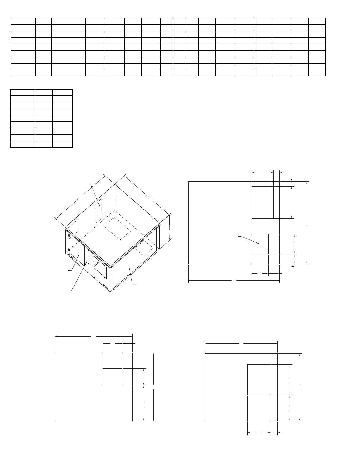
Return Air
Filter
Access Door
Right
Control Panel
Access Door,
Exhaust Blower
Access Door
Left
Front
Back
Removable Plug
for Field
Electrical
Connections
Supply Blower,
Rotary Wheel,
And Filter
Access Door
C
B
A
Arrangement V
A
Back View
B
E
K
D
L
Exhaust
Air
Discharge
Left View
Outdoor
Air
Intake
B
C
F
S
G
R
Top View
E
D
A
M
N
C
H
JQ
P
Return
Air
Intake
Supply
Air
Discharge
Dimensions - Arrangement V
Unit A A (Coil Units) B C D E F G H J K L M N P Q
ERV 1500 54-3/16 90-3/16 40-13/32 49-9/32 10-1/4 11-13/16 18 14 19 13 6-1/8 21-1/8 6-1/16 6-11/16 3-5/8 3-1/4
ERV 2500 52-1/8 88-1/8 50-1/8 52-1/8 11-3/8 13-1/8 28 20 21 11-3/4 5-1/16 29-5/16 7-5/16 7-1/16 3-1/2 3-3/8
ERV 3500 64-1/2 100-1/2 59 60-1/2 13-7/16 15-5/8 34 20 23 16-1/2 5-7/8 33-13/16 8-13/16 7-13/16 4-3/4 4-1/8
ERV 4500 69-1/2 105-1/2 64-1/2 66-1/2 13-7/16 15-5/8 34 24 26 18-3/4 7-5/16 38-5/8 10 8-1/8 4-3/4 4-1/8
ERV 5500 69-1/2 105-1/2 71 66-1/2 15-7/8 18-5/8 44 24 26 18-3/4 5-7/16 41 8-13/16 9-3/8 4-3/4 4-1/8
ERV 7000 79-1/2 115-1/2 76-1/2 80 18-7/8 21-7/8 44 29 32 24 6-3/16 14-3/16 8-15/16 11-1/8 4-3/4 4-1/8
ERV 8500 79-1/2 115-1/2 83 80 18-7/8 21-7/8 53 29 32 24 6-3/16 14-3/16 8-15/16 11-1/8 4-3/4 4-1/8
ERV 10000 100 136 90 84-1/2 24-3/4 24-3/4 50 37 34-1/2 33 9-1/8 15-1/4 8 12-3/4 4-3/4 4-1/8
All dimensions in inches.
Unit R S
ERV 1500 4-1/16 15-5/8
ERV 2500 2-7/8 18-1/4
ERV 3500 6-1/4 18-1/16
ERV 4500 5-1/4 23-7/8
ERV 5500 5-1/4 20-1/8
ERV 7000 6-15/16 25-15/16
ERV 8500 6-15/16 22-15/16
ERV 10000 3-1/4 31-15/16
All dimensions in inches.
2
Page 3
Return Air
Filter
Access Door
Right
Control Panel
Access Door,
Exhaust Blower
Access Door
Left
Front
Removable Plug
for Field
Electrical
Connections
Supply Blower,
Rotary Wheel,
And Filter
Access Door
C
B
A
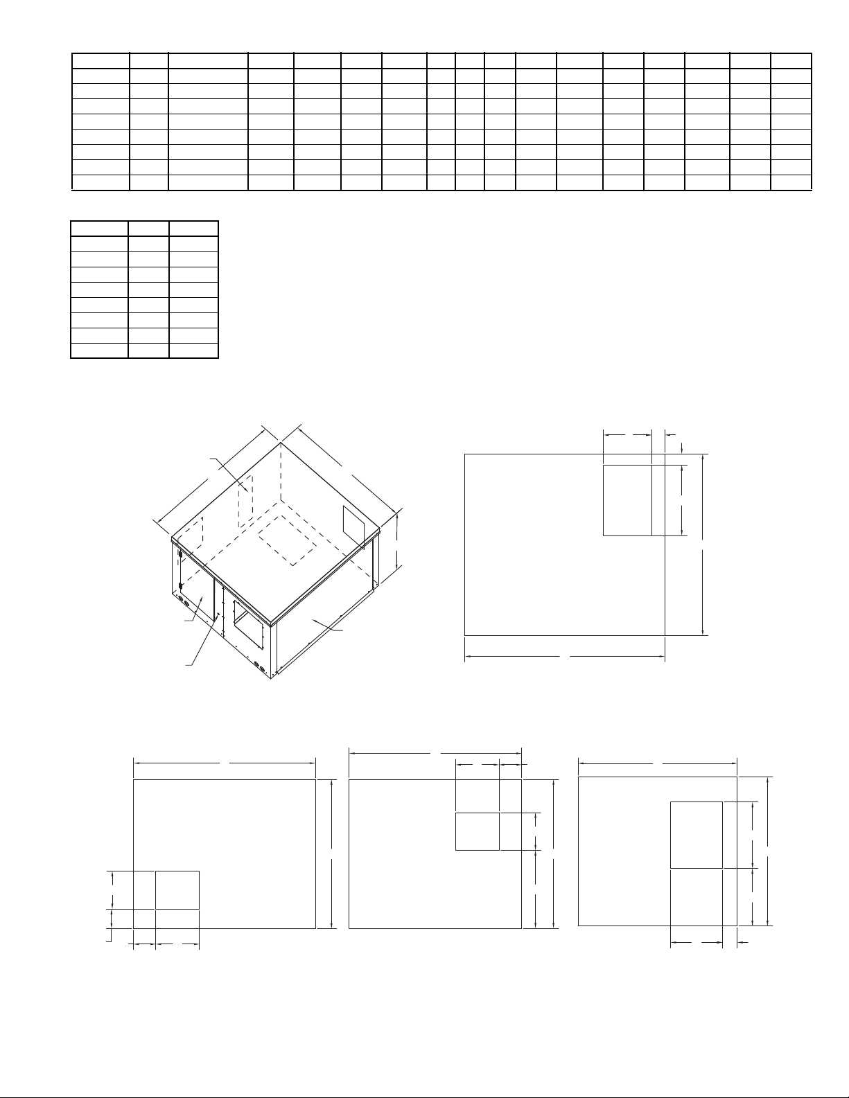
Arrangement C
H
Right View
B
E
K
D
L
Return
Air
Intake
Left View
Outdoor
Air
Intake
B
C
F
S
G
R
Back View
E
D
A
M
N
C
Q
P
Exhaust
Air
Discharge
Supply
Air
Discharge
C
J
Back
B
A
Top View
Dimensions - Arrangement C
Unit A A (Coil Units) B C D E F G H J K L M N P Q
ERV 1500 54-3/16 90-3/16 40-13/32 49-9/32 10-1/4 11-13/16 18 14 19 13 5-9/32 6 6-1/8 21-1/8 3-5/8 3-1/4
ERV 2500 52-1/8 88-1/8 50-1/8 52-1/8 11-3/8 13-1/8 28 20 21 11-3/4 9-7/8 7-3/8 5-1/16 29-5/16 3-1/2 3-3/8
ERV 3500 64-1/2 100-1/2 59 60-1/2 13-7/16 15-5/8 34 20 23 16-1/2 10-7/8 8-13/16 5-7/8 33-13/16 4-3/4 4-1/8
ERV 4500 69-1/2 105-1/2 64-1/2 66-1/2 13-7/16 15-5/8 34 24 26 18-3/4 10-13/16 7-3/16 7-5/16 38-9/16 4-3/4 4-1/8
ERV 5500 69-1/2 105-1/2 71 66-1/2 15-7/8 18-5/8 44 24 26 18-3/4 12-1/4 8-7/8 5-7/16 41 4-3/4 4-1/8
ERV 7000 79-1/2 115-1/2 76-1/2 80 18-7/8 21-7/8 44 29 32 24 14-1/4 9-1/16 6-3/16 14-3/16 4-3/4 4-1/8
ERV 8500 79-1/2 115-1/2 83 80 18-7/8 21-7/8 53 29 32 24 14-1/4 9-3/16 6-3/16 14-3/16 4-3/4 4-1/8
ERV 10000 100 136 90 84-1/2 24-3/4 24-3/4 50 37 34-1/2 33 15-7/16 8-1/4 9-1/8 15-1/4 4-3/4 4-1/8
All dimensions in inches.
Unit R S
ERV 1500 4-1/16 15-5/8
ERV 2500 2-7/8 18-1/4
ERV 3500 6-1/4 18-1/16
ERV 4500 5-1/4 23-7/8
ERV 5500 5-1/4 20-1/8
ERV 7000 6-15/16 25-15/16
ERV 8500 6-15/16 22-15/16
ERV 10000 3-1/4 31-15/16
All dimensions in inches.
3
Page 4
Return Air
Filter
Access Door
Right
Control Panel
Access Door,
Exhaust Blower
Access Door
Left
Front
Back
Removable Plug
for Field
Electrical
Connections
Supply Blower,
Rotary Wheel,
And Filter
Access Door
C
B
A
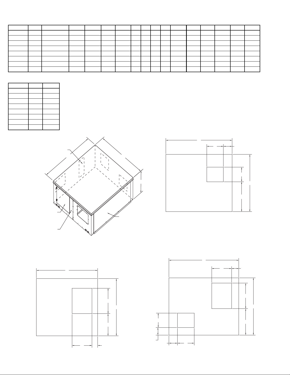
Arrangement H
H
Right View
B
E
K
D
L
Return
Air
Intake
Left View
Outdoor
Air
Intake
B
C
F
S
G
R
Back View
E
D
A
M
N
B
Q
P
Exhaust
Air
Discharge
Supply
Air
Discharge
C
J
Dimensions - Arrangement H
Unit A A (Coil Units) B C D E F G H J K L M N P Q
ERV 1500 54-3/16 90-3/16 40-13/32 49-9/32 10-1/4 11-13/16 18 14 14 18 5-9/32 6 5-1/8 18-5/8 6-1/8 21-1/8
ERV 2500 52-1/8 88-1/8 50-1/8 52-1/8 11-3/8 13-1/8 28 20 20 28 9-7/8 7-3/8 5-9/16 13-1/4 5-1/16 29-5/16
ERV 3500 64-1/2 100-1/2 59 60-1/2 13-7/16 15-5/8 34 20 20 34 10-7/8 8-13/16 5-5/16 18 5-7/8 33-13/16
ERV 4500 69-1/2 105-1/2 64-1/2 66-1/2 13-7/16 15-5/8 34 24 24 34 10-13/16 7-3/16 4-5/16 23-13/16 7-5/16 38-5/8
ERV 5500 69-1/2 105-1/2 71 66-1/2 15-7/8 18-5/8 44 24 23 42 12-1/4 8-7/8 4-5/16 22 5-7/16 41
ERV 7000 79-1/2 115-1/2 76-1/2 80 18-7/8 21-7/8 44 29 27 42 14-1/4 9-1/16 7-1/8 27-7/8 6-3/16 14-3/16
ERV 8500 79-1/2 115-1/2 83 80 18-7/8 21-7/8 53 29 27 46 14-1/4 9-3/16 7-1/8 29-7/8 6-3/16 14-3/16
ERV 10000 100 136 90 84-1/2 24-3/4 24-3/4 50 37 32 48 15-7/16 8-1/4 4-3/8 33-7/8 9-1/8 15-1/4
All dimensions in inches.
Unit R S
ERV 1500 4-1/16 15-5/8
ERV 2500 2-7/8 18-1/4
ERV 3500 6-1/4 18-1/16
ERV 4500 5-1/4 23-7/8
ERV 5500 5-1/4 20-1/8
ERV 7000 6-15/16 25-15/16
ERV 8500 6-15/16 22-15/16
ERV 10000 3-1/4 31-15/16
All dimensions in inches.
4
Page 5
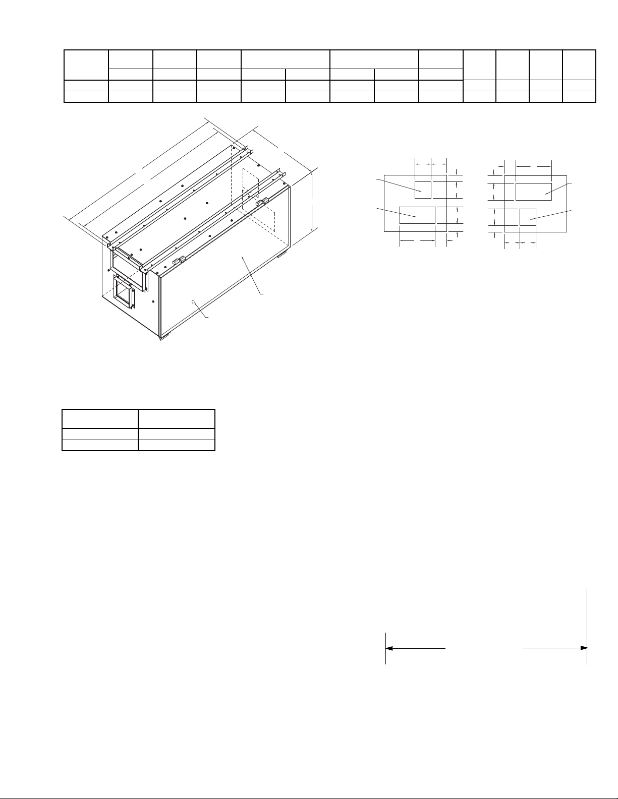
Removable Plug
For Field
Electrical
Connections
(Bottom Panel)
Hinged Access to
All Internal Components
Front
Left View
K E
J
D
F
Supply Air
Discharge
Return Air
Intake
G
M
L
Right View
F
G
M
L
K
E
J
D
B
Outdoor Air
Intake
C
Exhaust Air
Discharge
A
Right
H
Back
Left
Dimensions - Direct Drive
Unit
Mounting
Rail Length
Housing
Width
Housing
Height
Exhaust Opening Intake Opening
Mounting
Holes
JKLM
ABCDEFGH
ERV 500 52 22 23-13/16 7 5-11/16 7 12 50 4 5-5/16 1-1/2 4
ERV 1000 52 26 28-13/16 10-3/8 6-7/8 7 20 50 6-11/16 11-7/16 1-1/2 4
All dimensions in inches.
Service Clearance- Direct Drive
Unit
500 30
1000 35
All dimensions in inches.
Service
Clearance
Service Clearance
5
Page 6

Service Clearance - Belt Drive
Unit Size Filter Clearance Blower Clearance Cassette Clearance
1500 30 29 61
2500 31 31 64
3500 31 35 73
4500 26 41 79
5500 26 47 79
7000 30 52 92
8500 30 60 92
10000 30 60 96
All dimensions in inches.
Filter
Clearance
Blower
Clearance
Handling
Lift the ERV by the
base lifting holes.
Never lift by the
Cleavis
Pins
weatherhood. T o avoid
structural damage,
only lift the unit with all
service panels
Lifting Holes
installed.
After installing cleavis pins through all lifting holes, lift unit
a few feet off the ground and check to make sure the unit is
not tilted or twisted.
Cassette
Access
Clearance
Spreader Bars
To protect unit from damage when lifting, the lifting straps
and spreader bars should be utilized as shown in figure
below. To prevent scratching of the exterior surface, pads
should be placed between the cabinet and the cables.
Spreader Bar
6
Page 7

B
A
D
C
F
E
Energy Recovery Ventilator Definitions
Bearing, external - Flanged or pillow block bearing used with rotating shaft models.
Bearing, internal - Sealed ball bearing used with fixed shaft models.
Bulb seal - The seal used for both the cir cumferential seal and the inner seal in the cassettes. They are co nstructed of
neoprene and configured to seal against the wheel band in the ca se of the circumferentia l seal, and against th e wheel
face in the case of the inner seal. These seals are noncontact in that there is a slight gap between seal and sealing
face to allow the wheel to turn at high RPMs without overtorquing motor or causing seal damage. These seals have an
integral clip and are clipped to the cassette face panel cutout (circumferential) or to the post (inner).
Cassette - The steel structure that houses the wheel. Typically ERV cassettes are of punched sheet metal panelized
construction.
Energy Enthalpy Wheel - A generic name for an energy conservation wheel. The term enthalpy refers to an air
stream’s total energy (temperature and humidity level).
Exhaust Air - The air stream leaving an ERV that is exhausted to the outside. Exhaust air is building return air that has
been run through the wheel.
Heat Wheel - Synonymous with enthalpy wheel, energy conservation wheel, or total energy recovery wheel. Some
heat wheels are sensible only wheels and should not be confused with total energy recovery wheels.
Latent Energy - Latent energy in the context of wheel discussions is the work done by the wheel to transfer moisture
from one air stream to another. Latent work is accompanied by humidity changes in the air streams.
Media - The chemical composite part of the wheel which actually performs the latent and sensible exchange.
Outdoor Air - The air stream entering an ERV that is brought in from outside. Outdoor air becomes supply air after
going through the wheel.
Purge - A small segment of supply air defined by the gap between the inner seal on the out door air ed ge of the center
post and the supply air edge of the center post. The purge angle is adjustable. The purge captures the small amount
of supply air captive in the wheel when the wheel moves from return to supply and routes it to return to minimize cross
contamination.
Return Air - The air stream entering an ERV that is returned from the building. Return air becomes exhaust air after
going through the wheel.
Sensible Heat - Sensible energy in the context of wheel discussions is the work done by the wheel to transfer heat
from one air stream to another. Sensible work is accompanied by temperature changes in the air streams.
Sensible Wheel - A wheel that does only sensible work, i.e., where only heat is transferred from one air stream to
another and the resultant moisture level remains unchanged.
Supply Air - The air stream leaving an ERV that is supplied to the building space. Supply air is outdoor air that has
been run through the wheel.
Recommended Roof Openings
Recommended Roof Openings Arrangement V & C
Unit Size
1500 1-5/8 41 29 18 1-1/2 45-3/4 50-3/4 86-3/4
2500 1-3/4 43 29 20 1-5/8 48-1/2 48-1/2 84-1/2
3500 2-1/2 49 33 22 2 57 61 97
4500 2-1/2 49 35 22 2 63 66 102
5500 2-1/2 55 35 26 2 63 66 102
7000 2-1/2 68 42 31 2 76-1/2 76 112
8500 2-1/2 68 42 31 2 76-1/2 76 112
10000 2-1/2 74 45 38 2 81 96 132
All dimensions in inches.
A
B
(Arr. V)B (Arr. C)
CDE F
F
(Coil Units)
7
Page 8

Mounting
Clean Out
ERV Condensate
Drain Pipe
Finger-Tight Plug
Finger-Tight Plug
Clean Out
Slope To Drain
(6” Min)
B
(6” Min)
A
Drain Trap
Correct
Incorrect
Foundation Mounting for Arrangement H
The ERV requires a
strong, level foundation
of reinforced poured
concrete. A correctly
designed concrete
foundation provides the
best means for mounting floor units. The size
of the foundation is
determined by unit size
and the specific location
of the installation. The
Foundation Mounting for Arr. H
use of rubber isolation
pads between the unit
base and the foundation
is recommended.
Use the following
guidelines to calculate
foundation size:
• The overall dimensions of the foundation
should extend at least
six inches beyond the
Ductwork
Mounting
Rails
outline of the unit.
• The weight of the
foundation should be
two to three times the
weight of the unit and its
motor.
Curb Mounting
Rail Mounting
Use the following recommendations when
designing for rail mounting:
• Rails should be positioned six to twelve
inches in from sides of
the unit.
• Rails should extend a
minimum of six inches
beyond the sides of the
Rail Mounting
unit.
Ductwork Connections
Discharge Duct Turns
Where possible, allow 3 duct diameters between duct turns
or elbows and the fan outlet. Refer to the figure below.
Free Discharge
Avoid a free discharge into the plenum. This will result in
lost efficiency because it doesn’t allow for a static regain.
Refer to figure below.
Installation of Condensate Drain Pan Traps
All drain and trap piping should be sized to match the con-
densate drain pan pipe connection supplied on cooling coil
equipped ERV’s. The below figure shows the correct layout of a low maintenance, trouble-free condensate drain
pan trap. Finger tight plugs allow easy access for inspection and cleaning. To prevent an air leak into the unit
through the trap, dimensions “A” and “B” should be double
the total static pressure “head” found in the drain pan compartment.
Motor Installation
To prevent damage to the unit during shipping, extremely
heavy motors (cast iron or seve re duty) are shipped loos e
and must be field mounted by bolting the motor on the
motor mounting plate in the existing mounting slots.
The motor has been prewired to turn the prop er direction.
Follow the directions on the motor schematic accompanying the motor. Some motors can accommodate either 22 0V
or 440V operation. Once the motors are wired, test run the
ERV and check for proper rotation.
Wiring Installation
All wiring should be in accordance with local ordinances
and the National Electrical Code, NFPA 70. Ensure the
power supply (voltage, frequency, and current carrying
capacity of wires) is in accordance with the motor nameplate.
Lock off all power sources before unit is wired to
power source.
Leave enough slack in the wiring to allow for motor
movement when adjusting belt tension. Some fractional
motors have to be removed in order to make the connection with the terminal box at the end of the motor. To
remove motor, remove bolts securing mo to r base to power
assembly. Do not remove motor mounting bolts.
Follow the wiring diagram in the disconnect switch
and the wiring diagram provided with the motor. Correctly label the circuit on the main power box and
always identify a closed switch to promote safety (i.e.,
red tape over a closed switch).
Do not allow the fan to run in the wrong direction.
This will overheat the motor and cause serious damage. For 3-phase motors, if the fan is running in the
wrong direction, check the control switch. It is possible to interchange two leads at this location so that the
fan is operating in the correct direction.
8
Page 9

1 foot
1/4 inch
Figure 1
OFFSET ANGULAR OFFSET/ANGULAR
A
W
X
Y
Z
B
CENTER
DISTANCE
(CD)
GAP
GAP
Belt and Pulley Installation
Belt tension is determined by the sound the belts make
when the fan is first started. Belts will produce a loud squeal
which dissipates after the fan is operating at full capacity. If
the belt tension is too tight or too loose, lost efficiency and
possible damage can occur.
Do not change the pulley pitch diameter to change tension. This will result in a different fan speed than desired.
a. Loosen motor plate adjustment screw and move motor
plate in order that the belts can easily slip into the
grooves on the pulleys. Never pry, roll, or force the
belts over the rim of the pulley.
b. Slide the motor plate back until proper tension is
reached. For proper tension a deflection of approximately 1/4” per foot of center distance should be
obtained by firmly pressing the belt. Refer to Figure 1.
c. Lock the motor plate adjustment nuts in place.
d. Ensure pulleys are properly aligned. Refer to Figu re 2.
Tolerance
Center Distance
Up thru 12” 1/16”
12” up through 48 1/8”
Over 48” 1/4”
Figure 2
Pulley Alignment
Pulley alignment is
adjusted by loosening
the motor pulley setscrew and by moving the
motor pulley on the motor shaft.
Figure 2 indicates where to measure the
allowable gap for the drive alignment tolerance. All contact points (indicated by
WXYZ) are to have a gap less than the tolerance shown in the table. When the pulleys are not the same width, the allowable
gap must be adjusted by half of the difference in width (As shown in A & B of Figure
2). Figure 3 illustrates using a carpenter’s
square to adjust the position of the motor pulley until the
belt is parallel to the longer leg of the square.
Final Installation Steps
a. Inspect fasteners and setscrews, particularly fan
mounting and bearing fasteners, and tighten according to the recommended torque shown in the table
Recommended Torque for Setscrews/Bolts.
Maximum
Gap
Figure 3
b. Inspect for correct voltage with voltmeter.
c. Ensure all accessories are installed.
d. If applicable, ensure fan is secured to ductwork.
Operation
Pre-Start Chec ks
a. Lock out all the primary and secondary power
sources.
b. Ensure fasteners and setscrews, particularly those
used for mounting the fan, are tightened.
c. Inspect belt tension and pulley alignment on blowers.
d. Inspect belt tension on energy wheel drive belt.
e. Inspect motor wiring.
f. Ensure belt touches only the pulleys.
g. Ensure fan and ductwork are clean and free of debris.
h.Ensure rotor moves freely by hand. If not, recheck the
seal to determine whether or not it is binding and if so
adjust seals following the sealcheck instructions.
i. Ensure motor rotation is correct by detaching the belts
from the drive sheave and bumping the motor. The
sheave should be rotating in the direction such that the
belt will result in rotation per the exterior markings. If
not, rewire the motor.
j. Ensure the air flow orientation matches up to design by
looking at the identification markings on the cassette
and/or refer to the general arrangement drawing to
check the four duct connections to the unit.
k. Close and secure all access doors.
l. Restore power to the fan.
Changing Fan Speed
The motor/blower combinations on ERV sizes 1500 and
up are equipped with variable pitch pulleys. To change the
fan speed, perform the following:
a. Loosen setscrew on driver (motor) pulley and remove
key, if equipped.
b. Turn the pulley rim to open or close the groove facing.
If the pulley has multiple grooves, all must be adjusted
to the same width.
c. After adjustment, inspect for proper belt tension.
Speed Reduction
Open the pulley in order that the belt rides deeper in
the groove (smaller pitch diameter).
Speed Increase
Close the pulley in order that the belt rides higher in the
groove (larger pitch diameter). Ensure that the RPM limits
of the fan and the horsepower limits of the motor are maintained.
Recommended Torque for Setscrews/Bolts (IN/Lb)
Setscrews
Size
No.10 3/32” 28 33 3/8”-16 240
1/4” 1/8” 66 80 1/2”-13 600
5/16” 5/32” 126 156 5/8”-11 1200
3/8” 3/16” 228 275 3/4”-10 2100
7/16” 7/32” 348 384 7/8”- 9 2040
1/2” 1/4” 504 600 1”- 8 3000
Key Hex
Across
Flats
Recommended
Torque
Min. Max. Size
Hold Down Bolts
Wrench
Torque
9
Page 10

System Start-Up
Start Up
Turn the fan on, and inspect for the following:
• Direction of rotation.
• Excessive vibration.
• Unusual noise.
• Bearing noise.
• Improper belt alignment or tension (listen for squealing).
• Improper motor amperage or voltage.
If a problem is discovered, immediately shut the fan
off. Lock out all electrical power and check for the
cause of the trouble. See Troubleshooting.
Inspection
Inspection of the fan should be conducted at the first 30
minute, 8 hour and 24 hour intervals of satisfactory opera-
tion. During the inspections, stop the fan and inspect as per
the Conditions Chart.
30 Minute Interval
Inspect bolts, setscrews, and motor mounting bolts.
Adjust and tighten as necessary.
8 Hour Interval
Inspect belt alignment and tension. Adjust and tighten as
necessary.
24 Hour Interval
Inspect belt tension on both blowers and energy wheel
drive belt. Adjust and tighten as necessary.
Unit Maintenance
Intake Hood Filters
Filter inspection and cleaning intervals can vary from
once a week to twice per year depending on contaminants
present and acceptable pressure drops across the filter.
Under most conditions filters may be cleaned with hot water
and a mild soap solution (such as dish washing liquid) or
steam. Some caustic cleaners will damage the filter. If in
doubt, please consult the factory for a compatibility list.
High pressure spray washers should be limited to 2,000
psi operating pressure. Every attem pt should be made to
remove the contaminants from the filter in a “backwash”
flow (note airflow arrow on the filter frame). Once the filter is
dry, it may be returned to the appropriate filter racks in the
same orientation (airflow direction) as they were removed.
Return Air/Intake Air Disposable Filters
If filters are excessively dirty, replace.
Routine Maintenance
Establish a schedule for inspecting all parts of the fan.
The frequency of inspection depends on the operating conditions and location of the fan.
It is recommended the following inspection be conducted
twice per year.
• Inspect bolts and setscrews for tightness. Tighten as
necessary.
• Inspect belt wear and alignment. Replace worn belts
with new belts and adjust alignment as needed. Refer
to Belt and Pulley Installation, page 9.
• Bearings should be inspected as recommended in the
Conditions Chart.
• Inspect filters by removing filter access door.
• Inspect springs and rubber isolators for deterioration and
replace as needed.
• Inspect for cleanliness. Clean exterior surfaces only.
Removing dust and grease on motor housing assures
proper motor cooling. Removing dirt fr om the wheel and
housing prevent imbalance and damage.
Motor Bearings
Motor bearings are pre-lubricated and sealed. Under normal conditions they will not require further maintenance for a
period of ten years. However, it is advisable to have your
maintenance department remove and dis ass em b le th e
motor, and lubricate the bearings after three years of operation in excessive heat and or in a contaminated airstream
consisting of airborne abrasives.
Lubrication - Fan Bearings
V a ne Axial b earing s a re lubr icated throu gh a grea se fitting
on the exterior of the fan housing and should be lubricated
by the schedule, Lubrication Conditions Chart.
Before lubricating, the grease nipple and immediate vicinity should be thoroughly cleaned without the use of high
pressure equipment. The grease should be supplied slowly
as the bearing rotates until fresh grease slips past the seal.
Excessive pressure should be avoided to prevent seal damage.
Use no more than three injections with a hand-operated
grease gun.
Exceptions to the greasing interval chart:
• Periodic Applications (any break of one week or
more): it is recommended that full lubrication be performed
Conditions Chart
RPM Temperature
100 Up to 120°F Clean 6 to 12 months
500 Up to 150°F Clean 2 to 6 months
1000 Up to 210°F Clean 2 weeks to 2 months
1500 Over 210°F Clean Weekly
Any
Speed
Any
Speed
Any
Speed
Any
Speed
Up to 150°F Dirty 1 week to 1 month
Over 150°F Dirty Daily to 2 weeks
Any Temperature Very Dirty Daily to 2 weeks
Any Temperature
prior to each break in operation.
• Higher Temperature: it is recommended to halve the
intervals for every 30F increase in operating temperature
above 120F not to exceed 230F for standard bearings;
High Temperature bearings (optional) can operate up to
400F.
• Vertical Shaft: it is recommended that the intervals
should be halved.
Loren Cook Company uses petroleum lubricant in a lithium base. Other types of grease should not be used unless
the bearings and lines have been flushed clean. If another
type of grease is used, it should be a lithium-based grease
conforming to NLGI grade 2 consistency.
A NLGI grade 2 grease is a light viscosity, low-torque,
rust-inhibiting lubricant that is water resistant. Its temperature range is from -30F to +200F and capable of intermittent highs of +250F. For temperatures above 250
Mobiltemp SHC 32 is recommended.
Fan
Status
Extreme
Conditions
Greasing
Interval
Daily to 2 weeks
10
Page 11

Lubrication - Motor Bearings
Relubrication Intervals
Service
Conditions
NEMA Frame Size
Up to and
including 184T
213T-365T 404T and larger
1800 RPM
and less
Over 1800
RPM
1800 RPM
and less
Over 1800
RPM
1800 RPM
and less
Over 1800
RPM
Standard 3 yrs. 6 months 2 yrs. 6 months 1 yr. 3 months
Severe 1 yr. 3 months 1 yr. 3 months 6 months 1 months
Motors are provided with prelubricated bearings. Any
lubrication instructions shown on the motor nameplate
supersede instructions below.
Motor bearings without provisions for relubrication will
operate up to 10 years under normal conditions with no
maintenance. In severe applications, high temperatures or
excessive contaminates, it is advisable to have the maintenance department disassemble and lubricate the bearings
after 3 years of operation to prevent interruption of service.
For motors with provisions for relubrication, follow intervals of the table below.
Motors are provided with a polyurea mineral oil NGLI #2
grease. All additions to the motor bearings are to be with a
compatable grease such as Exxon Mobil Polyrex EM and
Chevron SRI.
The above intervals should be reduced to half for vertical
shaft installations.
Motor Services
Should the motor prove defective within a one- ye ar
period, contact your local Loren Cook representative or
your nearest authorized electric motor service representative.
Replacing Fan Pulleys and Belts
a. Remove pulleys from their respective shafts.
b. Clean the motor and fan shafts .
c. Clean bores of pulleys and coat the bores with heavy
oil.
d. Remove grease, rust, or burrs from the pulleys and
shafts.
e. Remove burrs from shaft by sanding.
f. Place fan pulley on fan shaft and motor pulley on its
shaft. Damage to the pulleys can occur when excessive force is used in placing the pulleys on their
respective shafts.
g. Tighten in place.
h. Install belts on pulleys and align as described in the
Belt and Pulley Installation section.
Fan Bearing Replacement
The fan bearings for the ERV - 10000 are pillow block
ball bearings. Bearings should be replaced individually
from each side of fan.
An emery cloth or file may be needed to remove imper-
fections in the shaft left by the setscr ews.
a. Remove blower access door.
b. Loosen motor plate adjustment bolts, then move the
motor plate so the belt will easily slip off. Remove
driven pulley by loosening the setscrews.
c. Remove the bearings from shaft.
d. Slide new bearings onto shaft to desired location and
mount bearings loosely onto support base. Bearing
bolts and setscrews should be loose to allow shaft
positioning.
e. Position the wheel properly and tighten the bearing
bolts securely to the support base.
f. Align setscrews bearing to bearing and tighten a gainst
the shaft securely.
Never tighten both pairs of setscrews before securing bearing mounting bolts. This may damage the
shaft.
g. Check wheel position again. If necessary, readjust by
loosening the bearing bolts and setscrew and repeat
step e.
Energy Recovery Wheel Maintenance
Energy Recovery Wheel Bearings
All ERVs (except ERV-10000) are provided with no
maintenance inboard bearings. These bearings should
require no maintenance during the life of the equipment.
ERV-10000 comes equipped with an external flanged bearing which should be greased annually. Use a petroleum
based lubricant.
Energy Recovery Wheel Cleaning
The wheel is designed to last the life of the equipment. It
is important to routinely change the filters to keep dust
and dirt from the heat transfer wheel surface. The
wheel is somewhat self cleaning through its normal
action of rotating in and out of countercurrent air fl ow
streams. If the wheel becomes dirty, it may be cleaned
by blowing out the unit with compressed air (20 psig
maximum). In cases of severe uncleanliness, the
wheel cassette can be washed with water following
removal of the wheel cassette drive motor. It is also
permissible to steam clean the wheel.
1. Remove wheel access door and slide out cassette.
2. Remove wheel drive motor.
3. Wash the media carefully with wate r , once clean, allo w
the media to dry out for several hours or days if necessary.
4. Reinstall using the reverse procedure. Run the un it. It
may take several hours for the desiccant to dry out and
for the wheel to perform normally.
NOTE: A damp wheel must be dried out as soon as pos-
sible. Mold and mildew can and will form on the wet
wheel media. Failure to dry wheel media completely
can ruin the wheel and will void the wheel warranty.
Use of a wheel that has a mold/mildew condition can
result in occupant complaints and sickness.
Energy Wheel Drive Belt
Proper energy wheel operation depends on the tightnes
of the wheel drive belt. For proper tension, a deflection of
approximately 1/4” per foot of belt distance from where belt
contacts energy wheel to the sheave.
11
Page 12

Troubleshooting
Problem and Potential Cause
Low Capacity or Pressure
•Incorrect direction of rotation. Make sure the blower wheels rotate in same direction as the arrows on the motor or belt drive assembly.
•Poor fan inlet conditions. There should be a straight clear duct at the inlet.
•Improper wheel alignment.
Overheated Bearings
• Improper bearing lubrication
• Excessive belt tension.
High Pressure Drop
• Check air flow compared to design.
• Check filters and clean/replace as necessary.
• Check energy recovery wheel media for pluggage and clean per cleaning in-
structions.
Excessive Vibration and Noise
• Damaged or unbalanced blower wheel.
• Belts too loose; worn or oily belts.
• Speed too high.
• Incorrect direction of rotation. Make sure the blower wheels rotate in same
direction as the arrows on the motor or belt drive assembly.
• Bearings need lubrication or replacement.
• Fan surge.
• Check seals and adjust as necessary.
• Check the bearings for source of noise.
• Check the belts for slippage.
Improper Blower Wheel Rotation
• Check drive belts for engagement with sheave.
• Check drive motor.
• Check drive motor wiring for proper voltage.
Energy Recovery Wheel Is Not Turning — or runs intermittently
• Check for loose or broken wheel drive belt.
• Bulb seals could be too tight against sealing surfaces.
• If unit is equipped with an economizer control, then check temperature or en-
thalpy set points and adjust if required.
Inadequate Energy Recovery Wheel Performance
• Check wheel rotation speed.
• Check for wheel integrity and adjust seals or replace worn seals.
• Check entering air conditions and compare design.
• Check ducting for leakage and fix any leaks.
• Check media for dirt and clean per cleaning instructions.
Overheated Motor
• Motor improperly wired.
• Incorrect direction of rotation. Make sure the fan rotates in same direction as the arrows on the motor or belt drive assembly.
• Cooling air diverted or blocked.
• Improper inlet clearance.
• Incorrect fan RPMs.
• Incorrect voltage.
Supply and/or exhaust blower motors turned off
• Motor overloads could be tripping.
• If the unit is equipped with an on/off or exhaust only frost protection,
then check frost temperature set point and adjust if required.
12
Page 13

Link Belt Information
Dirty Filter Sensor Calibration
Dirty Filter Sensor - Senses fan compartment suction increase, which then actuates a dirty filter warning light. Sensor requires field calibration after initial
system start up. This is accomplished by shutting off the unit, placing a cardboard block-off in front of the filters to simulate dirty air filter condition. The filter
sensor is then adjusted until it actuates the warning light after the unit is restarted with block-off in place. The unit is then shut off and the block-off is
removed. Access panels are reinstalled and the unit is restarted. The actuator light should remain off until the filters become dirty.
Direct Drive Parts List - ERV-500, ERV-1000
Part Number Description Quantity Part Number Description Quantity
1 Bearing Support 2 14 Outer Housing 1
2 Energy R ecovery Wheel 1 15 Insulation Cover 4
3 Cassette Face 1 16 Intake Duct Flange 4
4 Cassette Assembly Top/Bottom Panel 2 17 Discharge Duct Flange 2
5 Wheel Drive Belt 1 18 Discharge Duct Flange 4
6 E nergy Recovery Wheel Motor 1 19 Blockoff Panel 2
7 Filter 2 20 End Panel 2
8 Cassette Side Panel 2 21 Optional Low Voltage Control Panel 1
9 Gusset 4 22 Door Latch 2
10 Hinge 2 23 Blower Motor 2
11 Door Latch Keeper 2 24 Blower Housing Mounting Bracket 2
12 Access Door 1 25 Blower Housing 1
13 Hanging Channel 2
Filter Size
17
18
Filter
Size
19
21
Size Quantity
500 2 16 x 20
1000 2 16 x 25
All dimensions in inches.
16
20
22
15
24
25
14
13
1
2
5
423
3
6
12
11
10
9
8
7
13
Page 14

Belt Drive Parts List - ERV 1500 through ERV- 10000
Part
Number
1 Cassette Access Door 1 16 Filter Access Panel 1
2 Filters See Table Below 17 Lower Cassette Guide 2
3 Filter Rack 2 18 Return Air Cover Arr. H & I 1
4Base
5 Intake Panel 1 20 Blockoff Panel 2
6 Intake Weather Hood 1 21 Blower Blockoff Arr. H & I 1
7 Blower Mounting Rails 2 22 Intake Blower 1
8 Discharge Blower/Electrical Panel Access Door 1 23 Blower Cover Arr. V 1
9 Electrical Panel Compartment 1 24 Intake Motor 1
10 Discharge Panel 1 25 Upper Door Channel 1
11 Discharge Motor 1 26 Upper Cassette Guide 2
12 Discharge Blower 1 27 *Cassette Assembly 1
13 Discharge Hood 1
14 Filter Access Door 1
15 Base Blockoff Arr. H & I 1
Description Quantity
1 - ERV 1500, ERV 2500
2 - ERV 3500 - 10000
Part
Number
19 Outlet Panel 1
28 Top Cap (Not Shown)
Description Quantity
1 - ERV 1500, ERV 2500
2 - ERV 3500 - 10000
* Parts list for cassette assembly on page 16.
Filter Size
Size
1500 (2) - 12 x 24, (2) - 20 x 24
2500 (4) - 20 x 25
3500 (4) - 14 x 25, (4) - 16 x 25
4500 (10) - 16 x 20
5500 (12) - 16 x 20
7000 (4) - 20 x 20, (8) 20 x 24
8500 (12) - 20 x 24
10000
All dimensions in inches.
(8) - 20 x 24, (8) - 18 x 20
Filter
Size
19
20
21
22
23
24
27
25
26
1
15
14
16
17
18
2
3
4
5
6
13
2
12
11
3
10
9
8
7
14
Page 15

Belt Drive with Coil Option Parts List - ERV 1500 through ERV- 10000
Part
Number
1 Supply Blower Access Door 1
2 Coil Cover Panel 1
3 Fluid Coil Cover Varies
4 Fluid Coil Grommet - 1-7/8 I.D. Varies
5 DX Coil Access Door 1
6 Condensate Drain Pipe 1
7 DX Coil Cover Varies
8 DX Coil Grommet - 1-5/8 I.D. Varies
9 Cassette Access Door 1
10 Front Panel (Not Shown) 1
11 Preheater (Optional) 1
12 Filter Access Door 1
13 Cooling Coil (DX or CW) - Optional (1) Size 1500-3500, (2) Size 4500 & Up
14 Heating Coil (HW or Electric) - Optional (1) Size 1500-3500, (2) Size 4500 & Up, (1) Electric
15 Secondary Block Off Panel 1
16 Drain Pan (Not Shown) 1 (Supplied with Cooling Coil)
17 Topcap (Not Shown) 2
Description Quantity
14
13
12
Notes:
Parts List
The ERV and the ERV with Coils
Option share many of the same
parts. If the part is not called out
here, then refer to the Belt Drive
Parts List on the preceding page.
Filters
The ERV and the ERV with Coils
Option use the same filters. For
filter sizes refer to the filter size
table on the preceding page.
15
1
2
3
5
6
7
8
9
11
10
4
15
Page 16

Cassette Assembly Parts List - ERV 1500 through ERV- 10000
Part
Number
Description Quantity
1 Energy Recovery Wheel 1
2 Wheel Drive Belt 1
3 Bearing Support 2
4 Cassette Face 1
5 Top and Bottom Panel 2
6 Side Panel 2
7 Wheel Motor 1
8 Drive Sheave 1
9 Bulb Seal
10 Cassette Top Rails 2
11 Cassette Motorplate 1
12 Gusset 7
13 Face Bulb Seal 2
14 Small Cassette Flange 2
15 Large Cassette Flange 2
10
15
14
7
11
8
2
9
4
1
6
13
3
5
12
ERV Limited Warranty
Loren Cook Company warrants that your Loren Cook Energy Recovery Ventilator (ERV) was manufactured free of defects in materials and workmanship, to the extent stated
herein. For a period of one (1) year after date of shipment, we will replace any parts found to be defective and for a period of seven (7) years after date of shipment, we will
replace the energy recovery wheel if found to be defective. These par ts will be replaced without charge, except for shipping costs, which will be paid by you. This warranty is
granted only to the original purchaser placing the fan in service. This warranty is void if the ERV or any pa rt thereof has been altered or mo dified from its original design or has
been abused, misused, damaged or is in worn condition or if the ERV has been used other than for the uses described in the company manual. This warranty does not cover
defects resulting from normal wear and tear. To make a warranty claim, notify Loren Cook Company, General Offices, 2015 East Dale Street, Springfield, Missouri 658034637, explaining in writing, in detail, your complaint and referring to the specific model and serial numbers of your ERV. Upon receipt by Loren Cook Company of your written
complaint, you will be notified, within thirty (30) days of our receipt of your complaint, in writing, as to the manner in which your claim will be handled. If you are entitled to warranty relief, a warranty adjustment will be completed within sixty (60) business days of the receipt of your written complaint by Loren Cook Company. This warranty gives only
the original purchaser placing the ERV in service specifically the right. You may have other legal rights which vary from state to state.
Corporate Offices: 2015 E. Dale St reet Springfield, MO 65803 417.869.6474
lorencook.com
16
ERV IOM - February 2011
 Loading...