

Page 1
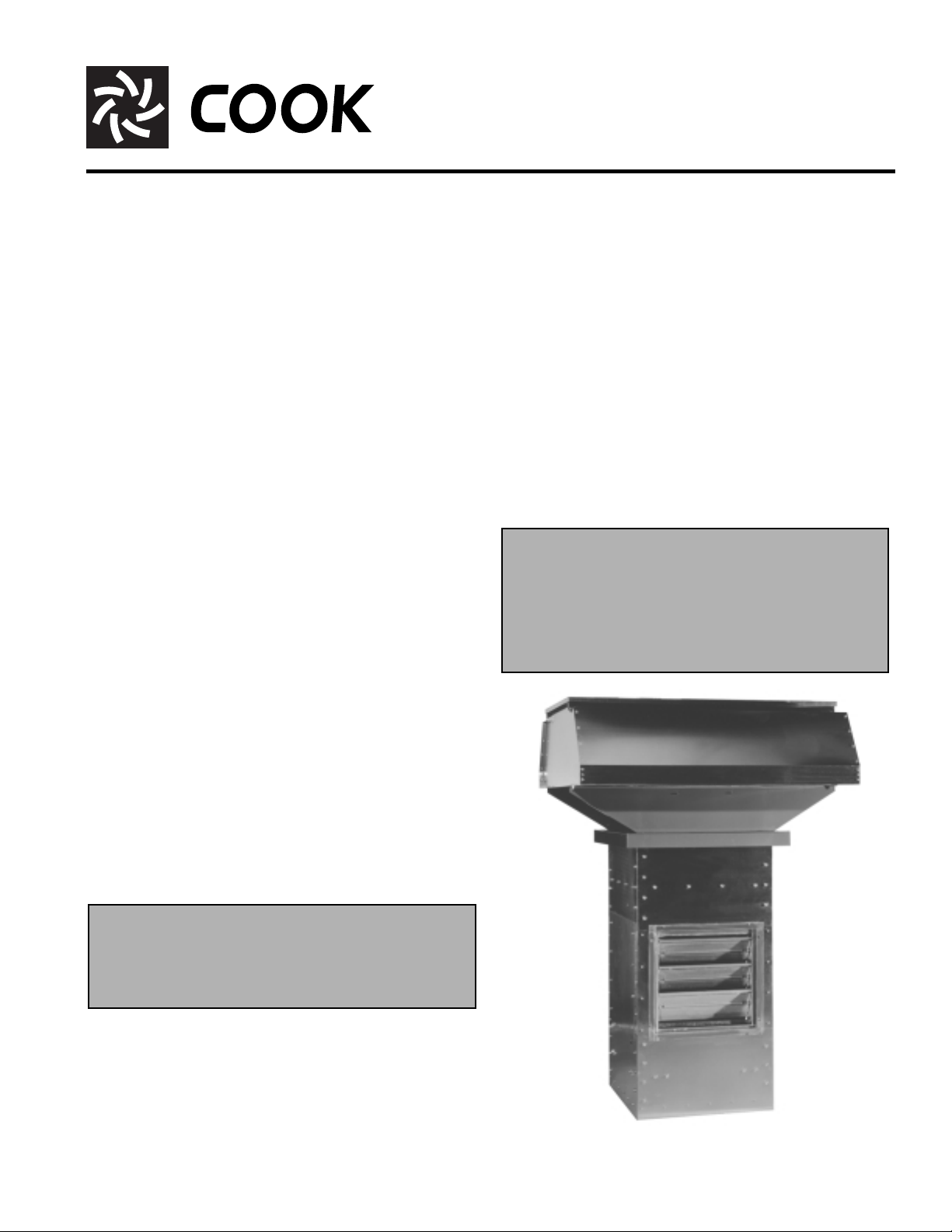
Economizer Fan
Economizer Fans
INSTALLATION, OPERATION AND MAINTENANCE MANUAL
This publication contains the installation, operation
and maintenance procedures for standard units of the
Economizer Fan-Economizer Fans with Mix, Recirculate, Supply and Exhaust Modes
publication prior to installation.
Loren Cook catalog,
information describing the equipment, fan performance,
available accessories and specification data.
For additional safety information, refer to AMCA publication 410-96,
Industrial and Commercial Fans
All of the publications listed above can be obtained from
Loren Cook Company Literature Department by phoning
417/869-6474, extension 166; by FAX at 417/832-9431; or
by e-mail at info@lorencook.com.
For information and instructions on special equipment,
contact Loren Cook Company at (417) 869-6474.
Safety Practices for Users and Installers of
Economizer Fan
. Carefully read this
, provides additional
.
Receiving and Inspection
Carefully inspect the fan and accessories for any damage
and shortage immediately upon receipt of the fan.
The control panel, if ordered, is shipped inside of the
roof base. It is not counted as a separate part.
• Turn the propeller by hand to ensure it turns freely and
does not bind.
• Check the dampers for free operation of all moving
parts.
• Record on the
age.
Delivery Receipt
any visible sign of dam-
Handling
Lifting bars are located on the top of the cabinet assembly. They should be used to lift the unit and also to lower the
unit on to the curb. The hood assembly should be lifted by
the shipping crate or the base assembly.
Storage
If the unit is stored for any length of time prior to installation, store it in its original shipping crate and protect it from
dust, debris and the weather.
through the roof curb until the assembly’s outer flange
rests on the top of the roof curb. The curb should be
level to allow the cabinet to hang free.
c. Assemble the hood to hood base. Refer to
Assembly
d. Lower the hood assembly on to the roof curb and
secure it and the cabinet assembly to the roof curb with
anchor bolts or lag screws as required.
e. Pre-wire the service switch on the roof base, if
equipped.
f. Install the hood assembly filters, if required. Refer to
Filtered Units Only
g. Install the outlet diffuser on the lower end of the cabinet
assembly, if equipped. Place the diffuser over the bottom of the cabinet assembly. Secure the diffuser to the
cabinet with number 12 sheet metal screws installed
through the flange, spaced at 6 inch intervals around
the perimeter.
continued
Personal Safety
Disconnect switches are recommended. Place
the disconnect switch near the fan in order that
the power can be swiftly cut off in case of an
emergency, and in order that maintenance personnel are provided complete control of the
power source.
instructions on page 2.
section on page 2.
Hood
WARNING
This unit has rotating parts. Safety precautions
should be exercised at all times during installation,
operation, and maintenance.
ALWAYS disconnect power prior to working on fan.
Installation
a. Ensure there is a minimum 3 inch clearance between
the interior of the building and the unit’s side dampers.
b. Attach lifting straps to the lifting bars at the top of the
cabinet assembly. Lift the assembly and then lower it
Economizer
Page 2
h. If no outlet diffuser is supplied, install the outlet guard
over the bottom of the cabinet assembly. Secure the
outlet guard to the cabinet with number 12 sheet metal
screws installed through the flange, spaced at 6 inch
intervals around the perimeter.
i. Install the control panel, if equipped, in a convenient
location. Refer to the wiring installation section, page 3
for wiring instructions.
B
A
D
F
E
F
Figure 1
C
B
A
E
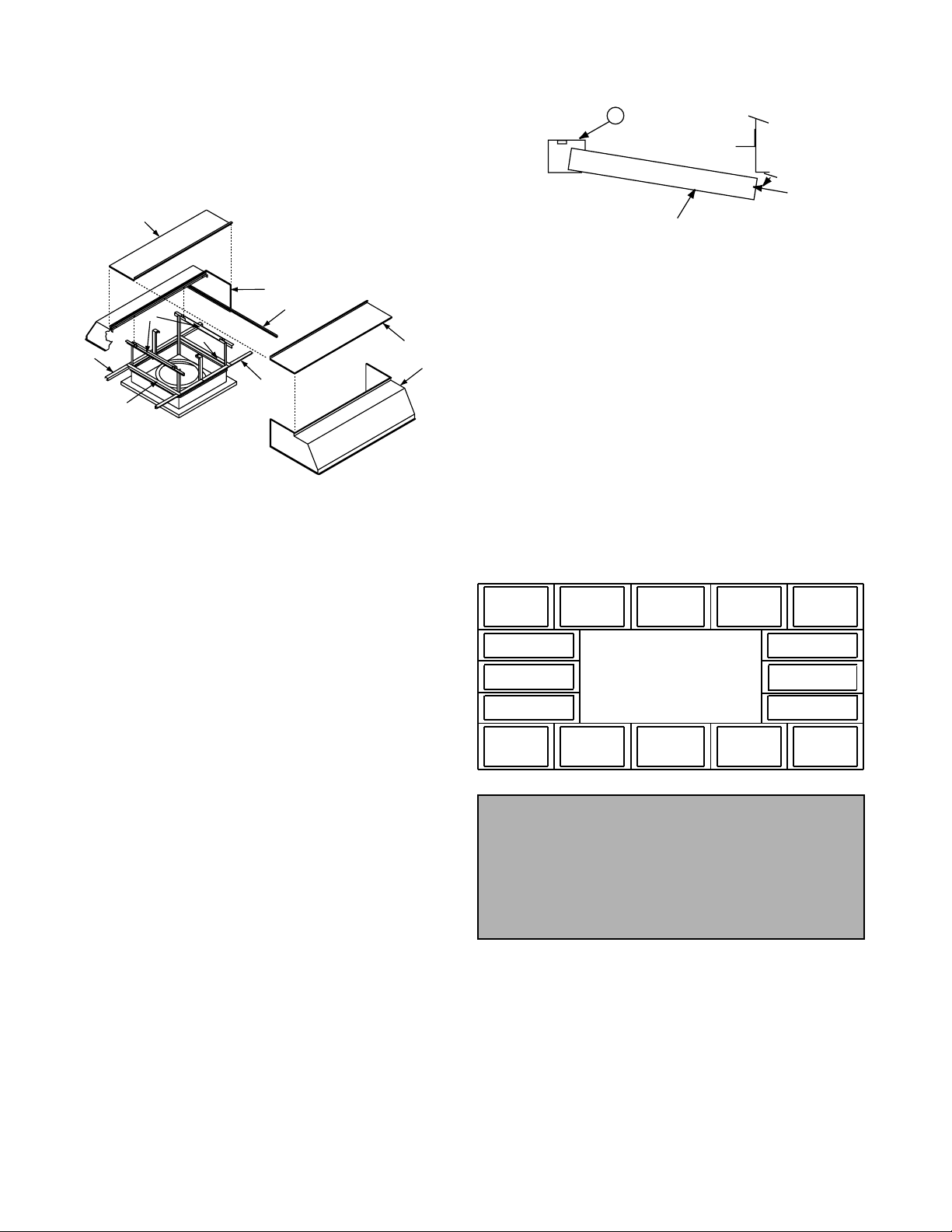
Hood Assembly
Hoods on some non-filtered units (size 54 or larger) and
some filtered units (size 48 or larger) require field assembly.
Assembly is accomplished using 1/2 inch and 9/16 inch
socket wrenches. Line-up punches and hand clamps will
speed up the assembly. Figure 1 shows the components
used to assemble the hood.
a. Place the hood halves (A) onto the hood supports (D).
Line up the hood flanges and bolt the flanges of the
hood ends together. The topcaps (B) must be interlocked for the flanges to meet correctly.
b. Go under the hood and bolt the hood (angle flange) to
the hood supports (D) at the four overlapping locations.
c. Install the two perimeter angles (C) inside each end of
the hood.
d. If there is a gap between the top cap edges, loosen the
top cap bolts. Install a bolt in each end of the top cap
flange to pull the two top caps together. Tighten the top
cap bolts.
Filtered Units Only
e. Place the two long filter retainers (E) and the two short
filter retainers (F) on top of the base and bolt the pieces
together.
f. Bolt the long filter retainers (E) to the perimeter angles
(C) that are at the ends of each hood.
g. Install filters according to the Filter Schedule. Insert the
edge of the filter into the filter retainer (E), swing filter
into position and flip the filter holding the clip into position. Refer to the Filter Installation Detail illustration.
E
Economizer Fan Filter Installation Detail
Control Panel Installation
(if equipped)
The optional control panel is used to control the functions
of the Economizer fan. Locate the panel in a convenient
area to install wiring and operate the fan. Permanently
attach the control panel to a suitable structure by bolting
through the back of the panel.
Temperature Sensor Installation
(if equipped)
A temperature sensor is supplied as a part of the optional
Modulating Temperature Control. To prevent damage to the
fan during transit, the temperature sensor is shipped loose
(inside the control panel). Follow the instructions below to
mount the temperature sensor.
a. Drill a 11/32 inch diameter hole in one corner of the
venturi panel, located in the bottom of the fan cabinet.
b. From the inside of the cabinet, screw the compression
fitting (shipped with the sensor) into the hole.
c. Install the sensor through the hole (push through 1/2”).
d. Tighten the fitting to hold the sensor in place.
Type 2
Type 1
Type 1
Type 1
Type 2 Type 2 Type 2 Type 2 Type 2
Type 2
Type 2
Economizer Fan
Filter Schedule
Type 2 Type 2
Type 1
Type 1
Type 1
Personal Safety
Disconnect switches are recommended. Place
the disconnect switch near the fan in order that
the power can be swiftly cut off in case of an
emergency, and in order that maintenance personnel are provided complete control of the
power source.
Follow the wiring diagram in the disconnect switch
and the wiring diagram provided with the motor.
2
Page 3
Wiring Installation
All wiring should be in accordance with local ordinances
and the National Electrical Code, NFPA 70. Ensure the
power supply (voltage, frequency, and current carrying
capacity of wires) is in accordance with the motor nameplate. Refer to the
Wiring Diagram
, below.
Fan accessories will determine the wiring installation
procedure you should follow. If your unit has a disconnect
switch, follow the wiring diagram provided on the disconnect switch and the wiring diagram on the motor. Correctly
label the circuit on the main power box and always identify
a closed switch to promote safety (i.e. red tape over a
closed switch).
Lock off all power sources before unit is wired to
power source. Restrain the wire as necessary to prevent it from being pulled into any rotating parts.
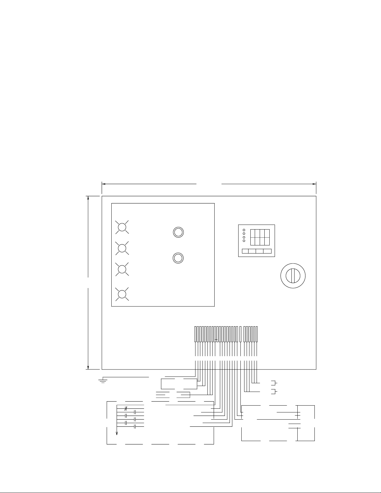
Control Panel Wiring Diagram
Lights
on Door
Supply
Fan Wiring
Drill a wire access hole through the cabinet side below
one of the access doors. Attach the appropriate size wire
and conduit to the motor and run the wires to the control
panel. Attach wires (18 gauge minimum) to the damper
actuator (Red, Black, #3) and the temperature sensor (Red,
2-Black), if equipped, and run the wires to the control
panel. Attach the fan wires to the control panel terminals
according the diagram below.
A terminal (1) is available for use with remote stop controls. Closing a relay between terminals 1 and 5 will do the
same function as pushing the stop button on the front of the
panel.
Wire the roof disconnect switch, if equipped, and the fan
motor. The fan should rotate clockwise, when looking up
from the bottom, in supply mode. The rotation may be
changed by switching two of the three motor leads. When
rotation is correct, reinstall the access panels.
20"
Optional
Modulating Temperature Control
16"
Start/Mode
Red
Red
Button
Stop
Button
Neutral
120VAC
G
N
N
Mix
Recirculate
Exhaust (MRSE-D Only)
Ground
No Field
Connection
RTD (Optional)
24 VDC +
24 VDC Remote Cool Thermostat
24 VDC Remote "Supply On"
24 VDC Remote "Mix On"
24 VDC Remote "Recirculate On"
24 VDC Remote "Exhaust On"
24 VDC Remote "Stop"
Customer Supplied Controls For External Input
White
3
R
45
R
L
W
2
678910
1
L
TT
ABCT
Load
Fan Motor
Line
Fan Voltage
5VDC-10VDC POS
24VAC COM / 5VDC-10VDC
24VAC
Damper Actuator Connections
NC
NC
3
Black
Red
4
5
3
Page 4

Final Installation Steps
a. Check and tighten fasteners and setscrews, particu-
larly unit mounting fasteners. Tighten according to the
recommended torque shown in table
Torque for Setscrews/Bolts
..
Recommended
b. Check for correct voltage with voltmeter.
c. Ensure all accessories are installed.
Recommended Torque for Setscrews/Bolts
Setscrews
Size
No.10 3/32” 28 33 3/8”-16 240
1/4” 1/8” 66 80 1/2”-13 600
5/16” 5/32” 126 156 5/8”-11 1200
3/8” 3/16” 228 275 3/4”-10 2100
7/16” 7/32” 348 384 7/8”-9 2040
1/2” 1/4” 504 600 1”-8 3000
5/8” 5/16” 1104 1200 1-1/8”-7 4200
3/4” 3/8” 1440 1800 1-1/4”-7 6000
Key Hex
Across
Flats
Recommended
Torque
Min. Max. Size
Hold Down Bolts
Wrench
Torque
Operation
Pre-Start Checks
a. Lock out all the primary and secondary power sources.
b. Check and tighten fasteners and setscrews, particu-
larly those used for mounting the unit.
c. Check motor wiring.
d. Rotate the prop to ensure it does not rub against the
venturi.
e. Ensure fan and ductwork are clean and free of debris.
f. Close and secure all access doors.
g. Restore power to unit.
There are four basic designs for the operation control
panel on this unit. They are defined by whether or not the
fan unit is reversible, and whether or not the mix mode is
supplied with a temperature control and modulating dampers.
Modes
MRS-D - mix, recirculate, supply.
MRS-D with Modulating Temperature Controller - mix
dependent upon fan outlet temperature, recirculate, supply.
MRSE-D - mix, recirculate, supply, exhaust.
MRSE-D with Modulating Temperature Controller -
mix dependent upon fan outlet temperature, recirculate,
supply, exhaust.
The function pad on the front of the control panel contains two operators - a Start/Mode button and a Stop button.
When the Start/Mode button is depressed, the top mode
light will start to flash. This light will flash for 3 seconds to
indicate that a mode is ready to begin. If the mode button is
pressed again within the 3 second delay, the next mode
light will begin to flash. If the mode light is allowed to flash
for the full 3 seconds, the light will then stay on and the fan
will start.
If the panel contains a temperature controller, this module will be powered only during mix mode. The display on
the temperature controller indicates the outlet temperature
of the fan and the set value which it is trying to produce by
mixing outside air and inside air. The set value temperature
must be between the indoor and outdoor temperatures in
order for the fan to match the set value. Refer to the Control
Panel for programming instructions to set the value temperature.
If the operating mode is changed, such that the direction
of the propeller rotation must change, there will be a 30
second spin down delay before the start of the new mode.
Start-Up
Turn fan on in supply mode. Inspect for the following:
• Direction of rotation.
• Excessive vibration.
• Unusual noise.
• Improper motor amperage or voltage.
If a problem is discovered, immediately shut the fan
off. Lock out all electrical power and check for the
cause of the trouble. Refer to
Troubleshooting,
page 5
Inspection
Inspection of the fan should be conducted at the first 30
minute, 8 hour and 24 hour intervals of satisfactory opera-
tion. During the inspections, stop the fan and inspect as
instructed.
30 Minute Interval
Inspect bolts, setscrews, and motor mounting bolts.
Adjust and tighten as necessary.
8 Hour Interval
Inspect bolts, setscrews, and motor mounting bolts.
Adjust and tighten as necessary.
24 Hour Interval
Inspect bolts, setscrews, and motor mounting bolts.
Adjust and tighten as necessary.
Maintenance
Establish a schedule for inspecting all rotating parts. The
frequency of inspection depends on the operating conditions and location of the fan.
Inspect fans exhausting corrosive air within the first
month of operation.
Yearly inspections are recommended for fans exhausting
non-contaminated air.
It is recommended that inspection of the unit be conducted twice annually.
• Inspect bolts and setscrews for tightness. Tighten as
necessary. Refer to
Torque chart
• Inspect for cleanliness. Clean exterior surfaces only.
Removing dust and grease build-up on motor housing
assures proper motor cooling.
.
.
4
Page 5

Clean the propeller and air inlets if material build-up is
excessive. Excessive build-up can cause imbalance and
failure of the propeller. When cleaning the propeller, always
clean the entire propeller. Partial cleaning will cause imbalance and will lead to unit failure.
Filters
Filters should be checked within the first two weeks of
operation. If there is no excessive build-up, monthly servicing should be adequate.
To clean reusable aluminum filters, back flush with soap
and water. When clean, shake off excess water and allow
the filter to air-dry before reinstalling it.
Please note the following tables concerning filter sizes.
Economizer Fan Filter Sizes
Unit Type 1 Type 2
Size Length x Width
24 18-1/4” x 30-1/8” 2 18-1/4” x 33-1/4” 4
30 20-7/16” x 18-1/16” 4 20-7/16” x 25-13/16” 6
36 22-1/4” x 21-1/16” 4 22-1/4” x 29-5/32 6
42 24-1/16” x 29-1/2” 4 26-7/8” x 19-1/4” 6
48 27” x 27” 4 27” x 27” 8
54 29-1/8” x 19-3/8” 6 29-1/8” x 23-5/8” 10
60 37-7/8” x 21-7/8 6 26” x 28-9/16” 10
No.
Req’d
Length x Width
No.
Req’d
Motor Bearings
Motor bearings are pre-lubricated and sealed. Under
normal conditions they will not require further maintenance
for a period of ten years. However, it is advisable to have
your maintenance department remove and disassemble
the motor, and lubricate the bearings after three years of
operation in excessive heat and or in a contaminated airstream consisting of airborne abrasives.
Motor Services
Should the motor prove defective within a one-year
period, contact your local Loren Cook Company representative or your nearest authorized electric motor service representative.
Troubleshooting
Problem and Potential Cause
Low Capacity or Pressure
•Incorrect direction of rotation. Make sure the fan rotates in same direction as the arrows on the motor or belt drive assembly.
•Poor fan inlet conditions. There should be a straight clear duct at the
inlet.
•Improper propeller alignment.
Excessive Vibration and Noise
•Damaged or unbalanced propeller.
•Belts too loose; worn or oily belts.
•Speed too high.
•Incorrect direction of rotation. Make sure the fan rotates in same direction as the arrows on the motor or belt drive assembly.
•Bearings need lubrication or replacement.
•Fan surge.
Overheated Motor
•Motor improperly wired.
•Incorrect direction of rotation. Make sure the fan rotates in same direction as the arrows on the motor or belt drive assembly.
•Cooling air diverted or blocked.
•Improper inlet clearance.
•Incorrect fan RPMs.
•Incorrect voltage.
Overheated Bearings
•Improper bearing lubrication
•Excessive belt tension.
5
Page 6

Economizer Hood Replacement Parts List
3
2
4
10
9
1
11
3
2
9
5
6
5
8
7
4
Number Required
Part No. Description
24 30 36 42 48 54 60 24 30 36 42 48 54 60
1 Perimeter Angle ----4444444448
2 Angle Support ----444---4444
3 Top Cap 11222221222222
4 Hood 11112221112222
5 Filter Rack -------2222224
6 Filter Crossmember -------2222222
7 Corner Post 4444444- - - 4444
8 Base Assembly 11111111111111
9 Hood Support -----22----222
10 Hood Support Angle ----222---2224
11 Center Post -------------2
Parts Not Illustrated
Filters (MRSF only) - - - - - - - - - - - - - - 6 10 10 10 12 16 16
Filter Retainer Clips (MRSF only) - - - - - - - - - - - - - - 12 20 20 20 24 32 32
Non-Filtered Filtered
6
Page 7

Economizer Cabinet Parts List
7
1
2
3
12
11
10
9
Part
No.
1 Upper Cabinet Assembly
2 Top Damper
3 Top Damper Support (4)
4 Corner Posts (4)
5 Access Door (2)
6 Access Door Mount (4)
7 Motor Plate
8 Lower Cabinet/Power Assembly
9 Diffuser Panel (optional)
10 Motor
11 Side Damper Mount (4)
12 Side Damper (2)
13 Extruded Propeller (not shown)
Description
4
5
6
7
8
Page 8

Limited Warranty
Loren Cook Company warrants that your Loren Cook fan was manufactured free of defects in materials and workmanship, to the extent stated herein. For a period of one (1)
year after date of shipment, we will replace any parts found to be defective without charge, except for shipping costs which will be paid by you.
This warranty is granted only to the original purchaser placing the fan in service.
This warranty is void if the fan or any part thereof has been altered or modified from its original design or has been abused, misused, damaged or is in worn condition or if
the fan has been used other than for the uses described in the company manual. This warranty does not cover defects resulting from normal wear and tear.
To make a warranty claim, notify Loren Cook Company, General Offices, 2015 East Dale Street, Springfield, Missouri 65803-4637, explaining in writing, in detail, your complaint and referring to the specific model and serial numbers of your fan. Upon receipt by Loren Cook Company of your written complaint, you will be notified, within thirty (30)
days of our receipt of your complaint, in writing, as to the manner in which your claim will be handled. If you are entitled to warranty relief, a warranty adjustment will be completed within sixty (60) business days of the receipt of your written complaint by Loren Cook Company.
This warranty gives only the original purchaser placing the fan in service specifically the right. You may have other legal rights which vary from state to state.
Corporate Offices: 2015 E. Dale Street Springfield, MO 65803 417.869.6474
www.lorencook.com
Economizer IOM -March 1998
 Loading...