

Page 1
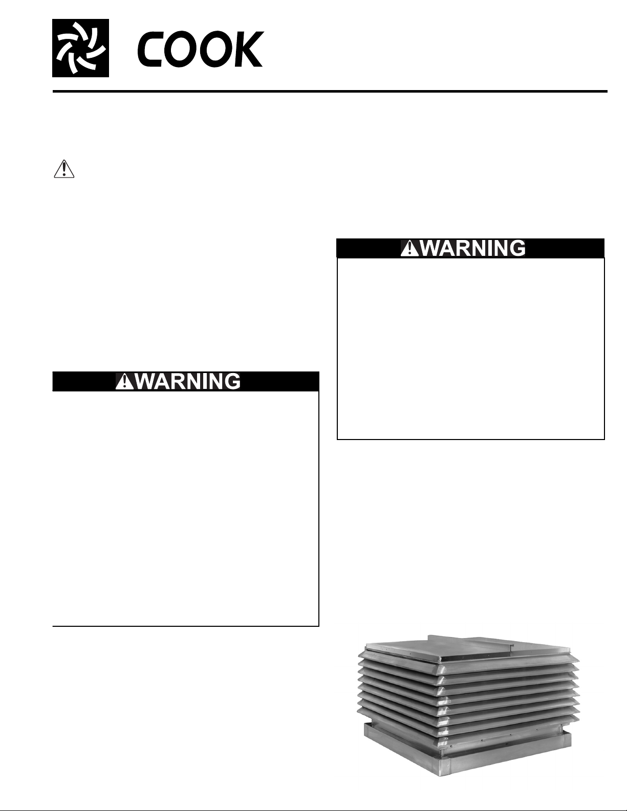
CFS
Centrifugal Filtered Supply Fans
INSTALLATION, OPERATION, AND MAINTENANCE MANUAL
This publication contains the installation, operation and
maintenance instructions for standard units of the CFS
Centrifugal Filtered Supply Fans. Carefully read this publication prior to any installation or maintenance procedure.
Carefully read this publication and any supplemental documents prior to any installation or
maintenance procedure.
Loren Cook catalog, CFS, provides additional information
describing the equipment, fan performance, available
accessories, and specification data.
For additional safety information, refer to AMCA publication 410-96, Safety Practices for Users and Installers of
Industrial and Commercial Fans.
All of the publications listed above can be obtained from
Loren Cook Company by phoning 417/869-6474, extension
166; by FAX at 417/832-9431; or by e-mail at info@lorencook.com.
For information on special equipment, contact Loren
Cook Company Customer Service Department at 417/869-
6474.
Rotating Parts & Electrical Shock Hazard:
Disconnect electric power before working on unit.
Follow proper lockout / tagout procedures to ensure
the unit cannot be energized while being installed or
serviced.
A disconnect switch should be placed near the fan in
order that the power can be swiftly cut off, in case of
an emergency and in order that maintenance
personnel are provided complete control of the power
source.
Grounding is required. All field-installed wiring must
be completed by qualified personnel. All fieldinstalled wiring must comply with National Electric
Code (NFPA 70) and all applicable local codes.
Failure to follow these instructions could result in
death or serious injury.
lifting eyes on the housing. NOTICE! Never lift by the
shaft, motor, or tiers.
Storage
If the fan is stored for any length of time prior to installation, completely fill the bearings with grease or moistureinhibiting oil (refer to Lubricants on page 5). Rotate the
wheel several revolutions every three to five days to keep a
coating of grease on all internal bearing parts.
Store the fan in its original crate and protect it from dust,
debris and the weather.
The attachment of roof mounted fans to the roof curb
as well as the attachment of roof curbs to the building
structure must exceed the structural requirements
based on the environmental loading derived from the
applicable building code for the site. The local code
official may require variations from the recognized
code based on local data. The licensed engineer of
record will be responsible for prescribing the correct
attachment based on construction materials, code
requirements and environmental effects specific to
the installation.
Failure to follow these instructions could result in
death or serious injury.
Installation
Motor Installation
Most motors are shipped on the fans with belts and drives
installed. However, extremely heavy motors and drives are
shipped separately. These motors and drives will require
field installation. Please refer to page 4.
Duct Installation
Efficient fan performance relies on the proper installation
of inlet and discharge ducts. Be sure your fan conforms to
the following guidelines.
Receiving and Inspection
Carefully inspect the fan and accessories for any dam-
age and shortage immediately upon receipt of the fan.
• Turn the wheel by hand to ensure it turns freely and
does not bind.
• Inspect dampers (if supplied) for free operation of all
moving parts.
• Record on the Delivery Receipt any visible sign of
damage.
Handling
Lift the fan by the base or remove the lid and lift by the
CFS
Page 2
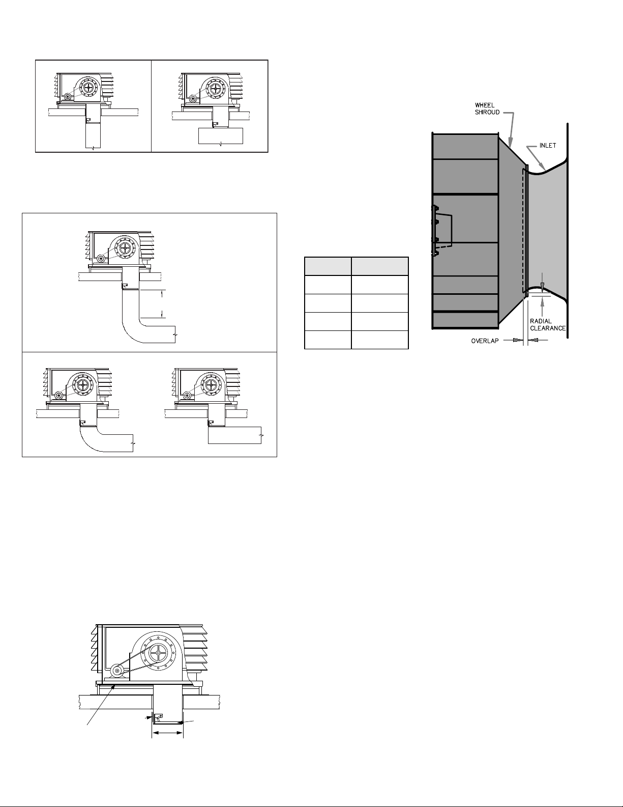
Free Discharge
Avoid a free discharge into the plenum. This will result in
lost efficiency because it doesn’t allow for a static regain.
Correct
Incorrect
Discharge Duct Turns
Where possible, allow 3 duct diameters between duct
turns or elbows and the fan outlet. Refer to Discharge Duct
Turns drawing on Page 2.
Correct
MIN
3 DIA.
Wheel-to-Inlet Clearance
The correct wheel-to-inlet clearance is critical to proper
fan performance. This clearance should be verified before
initial start-up since rough handling during shipment could
cause a shift in fan components. Refer to wheel/inlet drawing for correct overlap.
Adjust the overlap by
loosening the wheel hub
and moving the wheel along
the shaft to obtain the correct value.
A uniform radial gap
(space between the edge of
the cone and the edge of
the inlet) is obtained by
loosening the inlet cone
bolts and repositioning the
inlet cone.
Size Overlap
100 - 165 3/16”
180 - 245 1/4”
270 - 300 5/16”
Incorrect
Damper and Curb Installation
a. Minimum roof opening dimensions can be found
within the CFS catalog.
b. The optional duct adapter fits on the curb to locate the
top of the duct before the fan is installed. Ductwork
requires additional support.
c. The typical damper try (optional) extends below the
curb top 38 inches. A clear 17-1/2 inches is required
to access the damper tray panel (see drawing above).
Should a longer damper tray be required, extended
lengths are available.
NOTICE! It may be necessary to add support beneath
the load carrying sides of the blower and curb.
Duct Adapter
Damper and Curb Installation Components
Damper Tray
Minimum
Roof Opening
Motorized
Intake Damper
330 - 365 3/8”
Use of Variable Frequency Drives
Motors -
Motors that are to be operated using a Variable Frequency Drive (VFD) must be VFD compatible. At a minimum, this must be a Premium Efficiency motor with Class F
insulation. Motors that are not supplied by Loren Cook
Company should have the recommendation of the motor
manufacturer for use with a VFD.
Grounding -
The fan frame, motor and VFD must be connected to a
common earth ground to prevent transient voltages from
damaging rotating elements.
Wiring -
Line reactors may be required to reduce over-voltage
spikes in the motors. The motor manufacturer should be
consulted for recommended line impedence and usage of
line reactors or filters, if the lead length between the VFD
and the motor exceeds 10 feet (3m).
Fan -
It is the responsibility of the installing body to perform
coast-down tests and identify any resonant frequencies
after the equipment is fully installed. These resonant frequencies are to be removed from the operating range of
the fan by using the “skip frequency” function in the VFD
programming. Failure to remove resonant frequencies
from the operating range will decrease the operating life of
the fan and void the warranty.
Wiring Installation
All wiring should be in accordance with local ordinances
and the National Electrical Code, NFPA 70. Ensure the
power supply (voltage, frequency, and current carrying
capacity of wires) is in accordance with the motor nameplate.
2
Page 3
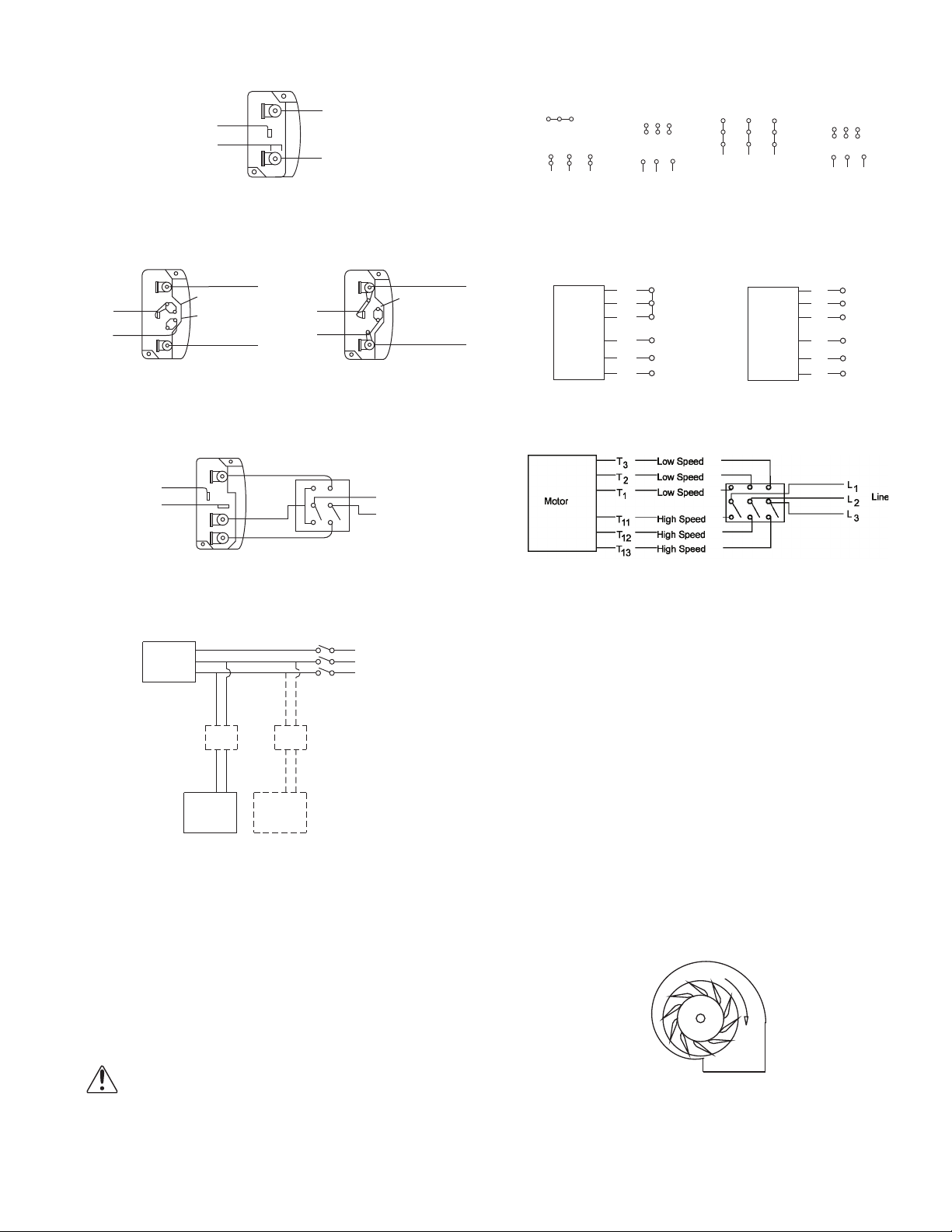
Wiring Diagrams
Single Speed, Single Phase Motor
Ground A
L
T-1
T-4
Ground B
When ground is required, attach to ground A or B with no. 6 thread forming
screw. To reverse, interchange T-1 and T-4.
1
Line
L
2
Wiring Diagrams
3 Phase, 9 Lead Motor
Y-Connection
Low Voltage
208/230 Volts
4
5
6
3
1
9
728
L2L
L
1
3
High Voltage
460 Volts
456
789
3
12
L2L
L
1
To reverse, interchange any 2 line leads.
3 Phase, 9 Lead Motor
Delta-Connection
Low Voltage
208/230 Volts
L
1
3
High Voltage
7
6
1
5
4
3
2
L
L
3
2
9
8
460 Volts
789
456
12
L1L
L
2
3
3
2 Speed, 2 Winding, Single Phase Motor 2 Speed, 1 Winding, 3 Phase Motor
Ground A
L
T-5
J-10
Link A
Link B
Low Voltage
Ground B
Line
L
1
T-5
J-10
2
Ground B
When ground required, attach to ground A or B with No. 6 thread forming
screw. To reverse, interchange T-1 and T-4 leads.
Ground A
Link A & B
L
Line
L
High Speed
1
Motor
2
1
Together
2
3
L
4
1
L
5
2
6
Line
L
3
Low Speed
Motor
To reverse, interchange any 2 line leads. Motors require magnetic control.
Single Speed, Single Phase, Dual Voltage 2 Speed, 2 Winding, 3 Phase
Ground A
T-1
T-4
Ground B
When ground required, attach to ground A or B with No. 6 thread forming
screw. To reverse, interchange T-5 and J-10 leads. To reverse: High Speed-interchange leads T11 and T12.
High Speed
Low Speed
L
1
Line
L
2
Low Speed-interchange leads T1 and T2. Both Speeds-interchange any 2
Typical Damper Motor Schematic
Fan
Motor
Transformer**
L3
L2
L1
Transformer**
For 3 phase, damper motor voltage should be the same between L1 and L2. For
single phase application, disregard L3. * Damper motors may be available in 115,
230 or 460 volt models. The damper motor nameplate voltage should be verified
prior to connection. ** A transformer may be provided in some installations to correct the damper motor voltage to the specified voltage.
L
1
1
L
2
2
3
Line
L
3
4
Open
5
6
Damper
Motor*
Second
Damper
Motor
Lock off all power sources before unit is wired to
power source.
Leave enough slack in the wiring to allow for motor
movement when adjusting belt tension. Some fractional motors have to be removed in order to make
the connection with the terminal box at the end of the
motor. To remove motor, remove bolts securing
motor base to power assembly. Do not remove motor
mounting bolts.
Follow the wiring diagram in the disconnect switch and the wiring diagram provided with the motor. Correctly label the
circuit on the main power box and always
identify a closed switch to promote safety
(i.e., red tape over a closed switch).
Wheel Rotation
Test the fan to ensure the rotation of the wheel is the
same as indicated by the arrow marked Rotation.
Airfoil
Proper Wheel Rotation
3
Page 4
115 and 230 Single Phase Motors
1 foot
1/4 inch
Fan wheel rotation is set correctly at the factory. Changing the rotation of this type of motor should only be
attempted by a qualified electrician.
208, 230, and 460, 3 Phase Motors
These motors are electrically reversible by switching two
of the supply leads. For this reason, the rotation of the fan
cannot be restricted to one direction at the factory. See
Wiring Diagrams on page 3 for specific information on
reversing wheel direction.
NOTICE! Do not allow the fan to run in the wrong
direction. This will overheat the motor and cause serious damage. For 3-phase motors, if the fan is running
in the wrong direction, check the control switch. It is
possible to interchange two leads at this location so
that the fan is operating in the correct direction.
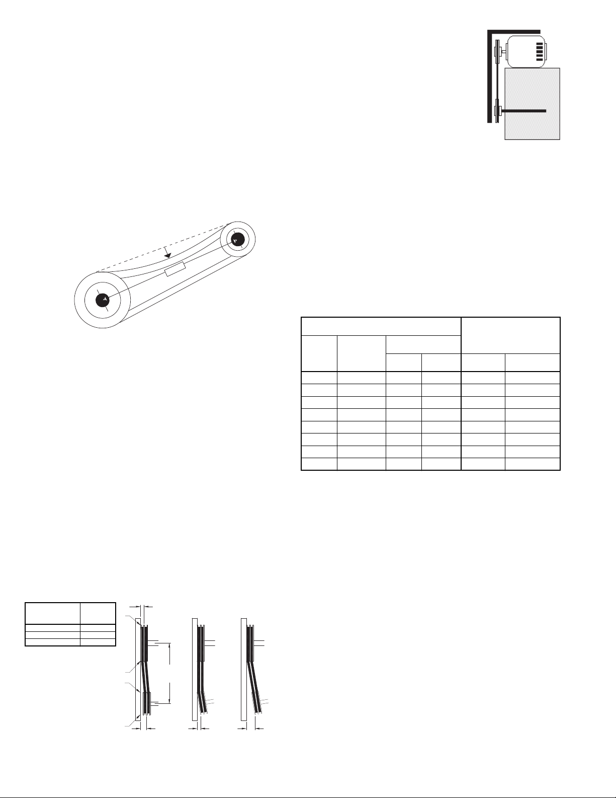
Figure 3
Belt and Pulley Installation
Belt tension is determined by the sound the belts make
when the fan is first started. Belts will produce a loud
squeal which dissipates after the fan is operating at full
capacity. If the belt tension is too tight or too loose, lost efficiency and possible damage can occur.
Do not change the pulley pitch diameter to change tension. This will result in a different fan speed than desired.
a. Loosen motor plate adjustment bolts and move motor
in order that the belts can easily slip into the grooves
on the pulleys. Never pry, roll, or force the belts over
the rim of the pulley.
b. Adjust the motor back until proper tension is reached.
For proper tension a deflection of approximately 1/4”
per foot of center distance should be obtained by
firmly pressing the belt. Refer to figure 3.
c. Tighten the motor base nuts.
d. Ensure pulleys are properly aligned. Refer to Figure 4.
Tolerance
Center Distance
Up thru 12” 1/16”
12” up through 48 1/8”
Over 48” 1/4”
Maximum
Gap
OFFSET ANGULAR OFFSET/ANGULAR
A
W
X
Y
CENTER
DISTANCE
(CD)
Pulley Alignment
Pulley alignment is adjusted by loosening the motor pulley setscrew and by
moving the motor pulley on the motor
shaft.
Figure 4 indicates where to measure
the allowable gap for the drive alignment
tolerance. All contact points (indicated
by WXYZ) are to have a gap less than
the tolerance shown in the table. When
the pulleys are not the same width, the
Figure 5
allowable gap must be adjusted by half of the difference in
width (As shown in A & B of Figure 4). Figure 5 illustrates
using a carpenter’s square to adjust the position of the
motor pulley until the belt is parallel to the longer leg of the
square.
Final Installation Steps
a. Inspect fasteners and setscrews, particularly fan
mounting and bearing fasteners, and tighten according to the recommended torque shown in the table
Recommended Torque for Setscrews/Bolts.
b. Inspect for correct voltage with voltmeter.
c. Ensure all accessories are installed.
Recommended Torque for Setscrews/Bolts (IN/LB.)
Setscrews
Size
No.10 3/32” 28 33 3/8”-16 240
1/4” 1/8” 66 80 1/2”-13 600
5/16” 5/32” 126 156 5/8”-11 1200
3/8” 3/16” 228 275 3/4”-10 2100
7/16” 7/32” 348 384 7/8”- 9 2040
1/2” 1/4” 504 600 1”- 8 3000
5/8” 5/16” 1104 1200 1-1/8” - 7 4200
3/4” 3/8” 1440 1800 1-1/4” - 7 6000
Key Hex
Across
Flats
Recommended
Torque
Min. Max. Size
Hold Down Bolts
Wrench
Torque
Operation
Pre-Start Checks
a. Lock out all the primary and secondary power
sources.
b. Ensure fasteners and setscrews, particularly those
used for mounting the fan, are tightened.
c. Inspect belt tension and pulley alignment.
d. Inspect motor wiring.
e. Ensure belt touches only the pulleys.
f. Ensure fan and ductwork are clean and free of debris.
g. Inspect wheel-to-inlet clearance. The correct wheel-
to-inlet clearance is critical to proper fan performance.
h. Close and secure all access doors.
i. Restore power to the fan.
Figure 4
Z
B
GAP
GAP
4
Page 5
Start Up
Turn the fan on. In variable speed units, set the fan to its
lowest speed and inspect for the following:
• Direction of rotation.
• Excessive vibration.
• Unusual noise.
• Bearing noise.
• Improper belt alignment or tension (listen for squealing).
• Improper motor amperage or voltage.
NOTICE! If a problem is discovered, immediately
shut the fan off. Lock out all electrical power and check
for the cause of the trouble. See Troubleshooting.
Inspection
Inspection of the fan should be conducted at the first 30
minute, 8 hour and 24 hour intervals of satisfactory opera-
tion. During the inspections, stop the fan and inspect as per
the Conditions Chart.
30 Minute Interval
Inspect bolts, setscrews, and motor mounting bolts.
Adjust and tighten as necessary.
8 Hour Interval
Inspect belt alignment and tension. Adjust and tighten as
necessary.
24 Hour Interval
Inspect belt tension, bolts, setscrews, and motor mounting bolts. Adjust and tighten as necessary.
Filters
Filter inspection and cleaning intervals can vary from
once a week to twice per year depending on contaminant
present and acceptable pressure drops across the filter.
Under most conditions filters may be cleaned with hot
water and a mild soap solution (such as dish washing liquid) or steam. Some caustic cleaners will damage the filter.
If in doubt, please consult the factory for a compatibility list.
High pressure spray washers should be limited to
2,000psi operating pressure. Every attempt should be
made to remove the contaminants from the filter in a “backwash” flow (note airflow arrow on the filter frame). Once the
filter is dry, it may be returned to the appropriate filter racks
in the same orientation (airflow direction) as they were
removed.
Maintenance
Establish a schedule for inspecting all parts of the fan.
The frequency of inspection depends on the operating conditions and location of the fan.
It is recommended the following inspection be conducted
twice per year.
• Inspect bolts and setscrews for tightness. Tighten as
necessary. Worn setscrews should be replaced immediately.
• Inspect belt wear and alignment. Replace worn belts
with new belts and adjust alignment as needed. Refer
to Belt and Pulley Installation, page 3.
• Bearings should be inspected as recommended in the
Conditions Chart.
• Inspect variable inlet vanes for freedom of operation
and excessive wear. The vane position should agree
with the position of the control arm. As the variable inlet
vanes close, the entering air should spin in the same
direction as the wheel.
• Inspect springs and rubber isolators for deterioration
and replace as needed.
• Inspect for cleanliness. Clean exterior surfaces only.
Removing dust and grease on motor housing assures
proper motor cooling. Removing dirt from the wheel
and housing prevent imbalance and damage.
Lubrication - Fan Bearings
Bearings are lubricated through a grease fitting on the
exterior of the fan housing and should be lubricated by the
schedule, Lubrication Conditions Chart.
For best results, lubricate the bearing while the fan is in
operation. Pump grease in slowly until a slight bead forms
around the bearing seals. Excessive grease can burst
seals thus reducing bearing life.
Before lubricating, the grease nipple and immediate
vicinity should be thoroughly cleaned without the use of
high pressure equipment. The grease should be supplied
slowly as the bearing rotates until fresh grease slips past
the seal. Excessive pressure should be avoided to prevent
seal damage.
Use no more than three injections with a hand-operated
grease gun.
Exceptions to the greasing interval chart:
• Periodic Applications (any break of one week or
more): it is recommended that full lubrication be performed
prior to each break in operation.
• Higher Temperature: it is recommended to halve the
intervals for every 30F increase in operating temperature
above 120F not to exceed 230F for standard bearings;
High Temperature bearings (optional) can operate up to
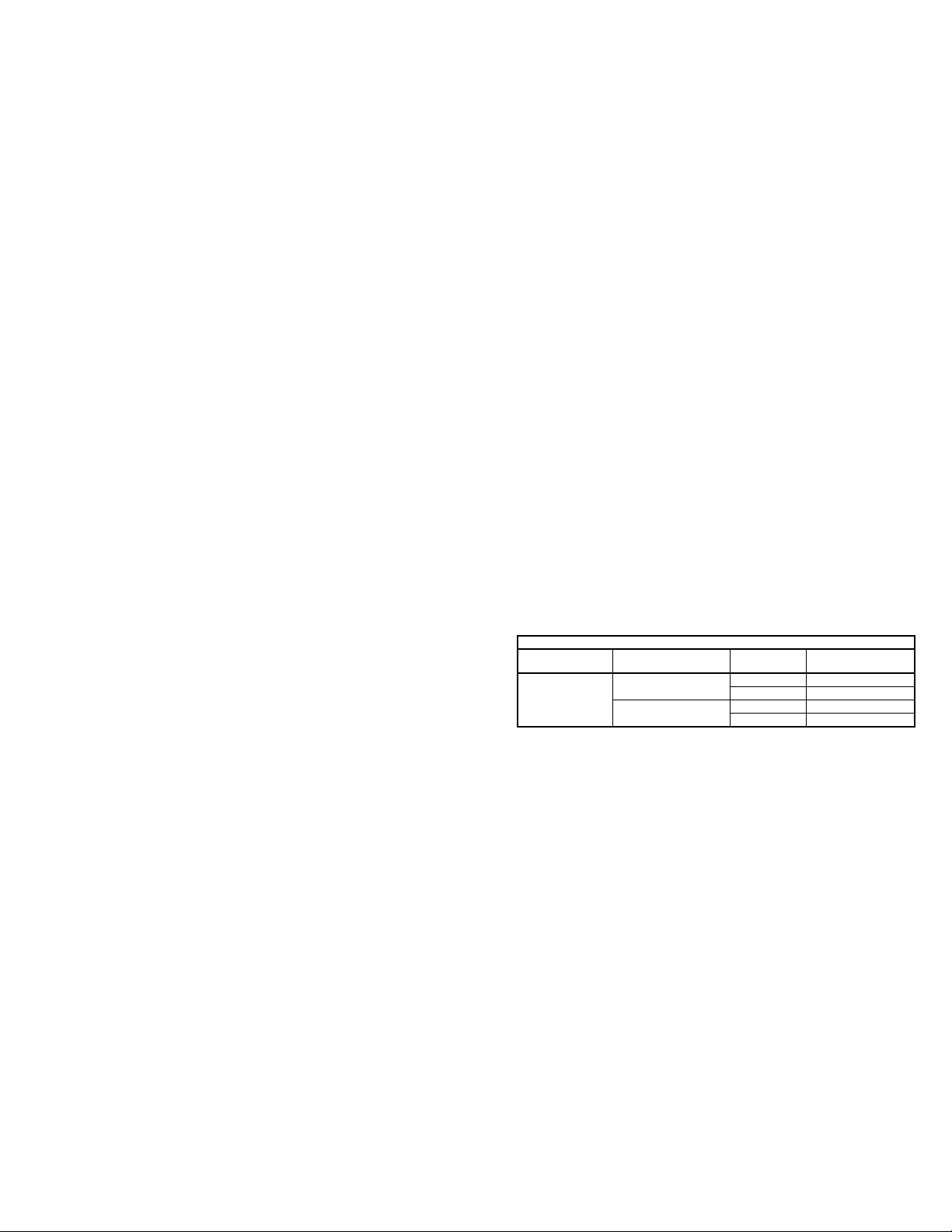
Lubrication Conditions Chart
Fan Class Fan Status Shaft Size
Normal Conditions
Centrifugal Blower
Class I
(Clean, Dry & Smooth)
Extreme Conditions
(Dirty/Wet/Rough)
> 1-1/2” 10,000
< 1-1/2” 2,000
> 1-1/2” 2,000
< 1-1/2” 400
Maximum Interval
(operational hrs)
400F.
Loren Cook Company uses petroleum lubricant in a lithium base. Other types of grease should not be used unless
the bearings and lines have been flushed clean. If another
type of grease is used, it should be a lithium-based grease
conforming to NLGI grade 2 consistency.
A NLGI grade 2 grease is a light viscosity, low-torque,
rust-inhibiting lubricant that is water resistant. Its temperature range is from -30F to +200F and capable of intermittent highs of +250F.
Lubrication - Motor Bearings
Motors are provided with prelubricated bearings. Any
lubrication instructions shown on the motor nameplate
supersede instructions below. Motor bearings without provisions for relubrication will operate up to 10 years under
normal conditions with no
maintenance. In severe applications, high temperatures or
excessive contaminates, it is advisable to have the maintenance department disassemble and lubricate the bearings
after 3 years of operation to prevent interruption of service.
5
Page 6

For motors with provisions for relubrication, follow inter-
vals of the table below.
Relubrication Intervals
NEMA Frame Size
Service
Conditions
Standard 3 yrs. 6 months 2 yrs. 6 months 1 yr. 3 months
Severe 1 yr. 3 months 1 yr. 3 months 6 months 1 months
Up to and
including 184T
1800 RPM
and less
Over 1800
RPM
213T-365T 404T and larger
1800 RPM
and less
Over 1800
RPM
1800 RPM
and less
Over 1800
RPM
Motors are provided with a polyurea mineral oil NGLI #2
grease. All additions to the motor bearings are to be with a
compatable grease such as Exxon Mobil Polyrex EM and
Chevron SRI.
Motor Services
Should the motor prove defective within a one-year
period, contact your local Loren Cook representative or
your nearest authorized electric motor service representative.
Changing Shaft Speed
All belt driven fans with motors up to and including 5 HP
(184T max.) are equipped with variable pitch pulleys. To
change the fan speed, perform the following:
a. Loosen setscrew on driver (motor) pulley and remove
key, if equipped.
b. Turn the pulley rim to open or close the groove facing.
If the pulley has multiple grooves, all must be adjusted
to the same width.
c. After adjustment, inspect for proper belt tension.
Speed Reduction
Open the pulley in order that the belt rides deeper in
the groove (smaller pitch diameter).
Speed Increase
Close the pulley in order that the belt rides higher in
the groove (larger pitch diameter). Ensure that the RPM
limits of the fan and the horsepower limits of the motor
are maintained.
Speed Limit Table
CFS Sizes Speed Limit
120
135 3,307
150
165 2,374
180 2,176
195 2,009
210 1,865
225 1,741
245 1,631
270 1,443
300 1,262
330 1,147
365 1,038
3,714
2,751
shaft. Damage to the pulleys can occur when excessive force is used in placing the pulleys on their
respective shafts.
g. Tighten in place.
h. Install belts on pulleys and align as described in the
Belt and Pulley Installation section.
Bearing Replacement
The fan bearings are pillow block ball bearings. Bearings
should be replaced individually for each side of fan.
An emery cloth or file may be needed to remove imper-
fections in the shaft left by the setscrews.
a. Remove belts.
b. If replacing drive side bearing, mark location of pulley
and remove.
c. Mark bearing location on bearing support and loosen
bearing hold-down bolts.
d. Support shaft to remove weight from bearing.
e. Remove anti-corrosion coating from the shaft with a
suitable degreaser.
f. Remove the bearing from the shaft using a bearing
puller. If a bearing puller is not available, tap on the
bearing with a wood block and hammer to remove it.
g. Remove the bearing from the shaft using a bearing
puller. If a bearing puller is not available, tap on the
bearing with a wood block and hammer to remove it.
h. Smooth and clean the shaft and bearing bore thor-
oughly.
i. Place the bearings into position making sure they are
not on a worn section of the shaft. Tapping the inner
ring face with a soft driver may be required. Do not
hammer on the housing.
j. The outer ring of the bearing is spherical and swivels in
the housing to compensate for misalignment. Secure
hold-down bolts, but do not fully tighten.
k. Align the setscrews on the bearings and tighten one
setscrew on each bearing.
l. Rotate the shaft to allow the bearing outer rings to find
their center of free movement.
m. Tighten hold-down bolts to proper torque.
n. Turn the shaft by hand. Resistance should be the
same as it was before hold-down bolts were fully tight-
ened.
o. Tighten bearing setscrews to specified torque. Refer
to Torque chart.
p. Re-install the pulley and adjust the belt tension.
q. Repeat process for opposite bearing.
r. Test run the fan and trim the balance as necessary
(.0785 in/sec max.).
s. Retighten setscrews on bearings, sheave, and wheel.
Recheck belt tension and adjust as needed.
Pulley and Belt Replacement
a. Remove pulleys from their respective shafts.
b. Clean the motor and fan shafts.
c. Clean bores of pulleys and coat the bores with heavy
oil.
d. Remove grease, rust, or burrs from the pulleys and
shafts.
e. Remove burrs from shaft by sanding.
f. Place fan pulley on fan shaft and motor pulley on its
6
Page 7
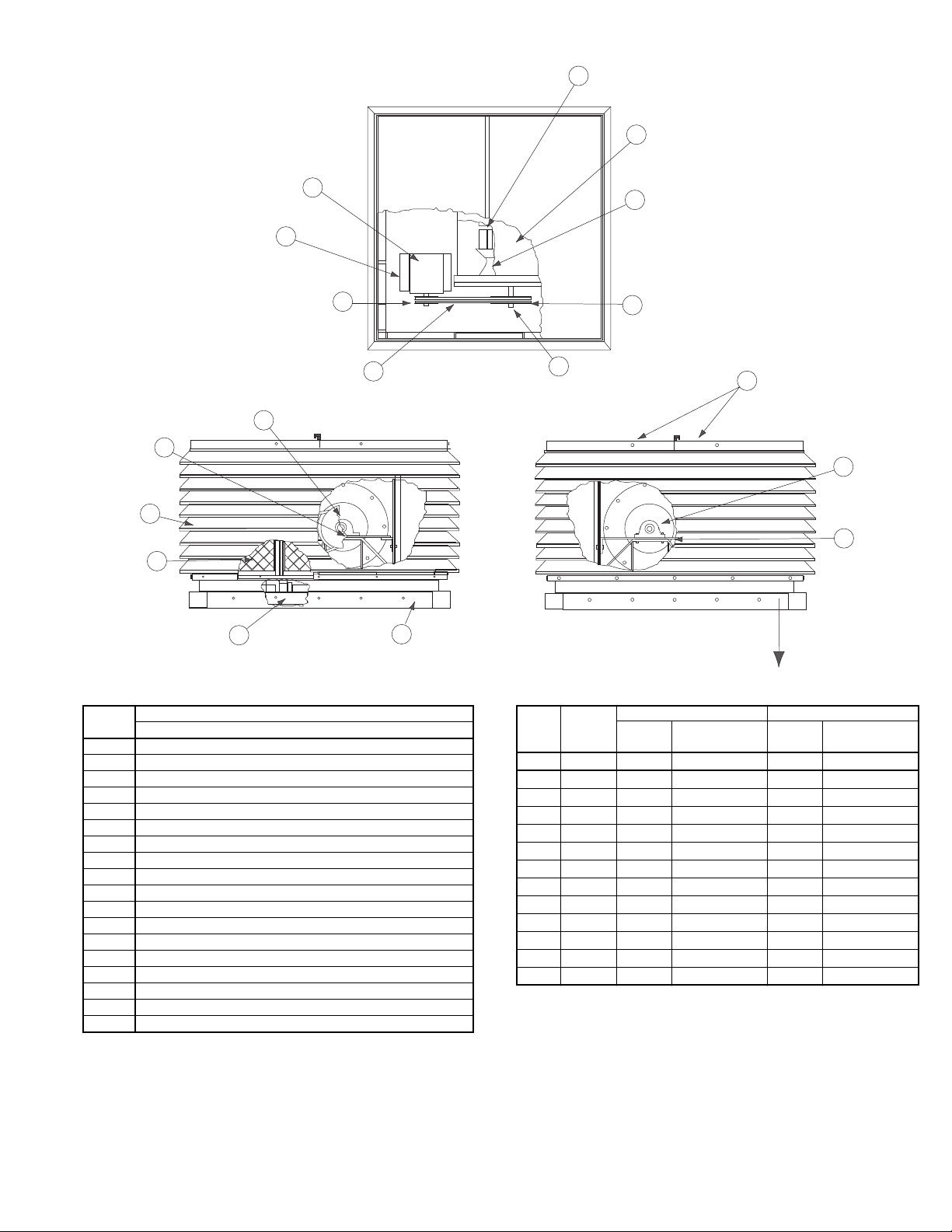
CFS Parts List
5
6
16
15
17
14
3
18
Drive Side View
4
2
1
To p V i e w
13
9
7
8
10
11
12
Airflow
Free Side View
Part No.
Description
Sizes 120 - 365
1 Belt Set
2 Motor Sheave
3 Motor Slide Base
4 Motor
5 Wheel Assembly
6 Blower Housing
7 Inlet Cone (2)
8 Fan Sheave
9 Fan Shaft
10 Top Cap
11 Free Side Bearing
12 Free Side Bearing Support
13 Curb Cap
14 Base
15 Filter Set
16 Tier Assembly
17 Drive Side Bearing Support
18 Drive Side Bearing
Filter Information
Total
Size
Number
of Filters
120 8 4 20-5/8 x 16-1/8 4 20-5/8 x 16-1/8
135 8 4 23-1/4 x 19-5/8 4 23-1/4 x 19-5/8
150 8 4 24-5/8 x 23-1/8 4 24-5/8 x 23-1/8
165 8 4 26-5/8 x 26-1/8 4 26-5/8 x 26-1/8
180 12 6 30-1/8 x 19 6 30-1/8 x 19
195 12 6 33-5/8 x 20 6 33-5/8 x 20
210 12 6 37-1/8 x 21 6 37-1/8 x 21
225 12 6 40-5/8 x 21-7/8 6 40-5/8 x 21-7/8
245 12 6 40-5/8 x 23-3/4 6 40-5/8 x 23-3/4
270 12 6 51-1/8 x 25-1/2 6 51-1/8 x 25-1/2
300 12 6 54-5/8 x 27-1/4 6 54-5/8 x27-1/4
330 20 12 33-3/8 x 30-7/8 8 40-5/8 x 30-7/8
365 20 12 36-1/4 x 32-5/8 8 40-5/8 x 32-5/8
Long Side Short Side
Number
of Filters
Filter Size
Number
of Filters
Filter Size
7
Page 8

Troubleshooting
Problem and Potential Cause
Low Capacity or Pressure
•Incorrect direction of rotation. Make sure the fan rotates in same direction as the arrows on the motor or belt drive assembly.
•Poor fan inlet conditions. There should be a straight clear duct at the inlet.
•Improper wheel alignment.
Excessive Vibration and Noise
•Damaged or unbalanced wheel.
•Belts too loose; worn or oily belts.
•Speed too high.
•Incorrect direction of rotation. Make sure the fan rotates in same direction as the arrows on the motor or belt drive assembly.
•Bearings need lubrication or replacement.
•Fan surge or incorrect outlet conditions.
Overheated Motor
•Motor improperly wired.
•Incorrect direction of rotation. Make sure the fan rotates in same direction as the arrows on the motor or belt drive assembly.
•Cooling air diverted or blocked.
•Improper inlet clearance.
•Incorrect fan RPMs.
•Incorrect voltage.
Overheated Bearings
•Improper bearing lubrication
•Excessive belt tension.
Limited Warranty
Loren Cook Company warrants that your Loren Cook fan was manufactured free of defects in materials and workmanship, to the extent stated herein. For a period of one (1)
year after date of shipment, we will replace any parts found to be defective without charge, except for shipping costs which will be paid by you.
This warranty is granted only to the original purchaser placing the fan in service.
This warranty is void if the fan or any part thereof has been altered or modified from its original design or has been abused, misused, damaged or is in worn condition or if the
fan has been used other than for the uses described in the company manual. This warranty does not cover defects resulting from normal wear and tear.
To make a warranty claim, notify Loren Cook Company, General Offices, 2015 East Dale Street, Springfield, Missouri 65803-4637, explaining in writing, in detail, your complaint
and referring to the specific model and serial numbers of your fan. Upon receipt by Loren Cook Company of your written complaint, you will be notified, within thirty (30) days of
our receipt of your complaint, in writing, as to the manner in which your claim will be handled. If you are entitled to warranty relief, a warranty adjustment will be completed within
sixty (60) business days of the receipt of your written complaint by Loren Cook Company.
This warranty gives only the original purchaser placing the fan in service specifically the right. You may have other legal rights which vary from state to state.
For fans provided with motors, the motor manufacturer warrants motors for a designated period stated in the manufacturer’s warranty. Warranty periods vary from manufacturer
to manufacturer. Should motors furnished by Loren Cook Company prove defective during the designated period, they should be returned to the nearest authorized motor service station. Loren Cook Company will not be responsible for any removal or installation costs.
Corporate Offices: 2015 E. Dale Street Springfield, MO 65803 417.869.6474
lorencook.com
8
CFS IOM Dec 2013
 Loading...