

Page 1
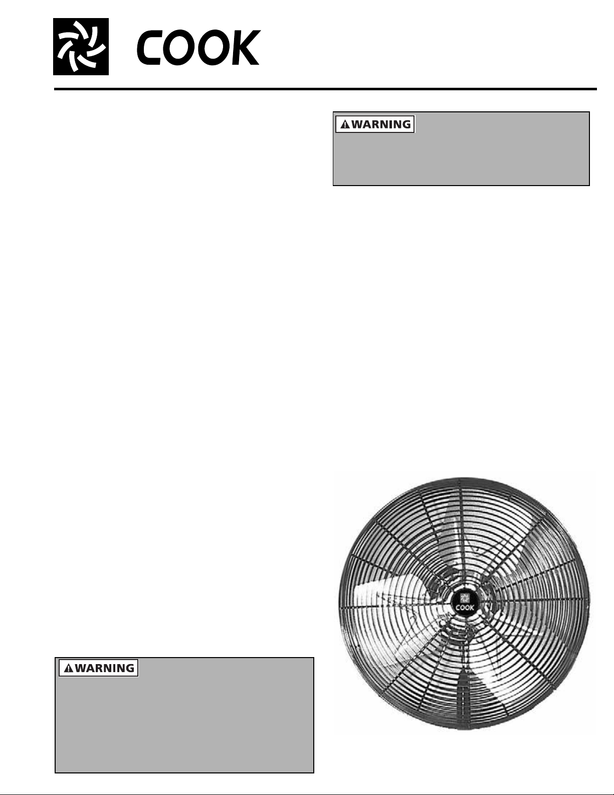
CAC
Air Circulators
INSTALLATION, OPERATION, AND MAINTENANCE MANUAL
This publication contains the installation, operation
and maintenance procedures for standard units of the
CAC - Air Circulator Fans.
• CAC-DF • CAC-WH • CAC-M • CAC-CH • CAC-FH
• CAC-MH • CAC-WX • CAC-WW • CAC-WO • CAC-PO
Carefully read this publication prior to any installation
or maintenance procedure.
Loren Cook catalog, CAC, provides additional information
describing the equipment, fan performance, available accessories and specification data.
For additional safety information, refer to AMCA publication 410-96, Safety Practices for Users and Installers of
Industrial and Commercial Fans.
All of the publications listed above can be obtained from
Loren Cook Company by phoning (417)869-6474, extension
166; by FAX at (417)832-9431; or by e-mail at info@lorencook.com.
For information and instructions on special equipment,
contact Loren Cook Company at (417)869-6474.
Receiving and Inspection
Carefully inspect the fan and accessories for any damage
and shortage immediately upon receipt of the fan.
• Insepect for any damage that may have occurred during
transit.
• Shipping damage claim must be filed with carrier.
• Check all bolts, screws, setscrews, etc. for looseness
that may have occurred during transit. Retighten as
required.
• Record on the Delivery Receipt any visible sign of dam-
age.
Handling
Lift and support Air Circulator fans as per the assembly
instructions (See Page 2). Do not use hooks, clamps, or
forks to lift any of the circulator heads. Do not lift oscillating
head by their connecting arm or gear assembly.
Storage
To maintain good working condition of the fan do not store
outdoors, follow the additional instructions below.
• Periodically rotate the propeller to keep a coating of
grease on all internal bearing parts.
• Periodically inspect the fan to prevent damaging conditions.
• Cover the unit with some type of weather cover to prevent
moisture, corrosion, dirt or dust accumulation.
General Safety Information
To reduce the risk of fire, electric shock, and injury to persons, circulator must be installed with brackets that are
marked on their cartons to indicate the suitability with
model. Other brackets cannot be substituted.
To reduce the risk of fire, electric shock, or injury to
persons, observe the following:
a. Use this unit only in the manner intended by the
manufacturer. If you have questions, contact the
manufacturer.
b. Before servicing or cleaning unit, switch power OFF at
service panel and lock service disconnecting means to
prevent power from being switched on accidentally.
When the service disconnecting means cannot be
locked, securely fasten a prominent warning device,
such as a tag, to the service panel. This is important
with motors equipped with automatic reset thermal
protection. Motor may activate without warning.
c. Installation work and electrical wiring must be done by a
qualified person(s) in accordance with all applicable
codes and standards, including fire-rated construction.
d. When cutting or drilling into wall or ceiling, do not
damage electrical wiring and other hidden utilities.
This unit has rotating parts. Safety precautions should be
exercised at all times during installation, operation, and
maintenance. ALWAYS disconnect power prior to
working on fan. Disconnect switches are recommended.
Place the disconnect switch near the fan in order that the
power can be swiftly cut off in case of an emergency, and
in order that maintenance personnel are provided
complete control of the power source.
CAC-P
Page 2
Motors may be equipped with automatic reset thermal
protection. Motor may activate without warning.
Do not place body parts or objects in circulator, motor
openings, or drives while motor is connected to the
power source.
To reduce the risk of fire, electric shock, or injury to
persons, observe the following: Do not use a three-prong
to two-prong adapter on the power cord. Do not use
circulators with a solid state speed control device. Do not
depend on any switch or thermostat to disconnect power
supply. Always unplug the power cord.
1. Read and follow all instructions, cautionary markings
and make sure power source conforms to requirements
of equipment.
2. Follow all local electrical and safety codes, as well as
the National Electrical Code (NEC) and the
Occupational Safety and Health Act (OSHA) in the United States, including fire rated construction. Ground
motor in accordance with NEC Article 250, (grounding).
3. Avoid extension cords. If used, assure it is UL rated and
of proper type, gauge, and length. Never operate more
than one fan from a single extension cord.
4. Do not kink power cord or allow it to contact oil, grease,
hot surfaces, sharp objects, or chemicals. Replace worn
or damaged cord immediately.
5. Do NOT use general purpose circulators in flammable,
explosive, chemical-laden, or wet or rainy atmospheres.
Use special purpose circulators designed for that
application. Do not attach ductwork to a circulator.
6. In critical applications, use a suitable alarm (air switch,
temperature sensor, etc.) should the circulator
malfunction.
Installation
Installation, troubleshooting, and parts repair to be performed only by qualified personnel.
Where power cord is not provided, connect power to the
motor in accordance with the United States NEC and all
local codes. Motor terminal connection data is provided on
the motor nameplate or on the motor terminal box cover
plate. Use adequate size wire for all branch and feeder
runs.
a. Dock Door Fan (Model CAC-DF): Refer to Page 6, for
correct positioning of parts.
b. Mobile Air Circulators and High Volume, High Velocity
Industrial Fans (Models CAC-M, CAC-WH & CAC-FH):
Locate the fan in the desired location on a stable, level
surface, or on ceiling for ceiling mounted high volume,
high velocity industrial fans. Connect the power cord or
wire unit per all National and Local
Electrical Codes as required.
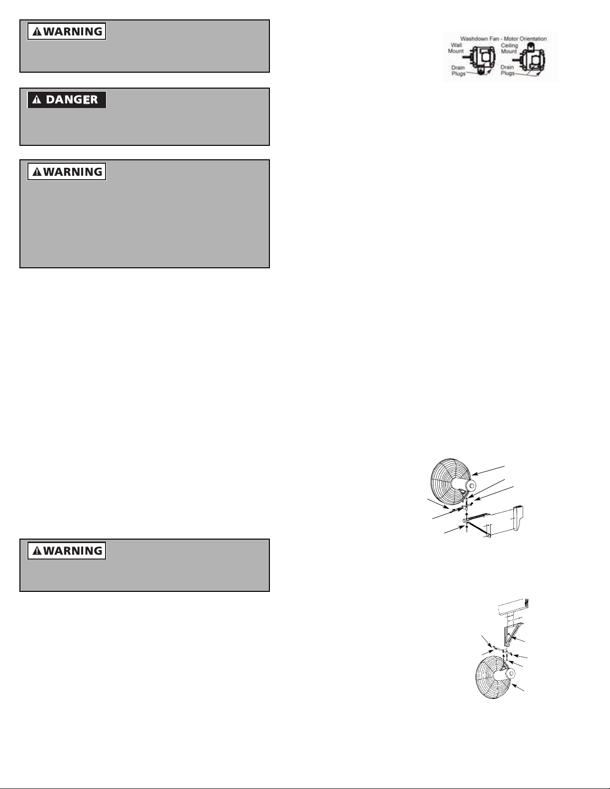
c. Washdown Air Circulators
(CAC-WW): After
mounting motor, remove
drain plugs.
Operation
1. CAC-P, CAC-W, CAC-PO and CAC-WO are operated
by pulling chain: High - Low - Off
2. CAC-M operates by rocker style switch: On - Off
3. CAC-DF operates by two-speed rocker style switch:
Low - Off - High
4. CAC-FH, CAC-WH, CAC-WW and CAC-WX requires
service switch wired by others.
Maintenance
1. Periodically clean propeller, guard, and motor of any
excessive dirt accumulation. Allow unit to cool; motors
can be hot enough to cause injury.
2. Follow motor manufacturer’s instructions for motor
lubrication.
IMPORTANT: When making repairs, use only Loren Cook
authorized repair parts.
Wall/Ceiling Bracket
1. For mounting circulator to wall, post, or ceiling.
Adjustable pivot bracket allows omni-directional air
circulation.
2. Furnished with secondary support cable for use when
circulator is mounted overhead. NOTE: Not
recommended for use with oscillating circulators when
ceiling mounted.
Wall/Ceiling Bracket Assembly Instructions
(Refer to Figures 1 and 2)
1. The wall/ceiling bracket should be assembled with the
swivel bracket as shown in the appropriate illustration.
The bracket has two holes; be sure smaller hole is as
specified in the illustration.
2. Locate the
wall or ceiling
stud nearest
the desired
fan location.
Attach the
bracket to the
stud using (3)
5/16 x 2”lag
screws or
Mounting
Bolts
Swivel Bracket
(Smaller Hole Down)
Mounting Nut
Figure 1 - Wall Mounted Assembly
appropriately sized bolts and nuts if attaching to Ibeams.
NOTE: Always install the
bracket to a minimum of 2 x
4 studding.
3. Position the swivel bracket
in the motor yoke (or along
side the oscillation circular
Swivel Bracket
(Smaller Hole Down)
Mounting
Bolts
cast aluminum support
bracket) and align the pivot
hole with the larger hole in
the swivel bracket.
4. Insert the larger dia. bolt in
Figure 2 - Ceiling
Mounted Assembly
the pivot hole and install
the lock nut finger tight.
5. Insert the smaller dia. bolt in the slot in the motor yoke
2
5-7/16"
10-7/8"
5-7/16"
Circulator
Mounting Bolt
Mounting Nuts
Wall
Stud
10-7/8"
Mounting
Nut
Mounting
Nuts
Mounting
Bolt
Circulator
Page 3
(or support bracket) and smaller hole in the pivot bracket
and install lock nut finger tight.
6. While holding the circulator at the desired angle, tighten
the smaller diameter bolt.
7. Tighten larger bolt to 200-230 in. lbs. and smaller bolt to
150-160 in. lbs., being careful to maintain the desired
position.
8. Plug the power cord into a properly grounded threeprong receptacle.
To avoid personal injury, circulators must be supported
any time angle is adjusted.
Use only as a wall mounting for oscillating units. Do not
use as a ceiling mount.
Pedestal Mount Assembly Instructions
Circulator head comes pre-assembled, ready for installation.
1. Remove the circulator head, base, and column
assembly from the box.
2. Secure the column assembly onto the base using the
four bolts pro-vided. Apply 35-45 in-lbs. of torque.
3. Adjust column to desired height and lock in position by
tightening socket head screw in collar.
IMPORTANT: Do not over-tighten!
4. Place assembled circulator facedown on a flat surface.
5. Tip pedestal assembly over, placing flattened column
end in motor yoke. Align holes and insert larger bolt and
finger-tighten lock nut.
6. Insert smaller bolt through motor adjustment slot and
column end and finger-tighten lock nut.
7. Stand entire unit upright by lifting at the motor end of the
column. Adjust circulator angle to desired position and
tighten larger bolt to 200-230 in. lbs. and smaller bolt
to150-160 in. lbs.
8. Place assembled pedestal and fanon a flat, level
surface. Do not place the cord under the pedestal base.
Locate assembly where cord will not be a tripping
hazard.
9. Insert the plug into a properly grounded three-prong
receptacle. The unit is now ready for operation.
NOTE: Use only the mounting hardware which is provided.
Optional Heavy Duty Floor Pedestal Mountings
(Standard on CAC-PO)
1. Large diameter column adjusts from 3 1/2- 6 ft.
circulator heights.
2. 33” round base is heavy gauge steel for stability and
ease of moving.
Optional Floor Pedestal Assembly Instructions
1. Insert column firmly into tapered cup.
2. Secure column to base by slightly moving the top of the
column by hand while exerting a downward pressure
until column is tight in tapered cup.
3. Insert enclosed screw and washer through the pedestal
base into the pedestal column and tighten to 150in. lbs.
torque securing the assembly.
4. Adjust column to desired height and lock in position by
tightening socket head screw in collar.
IMPORTANT: Do not over tighten!
5. Place assembled circulator face down on a flat surface.
6. Tip pedestal assembly over, placing flattened column
end in motor yoke (or along side cast aluminum support
on oscillating circulators). Align holes and insert larger
bolt and finger tighten lock nut.
7. Insert smaller bolt through motor adjustment slot and
column end and finger tighten lock nut.
8. Stand entire unit upright by lifting at the motor end of the
column. Adjust circulator angle to desired position and
tighten larger bolt to 200-230 in. lbs. and smaller bolt to
150-160 in. lbs.
9. Place assembled pedestal and fan on a flat, level
surface. Do not place the cord under the pedestal base.
Locate assembly where cord will not be a tripping
hazard.
10. Insert the plug into a properly grounded three-prong
receptacle. The unit is now ready for operation.
Optional Open Pedestal Floor Mounting
1. Large diameter column adjusts from 3 1/2- 6 ft. circulator
heights.
2. 38” open base is heavy gauge steel for stability and
designed for ease of area cleaning.
Optional Open Pedestal Assembly Instructions
1. Insert column firmly into base cup.
2. Secure column to base by inserting the enclosed screw
through the base cup hole and tightening to 50-75 in.
lbs.
3. Adjust column to desired height and lock in position by
tightening socket head screw in collar.
NOTE: Refer to Step 5 of the previous section for
assembling the circulator head to the pedestal.
NOTE: Use only the mounting hardware which is
recommended for use on Cook Air Circulators.
Optional Suspension Bracket
1. For mounting circulators from ceiling beams or rafters.
2. Furnished with secondary support cable for use when
circulator is mounted overhead.
Oscillating circulators must not be used with suspension bracket.
Optional I-Beam Mount
1. For mounting circulator from I-beams and columns.
Adjustable bracket allows omni-directional air
circulation.
2. Length can be increased by adding apiece of standard
1-1/2” threaded pipe between the I-beam mount flange
and the yoke adapter.
NOTE: Use only the mounting hardware which is
recommended for use on Cook Air Circulators.
Optional Suspension Bracket
(Refer to Figure 3)
1. The suspension bracket is designed to fit over standard
size 2” lumber and should be hung from any horizontal
member 2 x 3” or larger.
3
Page 4

2. Install a lag screw
through the
mounting hole to
hold the bracket
securely to the
wooden member.
Mounting
Bolts
Beam
Mounting
Nuts
3. Position
suspension
Circulator
bracket in the
motor yoke and
align bolt holes.
4. Insert the larger
Figure 3 - Suspension Bracket
Installation
dia. bolt in the pivot
hole and install the lock nut finger tight.
5. Insert the smaller dia. bolt in the slot in the motor yoke
(or support bracket) and smaller hole in the pivot
bracket and install lock nut finger tight.
6. While holding the circulator at the desired angle, tighten
the smaller dia. bolt.
7. Tighten larger bolt to 200-230 in. lbs. and smaller bolt to
150-160 in. lbs., being careful to maintain desired
position.
8. Plug the power cord into a properly grounded threeprong receptacle.
NOTE: No replacement parts available.
Optional I-Beam Mount Assembly Instructions
(Refer to Figure 4)
1. (Locate the L-shaped
pipe to the desired
location on the I-beam
flange). Install the 5/16 x
2” U-bolts over the pipe
and through the
clamping plate holes.
The flat part of the
clamping plate fits on the
I-beam flange and the
end with the slight bend
goes against the pipe.
Finger tighten the nuts
on the U-bolt.
2. Slide the clamping plate
onto I-beam flange until
Figure 4 - I-Beam Installation
U-bolts contact flange.
3. Tighten nuts on U-bolt so pipe does not move.
4. Screw on the adapter mount as far as it will go to the Lshaped pipe. Rotate adapter mount back to desired
location and tighten set screw in pipe coupling.
5. Install circulator to adapter mount using hardware
provided. Tilt fan to desired angle and tighten larger bolt
to 200-230 in. lbs. and smaller bolt to150-160 in. lbs.
6. Install secondary support cable according to
instructions.
7. Move fan control rocker switch to OFF position and plug
power cord into a properly grounded three-prong
receptacle.
Secondary Support Cable
(For use with CAC-W, CAC-WW and CAC-WX)
To insure proper installation, carefully read and follow
steps 1 thru 6 listed.
Use of this product does not guarantee protection
against injury of persons. Mounting of both the circulator and cable could fall if subject to abuse or neglect or if
improperly installed.
Figures 2 and 3 show typical installations using
suspension and wall/ceiling type brackets.
1. Loop one end of the cable
around the large diameter
wires of both the front and
rear guard.
1 - 2" Tail
Tight Loop
in Cable
(Refer to Figure 5).
2. Attach a cable clamp with
the “U” on the tail side of
the loop leaving a tail of
approximately 1 to 2”.
Tighten clamp nuts to 32
Figure 5 - Cable Clamping
in. pounds and torque
forming a tight loop. Make sure no part of the cable
interferes with the propeller.
3. Attach a second clamp (not shown) 1 to 2” from the first
and tighten to 32 in. pounds torque. A tail of 1 to 2”
must extend past the second clamp.
4. Wrap the other end of
the cable around a
secure building joist,
beam, truss, or other
support near the fan
(Refer to Figures 6 and
7). Take up all excess
slack in the cable. If
the fan is an oscillating
model, leave enough
slack to allow free
Ceiling
Joists
Secondary
Support
Cable
Figure 6 - Suspension Bracket
Support
Bracket
movement through range of motion.
5. Attach the two (2)
remaining cable
clamps as indicated in
step 2. The excess tail
should be trimmed to
extend 1 to 2” past the
second clamp.
6. Check the assembly to
assure the propeller is
free of all obstructions.
Figure 7 - Wall/Ceiling Bracket
Secondary
Support
Cable
Wall/Ceiling
Bracket
NOTE: No replacement
parts available.
Large
Guard
Wires
4
Page 5

Assembly & Installation – (CAC-DF)
IMPORTANT: It is recommended that the wall mount be
assembled and installed prior to mounting fan.
1. Assemble the back
channel, bottom
channel, and arm
assembly with four
bolts (5/16-18 x 2-1/
2" long) and nylon
locknuts (Refer to
Figure 8).
2. Tighten all bolts.
IMPORTANT: Do not
Figure 8 - Mounting Arm
Assembly
over tighten bolts.
Overtightening will cause the channels to collapse.
Mounting Fan/Arm Assemblies
Anchoring hardware and building structure must be
capable of holding 500 pounds per bolt.
1. Layout a rectangular pattern for four (4) bolt anchors
that is 5.0” wide to bolt centers at top and bottom
and10.0” high at both sides of bolt centers.
2. Mount the bracket to
the wall as shown in
Figure 9.
3. Locate two 1/2 x 11/2”
long bolts, two 1/2”
nuts, three 1/2” flat
washers and one
friction washer. These
will be used in step 4
to install the arm
assembly.
4. Insert the arm assembly
into the wall bracket as
shown in Figure 10.
NOTE: Friction washer
goes between the wall
bracket and lower pivot
channel.
5. (Refer to Figure 11)
Insert the steel spacer
tube in the end of the
arm tube as shown.
Line up holes in tube with inside of spacer.
6. Insert the 3/8 x 3” long
carriage bolt through
the hole in the top
center portion of the
fan yoke.
7. Slip one (1) flat washer
onto bolt followed by
the bent “Z” bracket
(silver color).
NOTE: Position the
upward extending leg
toward the front of the fan as shown in Figure 11. Add
another (1) flat washer on top of “Z” bracket.
Figure 9 - Mounting Bracket
Orientation
Figure 10 - Arm Installation
Black "Z"
Bracket
Steel
Spacer Tube
Silver "Z"
Bracket
Carriage
Bolt
Figure 11 - Fan and Light
Attachment
IMPORTANT: Do not assemble without “Z” brackets. The
“Z” brackets are designed to prevent damage to the
cords caused by twisting, which may occur if the
brackets are not present.
8. Attach the fan to wall mount by inserting the carriage
bolt in the hole provided at the end of the square tube.
Add black colored “Z” bracket with leg toward the front
of the light extending downward. Add light. Slip one (1)
flat washer over top, followed by the 3/8-16nylon
locking nut provided.
9. Tighten nut to a snug fit. The pivot should provide
sufficient resistance to hold position while in operation,
but still allow movement for easy positioning.
10. Plug fan and light in as shown. Route the fan cord in a
loop as shown to prevent pinching.
NOTE: The recommended location for the electrical outlet is
directly below the wall mount pivot.
Lamp Installation
1. Screw lamp (300 watt max.) into socket until seated
firmly.
2. For lamp replacement, press spring loaded, black push
button in the back of the shade. This will relieve the
spring tension on the socket and allow for easy removal
of the lamp.
Do not use ordinary A-type light bulbs, or any lamp rated
higher than 300 watts.
CAC-MH Assembly
1. Tilt fan onto its side.
2. Using 2” bolts and nuts, bolt tube to angle, taking care to
align proper holes (See CAC-MH Parts List on Page 8).
Tighten bolts finger-tight. (All hardware will be tightened
fully in step 5).
3. Bolt gussets (See CAC-MH Parts List on Page 8) to
tube/angle assembly, finger-tight.
4. Bolt tube/angle assemblies to sides. Position adjustable
stand against fan stand, matching holes in fan stand to
slots in adjustable stand. Bolt together with 1” bolts and
nuts.
5. Tighten all bolts securely.
6. Assemble casters as shown.
7. Chock wheels. Carefully tilt unit upright.
CAC-WH Assembly Column Installation
1. Locate column for mounting bracket. (NOTE: 6”
minimum, 10” maximum column width).
2. Mount the Column Mounting Bracket to the column
using four 5/8” bolts, grade 5 minimum (not included),
through the Back Plate (See CAC-WH Parts List on
Page 7). NOTE: Bolt length will be determined by the
width of the column. Bolts should be approximately 2”
longer than column depth.
3. Ensure that the centerline of the bracket and the
centerline of the column align with each other and that
the bolts are placed against the column’s surface before
tightening.
5
Page 6

Troubleshooting Chart
Symptom Possible Cause(s) Corrective Action
Fan inoperative
Fan cycles on and off
Unit fails to
oscillate (sweep)
Excessive noise
while operating
Insufficient air flow
1. Blown fuse or open circuit breaker
2. Defective motor or
switch
3. Broken belt
1. Thermal protector
2. Faulty wiring or control
switch
1. Connection arm not
secured
2. Defective gear assembly
1. Defective bearing
2. Loose or damaged propeller
3. Loose, worn, or dirty belt
4. Motor not secure
1. Belt slippage
2. Guard excessively dirty
1. Replace or reset
2. Repair or replace
3. Replace
1. Check for obstructions
to air flow , voltage,
intake air temperature
2. Repair or replace
1. Tighten
2. Replace
1. Replace shaft/bearing
assembly
2. Tighten or replace
3. Adjust, replace, or
clean
4. Tighten motor nuts
1. Replace and/or adjust
tension
2. Clean guards
4. Torque bolt to 85-90 ft-lb.
5. Proceed to unit mounting.
Wall Mounting
1. Locate a solid support structure within the wall.
2. Discard the back plate when wall mounting.
3. Use four 5/8” x 2” lag bolts, grade 5 minimum (not
included), to secure bracket to the wall.
4. Proceed to unit mounting.
Unit Mounting
1. Using 4-1/2” x 1/75” bolts and nuts, attach the high
volume, high velocity industrial circulator to the column/
wall bracket (See CAC-WH Parts List on Page 7).
Tighten the nuts and bolts to 45-50 ft-lb torque.
2. Using the safety cable holes located in the Column
Mounting Bracket and the Back Plate, install the safety
cable (See CAC-WH Parts List). Overlap the cable’s
ends, and tighten the clamps and nuts to 45 ft-lb torque.
The cable should not exceed 1” of slack.
CAC-W / CAC-WO Parts List
3
2
4
1
Part
No.
Description
1 Propeller
2 Front Guard
3 Rear Guard
7
4 Motor Assembly (includes cord & switch)
7 Wall/Ceilling Bracket
CAC-P / CAC-PO Parts List
3
2
1
4
17
CAC-M Parts List
15
15
16
9
8
6
17
1
10
3
6
2
4
12
11
5
14
Part
No.
Description
1 Propeller
2 Front Guard
3 Rear Guard
6
4 Motor Assembly (includes cord & switch)
5 Pedestal Base Assembly
6 Column Assembly
5
Part
No.
Description
1 Housing
2 Motor (w/key)
3 Propeller
4 SPST Switch
5 Cord Assembly
16
13
6 Guard
7 Handle
81/2” Dia. Axle
9 7” Dia. Wheel
7
10 #10-32 Lock Nut
11 Strain Relief
12 1/4-20 x 1/2” HWH Screw
13 Wire Tie
14 1” Crutch Tip
15 Parts Pack
16 1/4-20 x 1/2” Screw
17 1/4-20 Nut
6
Page 7

CAC-WW / CAC-WX Parts List
5
4
2
3
CAC-CH Parts List
14
2
4
Hazardous
Location Mount
4
6A
Part
No.
Description
1 Motor*
2 Propeller
3 Guard Set: Front Guard & Rear Guard
4
1
4 Mounting Hardware Package
5 1/4”-20 x 1” HHC Screw
6A Wall Bracket
7
4
6B
Washdown Mount
6B Wall/Ceiling Bracket (Includes support cable)
7 5/16” x .688” x .065” Flat Washer
*Does not include cord and switch.
Part
No.
Description
1 Propeller
2Guard
3 1/2”-13 x 1.5” Hex Bolt
4 3/8”-24 Nut
3
5 3/8”-24 x 1” Bolt
6 3/8” x 13/16” Washer
7 5/16”-24 x .75” HHC Bolt
12
8
10
11
9
7
1
2
6
5
8 5/16”-24 Nut
9 5/16” x .688” Washer
10 .88” Conduit Bushing
11 Motor *
12 Housing Assembly
13 Split Taper Bushing
14 Bracket Assembly
*Replacement motor does not include cord.
CAC-WH Parts List
Column
1
2
3
7
10
(CAC-CH with wall mount assembly)
13
8
9
4
Part
No.
Description
1 Column Mounting Bracket
2 1/2 “ x 1.75” Flanged Bolt
31/2” Nut
5
6
4 Back Plate
5 Safety Cable
6 Cable Clamp with Nuts
7 5/8” Bolt (Grade 5 min.)
85/8” Nut
9 5/8” Washer
(1.25” OD min. x 0.12” thickness min.)
10 5/8” Split Lock Washer
7
Page 8

8
CAC-FH Parts List
12
3
Part
2
No.
1 Propeller
Description
2 Guard
12
8
10
11
1
2
3 1/2”-13 x 1.5” Hex Bolt
4 3/8”-24 Nut
5 3/8”-24 x 1” Bolt
6 3/8” x 13/16” Washer
7 5/16”-24 x .75” HHC Bolt
8 5/16”-24 Nut
9 5/16” x .688” Washer
10 .88” Conduit Bushing
4
9
7
13
6
5
11 Motor *
12 Housing Assembly / Stand Assembly
13 Split Taper Bushing
*Replacement motor does not include cord.
CAC-MH Parts List
2
8
1
8
6
12
10
11
7
8
9
4
(CAC-FH with stand assembly)
Part
10
11
No.
1 Left Gusset
Description
2 Right Gusset
12
3 Tubing Assembly
4 Angle Assembly
5 Right Side Channel Assembly
7
3
5
6 Left Side Channel Assembly
7 3/8 - 16 x 1.00” Bolt
8 3/8 - 16 x 2.00” Flanged Bolt
9 3/8 - 16 Flanged Nut
10 Cotter Pin
11 5” Dia. Wheel
12 1/2 x 1.4 x .11 Zinc Washer
Limited Warranty
Loren Cook Company warrants that your Loren Cook fan was manufactured free of defects in materials and workmanship, to the extent stated herein. For a period of one (1)
year after date of shipment, we will replace any parts found to be defective without charge, except for shipping costs which will be paid by you. This warranty is granted only to
the original purchaser placing the fan in service. This warranty is void if the fan or any part thereof has been altered or modified from its original design or has been abused,
misused, damaged or is in worn condition or if the fan has been used other than for the uses described in the company manual. This warranty does not cover defects resulting
from normal wear and tear. To make a warranty claim, notify Loren Cook Company, General Offices, 2015 East Dale Street, Springfield, Missouri 65803-4637, explaining in
writing, in detail, your complaint and referring to the specific model and serial numbers of your fan. Upon receipt by Loren Cook Company of your written complaint, you will be
notified, within thirty (30) days of our receipt of your complaint, in writing, as to the manner in which your claim will be handled. If you are entitled to warranty relief, a warranty
adjustment will be completed within sixty (60) business days of the receipt of your written complaint by Loren Cook Company. This warranty gives only the original purchaser
placing the fan in service specifically the right. You may have other legal rights which vary from state to state.
Corporate Offices: 2015 E. Dale Street Springfield, MO 65803 417.869.6474
lorencook.com
8
CAC IOM - July 2004
 Loading...