

Page 1
Automatic Belt Tensioner Supplement II
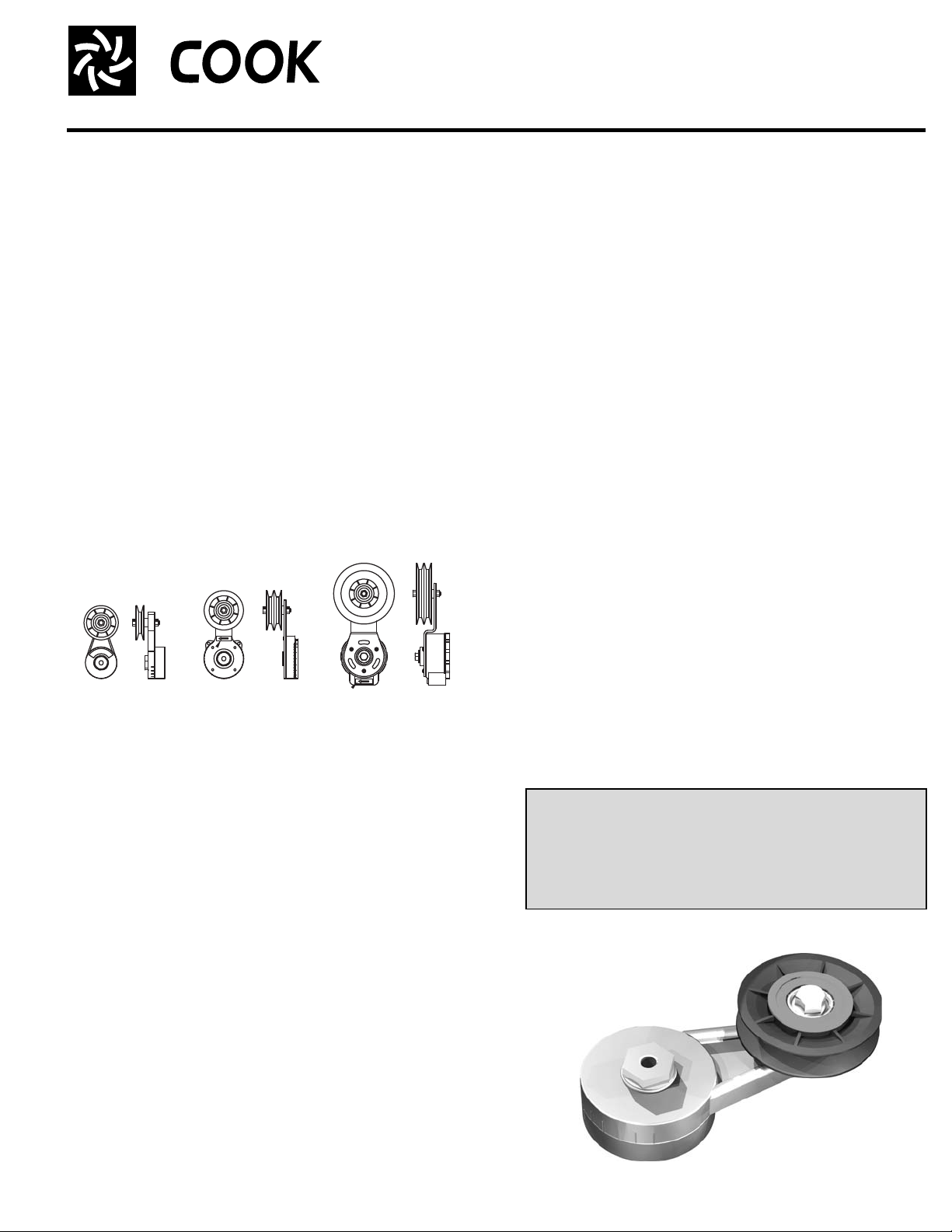
BELT TENSIONER IDENTIFICATION DETAIL
BI-DIRECTIONAL
TENSIONER
DIRECTIONAL ARROW
(SEE RT3000/RT4000
INSTALLATION NOTES)
DIRECTIONAL ARROW
(SEE RT3000/RT4000
INSTALLATION NOTES)
RT1000 WITH
1 GROOVE “A”
RT3000 WITH
2 GROOVE “A”
RT4000 WITH
2 GROOVE “B”
AWB, EWB, XLWH, XMWH, APB, EPB, XLPH, XLWH, H-Series, ETE, ETS,
LXU, LEU, and LTU Units - Sizes 20 to 72
INSTALLATION, OPERATION, AND MAINTENANCE MANUAL
This publication contains the installation, operation
and maintenance instructions for the Automatic Belt
Tensioner.
Carefully read this publication prior to any insta llation
or maintenance procedure.
Loren Cook brochure, Automatic Belt Tensioner, provides
additional information describing the equipment, fan performance, available accessories, and specification data.
For additional safety information, refer to AMCA publication 410-96, Safety Practices for Users and Installers of
Industrial and Commercial Fans.
All of the publications listed above can be obtained from
Loren Cook Company by phoning (417)869- 6474, extension
166; by FAX at (417)832-9431; or by e-mail at info@lorencook.com.
For information and instructions on special equipment,
contact Loren Cook Company at (417)869-6474. The Automatic Belt Tensioner uses sealed bearings which do not
require maintenance and contains no user-serviceable
parts. Do not disassemble the belt tensioner.
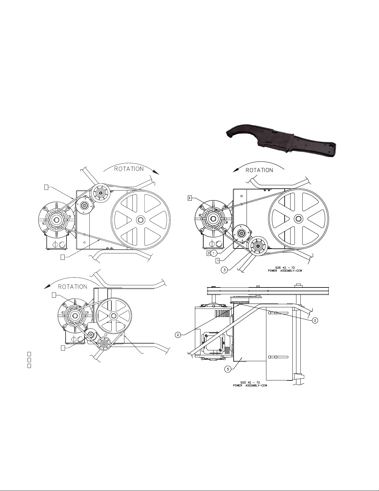
Belt Tensioner Mounting Instructions
Belt T ensioner Alignment and Tensioning Instructions for
Clockwise Units:
1. Tighten the bolt finger tight allowing tensioner assembly to
rotate freely.
2. Align driver and driven sheaves with tensioner idler pulley.
3. Install belt around all sheaves and rotate tensioner counterclockwise (clockwise for counter clockwise units) until
belt feels tight and you feel light spring tension.
4. While holding tensioner at this position, use a marking
pencil to make an alignment mark on the tensioner and
the outboard bearing support so that the tensioner can be
rotated back to the mark after removing the belt.
5. Remove the belt and realign the marks on the tensioner.
Now rotate the belt tensioner assembly counterclockwise
(clockwise for counter clockwise units) until the alignment
marks are spaced approximately 1/2” to 3/4” apart.
6. Tighten mounting bolt fully and install belt by wrapping it
around tensioner idler pulley. Use palm of hand and rotate
tensioner arm clockwise (counterclockwise for counter
clockwise units) until there is enough slack in the belt to
allow it to slip over the driver pulley and then the driven
pulley. If using RT4000 tensioner and spring force is to
much to rotate tensioner arm enough to install belts by
hand, use procedure given in Notes 2 & 3.
7. Check belt tension by pushing on the belt on the tension
side. Note that the tensioner will move in as more force is
applied by pushing on the belt. Hold the end of the belt
tensioner arm stationary with firm hand pressure and push
on the belt again. If the tension feels right and the tensioner arm doesn’t move with an equal amount of force
applied, then the tension should be correct. If there is any
doubt that the tension is correct, check it by starting the
fan and listening for belt squeal. If excessive belt squeal is
heard - loosen tensioner mounting bolt, and rotate ten-
Unit Sizes 20 - 36:
1. Fasten mounting bracket to outside surface of bearing
support plate using 2 wizz bolts and nuts through the
upper slot as shown. Adjust bracket to lowest point and
tighten mounting bolts fully.
2. Set belt tensioner assembly on top surface of the
bracket and line up with hole. Bring a 3/8-16 x 1-1/4 b olt
through the hole and thread it into the bottom of the tensioner.
Unit Sizes 42 - 72:
1. Fasten belt tensioner motor plate to the bearing support
plate using 8 wizz bolts and nuts as shown.
2. Set belt tensioner assembly on the top flange of the
motor plate and line up with inside hole (use outside
hole for 20” sheaves and larger). Bring a 3/8-16 x 1-1/4
bolt (7/16-14 for RT4000) through the hole and thread it
into the bottom of the tensioner.
Caution:
Do not use the top assembly nut to add additional ten-
sion as this may potentially cause damge the tensioner. It must be re-positioned per tensioning
assembly instructions.
Automatic Belt Tensioner
Page 2
sioner counterclockwise an additional 1/2”, and repeat
steps 6 and 7.
RT3000/RT4000 Installation Notes:
1.The tensioner comes with a limited-use spanner
wrench. The spanner wrench must be used to hold the
tensioner base when loosening the mounting bolt.
2. The RT3000 and RT4000 have a directional arrow to
ensure proper installation. The arrow must always point
toward the belt being tensioned. In this application,
units with counterclockwise rotation point clockwise and
clockwise rotation point counter clockwise. If arrow is
pointing the wrong direction, remove the back of tensioner housing and the spring. Then flip the sprin g over,
the spring’s center “tail” must engage the slot in the
center shaft. Then push out the d irectional arrow piec e
located in the arm assembly, a nd reverse the arro w so
it points the opposite way and snap in place. Note that if
the arrow piece is not pointing in the correct direction,
1
the tensioner cannot be reassembled.
The RT4000 tensioner requires considerable force to
overcome it’s spring tension. If force is so strong that
the procedure given in Note 6 wo n’t work, use the following procedure. With tensioner mounting bolt only
finger tight, rotate tensioner back so that belts can be
installed easily. Now rotate tensioner arm until belts
begin to tighten and you feel light spring tension. Hook
in provided spanner wrench and rotate tensioner arm
until alignment marks are 3/4 apart. While holding
spanner wrench securely at this position, tighten tensioner mounting bolt fully and remove spanner wrench.
3.Once installed, the RT4000 tensioner has considerable
force.
2
2
NOTES:
SLACK SIDE OF BELT
1
2
TENSION SIDE OF BELT
IF NECESSARY, ADJUST HEIGHT
3
OF TENSIONER WITH SHIMS
Limited Warranty
Loren Cook Company warrants that your Loren Cook fan was manufactured free of defects in materials and workmanship, to the extent stated herein. For a period of one (1)
year after date of shipment, we will replace any parts found to be defective without charge, except for shipping costs which will be paid by you. This warranty is granted only to
the original purchaser placing the fan in service. This warranty is void if the fan or any part the reof has been altered or modifi ed fro m its origin al design or has been abused, misused, damaged or is in worn condition or if the fan has been u sed other tha n f or the u ses descr ibed in t he compa ny manual. Th is warran ty doe s not co ve r defect s result ing from
normal wear and tear. To make a warranty claim, notify Loren Cook Company, General Offices, 2015 East Dale Street, Springfield, Missouri 65803-4637, explaining in writing,
in detail, your complaint and referring to the specific model and serial numbers of your fa n. Upon receipt by Loren Cook Company of your written complaint, you will be notified,
within thirty (30) days of our receipt of your complaint, in writing, as to the manner in which your claim will be handled. If you are entitled to warranty relief, a warra nty adjustme nt
will be completed within sixty (60) business days of the receipt of your written complaint by Loren Cook Company. Thi s warran ty gives only the ori ginal purcha ser placi ng the fan
in service specifically the right. You may have other legal rights which vary from state to state .
1
Size 42 - 72
Power Assembly-CW
Size 20 - 36
Power Assembly
MOUNTING
BRACKET
LOREN COOK COMPANY
Corporate Offices: 2015 E. Dale Street Springfield, MO 65803 417.869.6474
lorencook.com
2
Automatic Belt Tensioner Supplement II - March 2010
 Loading...