

Convoy Security WT105 Installation And Maintenance Instructions Manual
WT105Manual Page 1 of 2 ©2009 Convoy Security
INSTALLATION AND MAINTENANCE INSTRUCTIONS
WT105
Conventional Heat Detector
SPECIFICATIONS
Height: 2.2˝ (55 mm) installed in Base
Diameter: 4.0˝ (103 mm)
Weight: 5.5 oz. (155 g)
Installation Temperatures: –4°F to 150°F (–20°C to 66°C)
Operating Humidity Range: 10% to 93% Relative Humidity Non-condensing
Operating Voltage Range: 9 to 28VDC Volts Non-polarized
Standby Current: 40µA @ 24 VDC
Maximum Alarm Current (LED on: ) ≤30mA @ 24 VDC
Fixed Temperature Rating: 135°F (57°C)
Rate of Rise Detection: Responds to greater than 15°F/min
INSTALLATION
BEFORE INSTALLING
This detector must be installed in compliance with the
control panel installation manual and meet the
requirements of the authority having jurisdiction. In
addition, the National Fire Protection Association has
published codes, standards, and recommended
practices for the installation and use of detectors,
NFPA 72.
Therefore, the installer must be familiar with these
requirements, with local codes, and any special
requirements of the authority having jurisdiction..
NOTICE: This manual should be left with the
owner/user of this equipment.
IMPORTANT: The detector must be tested and
maintained regularly following NFPA 72 requirements.
The detector should be cleaned at least once a year.
GENERAL DESCRIPTION
Model WT105 is intelligent sensors that utilize a
state-of-the-art thermistor sensing circuit for fast
response. These sensors are designed to provide open
area protection with 50 foot spacing capability. Model
WT105 is a rate-of-rise temperature sensor with 135°F
fixed temperature alarm.
Model WT105 is a rate-of-rise with fixed temperature
alarm thermal detector utilizing a state-of-the-art dual
thermistor sensing circuit. These detectors are
designed to provide open area protection with 50-foot
spacing capability, and are to be used with compatible
control panels only.
Two LEDs on each detector light to provide 360°
visibility of the detector indication.
INSTALLATION
NOTE: All wiring must conform to applicable local
codes, ordinances, and regulations.
NOTE: Verify that all detector bases are installed, that
the initiating-device circuits have been tested, and that the
wiring is correct.
Remove power from initiating-device circuits before
installing detectors.
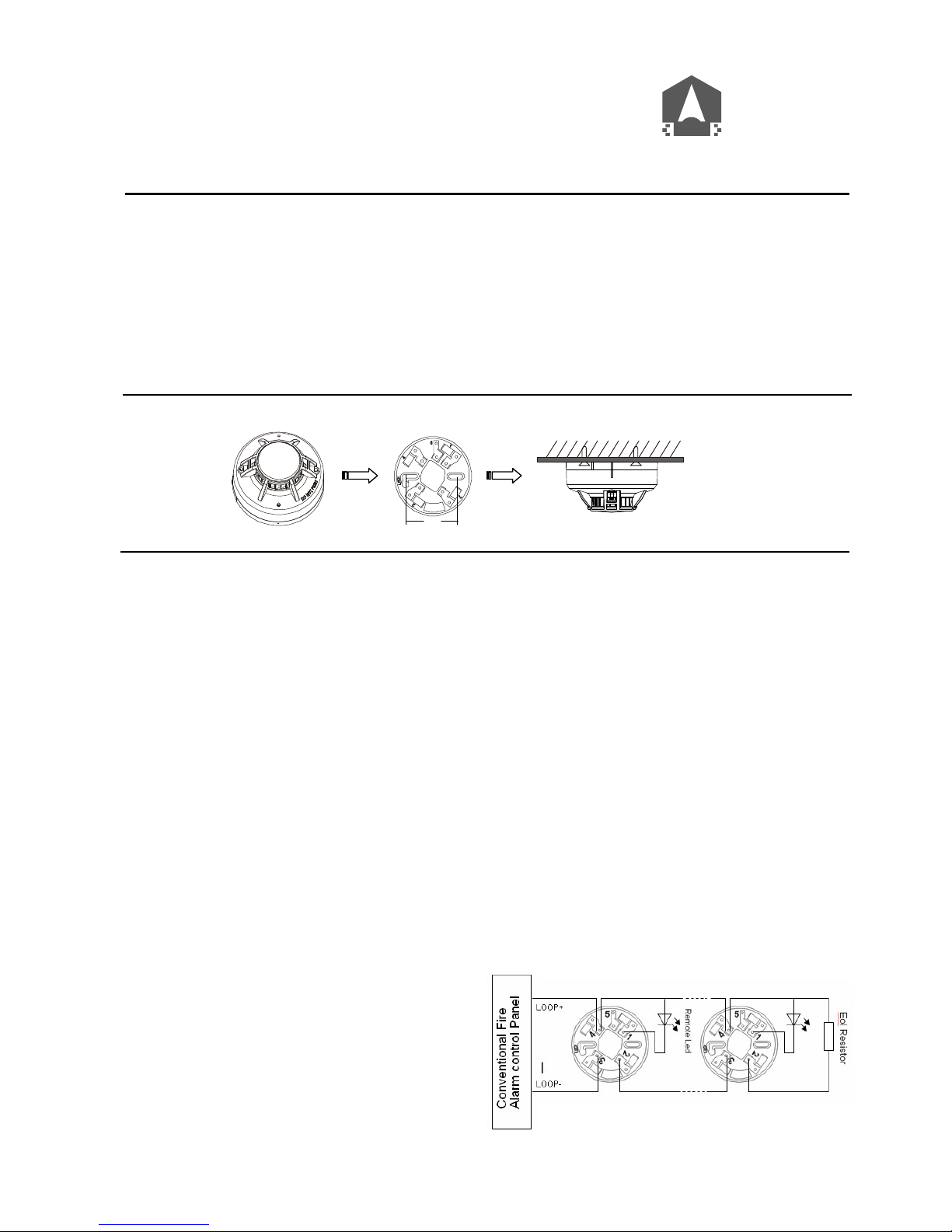
1. Wire the sensor base per the wiring diagram, Figure 1.
2. Install the sensor into the sensor base. Push the sensor
into the base while turning it clockwise to secure it in
place.
3. After all sensors have been installed, apply power to
the control unit.
4. Test the sensor(s) as described in the TESTING section
of this manual.
5. Notify the proper authorities that the system is in
operation.
Figure 1. Wiring diagram:
CONVOY
SECURITY
©
60mmm

WT105Manual Page 2 of 2 ©2009 Convoy Security
Dust covers provide limited protection against
airborne dust particles during shipping. Dust
covers must be removed before the sensors can
sense temperature.
TAMPER-RESISTANCE
Models WT105 include a tamper-resistant capability
that prevents their removal from the bracket without
the use of a tool.
TESTING
Before testing, notify the proper authorities that the
system is undergoing maintenance, and will
temporarily be out of service. Disable the system to
prevent unwanted alarms.
All sensors must be tested after installation and
periodically thereafter. Testing methods must satisfy
the Authority Having Jurisdiction (AHJ). Sensors
offer maximum performance when tested and
maintained in compliance with NFPA 72.
The sensor can be tested in the following ways:
Direct Heat Method (Hair dryer of 1000 – 1500 watts)
1. From the side of the detector, direct the heat toward the
sensor. Hold the heat source about 6 inches (15cm) away
to prevent damage to the cover during testing.
2. The LEDs on the detector should light when the
temperature at the detector reaches the alarm set point. If
the LEDs fail to light, check the power to the detector and
the wiring in the detector base.
3. Reset the detector at the system control panel.
Detectors that fail these tests should be cleaned as
described under MAINTENANCE and retested. If the
detectors still fail these tests they should be returned for
repair.
MAINTENANCE
NOTE: Before cleaning notify the proper authorities that
the system is undergoing maintenance, and therefore the
system will temporarily be out of service. Disable the
loop or system undergoing maintenance to prevent
unwanted alarms.
It is recommended that the sensor be removed from its
mounting base for easier cleaning and that sensors be
cleaned at least once a year. Use a vacuum cleaner to
remove dust from the sensing chamber.
THREE-YEAR LIMITED WARRANTY
Convoy Security warrants its enclosed smoke detector to be free from defects in materials and workmanship under normal use and service for a period of three years
from date of manufacture. Convoy Security makes no other express warranty for this smoke detector. No agent, representative, dealer, or employee of the Company has
the authority to increase or alter the obligations or limitations of this Warranty. The Company’s obligation of this Warranty shall be limited to the repair or replacement of
any part of the smoke detector which is found to be defective in materials or workmanship under normal use and service during the three year period commencing with
the date of manufacture. After phoning Convoy Security’s technical support number for a Return Authorization number, send defective units postage prepaid to Convoy
Security local representative office. Please include a note describing the malfunction and suspected cause of failure. The Company shall not be obligated to repair or
replace units which are found to be defective because of damage, unreasonable use, modifications, or alterations occurring after the date of manufacture. In no case shall
the Company be liable for any consequential or incidental damages for breach of this or any other Warranty, expressed or implied whatsoever, even if the loss or damage
is caused by the Company’s negligence or fault. Some states do not allow the exclusion or limitation of incidental or consequential damages, so the above limitation or
exclusion may not apply to you. This Warranty gives you specific legal rights, and you may also have other rights which vary from state to state.
FCC STATEMENT
This device complies with part 15 of the FCC Rules. Operation is subject to the following two conditions: (1) This device may not cause harmful interference, and (2)
this device must accept any interference received, including interference that may cause undesired operation.
NOTE: This equipment has been tested and found to comply with the limits for a Class B digital device, pursuant to Part 15 of the FCC Rules. These limits are designed
to provide reasonable protection against harmful interference in a residential installation. This equipment generates, uses and can radiate radio frequency energy and,
if not installed and used in accordance with the instructions, may cause harmful interference to radio communications. However, there is no guarantee that interference
will not occur in a particular installation. If this equipment does cause Harmful interference to radio or television reception, which can be determined by turning the
equipment off and on, the user is encouraged to try to correct the interference by one or more of the following measures:
– Reorient or relocate the receiving antenna.
– Increase the separation between the equipment and receiver.
– Connect the equipment into an outlet on a circuit different from that to which the receiver is connected.
Please refer to insert for the Limitations of Fire Alarm Systems
CAUTION
 Loading...