


Convision V600 A Series
User Manual
Version 5.1
November 2003
© Convision Systems GmbH
All rights reserved
No part of this manual may be reproduced or transmitted in any form without the prior
written permission of Convision Systems GmbH.
All the information and descriptions have been compiled with great care on the basis
of thorough research. Despite our great care, we cannot completely rule out errors or
altered applications that may lead to changed operational sequences or different
results. Convision Systems GmbH can accept neither legal responsibility nor any
other liability for any consequences arising from this or from unintentional errors.
Convision und Convision V600 A Series are trademarks of Convision Systems
GmbH.
Microsoft® and MS-Internet Explorer® are trademarks or registered trademarks of
Microsoft Corporation. Netscape® and Netscape Navigator® are registered
trademarks of Netscape Communications Corporation. Any other trade names and
product names are the trademarks or registered trademarks of the respective
owners.
Convision Systems GmbH cannot accept liability for increased call charges, including
costs arising from accidental connection setup.
Convision Systems GmbH has created this manual to the best of its ability but cannot
guarantee that the programs / systems will serve the purpose aspired by the user.
Convision Systems GmbH reserves the right to modify the content of the User
Manual without accepting the obligation of informing third parties.
We reserve the right to make technical modifications.
- 1 -

General
Congratulations on purchasing a unit of the Convision V600 A Series.
The Convision V600 A Series is available in the following versions:
♦ Convision V600 A
♦ Convision V610 A Convision V610 A XL Convision V610 A XXL
Many of the descriptions and instructions contained in this manual apply to all the
versions. In this case, the name "Convision V6xx A" is used.
This manual intends to convey the knowledge required to connect and handle your
Convision V6xx A. General information on configuring the required software on your
computer you will find in the “Convision System Configuration“document. You do not
need any special software to operate the Convision V6xx A since all the components
are generally included in the standard software package supplied with the computer.
Please read this manual before connecting your Convision V6xx A.
You can download the latest update of the Convision V6xx A manual and the
Convision V6xx A firmware free of charge from the Convision Website
(
www.convision.de).
Operate the Convision V6xx A exclusively with 12 V DC.
Step by Step Procedures
1. Meeting the System Requirements – refer to Chapter 3
2. Connecting the Components – refer to Chapter 5
3. Configuring the System – refer to document “Convision System Configuration“
4. Setting up Your Browser – refer to document “Convision System Configuration“
5. Configuring Your Convision V6xx A – refer to Chapter 6 and 9
- 2 - Convision V600 A Series

Contents
1 General Information .....................................................6
1.1 Scope of Delivery.......................................................................... 6
1.2 Safety Instructions.......................................................................6
2 Product Variations........................................................7
2.1 Convision V600 A.......................................................................... 7
2.2 Convision V610 A.......................................................................... 7
3 System Requirements...................................................8
3.1 Requirements for Operation in an ISDN Telephone Network ........ 8
3.2 Requirements for Operation in a Local Area Network (LAN).........8
3.3 Software Requirements................................................................ 8
4 Controls, Connectors and Indicators.............................9
4.1 Front View....................................................................................9
4.2 Rear View................................................................................... 10
5 Connecting the Convision V600 A Series.....................11
5.1 Connecting the Unit to the Power Supply ...................................11
5.2 Connecting the Unit to the LAN................................................... 11
5.3 Connecting the Unit to the ISDN.................................................12
5.4 Connecting the Unit via Modem ..................................................13
5.5 Connecting the Cameras............................................................. 13
5.6 The Key-Operated Switch ...........................................................15
5.7 Input and Output Connections.................................................... 15
5.7.1 Example: Input Connections .......................................................... 15
5.7.2 Example: Open Collector Output Connection..................................... 16
5.7.3 Example: Alarm Output Connection................................................. 17
6 Initial Configuration of the Convision V6xx A .............18
6.1 MSN Configuration via ISDN....................................................... 18
6.2 IP Configuration in a Local Area Network................................... 19
6.3 IP Configuration via a Direct Connection Using a Cross-Connect
Cable .......................................................................................... 19
6.4 Deleting the Configuration.......................................................... 20
7 The HTML Pages – Operation and Configuration .........21
8 Operation....................................................................22
8.1 Cameras ..................................................................................... 22
8.1.1 Controllable Camera ..................................................................... 24
8.1.2 Sequencer................................................................................... 26
8.2 Playback (Convision V610 A only) ..............................................27
8.3 Recording (Convision V610 A only) ............................................ 30
8.4 Frame Buffer Display.................................................................. 30
Manual - 3 -

8.5 Applications................................................................................ 32
8.5.1 Activating Outputs Manually............................................................32
8.5.2 Sockets .......................................................................................32
8.5.3 Weather Station............................................................................33
8.6 Applets....................................................................................... 33
8.7 Modules...................................................................................... 33
8.8 Information................................................................................ 33
9 Configuration ............................................................. 34
9.1 System Settings ......................................................................... 34
9.1.1 LAN/Ethernet Connection Data........................................................34
9.1.2 ISDN/Modem Connection Data ........................................................36
9.1.3 Language.....................................................................................45
9.1.4 Applets........................................................................................46
9.1.5 Modules.......................................................................................46
9.1.6 Configuration – Saving and Uploading..............................................47
9.1.7 Update – Uploading New Firmware ..................................................48
9.1.8 Security Settings...........................................................................49
9.1.9 Setting the Time and Date..............................................................50
9.1.10 Activating the FTP Server ...............................................................50
9.1.11 Assignment of Devices to the Serial Ports .........................................52
9.1.12 Event Log.....................................................................................53
9.2 Camera Settings ......................................................................... 54
9.2.1 General – Settings for the Image Display..........................................54
9.2.2 Name – Renaming Cameras............................................................54
9.2.3 Pan/Tilt........................................................................................55
9.2.4 Setting the Camera Properties.........................................................55
9.3 Events – Actions When an Alarm Is Triggered............................ 56
9.3.1 Inputs .........................................................................................57
9.3.2 Key Switch...................................................................................58
9.3.3 Time Control – Time-Dependent Actions...........................................59
9.3.4 Time Period..................................................................................60
9.3.5 Live Video Loss .............................................................................61
9.3.6 Camera used................................................................................62
9.3.7 HD Level (Convision V610 A only)....................................................62
9.3.8 Activity Detection..........................................................................62
9.4 Actions ....................................................................................... 64
9.4.1 Hard Disk – Configuring the Hard Disk .............................................64
9.4.2 Configuring the Frame Buffers.........................................................64
9.4.3 Output (Time)...............................................................................65
9.4.4 Transferring Data via FTP (Upload) ..................................................66
9.4.5 Notification via E-Mail ....................................................................67
9.4.6 E-Mail State (eMail State)...............................................................69
9.4.7 Notification via SMS (Short Message Service)....................................69
9.4.8 VdS 2465.....................................................................................70
9.4.9 Further action with no configuration page .........................................70
9.5 Configuring the Hard Disk (Convision V610 A only).................... 71
9.5.1 Partitioning the Hard Disk...............................................................71
9.5.2 Deleting Images on Individual Partitions...........................................77
9.5.3 Delete Partition.............................................................................77
9.5.4 Format ........................................................................................77
9.5.5 State – Information on the Hard Disk Partitioning ..............................78
- 4 - Convision V600 A Series

9.5.6 System Report – Event Log Display on the Hard Disk......................... 79
10 General Descriptions...................................................80
10.1 Using the Convision V6xx A as a Video Server............................ 80
10.2 Live optimized and Live compatible............................................80
10.3 FTP .............................................................................................80
10.4 Password Encryption .................................................................. 80
10.5 Channel Bundling ....................................................................... 81
10.6 SMTP or Mail Server.................................................................... 81
10.7 Control via CGI Parameters ........................................................81
10.8 TCP/IP and IP Addresses ...........................................................82
11 Technical Data ............................................................84
Appendix A Declaration of Conformity ..................................86
Appendix B List of Figures ....................................................87
Appendix C List of Keywords.................................................89
Manual - 5 -
1 General Information
1.1 Scope of Delivery
After unpacking, make sure that all the parts have been delivered.
Convision V6xx A
Power pack DC 12 V/1.5 A
Power cable
ISDN cable
CD-ROM with Convision IPSetup tool
Manual
The device type and the serial number are on an adhesive label underneath the
Convision V6xx A. This information is also included in the manual and on the HTML
pages in the "Information" menu (refer to chapter 8.8). In the "Information" menu, you
can also check the current software version of your Convision V6xx A.
1.2 Safety Instructions
The Convision V6xx A is a high-quality electronic product. Please follow the safety
instructions below to prevent damage:
Never place the Convision V6xx A near a heating source e.g. furnace
or heaters or expose it to direct sunlight.
Do not cover the Convision V6xx A.
Only clean Convision V6xx A using a moist cloth only without
abrasive cleaning agents and install your Convision V6xx A where it
is protected against splash water.
Never open the Convision V6xx A yourself. In the event of a
malfunctions or defects, please contact the Convision Systems
- 6 - Convision V600 A Series
GmbH support service or your dealer.
Opening the unit invalidates the warranty!

2 Product Variations
2.1 Convision V600 A
As many as 6 cameras with PAL/NTSC composite signal can be connected to the
basic device of the Convision V600 Series, the Convision V600 A – a CCTV (Closed
Circuit Television) Web server. The video data are transmitted either via TCP/IP in a
local network, via a single or dual ISDN channel or via an analog modem.
There are 6 alarm event inputs for surveillance functions and two outputs for the
direct control of the alarm devices. Additional devices such as pan/tilt cameras or
cameras with zoom functions can be controlled via the serial interfaces.
In the integrated services digital network (ISDN), it is possible to transmit audio data
parallel to the image data on the second B-channel.
Other devices of this series are available that are equipped with all the basic
functions of the Convision V600 A and offer various additional features.
All the variants have an identical basic configuration.
2.2 Convision V610 A
This variant of the Convision V600 A is equipped with a 2.5" hard disk for long-time
recording.
Versions: Convision V610 A with a HDD of at least 20 GB
Convision V610 A XXL with a HDD of at least 40 GB
The internal notebook hard disk ensures a recording time of 9 hours per GB of hard
disk space at 1 frame per second (resolution 384 x 288, frame size 32 KB).
With a resolution of 192 x 144 (8 KB) it is possible to record up to 36 hours per GB of
hard disk space at the same recording speed.
Before taking the Convision V 610 A into operation, it must be configured in the same
way as the Convision V600 A (setting the IP address etc.).
Please refer to Chapter 8 for more information on the recording and playback
functions.
Manual - 7 -

3 System Requirements
3.1 Requirements for Operation in an ISDN Telephone Network
For configuring and operating the Convision V6xx A via ISDN, you need an basic
ISDN access.
The Convision V6xx A is completely ready for connection via ISDN, which means the
user need not perform any installation works. The Convision V6xx A has been
equipped with an ISDN card and the required ISDN software has been installed. For
configuring the connections that are to be established via the ISDN interface, please
refer to document “Convision System Configuration“.
If you want to make further settings for the Convision V6xx A (e.g. TCP/IP, camera
settings etc. ) via the ISDN interface, you need a computer with ISDN capabilities.
For more information, please refer to Chapter 6.1.
3.2 Requirements for Operation in a Local Area Network (LAN)
For installing the Convision V6xx A in a LAN, you need a computer with an Ethernet
interface. The Convision V6xx A requires a 10 Mbit twisted pair (TP) connection.
For detailed information on cabling, please refer to Chapter 5.2.
3.3 Software Requirements
To be able to configure the Convision V6xx A, you need an Internet browser that
supports Java such as Microsoft Internet Explorer 5.5 or Netscape Navigator 4.x.
You do not need any special software to operate the Convision V6xx A since all the
components are generally included in the standard software package supplied with
the computer.
On computers with an MS operating system, you can configure the system by using
Convision IPSetup directly in the form of an .exe file. In the case of other operating
systems, you have to install a "JVM" (Java Virtual Machine), if not yet installed.
- 8 - Convision V600 A Series
4 Controls, Connectors and
Indicators
The Convision V6xx A is equipped with various controls, connectors and indicator
lamps (LEDs). These are described below.
4.1 Front View
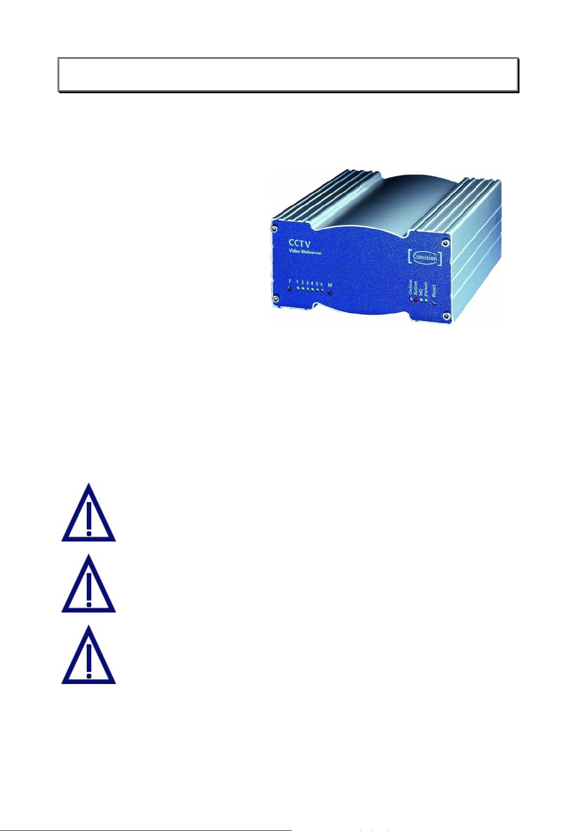
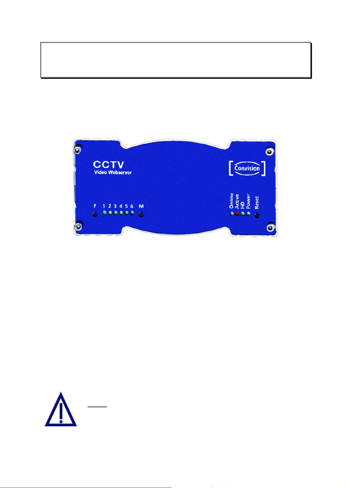
Figure 1: Front view of the Convision V6xx A
♦ F button: deletes the hard disk.
♦ LEDs 1-6: these light up when a camera is connected to the corresponding port;
they flash when the respective camera is being accessed.
♦ M button: deletes the configuration.
♦ Online LED: is lit when the Convision V6xx A proactively established a
connection.
♦ Active LED: is lit when the alarm function of the Convision V6xx A has been
switched to "alert".
♦ HD LED : (HD = hard disk); is lit when data is written to or read from the hard disk
(option).
♦ Power LED: lights up as soon as the Convision V6xx A is connected to the power
supply and switched on.
♦ Reset button: when this button is activated, the Convision V6xx A is reset. This
means the Convision V6xx A is rebooted and re-initialized.
Never
Convision V6xx A as this would cause the entire software to be
deleted.
press F and M together when you switch on the
Manual - 9 -

4.2 Rear View
All the external connectors are located on the rear panel of the Convision V6xx A.
Connectors of the Convision V600 A/610 A:
♦ CAM 1 ... CAM 6: You can connect six independent FBAS cameras to these
connectors.
♦ COM 1: Serial interface: is used to control external devices, e.g. a pan/tilt camera,
weather station etc.
♦ COM 2: Serial interface: is also used to control external devices. An analog
modem can be connected to this interface.
♦ Ethernet: 10 Base T connection for operating the Convision V6xx A in a LAN.
♦ ISDN: This connector is used for operating the Convision V6xx A via an ISDN
multi-device access.
♦ Audio: This is the connector for the microphone and loudspeaker of an audio
transmission device, e.g. a door intercom system.
♦ Power switch: used to switch the device on and off.
♦ Power, 12 V DC: This is the connector for the power pack supplied with the unit.
♦ I/O Connector: This connector is for additional devices, e.g. smoke and motion
detectors (refer to Chapter 5.7).
Figure 2: Rear
view of the
Convision
V6xx A
- 10 - Convision V600 A Series
5 Connecting the Convision V600 A
Series
There are three possibilities of operating the Convision V6xx A. You can operate it
either in a Local Area Network (LAN), via ISDN or an analog modem.
For initial configuration of the unit, there is an additional direct connection option.
♦ Via a cross-connect cable, refer to Chapter 6.3.
5.1 Connecting the Unit to the Power Supply
Connect the 12 V DC plug of the power pack connecting cable to the 12 V DC Power
connector (female) of your Convision V6xx A. Connect the power pack provided with
the unit to the power supply socket using the power cable. Activate the Power switch
on the rear of the unit. The Power LED will light up.
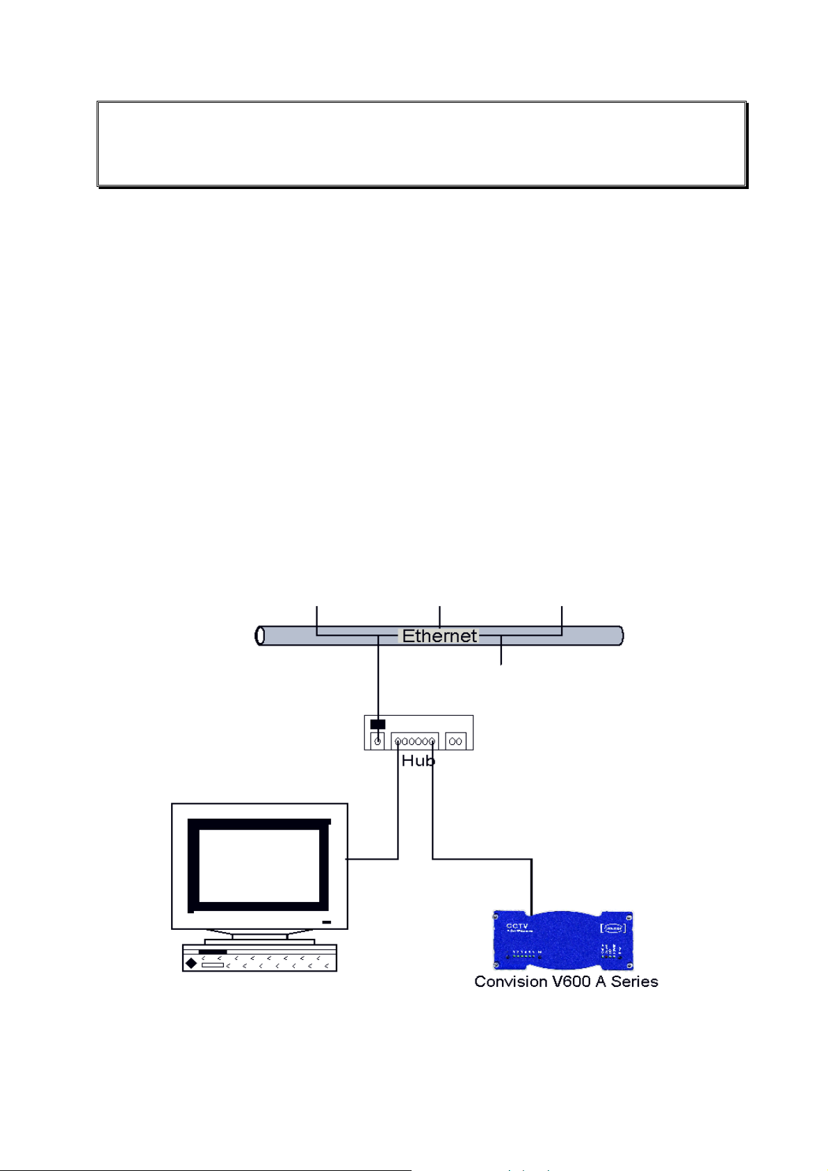
5.2 Connecting the Unit to the LAN
In a LAN, you have to establish a connection between the Convision V6xx A and
your computer via a hub or switch using a twisted-pair cable with an RJ-45
connector.
Figure 3: LAN connection
1. Connect one end of the TP cable to the Ethernet output on the rear of the
Convision V6xx A. (refer to Figure 2: Rear view of the Convision V6xx A).
Manual - 11 -
2. Connect the other end of the TP cable to one of the inputs on the hub.
3. For information on setting the IP addresses, please refer to Chapter 6.2. For
detailed information on IP addresses, please refer to Chapter 10.8.
)
Note: If you want to connect the Convision V6xx A directly to your PC, use a
cross-connect cable to connect the two devices. This is an eight-pin twisted pair
cable with crossed pin assignments (refer to Chapter 6.3).
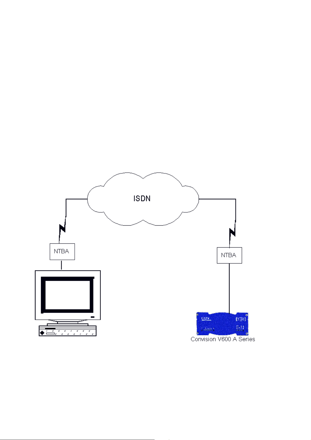
5.3 Connecting the Unit to the ISDN
Your telecommunications network operator provides ISDN access via a network
terminator (NT).
1. Plug one end of the ISDN cable provided (labeled "ISDN") into the ISDN port on
the rear of the device (refer to Figure 2: Rear view of the Convision V6xx A).
2. Plug the other end of the cable into the RJ-45-connector (female) of the ISDN
network terminator.
Figure 4: Connection via ISDN
To be able to communicate with your Convision V6xx A via ISDN, your computer
must be equipped with the appropriate ISDN hardware (e.g. ISDN card). For
information on installing ISDN hardware, please review the respective manuals of
your computer and of the device to be installed. In addition, you have to configure a
dial-up networking on your computer (refer to document “Convision System
Configuration“).
- 12 - Convision V600 A Series

Operating the Unit Connected to Telecommunications
Equipment (ISDN Telecommunications Equipment)
If you want to operate your Convision V6xx A connected to telecommunications
equipment, you have to connect the Convision V6xx A to the S
ISDN telephone that can be accessed from your computer.
For initial configuration of the unit, dial the telephone number assigned to the
telephone connected. Since this is a data call, the phone will not answer (i.e. the
phone will not ring) but the Convision V6xx A will answer the call.
-bus in parallel to an
0
) Note: In the case of telecommunications equipment it may be necessary to
enable data transmission for the access. For this purpose, contact the manufacturer
of the telecommunications equipment.
5.4 Connecting the Unit via Modem
To operate the Convision V6xx A via an analog modem, connect the modem to the
nd
2
serial interface (COM 2) of your Convision V6xx A using a serial cable. Connect
the modem to the telephone socket using the telephone cable and to the power
supply via the power pack. For information on configuring the unit, please refer to
Chapter 9.1.2.
5.5 Connecting the Cameras
Proceed as described in the following to connect one or several cameras to the
Convision V6xx A:
1. To supply the camera with 12 V DC, connect the "+" cable of the camera to the
12V DC plug, which is then connected to the 12V DC Power connector (female).
The BNC connection provides the mass connection (GND).
2. Connect the BNC connector to a camera input on the rear of the Convision
V6xx A.
Manual - 13 -
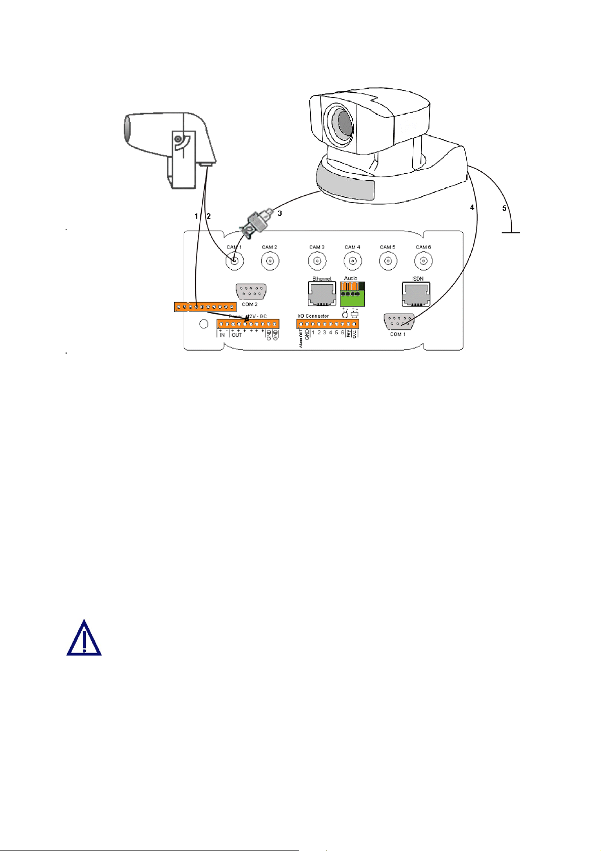
Figure 5: Camera connections
Connecting a Controllable Camera
3. Connect the video cable via the adapter supplied (Cinch on BNC) to the first
camera input on the rear of the Convision V6xx A.
4. Additionally, you have to connect the control cable (9pin Sub-D to 8pin mini DIN)
to one of the serial inputs (COM 1 or COM 2) of the Convision V6xx A.
5. The camera is supplied with power via the power pack supplied.
Define the serial input used on the Configuration / System / Device page (refer to
Chapter 9.1.11).
If you want to connect several controllable cameras to a Convision V6xx A, all the
cameras following the first one are controlled via series cable connectors of the
individual cameras (8pin mini DIN connectors). The cameras are then individually
controlled via internal port addresses.
In some controllable cameras you have to set an internal control address. For
this purpose, please use the addresses starting with "1".
For controlling a camera not supported by the Convision V6xx A you have to enable
the "Serial-URL-Port" option on the Configuration/System/Device page. For more
information on this topic, please read Chapter 9.1.11 – Serial-URL-Port. The unit is
controlled via a separate applet that can be uploaded to the Convision V6xx A (refer
to Chapter 8.6 and 9.1.4).
- 14 - Convision V600 A Series
You cannot operate 2 different types of controllable cameras simultaneously
via the Convision V6xx A.
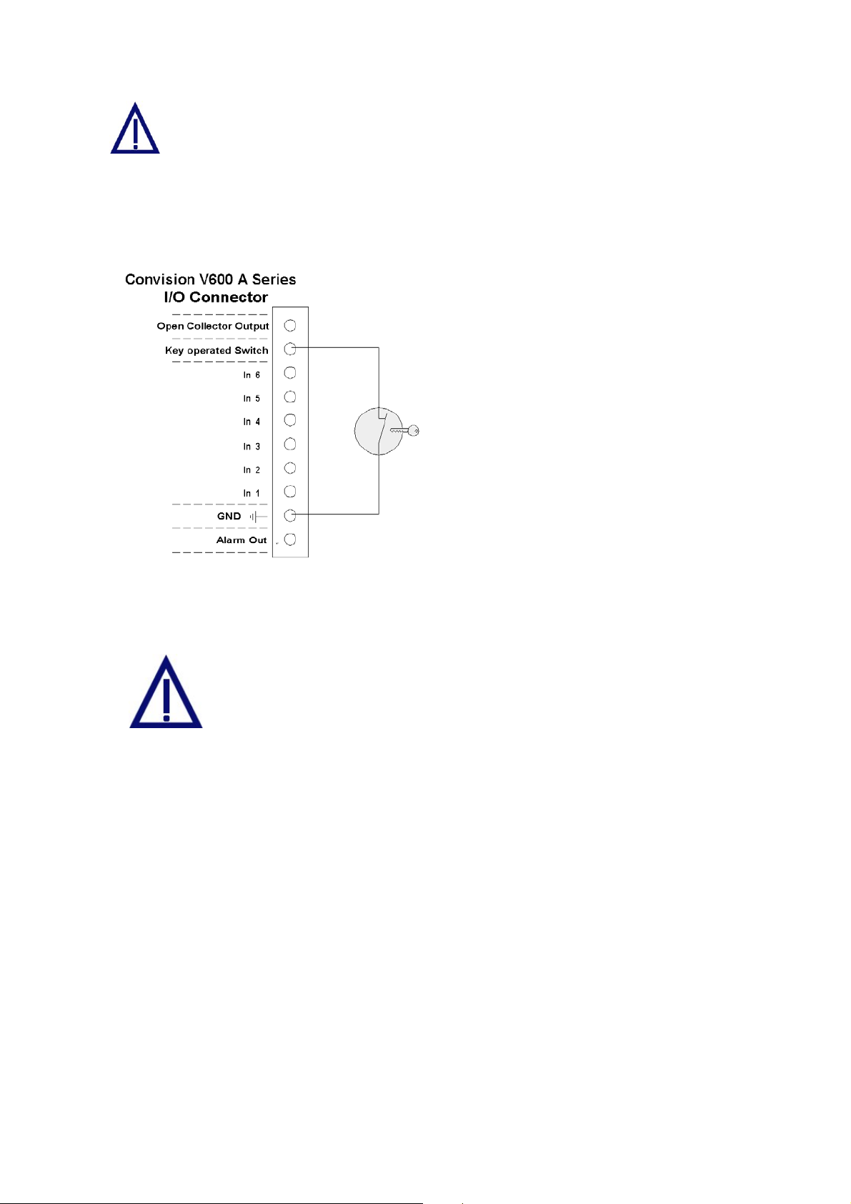
5.6 The Key-Operated Switch
The key-operated switch is connected as shown in the figure.
The key-operated switch is used to
activate the alarm function. If a keyoperated switch is not connected, the
Convision V6xx A is automatically
activated. In this case, the red "Active"
LED will be lit.
Switch unlocked Alarm function
activated
Switch locked Alarm function
deactivated
Figure 6: Key-operated switch
5.7 Input and Output Connections
Connect only devices that have been designed for 12V to your
Convision V6xx A.
Never use 230 Volts on your Convision V6xx!
5.7.1 Example: Input Connections
Alarm devices for various purposes can be connected to the six inputs. Please
observe that only 12 V devices may be connected to the inputs.
Since the inputs respond to low/high level changes, the components must be closed
in the idle state (NC type normally closed, "break contact").
Manual - 15 -
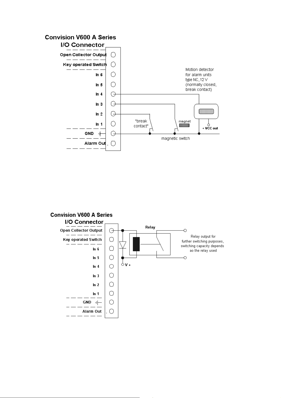
Figure 7: Example of the input connections
5.7.2 Example: Open Collector Output Connection
A relay via which higher power is then supplied, for example, can be connected to
the open collector output (OC). The breaking capacity of the OC output is
12V /100 mA.
Figure 8: Example of an OC output connection
- 16 - Convision V600 A Series
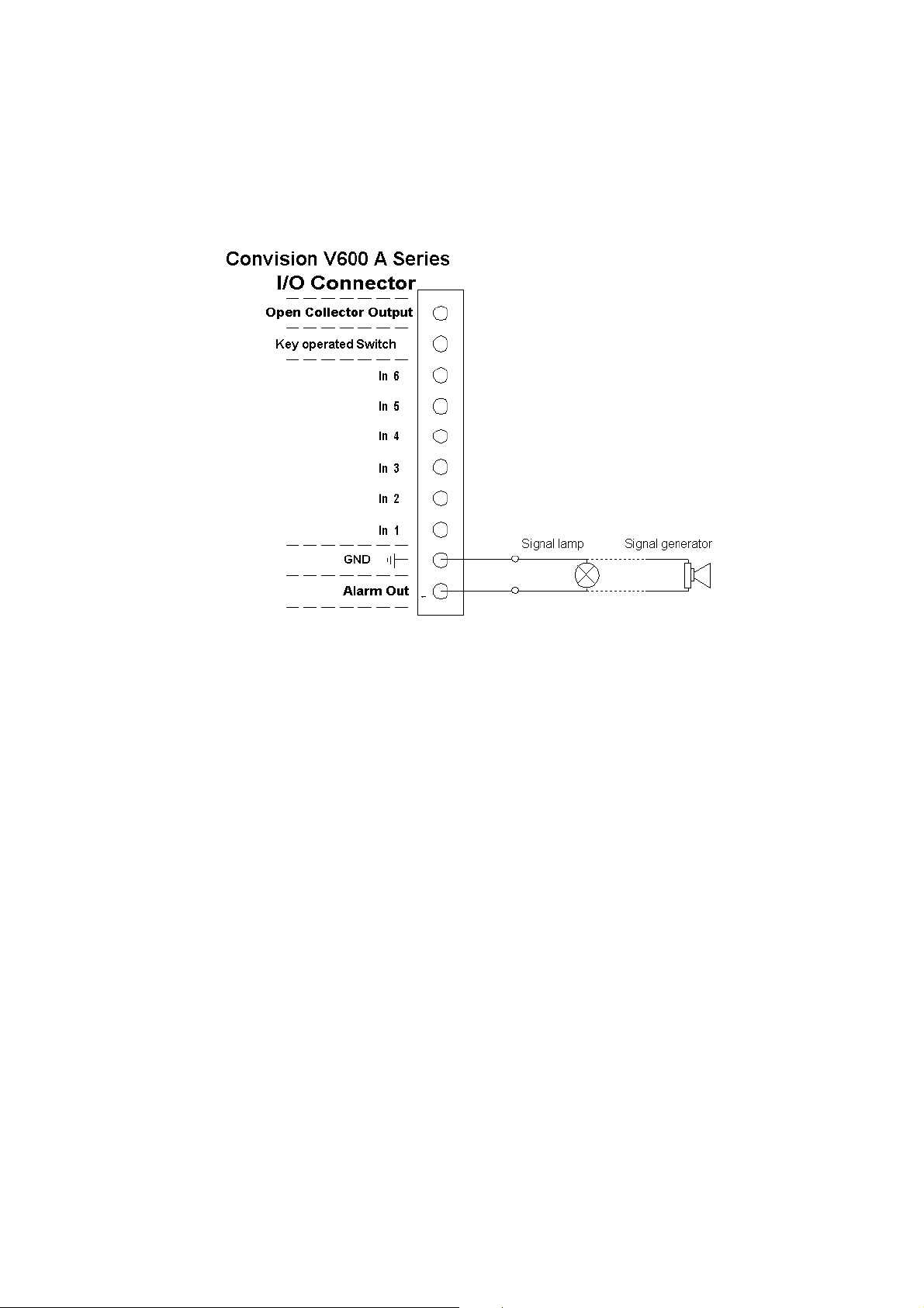
5.7.3 Example: Alarm Output Connection
An indicator lamp, for example, or any other 12 V signal device (e.g. siren), can be
connected directly to this output. The maximum load for this switching output is
12 V/500 mA.
Figure 9: Example of an alarm output connection
Manual - 17 -

6 Initial Configuration of the
Convision V6xx A
For information on the local configuration of your computer and on setting up the
browser, please refer to document “Convision System Configuration“.
To establish the first connection with the Convision V6xx A, please follow the
configuration procedure in this chapter. If you have already succeeded in establishing
a connection with the Convision V6xx A, you can skip this chapter. To customize the
configuration of your Convision V6xx A, refer to the detailed description of the
configuration options in Chapter 8.8. There, you will find a description of the menus
and buttons together with their functions.
When delivered, the Convision V6xx A is not configured, i.e. it has not been assigned
an IP address or MSN (multiple subscriber number). This is indicated by the slowly
flashing Online LED following the booting procedure. For this reason, the unit must
be configured . The configuration software "IPSetup" is on the "Products + Partners"
CD in the "Software" folder.
There are three different ways to set up the Convision V6xx A depending on your
connection.
1. MSN configuration via ISDN
2. IP configuration in a local area network
3. IP configuration via a direct link between the PC and the Convision V6xx A using
a cross-connect cable
6.1 MSN Configuration via ISDN
To set up the Convision V6xx A via ISDN, you have to install a dial-up networking on
your computer. For information on this topic, refer to document “Convision System
Configuration“.
Once dial-up networking has been configured for establishing a connection to the
Convision V6xx A, you can set up the unit. To connect to the Convision V6xx A,
establish a dial-up connection. Do not enter a username or password (refer to PPP
Password, Chapter 9.1.2) and click the "Connect" button. The ISDN connection to the
Convision V6xx A will be established.
For operation via ISDN, the IP address 10.0.0.10 has been preset for your Convision
V6xx A but you can change it.
1. Start your browser and enter
display the homepage of the Convision V6xx A.
2. Click the "Configuration", "Connections" and "ISDN/Modem" buttons one after the
other.
3. Enter the multiple subscriber number (MSN) assigned.
- 18 - Convision V600 A Series
http://10.0.0.10 as the URL. Your browser will
4. If defined, enter the PPP password to prevent unauthorized connection setup.
5. Save the data.
If you operate more than one piece of ISDN equipment on one ISDN
connection, you have to assign each unit a separate MSN number to prevent
conflicts.
6.2 IP Configuration in a Local Area Network
Follow the installation procedure below to set up the Convision V6xx A in the LAN:
1. Install and configure your LAN network (refer to document “Convision System
Configuration“).
2. Integrate the Convision V6xx A into your LAN network as described in Chapter
5.2.
3. Copy the configuration software "IP Setup" from the CD into a directory on your
computer.
4. Open the Convision IPSetup program. For this purpose, the computer must be in
the same network segment (defined by the network mask) as the Convision V6xx
A . In Windows, the program is launched using "IPSETUP.EXE".
As this is a Java program, it can also be started by opening "java IPSetup".
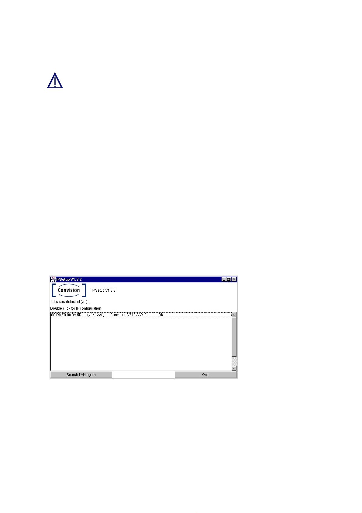
5. After a few moments (max. 1 min) the program will display the Convision V6xx A.
If the program is not automatically started, double-click the entry and then enter
the IP address and the network mask. (For more information about IP addresses
and network masks refer to Chapter 10.8).
Figure 10:
Initial configuration
using Convision
IPSetup
6.3 IP Configuration via a Direct Connection
Using a Cross-Connect Cable
The following hardware and software is required to set up the Convision V6xx A via a
cross-connect cable:
♦ an Ethernet cross-connect cable
♦ a computer with an Ethernet network access
Manual - 19 -

♦ the CD containing the IP Setup software for the Convision V6xx A
Next follow the instructions below:
1. Connect the Convision V6xx A directly to the LAN card in your computer using a
cross-connect cable.
2. Copy the configuration software "IP Setup" from the CD to a directory on your
computer.
3. Open the Convision IPSetup program. In Windows, the program is launched
using "IPSETUP.EXE".
As this is a Java program, it can also be started by opening "java IPSetup".
4. After a few moments (max. 1 min) the program will display the Convision V6xx A.
Double-click the entry and enter the IP address and network mask. (For more
information about IP addresses and network masks refer to Chapter 10.8).
6.4 Deleting the Configuration
If you made a mistake in programming the IP address, network mask or gateway or if
you have forgotten your password, you can no longer contact your Convision V6xx A.
However, in this case, you can delete the configuration by resetting the unit. Once
the Convision V6xx A has been reset, it will be in the initial state, i.e. neither the IP
address nor the MSN have been saved yet.
To delete the configuration of the Convision V6xx follow the instructions below:
1. Briefly press the Reset button on the front of the Convision V6xx A.
2. Then immediately press the "M" button and release it only after the LEDs 1, 2 and
3 have lit up one after the other. If you also want to delete language modules,
other modules and applets that you have already loaded, keep the "M" button
pressed until the LEDs 1 to 6 have lit up.
3. Then release the "M" button.
4. The configuration has been deleted when the Online LED starts blinking in
intervals of one second after the rebooting procedure. The initial configuration
procedure then needs to be repeated.
Caution! Do not press the "F" button at the same time as the
"M" button since this will delete the entire software (firmware)
of the Convision V6xx A!
- 20 - Convision V600 A Series

7 The HTML Pages – Operation and
Configuration
After the first successful connection, enter the IP address of your Convision V6xx A
in the address line of your browser.
The Homepage
The homepage of the Convision V6xx A will be displayed. From this page, you can
access all the viewing and configuration pages.
On the left-hand side you can see the navigation menus for opening the various
pages. At the bottom of this section you will find all the available languages.
On the right you can see a view of the images from all cameras.
Selecting the Language
The language selected upon delivery is either the default language set in the browser
or English. If you want the menus to be displayed in a different language, you have to
select this language at the bottom of the homepage.
In the Configuration / System / Language menu (refer to Chapter 9.1.3) you can
change the default settings and load additional languages.
Useful Notes on Navigation
In the left-hand bar of the browser window, you can see a field with the entry
"Cameras". Click the arrow to the right of this field to display a list of various menu
items. If you click on one of the menu items, another list with submenu items will be
displayed.
A small square to the left of a list item means that this entry is not
subdivided further. Clicking on this list entry will display the associated
page in the right-hand area.
A triangle to the left of the list entry means that there are more submenu
items that can be displayed by clicking with the mouse. Clicking on
these items displays the associated pages.
For the "Configuration" menu, there is another drop down menu below the first one.
This drop down menu contains the items of the individual configuration menus. To be
able to use all the possibilities provided by the Convision V6xx A, you have to
configure it first. For this purpose, please read Chapter 9 - Configuration.
Manual - 21 -
8 Operation
8.1 Cameras
In this menu you can view the images from the connected cameras.
Selecting the Viewing Mode
There are various modes for viewing the camera images. Select the viewing mode by
clicking on it:
♦ Single Shot (JPEG)
♦ Live-optimized with Server Push (Netscape only)
with ActiveX (Internet Explorer only)
♦ Live-compatible with the Java applet developed by Convision
Technology
A list of the cameras and multiple views is displayed.
)
Note: A signed Convision Systems ActiveX Plugin for displaying live streams in
Internet Explorer is available (for more information refer to document “Convision
System Configuration“).
Selecting the Camera
Select one of the individual cameras, or "View of two cameras" (views of 2 cameras
simultaneously), "View of four cameras" (views of 4 cameras simultaneously) or
"View of six cameras" (views of 6 cameras simultaneously). On the right-hand side,
the current image is displayed as 384x288(fullsize). The camera name is displayed
inside the frame, provided you assigned a name under "Configuration / Cameras /
Name".
This icon is displayed if one of the inputs is not connected to a
camera.
If you have selected views of two, four or six cameras, you can select an individual
camera by clicking the respective number button above the image. Cameras 1 and 2
or 1 to 4 are displayed by default.
Selecting the Image Size
Select the image size by clicking one of the three image sizes displayed underneath
the image:
♦ 192 x 144 (halfsize)
♦ 384 x 288 (fullsize); this is the default size
♦ 768 x 576 (hugesize)
- 22 - Convision V600 A Series
When selecting views of multiple cameras, it is not possible to change the image
size.
) Note: The loading time for a large image is longer than for a small image.
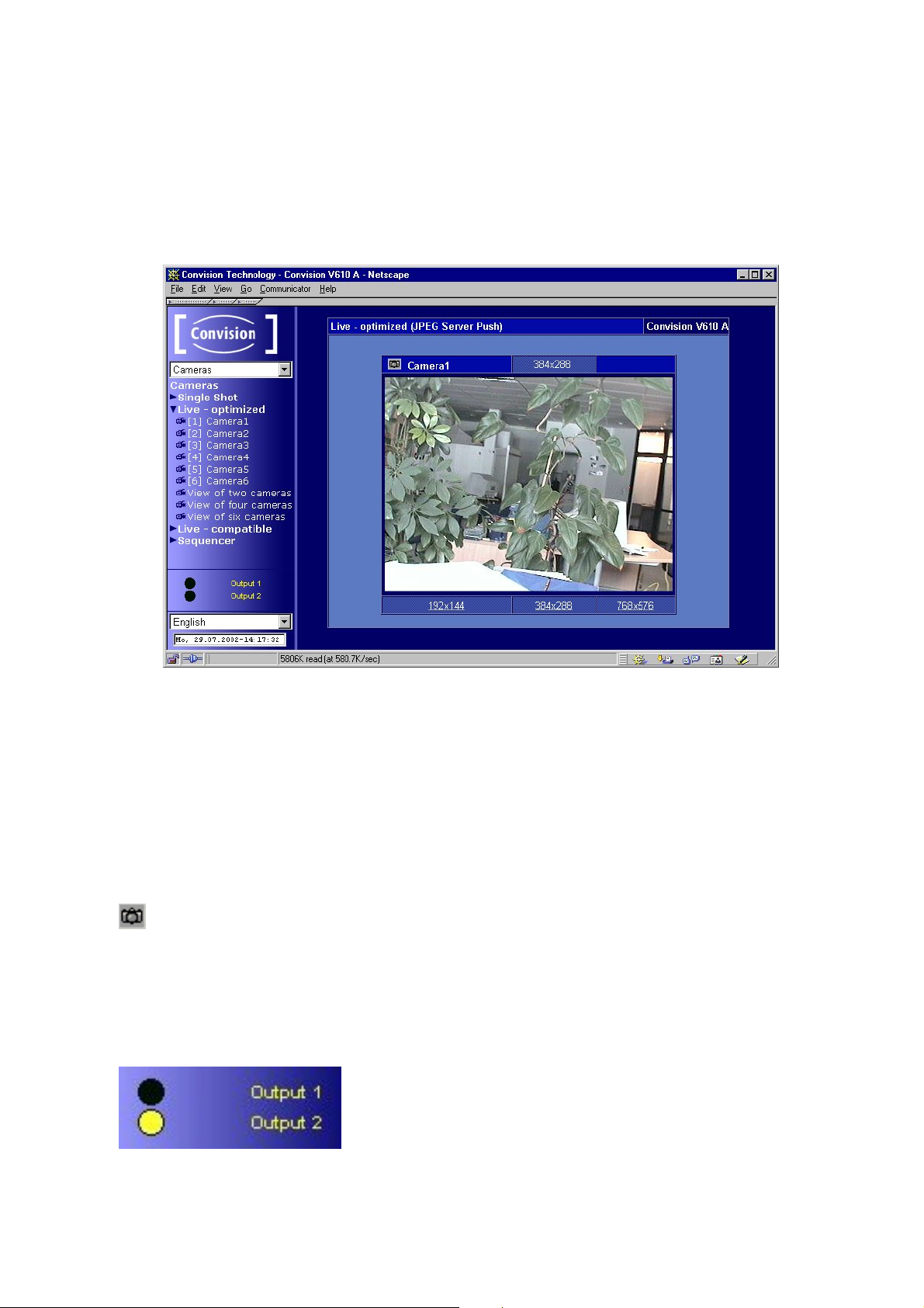
Display
Figure 11: Camera display
When the images are displayed using Live-optimized ActiveX plugin or Livecompatible, you can access a pop-up menu (to display it, click the image using the
right mouse button). This pop-up menu provides options for showing/hiding the date
and time and for starting/stopping the image stream. When using Live-compatible,
you can also flip the image horizontally and vertically and show the camera name
and FPS (frames per second) rate.
Snapshot
In the upper left hand corner of the image in the streaming section you will find
the Snapshot icon. Clicking on this during the streaming will result in a JPEG single
image being taken. With the right mouse button you can save this in the context
menu of your browser.
Activating the outputs
You can activate the outputs by clicking on Output 1 or
Output 2. A black dot indicates that the output is not
activated or has been deactivated, a yellow dot that the
output has been activated.
Manual - 23 -
The “Output (Time)” function, ie automatic activation of the outputs for a
specified time as an action following an event, overrides this function. It is
possible that you will see an inactive output here which has, in reality been
activated by an event.
8.1.1 Controllable Camera
You can connect various controllable cameras to the Convision V6xx A, which can be
operated directly via the user interface. Depending on their designs, these cameras
have different functions. For this reason, the user interface of the Convision V6xx A
varies, depending on the camera connected.
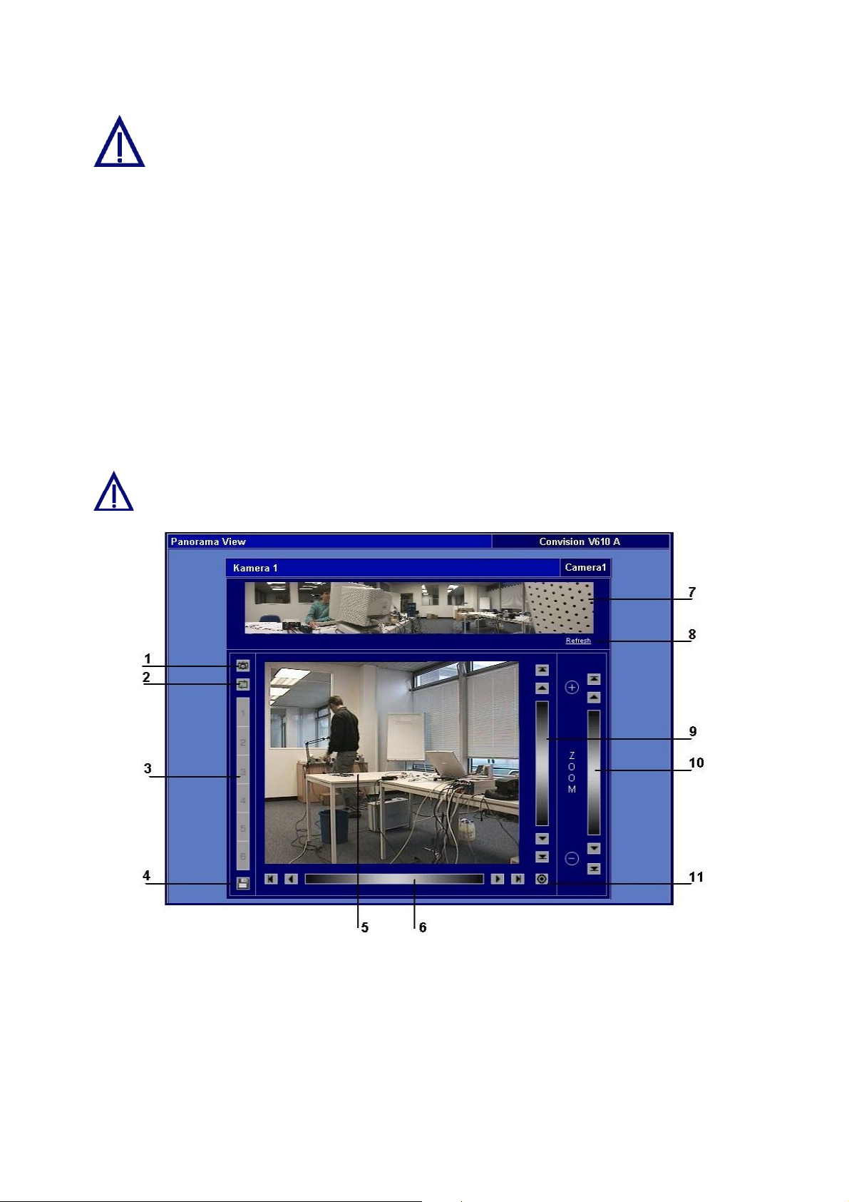
The user interface of a fully controllable camera is shown in Figure 12.
)
Note: The camera control is always displayed as a live stream with a fullsize
image recorded from a single camera.
In some controllable cameras you have to set an internal control address..
For this purpose, please use the addresses starting with "1".
Figure 12: View of a fully controllable camera
1 Snapshot - Clicking on this during the streaming will result in a JPEG single
image being taken. With the right mouse button you can save this in the
context menu of your browser.
2 Preset Tour - The camera can be pre programmed for up to 6 different position
presets which will be displayed sequentially.
3 Camera presets– storage spaces for selected image sections.
Click on the previously stored preset values to focus the camera on those
- 24 - Convision V600 A Series
sections.
4 Save button– opens a dialog box for storing the preset sections.
5 Current camera image – Click a point in the image to focus the camera on the
selected point.
6 Horizontal pan range – infinitely variable panning
Stepwise panning left/right, depending on the zoom factor
Panning to left/right end position
7 Panoramic view of the entire pan/tilt area.
8 Clicking on "Refresh" reconstructs the panoramic view using updated frames.
9 Vertical pan range – infinitely variable panning
Stepwise panning up/down, depending on the zoom factor
Panning to the upper/lower end position
10 Zoom – infinitely variable zooming
Zoom in/zoom out stepwise
maximum zoom factor/minimum zoom factor
11 Travel to the home position of the camera.
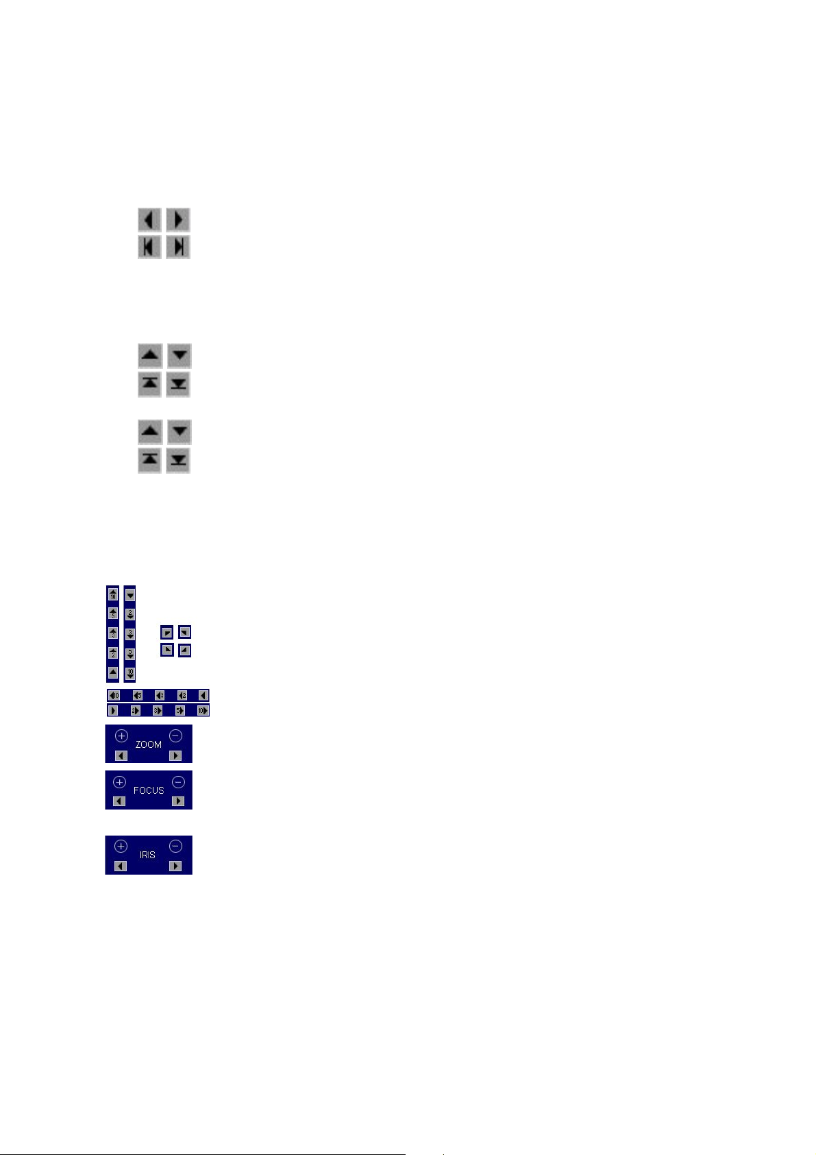
Depending on the type of camera connected, some of the following controls will be
displayed instead of the user interface shown in Figure 12: View of a fully controllable
camera.
By clicking on the triangles the camera swivels in the direction of
the arrow. The angle depends on the zoom factor.
By clicking on the double arrow, the camera will be moved 10
times further in one movement than with the single arrow.
Adjusting the zoom factor
Zoom in/Zoom out
Setting the image sharpness range for cameras without auto
focus.
Close-up focus / remote focus
Adjustment of the light incidence in the lens.
Closed iris/open iris
Saving Presets
)
Note: If the configuration protection function is activated, administrator rights are
required for the storage process.
1. For some controllable cameras you can save specific image sections as preset
sections (Presets). For this purpose, focus on the desired point within the pan
area of the camera.
2. Set the desired zoom factor.
Manual - 25 -

3. Click the diskette icon. A dialog box for saving the current image section related
to a position number is displayed.
4. Click the desired position and assign it a name.
5. Save the data. The dialog box is closed.
Now you can always focus on that point by clicking the respective position number.
The names will be displayed as a tool tip whenever the mouse cursor is positioned
on the number. The preset sections can also be addressed due to an event (refer to
Chapter 9.3).
Preset Tour
1. Configure the desired presets.
2. Click on the icon
3. Click on the desired number position and input the desired amount of time.
4. Save the data.
5. Start the “Tour“ by clicking on start. The black indicator and the ”Tour“ icon will
change to red.
6. End the “Tour“ by clicking on “stop“. The red indicator and the “Tour” icon will
change to black.
)
Note: If the configuration protection function is activated, administrator rights are
required for the storage process.
. This opens a dialogue box.
8.1.2 Sequencer
The sequencer allows you to program the cameras to be viewed sequentially for a
specified time, without having to manually shift between the cameras.
Configuration
♦ Click the activation box before each camera you want to view.
♦ Input the time in seconds you want to view the camera for.
♦ Save the data.
You can also set the sequencing configuration in the
“Configuration/Camera/Sequencer“ menu.
Start sequencer
♦ Click on either Live-optimised or Live-compatible. You will see the images,
depending on your browser configuration, either in Live-optimised or Livecompatible mode.
Stop sequencer
♦ Click on “Save“ in the configuration menu
- 26 - Convision V600 A Series
8.2 Playback (Convision V610 A only)
In the "Play" menu you can view the images saved on the available partitions.
Requirements
♦ First of all, you have to create at least one partition on the hard disk (refer to
Chapter 9.5.1).
♦ Start a recording (to start a recording manually, refer to Chapter 8.3, for a time-
controlled or event-controlled start, refer to Chapter 9.3).
♦ After images have been stored on at least one partition, start the playback
function.
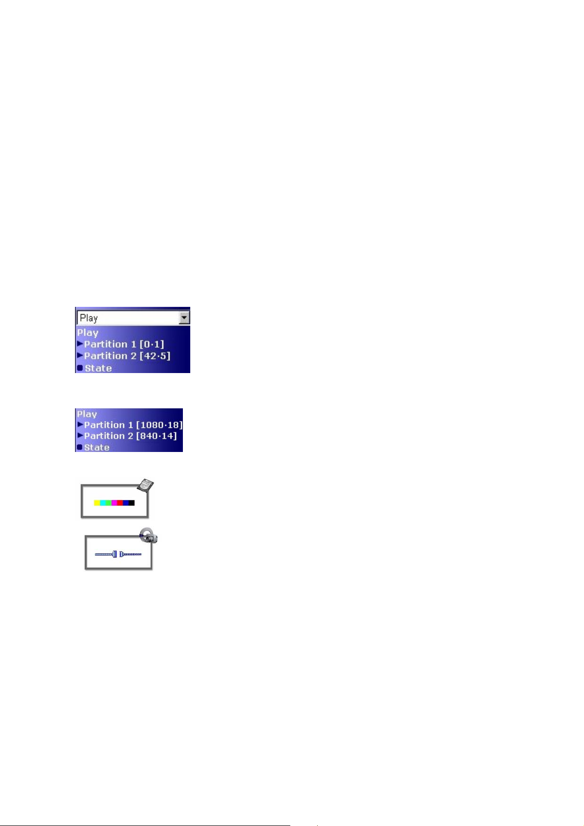
Description of the Numbers behind the Partitions
Long time partition
The numbers in square brackets behind the partition
specify: [the number of recorded images per camera •
the number of cameras recording on this partition]
In our example, the total number of images on partition 2
is 42 x 5 = 210
Event partition
1. Select the desired partition.
2. Select the desired camera and the program to be used for displaying the images,
i.e. either Live-optimized or Live-compatible refer to Chapter 10.2).
The numbers in square brackets behind the partition
specify: [the number of recorded images • the number of
events which have already occurred]
In our example, the number of images per event on
partition 2 is 840 / 14 = 60
If a partition does not have any images, the icon shown
on the left-hand side is displayed.
If a camera should temporarily fail, the icon shown on
the left-hand side is displayed. If there are several
cameras recording on a partition, the symbol will appear
for each image the failed camera should have recorded.
Manual - 27 -

Playing Back Long-Time Recordings
Figure 13: Playback
The images can be viewed in single steps or at different speeds forwards and
backwards. For this purpose, use the control panel underneath the image.
Description of the controls:
1 2 3 4 5 6 7
1 – to the beginning
2 – single step backwards
3 – backwards at normal speed
5 – forwards at normal speed
6 – single step forwards
7 – to the end
4 – stop
1 2 3 4 5 6 7
1 – backwards at 8 x the speed
2 – backwards at 4 x the speed
3 – backwards at double speed
5 – forwards at double speed
6 – forwards at 4 x the speed
7 – forwards at 8 x the speed
4 – continuous playback at normal
speed
- 28 - Convision V600 A Series

1 2 3 4 5 6 7 8
1 – backwards at 1/16
2 – backwards at 1/8
3 – backwards at quarter of the speed
4 – backwards at half the speed
th
of the speed
th
of the speed
5 – forwards at half the speed
6 – forwards at quarter of the speed
7 – forwards at 1/8
8 – forwards at 1/16
th
of the speed
th
of the speed
Use the percentage specifications below the image for fast access to the desired
image in the image sequence. 100 % refers to the last of the images recorded on this
partition, irrespective of the partition size.
)
Note: The playback speed depends on the recording speed!
Playing Back Event Partitions
The control panel also contains a list of all the recorded events. These are numbered
and identified by the date and time of the recording. Click an event to play back this
event.
Figure 14: List of Events
Manual - 29 -

8.3 Recording (Convision V610 A only)
Use the "Record" menu to manually start or stop long-time or ring buffer recordings.
Requirements
♦ First of all, you have to create at least one long-time partition on the hard disk
(refer to Chapter 9.4.9).
The table displays the created partitions along with the type of partition and the
assigned cameras.
Click "Start recording" or "Stop recording" to start or stop the recording process on
long-time recording partitions type
On the other partitions (types
stop recordings in progress.
For information on time-controlled and event-controlled recordings, please refer to
Chapter 9.3.
or ring buffer partitions type .
and ) you can neither start recordings nor
Figure 15: Menu for manual recording
8.4 Frame Buffer Display
Frame Buffers are storage spaces in the main memory of the Convision V6xx A. In
these buffers you can store as many as 32 pre and post event images per camera.
Each camera is assigned one frame buffer. This means, images recorded by camera
1 are exclusively stored in frame buffer 1 etc. Any one event can be stored in several
frame buffers. Each frame buffer can store multiple events.
- 30 - Convision V600 A Series

Requirements
♦ Configure and activate the frame buffers by selecting the Configuration menu in
the first drop down menu and Frame Buffer in the second drop down menu. Then
select Frame Buffer in the menu displayed (refer to Chapter 9.4.2).
♦ An event that you assigned the recording in a frame buffer as an action has
occurred.
If the above requirements have been met, the images stored in this buffer will be
displayed.
Figure 16: Displaying the images in the frame buffer
1. Select a camera (frame buffer).
2. The pre event images are displayed at the top, the first image is displayed
enlarged in the center of the window and the post event images are displayed at
the bottom.
3. Clicking on an image will enlarge it.
)
Note: The frame buffers are automatically restarted as soon as your images are
sent by email or VdS 2465 message. The next pre event images will then be
displayed. A frame buffer that was activated but not sent will not be restarted. In this
case, all the pre event and post event images will be displayed.
State
This menu displays a status overview of the 6 frame buffers (red indicator = started,
black indicator = stopped).
Manual - 31 -

8.5 Applications
The Convision V6xx A supports various devices that can be controlled via the serial
interface, such as weather stations or controllable sockets (not included in the scope
of delivery).
8.5.1 Activating Outputs Manually
The two outputs of the Convision V6xx A, i.e. the relay switching output and the open
collector output, are normally activated via an input alarm (refer to Chapter 9.3). The
automatic switching duration is configured in the Actions / Outputs menu.
If you want to trigger an action manually (e.g. activate a door opener), you can
activate the outputs via this menu.
)
Note: Whilst viewing the camera images, it is also possible to switch the
outputs on or off by clicking on them in the left-hand side of the window.
(see Chapter 8.1).
♦ On Switch is closed – device is activated
♦ Off Switch is opened – device is deactivated
♦ Trigger Enter a time in the "Seconds" field and click "Trigger". The
switch will close for this time and then open again.
Figure 17: Configuring the outputs
If an output activated via this switch is additionally triggered by an event, it
will remain deactivated even after the set time period has elapsed.
8.5.2 Sockets
Remote controllable sockets with a serial connector supported by Convision Systems
can be controlled using a Convision V6xx A via the serial port. In this menu you can
switch the sockets on or off.
- 32 - Convision V600 A Series

For this purpose select the socket and the seriel interface (COM 1 or COM 2) under
„Configuration / System / Devices“.
8.5.3 Weather Station
If a weather station supported by Convision Systems is connected to your Convision
V6xx A, e.g. the Huger WM918, a list with all the data transferred, such as
temperature, wind speed and wind direction will be displayed. For this purpose select
the weather station and the seriel interface (COM 1 or COM 2) under „Configuration /
System / Devices“.
The data from the weather station can be sent via FTP Upload or E-Mail (refer to
Chapter 9.4).
8.6 Applets
To extend the possibilities already provided by your Convision V6xx A, you can load
your own applets with additional controllers for other devices. Depending on these
applets, the associated HTML pages will be displayed.
You can upload the applets to the Convision V6xx A via "Configuration / System /
Applet" (refer to Chapter 9.1.4).
8.7 Modules
Modules are software programs that perform various functions in the Convision V6xx
A, thus enhancing the firmware. For modules that you can upload to the device if
desired, please visit
modules, module-specific HTML pages will be displayed. Some of the modules may
also be an extension of existing HTML pages.
Each module is supplied together with a PDF document containing a description and
operating instructions.
You can upload the modules to the Convision V6xx A via "Configuration / System /
Module" (refer to Chapter 9.1.5).
www.convision.de. Depending on the functions of the individual
8.8 Information
This menu displays the current firmware version of your Convision V6xx A and the
creation date of this firmware. If a new software version is available for download at
www.convision.de, you can update your Convision V6xx A (refer to Chapter 9.1.7).
Below the date is the serial number of your Convision V6xx A. Each unit has its own
serial number. You can use it, for example, as a registration number when
connecting to the Convision Call server (refer to Chapter 9.1.2 – Convision Call).
The serial number is also printed on a label underneath your Convision V6xx A.
Manual - 33 -

9 Configuration
If the configuration protection function is activated, only the administrator is
permitted to change the settings in this menu.
9.1 System Settings
Use this menu for making general system settings. These include the connections,
security settings, uploading various files, activating the FTP server and assigning the
serial interfaces. In addition, this menu also provides the Event log. The event log
records the configurations you made, system processes and errors that occurred.
9.1.1 LAN/Ethernet Connection Data
If you want to integrate your Convision V6xx A in a LAN using a permanent IP
address, you can enter various IP addresses via this menu.
IP Addresses
Figure 18: Configuring the IP addresses
During the initial configuration using IPSetup (refer to Chapter 6.2 or 6.3), you have
already assigned an IP address and a network mask. This data is now displayed on
this page. You can change this if desired. After a change you will be prompted to
reboot the device. For this purpose, click the "Reboot" button.
)
Note: If your Convision V6xx A is connected via ISDN only, i.e. you assigned an
MSN at initial configuration (refer to Chapter 6.1), these fields will be blank. You do
not need to enter any data.
If you do not know the individual IP addresses, ask your system administrator.
The IP address must be unique, i.e. it must not be assigned to another computer in
the network. You can use the Ping command to check whether or not an IP address
is still available for the Convision V6xx A (refer to document “Convision System
- 34 - Convision V600 A Series

Configuration“). (For more information about IP addresses and network masks refer
to Chapter 10.8)
Configuration of a Port Number
The default ports for the IP video server are 80 (HTTP) and 21 (FTP). You do not
need to specify these ports. If you require another port, click on “Port“ and replace
the default settings with your own data. Save the data and reboot the video server.
Access: Write the IP address with a colon and the new port number in the address
line of the browser.
http://192.168.0.111:8050
Only change this port if you have sufficient TCP/IP knowledge.
The Router Entry:
If you are using a default router in your network to connect to the Internet, enter its IP
address in the "Router" field. All the IP addresses outside the LAN will then be
accessed via this router.
The DNS-server entry:
In this field you have to enter the IP address of a DNS (Domain Name Service)
server (a DNS server converts an alphanumeric address to an IP address). In this
case, you should select the DNS server of the provider set in the Convision V6xx A.
For information on this topic, please revert to your provider.
Syslog Server
If you are operating a syslog server in your network, the Convision V6xx A can send
messages/error messages to the IP address of this syslog server. If your network
does not include a syslog server, this field should remain empty.
The default port for a syslog server is 514. If you have set up your syslog server on
another port, you can change this in the “Port” section.
)
Note: It makes sense to specify a syslog server only if it can be accessed via the
Ethernet.
Mail Server
The mail server must be specified if you are intending to send e-mails or SMS via the
LAN connection to the Internet. If you want to send mail via an ISDN connection, you
have to enter the respective data via the ISDN/Modem item.
Manual - 35 -

Figure 19: Configuring the mail server
1. Enter a DNS server (refer to Chapter 10.8 – The Domain Name Service).
2. Now enter the SMTP server (mail server) of the LAN or your provider.
3. Enter the address of the sending Convision V6xx A. This address must be
registered with the provider.
4. Select the authentication method as required by the provider.
5. Enter the user name and password (refer to Chapter 10.6).
9.1.2 ISDN/Modem Connection Data
If the Convision V6xx A is operated via an ISDN connection or a modem, enter the
connection data via this menu item. The Convision V6xx A can be connected either
via ISDN or via an analog modem. It is not possible to operate the two connections at
the same time.
The user can only establish a connection to the Convision V6xx A if both the
user and the Convision V6xx A are using either analog connections or ISDN
connections. Data transmission from an analog modem to ISDN is possible
only over Convision Call.
)
Note: Please check whether you need to enter additional zeroes for your
telephone system.
General
Every time you change or update something in this menu, you will be asked to restart
the Convision video server to save the changes. Click the “Reboot” button to do this.
Setting the IP Address
The IP address preset for devices accessed via ISDN connections is 10.0.0.10. If you
want to access multiple devices via the same ISDN connection and a router, you can
- 36 - Convision V600 A Series

enter further addresses and network masks. After a change you will be prompted to
reboot the device. (For more information on IP addresses and network masks refer to
Chapter 10.8.)
PPP Host Name
As a rule, routers identify IP video servers by the MSN. However, some routers also
use the host name for the device. The default name is “ConvisionVideoWebserver“,
but you can change this here.
Selecting ISDN or Modem
Use one of these two buttons to specify whether your Convision V6xx A is connected
via ISDN or a modem.
ISDN Connection to the Convision V6xx A
Figure 20: Configuring the ISDN parameters
1. In the "Phone number (MSN)" field, enter the multiple subscriber number (MSN))
for dialing the Convision V6xx A.
)
Note: Normally, when using a telephone system, you have to enter only the
extension as the telephone number.
2. Enter the login name in the "Identification for PPP" (point-to-point protocol) field.
3. Enter the password in the "Password for PPP" field.
)
Note: The data you enter in these fields must also be entered in dial-up
networking when establishing an ISDN connection (refer to document “Convision
System Configuration“).
)
Note:
reasons if the Convision V6xx A is addressed directly via an ISDN connection
because a connection can be established even if access to the device is protected by
the user password (refer to Chapter 9.1.8).
The login name and the user password are advisable for security
Manual - 37 -

4. If supported by your provider, activate the password encoding option if desired
(refer to Chapter 10.4).
5. If supported by your provider, activate the channel bundling option if desired (refer
to Chapter 10.5).
When setting up dial-up networking, than you have to enable multi-channel
connection setup (refer to document “Convision System Configuration“).
6. Save the data.
7. You will be prompted to reboot the device. For this purpose, click the "Reboot"
button.
Connecting to Different Providers
The Convision V6xx A needs the connection data to be able to establish a
connection via a provider, e.g. to send e-mail,
to perform an FTP upload or
to establish a connection to Convision Call.
While connected to a provider, the Convision V6xx A cannot be accessed via
the default router.
By entering multiple providers, it is possible to establish alternative connections
automatically, if the first attempt at establishing a connection fails. Apart from that,
you can select different connections for different tasks.
1. Select one of the eight connection buttons on the "Connections" button bar.
2. Assign a name.
3. Enter the phone number of the provider.
4. Enter the login name in the "Identification for PPP" (point-to-point protocol) field.
5. Enter the password in the "Password for PPP" field.
6. If supported by your provider, activate the password encoding option if desired
(refer to Chapter 10.4).
7. If supported by your provider, activate the channel bundling option if desired (refer
to Chapter 10.5).
When setting up dial-up networking, you have to enable multi-channel
connection setup (refer to document “Convision System Configuration“).
- 38 - Convision V600 A Series

Figure 21: Configuring connections
8. TimeOut specifies the time period the Convision V6xx remains connected to the
provider after the last data has been transferred. 55 seconds is the default time
period. If desired, enter a different time in seconds (max. 99999 seconds).
9. Deactivate the checkbox if you want to terminate the connection immediately after
the last data has been transferred or upon interruption of the data stream.
10. Enter the DNS server of the provider (refer to Chapter 10.8 – The Domain Name
Service).
The following data needs to be entered only if you want to use this connection for
sending e-mail or SMS!
11. Enter the SMTP server (mail server) of the LAN or your provider.
12. Enter the address of the sending Convision V6xx A. This address must be
registered with the provider.
13. Select the authentication method as required by the provider.
14. Enter the user name and password (refer to Chapter 10.6).
)
Note: If your provider does support channel bundling but it is not possible to
bundle the two lines, the connection will be terminated with an error message in the
status display (refer to Chapter 9.1.12).
Manual - 39 -

Configuring the Modem
In the "Analog Modem" menu you will find settings for a modem that supports the
extended Hayes command set.
The init strings for initializing the modem depend on the modem used. The init strings
for your device can be found in the operating instructions of your modem.
Make sure that you have chosen “Modem” under „Configuration/System/ISDNModem/General”.
1. Enter the login name for identification for PPP.
2. Enter the PPP password.
3. If the values for your modem differ from the settings, please enter the correct
strings.
4. Save the data and reboot your device.
5. If you made a mistake, click "Default" to restore the settings.
After changes to this data, you have to reboot your Convision V6xx A.
Audio/Voice Transmission via ISDN
Apart from data transmission, the Convision V6xx A can also be addressed via a
telephone line. Audio data are transmitted via the B-channel of the ISDN. For this
reason, you have to connect the Convision V6xx A to the ISDN. The image data are
transmitted either via Ethernet or via the other B-channel. In this case, channel
bundling is no longer possible.
Connect a door intercom system to the audio connector (female) on the rear of the
device (refer to Figure 2: Rear view of the Convision V6xx A.)
1. For this purpose, remove approx. 10-13 mm of the insulation of the microphone
and loudspeaker cables.
2. Using a small screwdriver, press against the clamping device above the
receptacle and push the twisted cable into the receptacle.
3. After releasing the clamping device, it retains the cable. Check for tight seating by
easily pulling on the cable.
4. Enter the MSN of the Convision V6xx A in the "Audio" field.
5. Specify up to 5 telephone numbers that are to be permitted to call the Convision
V6xx A. Enter the first number in the first field. When entering the telephone
numbers, you can use "*" as a wildcard at the end of the number. This character
can stand in for one or multiple end numbers.
6. Save the data.
- 40 - Convision V600 A Series

You can now call the Convision V6xx A.
Figure 22: Audio connections
) Note: The automatic number identification feature must be enabled at the
telephone connection of the Convision V6xx A as well as at the connection of the
calling party to ensure that the number is identified. For analog telephone
connections, the CLIP function must be enabled.
If you want to control an alarm circuit, you have to connect an alarm signaling device
to one of the inputs.
When this alarm is triggered (1), the Convision V6xx A sends an e-mail or VdS alarm
notification to a receiving station (2), e.g. an alarm center. The receiving station then
manually or automatically establishes a voice connection to the door intercom system
via the Convision V6xx A (3).
)
Note: The audio data are not transmitted synchronously to the image data.
Figure 23: Audio data transmission
Manual - 41 -

Convision Call
Convision Call is a service offered by Convision Systems GmbH so that you can
easily reach your Convision V6xx A connected via ISDN. Apart from that you save
the costs of an ISDN long-distance call since the Convision V6xx A connects to the
Convision Call server via your local Internet provider at an economical rate and with
a dynamic IP address.
)
Note: The connection costs incur on the Convision V6xx A side because it sets up
the connection.
)
Note: Only the connection setup is made via the Convision Call server, not the
data transfer.
)
Note: When selecting a connection with channel bundling to the provider (refer to
Chapter 9.1.2), only one access at a time can be made to the Convision V6xx A. For
setting up another connection, there is no other free B-channel for signaling.
To be able to use this service, you need register with the Convision Call server. This
connection can also be set up if the user connects via an analog modem. However,
the Convision V6xx A must be connected via ISDN.
1. Turn on Convision Call by clicking the "Activate" checkbox.
2. The IP address of the Convision Call server and the associated telephone
number has already been entered. If the installation site of your Convision V6xx A
is not in Germany, you have to enter the country code (0049).
3. To be able to use this service, you need to register with the Convision Call server.
For more information on Convision Call, please visit:
http://www.convision.de/convision/_de/convisioncall/call.html. To register, you need
the serial number of the Convision V6xx A and the connected ISDN telephone
number of the Convision V6xx. The serial number is located on a sticker underneath
the Convision V6xx A and on the HTML pages in the "Information" menu.
Registration and Configuration Convision Call
1. Use a browser to open the Convision website www.convision.de, click the
"Convision Call" button and select "Register to Convision Call – Server".
2. Fill in the registration form and save it. You are now registered with the Convision
Call server and in future you need only enter your name and password to log in.
)
Note: Please check whether you need to enter additional zeroes for your
telephone system.
3. Click "To Convision IP video server". Enter your login name and password.
4. Click on the "Add" button; enter the data of your Convision V6xx A. Save your
data. A window containing the data you just saved will be displayed.
- 42 - Convision V600 A Series

Figure 24: Configuring the Convision Call server
5. Open a second browser window and position the two browser windows in such a
way that you can access both.
6. In the 2nd browser window, open the configuration page of your Convision V6xx
A (Configuration / System / ISDN/Modem / Convision Call) and click "Control".
The Convision V6xx A will now wait for a call from the Convision Call server (for
the set timeout) to learn the phone number of the server.
Figure 25: Configuring Convision Call in the Convision V6xx A
7. Immediately (within the set timeout, refer to Chapter 9.1.2 Connecting to Different
Providers) select the "Connect" option in the first browser window. The server will
now call your Convision V6xx A. The Convision notices that it is being called but
does not answer the call. Instead, it updates (if applicable) the number of the
Convision Call server and establishes a dial connection to the Internet via the
Internet Provider.
8. Once the connection has been successfully established, the "Call received"
message will be displayed.
9. The ConvisionCall telephone number has probably now been corrected
automatically. Save the data again.
Manual - 43 -

)
Note: If you call the Convision V6xx A via dial-up networking and there are not
enough free telephone lines, disconnect dial-up networking to your Convision V6xx A
immediately after the test call.
Using Convision Call
1. Use a browser to call the Convision website www.convision.de.
2. Click the "Convision Call" button.
3. Click "To Convision IP video server".
4. Log in to the Convision Call server using your name and password.
5. Select a Convision V6xx A in the window displayed (refer to Figure 24:
Configuring the Convision Call server) and click "Connect".
6. You will be connected to your Convision V6xx A.
7. The connection will automatically be terminated when data are no longer being
transferred. If a timeout is set, the connection will be terminated only after the
timeout has elapsed (refer to Chapter 9.1.2 Connecting to different Providers).
8. Click "Connect again" if you want to re-establish the connection to the Convision
V6xx A.
VdS – Alarm Notification in Compliance with VdS 2465
Apart from TCP/IP, the Convision V6xx A can alternatively use a special alarm
protocol (VdS 2465) to send alarm messages. These messages are sent via an ISDN
connection to an alarm center. At the alarm center, a special software receives and
decodes these messages so that measures can be taken immediately.
This menu is used to define the parameters for connecting to the alarm center. The
individual messages are defined in the "Action / VdS 2465" submenu (refer to
Chapter 9.4.8).
1. Enter the telephone number of the alarm center that will answer your alarm
message.
2. Enter the VdS identification. Your alarm center provides this ID to identify your
Convision V6xx A.
3. Periodic reporting to the alarm center serves for verifying whether your Convision
V6xx A is operational.
4. Indicate at which time the monitoring message is to be sent.
5. Indicate the line for the monitoring message
VdS alarm notifications can only be sent to an alarm center with the facilities
to process these messages.
VdS alarm notifications can only be sent via ISDN.. Sending with a modem is
not possible.
- 44 - Convision V600 A Series

9.1.3 Language
Selection
By default, the Convision V6xx A menus can be displayed in German or in English.
Upon the first access to the Convision V6xx A user interface, the current browser
setting is used.
Via this menu, you can select the language or you can continue using the default
language of your browser.
For this purpose, activate the associated button.
Figure 26: Selecting the language
Upload
You can add a language version by uploading a file containing all the menu texts to
the Convision V6xx A.
Modules with other languages are available on the Convision Website
www.convision.de. Download the desired language module to your computer.
1. To upload the language module to the Convision V6xx A, enter the file name
(extension .lgf) together with the complete path to the directory in which it is
stored.
2. Alternatively you can click the "Browse" button to search for the file. Once you
have located it, double-click to add it to the input line.
3. Then click the "Upload file" button.
Do not switch off the Convision V6xx A during the upload procedure.
Do not access the Convision V6xx A in any other way during the upload
procedure.
Manual - 45 -

9.1.4 Applets
In this menu, you can load your own applets to the Convision V6xx A, e.g. for
controlling other devices via the serial interface. In the "Applets" menu (refer to
Chapter 8.6), you can display the associated HTML page. You can delete an applet
that you do not need any longer.
You can download a sample applet that you can adapt to your needs free of charge
on the Convision Website
Upload
1. To upload an applet to the Convision V6xx A, enter the file name (extension .jar)
together with the complete path to the directory, in which it is stored.
2. Alternatively you can click the "Browse" button to search for the file. Once you
have located it, double-click to add it to the input line.
3. Then click the "Upload file" button.
www.convision.de.
Do not switch off the Convision V6xx A during the upload procedure.
Do not access the Convision V6xx A in any other way during the upload
procedure.
Delete
When clicking the delete menu item, a list of all the applets you have already
uploaded will be displayed. If you want to delete one of these applets, select it and
then click the "Delete" button.
For an HTML display of your applet, select the "Applets" menu (refer to Chapter 8.6).
9.1.5 Modules
Modules are software programs that can perform various functions in the Convision
V6xx A, thus enhancing the firmware. For modules that you can upload to the device
if desired, please visit
Via the "Module" item in the "Configuration" menu, you can upload further modules to
the V6xx A, activate modules or delete them.
www.convision.de.
The HTML page of a module is displayed either via the "Module" menu (refer to
Chapter 8.7) or as an extension to an existing HTML page.
Upload
1. To upload a module to the Convision V6xx A, enter the file name (extension
.mod) together with the complete path to the directory in which it is stored.
2. Alternatively you can click the "Browse" button to search for the file. Once you
have located it, double-click to add it to the input line.
3. Then click the "Upload file" button.
- 46 - Convision V600 A Series

Do not switch off the Convision V6xx A during the upload procedure.
Do not access the Convision V6xx A in any other way during the upload
procedure.
Delete
When clicking the delete menu item, a list of all the modules you have already
uploaded will be displayed. If you want to delete one of these modules, select it and
then click the "Delete" button.
9.1.6 Configuration – Saving and Uploading
You can save all the configuration data of your Convision V6xx A in a binary encoded
file (default "convision.cfg") on your computer.
To save the file, click "Save configuration to file". Select the desired directory in the
dialog box displayed.
You can upload the saved file to other devices of the same type and thus easily
transfer the settings you made. You can also use this file to define the basic
configuration. If you made undesired changes, for example, you can easily restore
the original configuration using this file.
After you transferred the configuration file to other devices, you must assign a new IP
address/MSN.
The device associated with the IP address set in the configuration file
must not be reachable within the LAN when the file is transferred to
another device. As soon as you have transferred the file, change the IP
address if the two devices are to be reachable within the LAN at the
same time. Switch on the other device only after you have made these
changes.
1. To upload the configuration file to the Convision V6xx A, enter the file name
(extension .conf) together with the complete path to the directory, in which it is
stored.
2. Alternatively you can click the "Browse" button to search for the file. Once you
have located it, double-click to add it to the input line.
3. Then click the "Upload file" button.
Do not switch off the Convision V6xx A during the upload procedure.
Do not access the Convision V6xx A in any other way during the upload
procedure.
Manual - 47 -

9.1.7 Update – Uploading New Firmware
Via this submenu you can upload new firmware versions to the Convision V6xx A.
The software is continuously updated and its performance improved. The latest
version of the software is available for download free of charge as a ZIP file on the
Convision website
1. To update the software, enter the full path of the directory to which you unzipped
the update file on your computer after downloading.
2. Alternatively you can click the "Browse" button to search for the file. Once you
have located it, double-click to add it to the input line.
3. Then click the "Upload file" button.
Do not switch off the Convision V6xx A during the update procedure.
Do not access the Convision V6xx A in any other way during the procedure.
www.convision.de.
Figure 27: Update dialog box
)
Note: Following an update, controllable cameras may not be initialized correctly.
In this case, switch off the camera and the Convision V6xx A, then switch on the
camera first. Wait for the camera self-test to complete and then switch on the
Convision V6xx A.
- 48 - Convision V600 A Series

9.1.8 Security Settings
In this submenu you can define security measures against unauthorized access to
your Convision V6xx A. There are three levels for protecting the Convision V6xx A
against unauthorized access.
Save your data once you have entered the passwords and activated the respective
levels.
Figure 28: The three security levels
Protecting the Configuration against Unauthorized Access
If you want to protect the configuration settings against unauthorized access, enter a
password in the "Administrator password" area and confirm it. Then activate the
"Protect configuration against unauthorized access" checkbox.
Now a prompt for entering the administrator password will be displayed as soon as
the "Configuration" menu is selected. A user with the login name "admin" will always
be granted access to all the areas of the device.
The login name for the administrator is “admin” and cannot be changed.
Protecting the Recording Sector against Unauthorized Access
If you also wish to protect the recording sector, i.e. the access to the frame buffer or
the hard disk, enter a password in the "Password for recording sector" area and
confirm it. Then activate the "Protection of the recording sector" checkbox.
Now a prompt for entering the password for the recording sector will be displayed as
soon as the "Record" menu is selected. A user with the login name "record" always
has access to all the areas. An exception is the "Configuration" menu, provided it has
been password-protected.
The login name for the recording sector is “record” and cannot be changed.
Manual - 49 -

Protecting the Device against any Unauthorized Access
You also have the possibility of protecting the Convision V6xx A against unauthorized
access in general. For this purpose, enter a password in the "User password" area
and confirm it. Then activate the "Protect Convision V6xx A against unauthorized
access" checkbox.
Now a prompt to enter the user password will be displayed upon any access to the
Convision V6xx A. A user with the login name “user” cannot access the
"Configuration", "Frame Buffer" and "Hard disk" menus, provided these have been
password-protected.
The login name for the user section is “user” and cannot be changed.
9.1.9 Setting the Time and Date
The date and time are set upon delivery of the Convision V6xx A. If these settings
are not correct due to different time zones, you can change them via this menu item.
Save the data.
These two settings are constantly updated even without an external power supply via
a backup battery.
Your Convision V6xx A can automatically change from summer to winter time. The
time conversion is done in MESZ (Middle European Summer Time) and is already
configured for the next few years. If you do not require this, simply delete the
preconfigured time.
9.1.10 Activating the FTP Server
Use this menu to activate the Convision V6xx A as an FTP server. When this option
is activated, the camera images can be downloaded using either HTTP (Hypertext
Transfer Protocol) or FTP (File Transfer Protocol).
After changes to these data, you have to reboot your Convision V6xx A.
Permitting Anonymous FTP Access
If the Convision V6xx A is protected in that the various security levels have been
activated (refer to Chapter 9.1.8), it will not be possible to access it via FTP without
entering a login name and password.
You then have to use the following URL to access the Convision V6xx A:
ftp://login_name:password@IP-address/....
The login name is either "admin" or "user" and the password is the one assigned in
the security settings. Once the page has been opened, the password is no longer
displayed in the address line.
- 50 - Convision V600 A Series

If "Anonymous FTP allowed" has been activated, users are able to access the
images on the Convision V6xx A with the login name "anonymous" or "ftp" and any
password via an FTP program.
)
Note: If the FTP protocol is opened using a browser, it is not necessary to enter
the user data. The login name "anonymous" is the default setting for this access.
Figure 29: FTP-Server dialog box
Downloading Images via FTP Using a Browser
If you have activated the FTP server, you can also download the images from the
Convision V6xx A via FTP using your browser (in this case, the FTP client). To this
end, you need only specify the desired image using an FTP command. To access an
image stored on the hard disk, enter the following address in the browser:
ftp://IP-address/HD/partition1/camera1/good/123456.jpg
The path is composed of:
♦ IP address of the Convision V6xx A,
♦ specification "HD" for the hard disk area
♦ specification of the partition (partition1 –- partition8)
♦ specification of a camera (camera1 – camera6)
♦ image quality (good, medium, low)
♦ desired image. The names of the images are composed of a 6-digit serial number
and the extension ".jpg", e.g.: "001234.jpg"
The number depends on the number of recorded images in this directory.
An up-to-date image can be obtained using the following path:
ftp://IP-address/cameras/camera2/fullsize.jpg
This command addresses camera 2. For other image sizes, you can enter "halfsize"
or "hugesize" instead of "fullsize".)
)
Note: At "ftp://IP-address/HD/info.txt" you can download an overview of the hard
disk partitioning and the available images.
Manual - 51 -

9.1.11 Assignment of Devices to the Serial Ports
In the "Device" menu you have to enter the devices connected to the two serial
interfaces (COM 1 and COM 2) of your Convision V6xx A.
1. In the table displayed, select which device is connected to COM 1 and COM 2. If
no devices are connected, select "No device connected!" (default).
2. If several controllable cameras are connected, specify the number of cameras.
3. As a rule, a modem is connected to COM2. For all the other devices (controllable
cameras, weather station, controllable sockets) you are free to choose the port.
4. If you want to operate a device not listed in the table, select "Serial Url Port". You
will control the device with your own applet that you have to upload to the
Convision V6xx A (refer to Chapter 8.6 and 9.1.4).
5. Save the data.
6. You will be prompted to reboot the device. For this purpose, click the "Reboot"
button.
You cannot connect two models of one device type (e.g. cameras) to the two
COM ports.
Serial URL Port
Figure 30: Assignments of the serial ports
Once the serial URL port has been activated, it is possible to control devices not
supported by the Convision V6xx A, e.g. other controllable cameras. In this case, all
the parameters required for setting the serial connection and the actual data will be
transferred.
The data that need to be entered for controlling the device can be obtained from the
device manufacturer.
When programming a website or an applet, you can integrate links or buttons that
include CGI parameters in addition to the IP address of the Convision V6xx A in the
- 52 - Convision V600 A Series

URL. These parameters are forwarded to the device to be controlled via the serial
URL port. You can download a manual for programming the Convision Webserver
and a sample applet at
www.convision.de.
9.1.12 Event Log
The Convision V6xx A logs all the system events (information, errors and warnings).
Click on the "Event log" menu item to list all these events.
Click on "Delete events" if you want to delete the list.
Additional all events are recorded on the hard disk – refer to Chapter 9.5.6.
Figure 31: Event log
You can change or filter the display by clicking on one of the buttons above the list:
Change the order of the entries
All the entries visible and refresh the display
Filter: only events visible
Filter: only warnings visible
Filter: only errors visible
Manual - 53 -
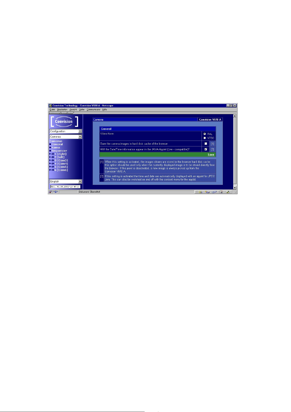
9.2 Camera Settings
In the "Configuration/Cameras" menu you can rename the connected cameras, i.e.
assign them individual names (e.g. depending on the position of the camera). In
addition, you can set the camera properties.
9.2.1 General – Settings for the Image Display
Figure 32: Gerneral camera settings
♦ Per default the video norm is PAL. If the cameras do not correspond to the
selected norm the camera images will be shown distorted.
- Select „NTSC“, if your cameras correspond to the NTSC norm.
- Save the data.
- You will be prompted to reboot the device. For this purpose, click the "Reboot"
button.
♦ Activate the checkbox if the camera images are to be saved in the "hard disk
cache" of the browser (not in Internet Explorer).
activated: The individual image displayed in the browser window can be
saved.
not activated: When saving an image, an up-to-date image from the
camera is used instead of the one displayed in the browser.
♦ Activate this checkbox to enable the display of date/time in the Java applet.
)
Note: The Java applet also has a pop-up menu (click the right mouse button on
the image) via which the date can be shown/hidden.
9.2.2 Name – Renaming Cameras
In this menu you can assign each camera a name. It is a good idea to use the name
of the location at which the respective camera is mounted. After entering the names,
click the "Save" button to save the names you assigned in the Convision V6xx A. The
names assigned to the cameras will then be displayed in the camera views.
- 54 - Convision V600 A Series

9.2.3 Pan/Tilt
This menu is displayed only if a controllable camera is connected.
In the associated dialog box you have to enter the maximum time in seconds granted
to a user for controlling a camera. During this time period, any other access to this
camera will be rejected. If a "0" is entered in this field, every access is permitted, i.e.
if several users access a camera simultaneously, one user can change the position
desired by another user.
9.2.4 Setting the Camera Properties
1. Select a camera.
This icon is displayed if one of the inputs is not connected to a
camera.
2. Select the property you want to change, i.e. either "Saturation", "Brightness",
"Contrast", "Quality" or "Hue" (for NTSC cameras only).
3. Adjust the settings according to your requirements.
♦ Possibility 1: the 6 number buttons above the image represent the various
saturation levels. Click on one of the number buttons to select this level. If you are
satisfied with the setting, click the "Save" button.
Figure 33: Setting the camera properties 1
♦ Possibility 2: if you click on the rectangle made up of six small rectangles in the
upper right-hand corner, images representing all the six levels will be displayed.
You can select the desired level by clicking on the corresponding image.
Manual - 55 -

Figure 34: Setting the camera properties 2
)
Note: If your Convision V6xx A is connected via ISDN it is advisable to reduce the
quality and thus the data volume of the images to achieve a smooth image stream.
)
Note: The hue (for NTSC cameras only) defines the color hue of the image and is
set to 128 by default. If the image does not exhibit a natural hue with this setting, you
can adapt it by slightly changing the default value.
9.3 Events – Actions When an Alarm Is Triggered
An event occurs either when an input is activated (time-dependent by timers you
configured), when an internal event occurs or when a camera detects and reports an
activity.
These menu items are used to configure the events. You then assign actions to the
events that are to be triggered as a response. The following actions may be possible:
♦ CameraPresets (at least one controllable camera must be connected)
Activate the preset positions that are to be taken. These
positions will be taken directly one after the other in the order
listed.
♦ Hard disk (Convision V610 A only)activate the checkboxes of the
partitions you want to record to.
♦ Frame Buffer Activate the checkboxes of the frame buffers that are to be filled
but not sent. If you want to append frame buffers to an e-mail or
VdS notification, you must not enter them here.
♦ Camera Tour (at least one controllable camera must be connected) Here you
can start or stop the camera tour that was previously configured
under either Camera/Live Optimized or Live Compatible.
♦ Output (Time) – Activate the checkboxes of the outputs that are to be
switched for the time period set.
- 56 - Convision V600 A Series

♦ Output (Start+Stop) – Activate the checkboxes of the outputs that are
to be switched during the alarm.
♦ FTP Activate the checkboxes of the FTP uploads that are to be
performed.
♦ eMail Activate the checkboxes of the e-mails that are to be sent.
♦ eMail State An e-mail with informations about the state of the device will be
sent.
♦ SMS Activate the checkboxes of the SMS that are to be sent.
♦ VdS2465 Activate the checkboxes of the VdS 2465 notifications that are
to be sent.
♦ Activity Detection If you want to start or stop activity detection, activate the
corresponding box.
9.3.1 Inputs
You can connect various signaling devices to the inputs of the Convision Video
Webserver. Use this menu item to assign each input (Input 1 to Input 6) the actions
that are to be performed when a message is received.
Figure 35: Configuring the alarm inputs
1. Enter the name of the input.
2. Click on an input in the first table column. A page with a weekly schedule is
displayed.
3. Now define one or two time periods for each day of the week on which this input
is to be active. Enter start and stop times for the respective days of the week.
Manual - 57 -

Figure 36: Configuring the inputs – weekly schedule
4. If you want to have a set period of time between two events, click on “Time
between 2 Events“. A window will then pop up where you can enter a time in
seconds for each input. Here you can also define a minimum time an input signal
must be present, until it is interpreted as a signal. By default "0" each signal will
be interpreted. Save the data.
5. Save the data in the schedule window.
6. Return to the page, on which you can select the inputs. The configured and saved
inputs are now indicated by a clock symbol.
7. Click "Add" to select actions to be performed when this input receives a message.
8. A page will be displayed on which you can assign the event actions from various
groups.
9. You can assign any number of actions. All the actions will be listed in the table in
the line associated with the respective input.
10. Repeat steps 1 to 4 for other inputs, if desired.
11. Click "Delete" to cancel the assignment of actions.
12. Save the data.
)
Note: All the actions you want to trigger must first be configured. Clicking on the
actions opens the associated configuration pages. Check the status on these pages
to avoid assigning partitions that do not exist or messages that have not been written.
9.3.2 Key Switch
The alarm inputs are activated using the key switch. Add actions here which should
be carried out whenever the key switch is switched on or off.
- 58 - Convision V600 A Series

9.3.3 Time Control – Time-Dependent Actions
In this menu you can configure up to eight different points in time (timers 1 – 8) at
which the Convision V6xx A is to perform actions. Points in time trigger periodical
actions (e.g. every 10 minutes) within defined time periods (e.g. daily between 8 a.m.
and 4 p.m.).
Figure 37: Configuring the points in time – assigning actions
1. Select a timer and enter a name for it.
2. Click on a timer (timers 1 to 8) in the first table column. A page with a weekly
schedule is displayed.
Figure 38: Configuring the points in time – weekly schedule
3. Define how often this timer is to be activated, e.g. how often an e-mail is to be
sent or an output is to be switched. You can select "Seconds", "Minutes" or
"Hours".
4. Now define one or two time periods for each day of the week on which this timer
is to be active. Enter start and stop times for the respective days of the week.
5. Save the data.
Manual - 59 -

6. Start the timer. The black indicator next to the list box in the upper right-hand
corner will change its color to red.
Saving the page again after starting the timer will stop it.
7. Return to the page, on which you can select the timers.
8. Click "Add" to select actions that are to be performed at the selected points in
time.
9. A page will be displayed on which you can assign the event actions from various
groups.
10. You can assign any number of actions. All the actions assigned will be listed in
the table in the line associated with the respective timer.
11. Repeat steps 1 to 10 for other timers, if desired.
12. Save the data.
13. Click "Delete" to cancel the assignment of actions.
)
Note: All the actions you want to trigger must first be configured. Clicking on the
actions opens the associated configuration pages. Check the status on these pages
to avoid assigning partitions that do not exist or messages that have not been written.
9.3.4 Time Period
In this menu you can configure up to eight different periods (time periods 1 to 8) in
which the Convision V6xx A is to perform actions. Periods define time spans (e.g.
daily between 8 a.m. and 4 p.m.) in which recordings are to be stored or outputs are
to be switched.
Figure 39: Configuring the time periods – assigning actions
1. Select a time period and enter a name for it.
2. Click on a time period (Time Periods 1 to 8) in the first table column. A page with
a weekly schedule is displayed.
- 60 - Convision V600 A Series

Figure 40: Configuring the periods – weekly schedule
3. Now define one or two time periods for each day of the week on which this timer
is to be active. Enter start and stop times for the respective days of the week.
4. Save the data.
5. Return to the page, on which you can select the periods.
6. Click "Add" to select actions that are to be performed in the selected periods.
7. A page will be displayed on which you can assign the event actions from various
groups.
8. You can assign any number of actions. All the actions assigned will be listed in
the table in the line associated with the respective period.
9. Repeat steps 1 to 8 for other periods, if desired.
10. Save the data.
11. Click "Delete" to cancel the assignment of actions.
)
Note: All the actions you want to trigger must first be configured. Clicking on the
actions opens the associated configuration pages. Check the status on these pages
to avoid assigning partitions that do not exist or messages that have not been written.
9.3.5 Live Video Loss
You can set actions to be carried out for each camera in case the video signal is lost.
If the video signal from a camera is lost, then one or more actions can be performed.
The missing video signal is only recognised when the camera is activated,
e.g. when recording to the hard disk or frame buffer or being viewed in the
browser.
Manual - 61 -

9.3.6 Camera used
If a camera has been accessed, an action can be performed. It can be that a camera
is being viewed by a user via the Browser, or is being used to record to the frame
buffer/ hard disk. “Output Start-Stop” should be initiated as the action. A possible
application would be to optically check whether surveillance is being carried out.
The viewing of the cameras on a monitor (Video Loop) does not affect
“Cameras Used.”
9.3.7 HD Level (Convision V610 A only)
For all 8 possible partitions you can specify a hard disk level. If this level is reached,
one or more actions can be performed. This function is for long time and event
partitions without continuous recording.
9.3.8 Activity Detection
Camera 6 can act as an activity detector. Via this menu you can assign actions to the
cameras to be performed when an activity message is received.
Figure 41: Configuring the activity detection
1. Enter a name.
2. Click "Activity Cam 6" in the first table column to display the next configuration
page.
- 62 - Convision V600 A Series

Figure 42: Activity Detection – properties
3. Define the sensitivity of the camera. This is the sensitivity of the camera to
movement. You can select 8 sensitivity levels from 1 = minimum sensitivity to 8 =
maximum sensitivity (see below).
4. The system detects every movement in front of the camera as an event. This
might lead to an excessive number of actions. For this reason, set the minimum
time that must elapse between two event messages in the "Time between 2
events" field.
5. Save the data.
6. Start the activity detection.
7. Return to the page for selecting cameras for activity detection.
8. Click "Add" to select actions to be performed when activity was reported.
9. A page will be displayed on which you can assign the activity detection camera
actions from various groups.
10. You can assign any number of actions. All the actions assigned will be listed in
the table in the line associated with the respective activity detection camera.
11. Save the data.
12. Click "Delete" to cancel the assignment of actions.
Setting the Sensitivity
Activities are shown in the following display modes:
♦ Live optimized (Internet Explorer only)
♦ Live compatible
While activity is being detected, the camera image is shown in a red frame.
1. Set the minimum sensitivity. Save the data.
2. View the camera image in one of the display modes mentioned above. Decide
whether the sensitivity – represented by the red frame – is sufficient.
3. If required, set a value that corresponds to a higher sensitivity. Save the data.
Manual - 63 -

9.4 Actions
The Convision V6xx A performs actions in response to events (at an input or timecontrolled – refer to Chapter 9.3).
9.4.1 Hard Disk – Configuring the Hard Disk
You can configure the hard disk either via this menu item or via the Configuration /
Hard disk menu . For a description, refer to Chapter 9.4.9.
9.4.2 Configuring the Frame Buffers
Figure 43: Configuring the frame buffers
Frame Buffers are storage spaces in the main memory of the Convision V6xx A. In
these buffers you can store as many as 32 pre and post event images per camera.
Each camera is assigned one frame buffer. Thus, the images from camera 1 are
recorded in frame buffer 1 etc.
Once a frame buffer has been activated, it continuously stores frames. As soon as a
buffer is filled, it is overwritten. If an event occurs (refer to Chapter 9.3), the preset
number of post event images are stored, then the recording procedure is aborted.
Thus, the remaining storage space contains the pre event images.
Each event may be stored in several frame buffers. Each frame buffer can store
several events. You can attach several frame buffers of your choice to any e-mail or
VdS notification.
For information on displaying frame buffers, please refer to Chapter 8.4.
- 64 - Convision V600 A Series

1. Click on "Configuration" and select a frame buffer in the top button bar of the page
displayed.
2. Specify the number of images that are to be recorded before an event.
3. Specify the number of images that are to be recorded following an event. The
maximum permissible total number of pre and post-event images is 16 or 32.
If the total number you entered exceeds 16 (384x288 pixels) or 32 (196x144
pixels), the number is automatically corrected to 16 or 32.
4. Specify the recording speed between the maximum speed (25 images per
second) and 1 image every 2 seconds.
5. Select the image size. The maximum number of images stored is 16 for large
images and 32 for the small images.
6. Save the data.
7. Start recording to the frame buffer by clicking the corresponding option in the
table in the lower part of the page. The black indicator to the right of the option will
change to red.
8. Repeat steps 1 to 7 for other frame buffers, if desired.
Stop recording to the frame buffer by clicking the corresponding option in the table in
the lower part of the page. The red indicator to the right of the option will change
back to black.
To send a frame buffer by e-mail or VdS 2465 notification, open the "Configuration /
Action / eMail or VdS2465” page, select the desired message and activate the
checkbox(es) next to the desired frame buffer(s). After they are sent, frame buffers
are automatically restarted. The images stored in the buffer are overwritten by a new
event.
A frame buffer that was activated but not sent will not be restarted. In this case, all
the pre and post event images will be displayed.
9.4.3 Output (Time)
If an event occurs (at an input or under time-control) that is assigned an output, this
output is activated for the set time. For information on activating the outputs
manually, refer to Chapter 8.5.1.
1. Enter a name.
2. Enter the operating time for each of the two outputs (Output 1 and Output 2) in
the "Operating time" input field.
3. Save the data.
Manual - 65 -

9.4.4 Transferring Data via FTP (Upload)
At predefined points in time or in response to an event, the Convision V6xx A can
transfer an image (Upload) to a web server directory via FTP.
In this case, the Convision V6xx A is the FTP client. (For information on configuring
the Convision V6xx A as the FTP server, please refer to Chapter 9.1.10). You can
transfer an up-to-date image recorded by any camera as well as data of a connected
weather station.
)
Note: The login information can be obtained from your administrator (LAN) or from
your provider.
Figure 44: FTP upload
1. Select one of the 8 FTP uploads in the upper button bar.
2. Enter a name.
3. Specify the name or the IP address of the server to which the images are to be
transferred.
4. Enter a login name and password with access rights to this server.
)
Note: If an anonymous access to a server is permitted, "anonymous" is often
used as the login name and the password is your own e-mail address.
5. If the images are not to be saved in the default directory of the user, enter the
path to the server directory in which the images are to be stored.
- 66 - Convision V600 A Series

6. Enter a name for the image file. Images will only be transferred if a file name is
entered.
7. Enter a file name for the data from the weather station. The data is transferred as
an HTML file by default. If you enter ".txt" as the file name extension, the data is
transferred as a text file.
8. Specify the connection via which the upload is to be performed.
9. Enter an alternative connection that is to be used if the first one fails.
10. Repeat steps 1 to 9 for other FTP uploads, if desired.
11. Save the data.
Image Names
The filenames may contain wildcards so that the images can be saved on a server
using consecutive numbers. Using the name "image*.jpg" will copy the images
"image0.jpg" to "image9.jpg" to the server. An additional "*" needs to be entered for
each digit required, i.e. the name "image**.jpg" will copy the images "image00.jpg" to
"image99.jp"” to the server. The image counter is reset to zero once you save the
FTP message.
The following variables can be used in naming the image files:
♦ %DATE% current date
♦ %YEAR% current year
♦ %MONTH% current month
♦ %DAY% current day
♦ %TIME% current time
♦ %IP% IP address of the IP video server
♦ %SERIAL% serial number of the IP video server
The variables will be replaced by their values when saving the pictures on
an ftp server. For example:
Image-%DATE%-%IP%_***.jpg
will become Image-14_05_2002-192.168.0.123_001.jpg
9.4.5 Notification via E-Mail
At predefined points in time or in response to an event, the Convision V6xx A can
send an e-mail to as many as 10 addresses.
You can attach an up-to-date image recorded from any camera, frame buffers as well
as data from a connected weather station to the e-mail.
Manual - 67 -

Figure 45: Configuring e-mail notification
1. Select one of the 8 messages in the top button bar.
2. Enter a name.
3. Enter the e-mail address of the recipient in the "Recipient" field. If the message is
to be sent to multiple recipients (max.10), separate the e-mail addresses using a
semicolon.
4. Enter the reference in the "Subject" field (e.g. alarm).
5. Enter the message in the ”Text” box (e.g. burglary at xxx., address: xxxx etc.).
6. You can attach images recorded by each camera to the e-mail. For this purpose,
activate the checkbox next to the desired cameras.
7. You can attach images stored in the frame buffers to the e-mail. For this purpose,
activate the checkbox next to the desired frame buffers.
If you append images from several frame buffers, the e-mail may become
very large. In this case, it may not reach the recipient at all.
8. To attach data from a connected weather station, activate the corresponding
check box.
9. Specify the connection that is to be used to send this e-mail.
10. Enter an alternative connection that is to be used if the first one fails.
11. Repeat steps 1 to 10 for other e-mails, if desired.
12. Save the data.
- 68 - Convision V600 A Series

9.4.6 E-Mail State (eMail State)
Basic status reports (cameras, event log, outputs and hard disk) for the IP video
server can be sent by e-mail as an action following an event or time-controlled.
9.4.7 Notification via SMS (Short Message Service)
At predefined points in time or in response to an event, the Convision V6xx A can
send an SMS to as many as 10 addresses.
An SMS can have a maximum length of 160 characters. You cannot attach any other
data.
SMS messages are sent to the mobile telephone via the e-mail function of the
provider, which means the e-mail/SMS function must be enabled for this
telephone.
Figure 46: Configuring SMS
1. Select one of the 8 SMS in the top button bar.
2. Enter a name.
3. Enter the e-mail address of the mobile telephone in the "Recipient" field. If the
message is to be sent to multiple recipients (max.10), separate the e-mail
addresses using a semicolon.
)
Note: Since the messages can be sent via e-mail to a mobile telephone, ask your
mobile network operator for the e-mail address of the mobile telephone (e.g. <phone
number> @d2-message.de, <phone number>@t-d1-sms.de, <phone
number>@smsmail.eplus.de).
4. Enter the message text in the "Text" field (max. 160 characters).
5. Specify the connection that is to be used to send the SMS.
6. Enter an alternative connection that is to be used if the first one fails.
7. Repeat steps 1 to 6 for other SMS, if desired.
8. Save the data.
Manual - 69 -

9.4.8 VdS 2465
In response to an event, the Convision V6xx A can send a VdS notification to an
alarm center. You can attach several frame buffers to the notification. (For
information on configuring the connection, refer to Chapter 9.1.2, VdS 2465).
Figure 47: Configuring VdS2465
1. Select one of the 8 messages in the top button bar.
2. Enter a name.
3. Enter an alarm type as decimal value. Ask your alarm center for a list of alarm
types you can use.
4. Indicate the line for the message.
5. You can attach images stored in the frame buffers to the message. For this
purpose, activate the checkbox next to the desired frame buffers.
6. Save the data.
7. Repeat steps 1 to 6 for other messages, if desired.
9.4.9 Further action with no configuration page
Camera Tour
Here you can start or stop the camera tour that was previously configured under
either Camera/Live Optimized or Live Compatible (refer to Chapter 8.1.1). This can
be started or stopped or activated by an event, as long as the input is activated
(Start+Stop).
Activity Detection
Activity Detetction has a dual function. It can be an event which triggers an action
and it can also be an action which can be added to an event.
- 70 - Convision V600 A Series

Activity detection can be started or stopped or activated as long as the input has
been activated (Start+Stop).
♦ Activity detection (Start+Stop) – to start activity detection for a certain timescale
and stop it again
♦ Activity detection (Start) – activate on impulse
♦ Activity detection (Stop) – deactivate on impulse
Be careful not to trigger an illogical sequence! – for example the event
„activity detected“ could trigger the action „deactivate activity detection“.
9.5 Configuring the Hard Disk (Convision V610 A only)
9.5.1 Partitioning the Hard Disk
In the "Partition" menu, you can subdivide the hard disk in as many as 8 partitions.
There are 4 different types of partitions.
Long-time recording: The recordings are started either dependent on
time or via the user interface. Multiple cameras may record on one
partition.
Ring buffer: for recording pre and post event images.
Impulse controlled: for post event recordings in a preset time period.
Contact controlled: for recordings in a time period determined by a
trigger element, e.g. for as long as a motion detector signals
movements.
)
Note: Once you have set up a partition, you can no longer change its parameters.
You can, however, delete the partition and set up a new one. If you set up further
partitions later on, you must delete these first as well.
When setting up a partition, hard disk storage space is reserved for the images
according to the parameters you specify. If the images cannot be recorded at the
defined speed because the system is busy with other tasks, the recording procedure
is continued until the reserved storage space has been used. In this case, the
recording time is longer than originally defined.
If you want to set up a partition, the size of which exceeds the storage space
still available, the size of the partition will be limited to the remaining storage.
You will not see an error message but the partition will be smaller than
expected.
Manual - 71 -

Long-Time Recording
Figure 48: Setting up a long-time recording partition
1. Specify for how long you want images to be recorded to the partition. You can
select "Seconds", "Minutes" or "Hours".
2. Select the recording speed from "25 Images / 1 Second" to "1 Image / hour (3600
Seconds)".
)
Note: The maximum recording speed depends on the number of cameras
recording simultaneously. With 3 cameras connected, the maximum recording speed
is 2 images/second for each camera if all the images are stored on the same
partition.
3. Select the cameras for recording. You must select cameras in consecutive order,
e.g. 3, 4, 5 or 2, 3. The connected cameras are identified by a camera icon. You
can record with all the cameras at the same time.
4. Now specify whether the recording is to be stopped once the maximum number of
images has been reached, or whether it is to be continued at the beginning of the
partition.
If the recording is continued once the maximum number of images has been
reached, the images already recorded will be overwritten!
5. Select the image quality. Smaller images have a lower quality but use less
storage space.
6. Click the "Add Partition" button to accept the configured partition data. The
storage space required for the settings selected will automatically be displayed in
real terms and as a percentage along with the remaining storage space.
- 72 - Convision V600 A Series

Since the last partition can never be bigger than the available hard disk
space, the percentage figure can only show the maximum amount of
memory available.
The beginning and end of the recording depending on time is defined via the
"Configuration / Events / Period" or manually on the "Recorder" page.
Ring Buffer
The ring buffer provides the possibility of recording pre event images in addition to
the post event images.
The storage space assigned to the partition is subdivided into equal "ring buffers".
The Convision V6xx A continuously records images on the first ring depending on the
preferences. Once the storage space of the ring buffer has been used, the image
data are overwritten.
If an event occurs (refer to Chapter 9.3), the previously recorded images are not
overwritten but the remaining ring buffer will be filled. Then this ring is locked, and the
next ring buffer is selected.
Figure 49: Setting up a ring buffer partition
1. Define the size of a ring buffer by entering a time in the first field. You can select
"Seconds" or "Minutes".
2. Now define what portion of the total recording time should be used for storing
images prior to an event. The remaining time will be used for recording images
following an event.
3. Now specify into how many ring buffers the partition is to be subdivided, i.e. how
many events you want to record.
4. Select the recording speed from "25 Images / 1 Second" to "1 Image / hour (3600
Seconds)".
Manual - 73 -

5. Select the camera for recording. The connected cameras are identified by a
camera icon.
6. Now specify whether the recording is to be stopped once the maximum number of
images has been reached, or whether it is to be continued at the beginning of the
partition, i.e. on the first ring buffer.
If the recording restarts on the first ring buffer, images already recorded are
overwritten!
7. Click the "Add Partition" button to accept the configured partition data. The
storage space required for the settings selected will automatically be displayed in
real terms and as a percentage along with the remaining storage space.
Since the last partition can never be bigger than the available hard disk
space, the percentage figure can only show the maximum amount of
memory available.
The recordings are started manually or when the first event occurs. They are stopped
according to your settings and the next ring buffer is started. When a recording is
started by an event, there will be no pre event images on the first ring buffer. A
recording in progress can be stopped manually on the "Recorder" page.
)
Note: If an event occurs while a recording is in progress, the recording related to
the second event is started directly after the first recording is terminated.
- 74 - Convision V600 A Series
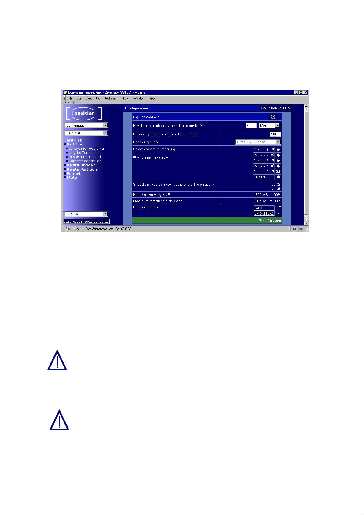
Impulse Controlled
The pulse caused by an event (refer to Chapter 9.3) triggers the recording of images
for a preset period of time.
Figure 50: Setting up an impulse controlled partition
1. Set the recording time of an event. You can select "Seconds" or "Minutes".
2. Specify the number of events to be stored.
3. Select the recording speed from "25 Images / 1 Second" to "1 Image / hour (3600
Seconds)".
4. Select the camera for recording. The connected cameras are identified by a
camera icon.
5. Now specify whether the recording is to be stopped once the maximum number of
images has been reached, or whether it is to be continued at the beginning of the
partition.
If the recording is continued once the maximum number of images has been
reached, the images already recorded will be overwritten!
6. Click the "Add Partition" button to accept the configured partition data. The
storage space required for the settings selected will automatically be displayed in
real terms and as a percentage along with the remaining storage space.
Since the last partition can never be bigger than the available hard disk
space, the percentage figure can only show the maximum amount of
memory available.
The recordings are started when an event occurs and stopped according to your
settings.
)
Note: If an event occurs while a recording is in progress, the recording related to
the second event is started directly after the first recording is terminated.
Manual - 75 -

Contact Controlled
The recording of the images continues for as long as an event input of the Convision
V6xx A is activated. For example, recording continues whilst there is movement in
the range of the motion detector. Since there is no possibility of determining the
lengths of the individual recording sessions, you cannot define the number of events
that are to be stored. For this reason, you have to define the size of the entire
partition.
Figure 51: Setting up a contact-controlled partition
1. Specify the total recording length of the partition. You can select "Seconds" or
"Minutes".
2. Select the recording speed from "25 Images / 1 Second" to "1 Image / hour (3600
Seconds)".
3. Select the camera for recording. The connected cameras are identified by a
camera icon.
4. Click the "Add Partition" button to accept the configured partition data. The
storage space required for the settings selected will automatically be displayed in
real terms and as a percentage along with the remaining storage space.
Since the last partition can never be bigger than the available hard disk
space, the percentage figure can only show the maximum amount of
memory available.
The recording sessions are started and stopped by events.
- 76 - Convision V600 A Series

9.5.2 Deleting Images on Individual Partitions
On this page you can completely and irrevocably delete all the images stored on the
corresponding partition by clicking the "Delete images” button.
)
Note: It is not possible to delete individual images. You cannot delete images
during a recording session.
9.5.3 Delete Partition
Figure 52: Page for deleting individual partitions
In this menu you can completely and irrevocably delete the last partition set up. All
the existing partitions with their set parameters, the total hard-disk space used and
the remaining free disk space will be displayed. If you want to delete all the partitions,
it is advisable to format the hard disk (refer to Chapter 9.5.4).
)
Note: You cannot delete the partition while recording.
9.5.4 Format
Figure 53: Format menu
Manual - 77 -

In the "Format" menu you can delete all the partitions from the hard disk. You can
then set up new partitions in the "Partition" menu.
During the formatting process, all the data will be deleted from the hard disk.
The system report (system.log) will also be deleted.
9.5.5 State – Information on the Hard Disk Partitioning
Figure 54: Hard disk status
This menu displays up-to-date information on your hard disk. This consists of:
♦ total storage capacity of the hard disk
♦ number of partitions set up
♦ remaining free disk space
Information on the individual partitions is displayed below these general data. This
consists of:
♦ type of partition (refer to Chapter 9.5.1)
♦ cameras selected
♦ maximum number of images/events that can be stored on the partition
♦ number of images/events already recorded
♦ Continuous recording – specifies whether the recording is terminated or continued
at the beginning of the partition once the maximum number of images has been
reached.
♦ recording speed at which the images are stored on the partition
♦ the indicator in the bottom right-hand corner shows whether a recording is in
progress or not
black indicator recording not in progress
red indicator recording in progress
- 78 - Convision V600 A Series

9.5.6 System Report – Event Log Display on the Hard Disk
All events are displayed on the internal hard disk in a 5 MB storage area. Whilst the
HTML “event log” is deleted once the device is turned off, the system report
(system.log) will still be saved when the device is turned on again.
The report can be accessed via FTP. If the configuration section has been protected,
you will need to enter the admin log-in and password.
ftp://admin:<adminpassword>@<IP-address>/log
The FTP server function must be activated to allow FTP access.
If the hard disk is reformatted, the system report will be deleted!
Manual - 79 -

10 General Descriptions
10.1 Using the Convision V6xx A as a Video
Server
If the Convision V6xx A is integrated in your LAN with a fixed IP address, it can be
accessed as a web server directly from the Internet . However, do bear in mind that
the capacity of the video server is limited – with a large number of users, a proxy
server solution is strongly recommended (CGI script and daemon on a more powerful
web server).
A great advantage of this connection option are the high image refresh rates.
10.2 Live optimized and Live compatible
There are three options for displaying frame sequences (Motion-JPEG) in your
browser:
Live optimized - Server Push is a software program executed in the browser for
continuously playing back images without the connection between the server and
browser being interrupted. It is available in Netscape Navigator only.
Live optimized - Convision Systems developed an ActiveX plugin especially for
displaying frame sequences in Internet Explorer. When starting the first frame
sequence using this program, it will be installed as a plugin for the Internet Explorer
on your computer.
Live compatible - A Java applet also developed by Convision Systems GmbH is
available for this and all the other browsers.
10.3 FTP
For transmitting images via FTP (File Transfer Protocol), the Convision V6xx A can
be used either as an FTP server or as an FTP client. It is always the client that takes
the initiative for transferring data.
As a server, the Convision responds to the request of a client, e.g. the browser, and
sends the requested images (FTP download). As a client, the Convision V6xx A dials
up a server and transmits one or more pre-configured images. An FTP upload is
performed.
10.4 Password Encryption
Some providers use the encrypted submission of the registered password as an
additional security feature. If you have defined a password for incoming or outgoing
connections on the Convision V6xx A, you can activate the password encryption
function.
If the provider does not accept the encrypted transfer of the password, the
connection will still be established via the unencrypted transfer of the password.
- 80 - Convision V600 A Series

If you did not define a password, this option will be ignored.
Ask your provider whether password encryption is supported or not.
10.5 Channel Bundling
An basic ISDN access provides two transmission channels with a bandwidth of 64
kbit each for language or other user data. These channels are referred to as Bchannels. For a standard ISDN connection, only one of the two available B channels
is used. When both the B-channels are used for data transfer, this is referred to as
"channel bundling". This means, twice the data volume can be transferred at the
same time. The charges accrue per channel, which means that they will be doubled
during channel bundling.
Channel bundling can be activated individually for incoming and outgoing
connections to the Convision V6xx A.
Not all providers support this option. If you activated channel bundling but your
provider does not support this option, a single channel connection will be established.
Ask your provider whether channel bundling is supported or not.
)
Note: If your provider does support channel bundling but it is not possible to
bundle the two lines, the connection will be terminated with an error message in the
status display (refer to Chapter 9.1.12).
10.6 SMTP or Mail Server
An SMTP (Simple Mail Transfer Protocol) server forwards outgoing e-mail messages
to the recipient. The address of the SMTP server can be obtained from the system
administrator for a LAN connection and from your telecommunications provider for an
ISDN connection.
To be able to access the SMTP server, the e-mail address of the sending Convision
V6xx A must be registered with the provider.
SMTP Authentication – SMTP-after-POP
Some e-mail providers require authentication to prevent anyone with an unauthorised
or fake e-mail address from using the SMTP server. One authentication method is
SMTP Authentication. You need to enter a user name and password for this.
Another authentication is a registration via POP 3 (Post Office Protocol – Protocol
used to access a server which stores e-mails for other computers).
If the provider requires this method for authentication, just enter the user names and
password in the same way you have to to receive your e-mail.
10.7 Control via CGI Parameters
CGI (Common Gateway Interface) is a way of providing programs that can be
opened by HTML files. The program and the parameters to be used to open the
program are placed in the URL following the IP address. An example is given below:
Manual - 81 -

http://IP_address/path/CGI program?Parameter1=value1&Param2=value2&...
This program with its parameters can be opened using a button, a link, a form or the
address line of a web page. CGI programs are used by the Convision Call service,
for example, or for controlling non-supported devices via the serial URL port.
For more information on this topic, please refer to the Convision Programmer
Manual, which can be downloaded free of charge at
www.convision.de.
10.8 TCP/IP and IP Addresses
TCP/IP is a group of protocols with the TCP (Transmission Control Protocol) and IP
(Internet Protocol) being the group's most important components. They form the
widest spread solution in the area of internetworking and have established a de facto
market standard.
Internet addresses are used to identify computers in TCP/IP networks. They are part
of the Internet Protocol and are therefore referred to as IP addresses.
The Structure of an IP Address
An IP address consists of four numbers between 0 and 255, separated by dots, e.g.
192.168.0.53. Every IP address is made up of 2 parts. The first numbers define the
network identification (network ID) the last define the device (host ID). The length of
each part is defined by the network mask. (see below).
To integrate a device into your local area network properly, you have to assign an IP
address to the device.
Every device needs its own IP address.
The Domain Name Service (DNS)
The domain name service enables the assignment of a name to each computer in a
TCP/IP network. The fundamental component of the DNS is a database that is
managed by a name server. These name servers can be either public or part of a
private network. Example:
Assuming a computer has the IP address 212.68.72.16
It has the assigned name "Computer.organization.de". This is a name for any
computer in any company located in Germany.
If you enter “http//: Computer.organization.de" in the address line of your browser a
connection to computer “212.68.72.16” will be established.
If a DNS server is not available in your LAN, use a text file that maps the names of
the individual computers to the associated IP addresses.
- 82 - Convision V600 A Series

)
Note: This file named Hosts is stored in the Windows directory (Windows 98), in
the WINNT directory (Windows NT) or as /etc/hosts under Unix.
The Network Mask
The network mask is used to determine which part of the IP address describes the
network and which part identifies the computer in the network. Example:
Assuming the IP address of a computer is 192.168.100.3
And assuming the net mask is 255.255.255.0.
Then the network identification is 192.168.100. The fourth number (3) identifies the
computer.
)
Note: Incorrectly defined IP addresses and network masks very often cause
errors in TCP/IP networks. For this reason, if you are not absolutely sure or if
problems come up, please contact an experienced network administrator.
Manual - 83 -

11 Technical Data
Camera inputs 6 FBAS inputs, PAL, NTSC, BNC connectors (female)
Interfaces 2 x RS232 (serial), D-Sub9 connectors (female)
Detector inputs 6 NC inputs for motion detectors etc.,
1 x key-operated switch
Alarm outputs 1 x open collector (100 mA), 1 x 12 V/500 mA switching
output
Hard disk drive Convision V610 A: min. 20 Gbyte
Convision V610 A XXL: min. 40 Gbyte
Transmission ISDN, LAN 10 Base T, Modem, GSM optional
Audio Function Via the second ISDN B-channel, door intercom system,
e.g. TLE051-01 by Siedle
Dome support e.g. Sony EVI-D30/D31, Sensormatic SpeedDome, Philips
G3 AutoDome, Ernitec BDR510/550, Dennard 2050 (>=
V4.0 Build 1883), JVC TK-C675B, Lilin PIH-7000 Series,
Panasonic WV-CS850 Series, SAE Dragon, Canon VCC4/C4R, VCL Microspere Orbiter Gold, Vicon Surveyor 99
und 2000-16/22, Pelco Spectra II and III (D protocol),
Honeywell HSD-251P, Samsung SCC-641 (Vicon
protocol)
Alarm center support The VdS 2465 protocol is supported.
Compression JPEG, up to 25 frames/second (PAL), up to 30
frames/second (NTSC)
Approx. 3-50 KB/frame
Frame size Resolution of 192x144, 384x288, 768x288 (with
Pixelzoom 768x576) pixels
Pre / post alarm frames 32 frames with a resolution of 192 x 144 pixels or 16
frames with a resolution of 384x288 pixels
Activity Detection 1 camera
Recording capacity Convision V610: 1 camera: 25 frames/s
2 cameras in parallel: 2 frames/s
3 cameras in parallel: 1 frame/s
Protocols TCP/IP, HTTP, FTP, SMTP Client
Configuration Completely with a Web browser via HTML
Internet Browser e.g. Netscape Navigator 4.x or higher, Microsoft Internet
Explorer 5.5 or higher
HTTP 1.0 and HTML 3.2, Java Script 1.2, Java 1.4
Power supply External 12 V/1.5 A multi-standard power pack 100 - 240
V (GS, CE, UL, CSA)
Power consumption Convision V600 A: 6W
Convision V610 A: 10W
Dimensions Width: 163 mm, height: 80 mm, depth: 185 mm
- 84 - Convision V600 A Series

Weight Convision V600 A: 1,295g
Convision V610 A: 1,435g
Temperature range 0 °C to +55 °C (+32 °F to +131 °F)
Approvals EN50081, EN 50082, EN 55022, CE0682
Manual - 85 -

Appendix A Declaration of
Conformity
KONFORMITÄTSERKLÄRUNG
DECLARATION OF CONFORMITY
Geräteart: Micro Web Server
Type of equipment:
Produkt / Product : Convision V600 A Series
Das bezeichnete Produkt stimmt mit den Vorschriften folgender EU- Richtlinie(n)
überein:
The aforementioned product complies with the following European Council directive(s):
93/97/EWG EG EMV- Richtlinie / EC EMC directive
1999/5/EG EG Telekommunikationsendeinrichtungen - Richtlinie
EC Telecommunications terminal equipment directive
Zur vollständigen Einhaltung der EMV- Richtlinie wurden folgende Normen
herangezogen:
To fully comply with the EMC directive, the following standards have been used:
EN 55022 Class B : 1987
EN 50081-1 : 1995
EN 50082-2 : 1995
Dieser Erklärung liegt zugrunde: Prüfungen im EMV- Prüflabor
This certification is based on: Tests in EMI test laboratory
Aussteller / Holder of certificate : Convision Systems GmbH
Zuckerbergweg 22
38124 Braunschweig
Germany
- 86 - Convision V600 A Series

Appendix B List of Figures
Front view of the Convision V6xx A 9
Rear view of the Convision V6xx A 10
LAN connection 11
Connection via ISDN 12
Camera connections 14
Key-operated switch 15
Example of the input connections 16
Example of an OC output connection 16
Example of an alarm output connection 17
Initial configuration using Convision IPSetup 19
Camera display 23
View of a fully controllable camera 24
Playback 28
List of Events 29
Menu for manual recording 30
Displaying the images in the frame buffer 31
Configuring the outputs 32
Configuring the IP addresses 34
Configuring the mail server 36
Configuring the ISDN parameters 37
Configuring connections 39
Audio connections 41
Audio data transmission 41
Configuring the Convision Call server 43
Configuring Convision Call in the Convision V6xx A 43
Selecting the language 45
Update dialog box 48
The three security levels 49
FTP-Server dialog box 51
Assignments of the serial ports 52
Event log 53
Gerneral camera settings 54
Setting the camera properties 1 55
Setting the camera properties 2 56
Configuring the alarm inputs 57
Configuring the inputs – weekly schedule 58
Configuring the points in time – assigning actions 59
Configuring the points in time – weekly schedule 59
Configuring the time periods – assigning actions 60
Configuring the periods – weekly schedule 61
Configuring the activity detection 62
Activity Detection – properties 63
Configuring the frame buffers 64
FTP upload 66
Configuring e-mail notification 68
Manual - 87 -

Configuring SMS 69
Configuring VdS2465 70
Setting up a long-time recording partition 72
Setting up a ring buffer partition 73
Setting up an impulse controlled partition 75
Setting up a contact-controlled partition 76
Page for deleting individual partitions 77
Format menu 77
Hard disk status 78
- 88 - Convision V600 A Series

Appendix C List of Keywords
Events...................................................................56
A
Action....................................................................64
ActiveX..................................................................22
Activity Detection.......................................57, 62, 70
Administrator.........................................................34
Administrator password .........................................49
Alarm center..........................................................44
Applet.............................................................. 33, 46
Audio...............................................................10, 40
Authentication ...........................................36, 39, 81
FBAS cameras......................................................10
Firmware.........................................................20, 48
Formatting the hard disk .......................................78
FPS.......................................................................23
Frame Buffer.................................30, 49, 56, 64, 67
FTP.......................................................................80
Client.................................................................66
Server..........................................................50, 79
F
B
Battery...................................................................50
B-channel..................................................40, 42, 81
C
Cabling
cross-connect....................................................12
Camera
connection.........................................................13
controllable......................................14, 24, 52, 55
properties ..........................................................55
Camera Tour...................................................56, 70
Camera used.........................................................62
CGI Parameters ..............................................53, 81
Channel bundling ..................................................81
Configuration
Convision Call ................................................... 42
Main ..................................................................34
Modem ..............................................................40
Configuration file ...................................................47
Configuring
Hard disk...........................................................71
Connection
of the Convision V6xx to the provider................38
via ISDN............................................................ 36
Connectors........................................................9, 10
Convision Call .......................................................42
Cross-connect cable..............................................18
Cross-connect cabling...........................................19
H
Hard disk...............................................7, 51, 64, 71
HD Level ...............................................................62
Host identification..................................................82
HTML pages....................................................21, 33
Hue .......................................................................55
I
Image sequence....................................................29
Image size.......................................................22, 51
Image stream........................................................55
Indicator lamps........................................................9
Information............................................................33
Initial configuration..........................................18, 19
Inputs ........................................................15, 56, 57
Internet Browser....................................................18
IP address.....................................19, 20, 34, 36, 82
IPSetup .................................................................19
Iris.........................................................................25
ISDN ...................................................10, 18, 36, 42
ISDN basic access..................................................8
J
Java Applet ...........................................................54
Java Virtual Machine...............................................8
JPEG.....................................................................22
K
D
Delete
Configuration.....................................................20
Images ..............................................................77
Partition.............................................................77
Devices .................................................................52
Dial-up networking...........................................18, 37
DNS server............................................................35
Domain Name Service (DNS)..............34, 36, 39, 82
Door intercom system ........................................... 40
Key-operated switch........................................15, 58
L
LAN.................................................................11, 19
Language........................................................21, 45
Language module .................................................45
LED...................................................................9, 15
Live Video Loss.....................................................61
Live-compatible.............................22, 23, 27, 63, 80
Live-optimized.....................................22, 27, 63, 80
Log........................................................................79
E
E-Mail..............................................................67, 69
eMail State ............................................................69
Ethernet...........................................................10, 19
Event log...............................................................53
Mail Server............................................................35
Microsoft Internet Explorer..............................22, 63
Manual - 89 -
M

Modem...................................................... 13, 37, 40
Module............................................................33, 46
Movement.............................................................63
MSN................................................................18, 40
Multiple subscriber number (MSN) .................18, 37
N
Netscape-Browser..................................................8
Network identification............................................ 82
Network mask....................................................... 83
Network terminator (NT) .......................................12
O
Open collector output...................................... 16, 32
Output........................................... 17, 23, 32, 56, 65
P
Panoramic view ....................................................25
Partition
Delete ............................................................... 77
Type
Contact controlled.........................................76
Impulse controlled......................................... 75
Long-time recording......................................72
Ring buffer....................................................73
Password..............................................................42
Password encryption ............................................80
Play.......................................................................27
Playback speeds...................................................28
Plugin.................................................................... 22
Port....................................................................... 35
PPP ..........................................................18, 37, 38
PPP Host Name....................................................37
Preset ....................................................... 24, 25, 56
Preset Tour...........................................................26
Serial interfaces....................................................52
Serial number
of the Convision V6xx....................................... 33
Serial URL port..................................................... 52
Server Push..........................................................80
SMS (Short Message Service) .............................69
SMTP.................................................................... 81
Snapshot ........................................................23, 24
Sockets
controllable ....................................................... 32
Speed...................................................................71
State
Frame Buffer..................................................... 31
Hard Disk..........................................................78
Summer Time....................................................... 50
Syslog-Server....................................................... 35
System Report......................................................79
System settings.................................................... 34
T
TCP/IP............................................................ 82, 83
Time................................................................50, 59
Time Period .......................................................... 60
Time zone.............................................................50
Tour.................................................... 24, 26, 56, 70
TP cable ...........................................................8, 11
U
Updating the firmware...........................................48
Upload
Applet ...............................................................46
Configuration file............................................... 47
FTP............................................................. 38, 66
Language.......................................................... 45
Module..............................................................46
URL ...................................................................... 53
User password................................................ 37, 50
Q
Quad view............................................................. 21
R
Record..................................................................30
Reset ......................................................................9
Router...................................................................35
S
Safety Instructions..................................................6
Security settings ................................................... 49
Sequencer ............................................................ 26
V
VdS 2465........................................................44, 70
Video Loop output................................................. 62
View of two cameras.............................................22
W
Weather station.....................................................33
Z
Zoom .................................................................... 25
- 90 - Convision V600 A Series
 Loading...