

Convision V600 A, V610 A, V610 A XL, V610 A XXL User Manual

Convision V600 A Series
User Manual
Version 5.1
November 2003
© Convision Systems GmbH
All rights reserved
No part of this manual may be reproduced or transmitted in any form without the prior
written permission of Convision Systems GmbH.
All the information and descriptions have been compiled with great care on the basis
of thorough research. Despite our great care, we cannot completely rule out errors or
altered applications that may lead to changed operational sequences or different
results. Convision Systems GmbH can accept neither legal responsibility nor any
other liability for any consequences arising from this or from unintentional errors.
Convision und Convision V600 A Series are trademarks of Convision Systems
GmbH.
Microsoft® and MS-Internet Explorer® are trademarks or registered trademarks of
Microsoft Corporation. Netscape® and Netscape Navigator® are registered
trademarks of Netscape Communications Corporation. Any other trade names and
product names are the trademarks or registered trademarks of the respective
owners.
Convision Systems GmbH cannot accept liability for increased call charges, including
costs arising from accidental connection setup.
Convision Systems GmbH has created this manual to the best of its ability but cannot
guarantee that the programs / systems will serve the purpose aspired by the user.
Convision Systems GmbH reserves the right to modify the content of the User
Manual without accepting the obligation of informing third parties.
We reserve the right to make technical modifications.
- 1 -

General
Congratulations on purchasing a unit of the Convision V600 A Series.
The Convision V600 A Series is available in the following versions:
♦ Convision V600 A
♦ Convision V610 A Convision V610 A XL Convision V610 A XXL
Many of the descriptions and instructions contained in this manual apply to all the
versions. In this case, the name "Convision V6xx A" is used.
This manual intends to convey the knowledge required to connect and handle your
Convision V6xx A. General information on configuring the required software on your
computer you will find in the “Convision System Configuration“document. You do not
need any special software to operate the Convision V6xx A since all the components
are generally included in the standard software package supplied with the computer.
Please read this manual before connecting your Convision V6xx A.
You can download the latest update of the Convision V6xx A manual and the
Convision V6xx A firmware free of charge from the Convision Website
(
www.convision.de).
Operate the Convision V6xx A exclusively with 12 V DC.
Step by Step Procedures
1. Meeting the System Requirements – refer to Chapter 3
2. Connecting the Components – refer to Chapter 5
3. Configuring the System – refer to document “Convision System Configuration“
4. Setting up Your Browser – refer to document “Convision System Configuration“
5. Configuring Your Convision V6xx A – refer to Chapter 6 and 9
- 2 - Convision V600 A Series

Contents
1 General Information .....................................................6
1.1 Scope of Delivery.......................................................................... 6
1.2 Safety Instructions.......................................................................6
2 Product Variations........................................................7
2.1 Convision V600 A.......................................................................... 7
2.2 Convision V610 A.......................................................................... 7
3 System Requirements...................................................8
3.1 Requirements for Operation in an ISDN Telephone Network ........ 8
3.2 Requirements for Operation in a Local Area Network (LAN).........8
3.3 Software Requirements................................................................ 8
4 Controls, Connectors and Indicators.............................9
4.1 Front View....................................................................................9
4.2 Rear View................................................................................... 10
5 Connecting the Convision V600 A Series.....................11
5.1 Connecting the Unit to the Power Supply ...................................11
5.2 Connecting the Unit to the LAN................................................... 11
5.3 Connecting the Unit to the ISDN.................................................12
5.4 Connecting the Unit via Modem ..................................................13
5.5 Connecting the Cameras............................................................. 13
5.6 The Key-Operated Switch ...........................................................15
5.7 Input and Output Connections.................................................... 15
5.7.1 Example: Input Connections .......................................................... 15
5.7.2 Example: Open Collector Output Connection..................................... 16
5.7.3 Example: Alarm Output Connection................................................. 17
6 Initial Configuration of the Convision V6xx A .............18
6.1 MSN Configuration via ISDN....................................................... 18
6.2 IP Configuration in a Local Area Network................................... 19
6.3 IP Configuration via a Direct Connection Using a Cross-Connect
Cable .......................................................................................... 19
6.4 Deleting the Configuration.......................................................... 20
7 The HTML Pages – Operation and Configuration .........21
8 Operation....................................................................22
8.1 Cameras ..................................................................................... 22
8.1.1 Controllable Camera ..................................................................... 24
8.1.2 Sequencer................................................................................... 26
8.2 Playback (Convision V610 A only) ..............................................27
8.3 Recording (Convision V610 A only) ............................................ 30
8.4 Frame Buffer Display.................................................................. 30
Manual - 3 -

8.5 Applications................................................................................ 32
8.5.1 Activating Outputs Manually............................................................32
8.5.2 Sockets .......................................................................................32
8.5.3 Weather Station............................................................................33
8.6 Applets....................................................................................... 33
8.7 Modules...................................................................................... 33
8.8 Information................................................................................ 33
9 Configuration ............................................................. 34
9.1 System Settings ......................................................................... 34
9.1.1 LAN/Ethernet Connection Data........................................................34
9.1.2 ISDN/Modem Connection Data ........................................................36
9.1.3 Language.....................................................................................45
9.1.4 Applets........................................................................................46
9.1.5 Modules.......................................................................................46
9.1.6 Configuration – Saving and Uploading..............................................47
9.1.7 Update – Uploading New Firmware ..................................................48
9.1.8 Security Settings...........................................................................49
9.1.9 Setting the Time and Date..............................................................50
9.1.10 Activating the FTP Server ...............................................................50
9.1.11 Assignment of Devices to the Serial Ports .........................................52
9.1.12 Event Log.....................................................................................53
9.2 Camera Settings ......................................................................... 54
9.2.1 General – Settings for the Image Display..........................................54
9.2.2 Name – Renaming Cameras............................................................54
9.2.3 Pan/Tilt........................................................................................55
9.2.4 Setting the Camera Properties.........................................................55
9.3 Events – Actions When an Alarm Is Triggered............................ 56
9.3.1 Inputs .........................................................................................57
9.3.2 Key Switch...................................................................................58
9.3.3 Time Control – Time-Dependent Actions...........................................59
9.3.4 Time Period..................................................................................60
9.3.5 Live Video Loss .............................................................................61
9.3.6 Camera used................................................................................62
9.3.7 HD Level (Convision V610 A only)....................................................62
9.3.8 Activity Detection..........................................................................62
9.4 Actions ....................................................................................... 64
9.4.1 Hard Disk – Configuring the Hard Disk .............................................64
9.4.2 Configuring the Frame Buffers.........................................................64
9.4.3 Output (Time)...............................................................................65
9.4.4 Transferring Data via FTP (Upload) ..................................................66
9.4.5 Notification via E-Mail ....................................................................67
9.4.6 E-Mail State (eMail State)...............................................................69
9.4.7 Notification via SMS (Short Message Service)....................................69
9.4.8 VdS 2465.....................................................................................70
9.4.9 Further action with no configuration page .........................................70
9.5 Configuring the Hard Disk (Convision V610 A only).................... 71
9.5.1 Partitioning the Hard Disk...............................................................71
9.5.2 Deleting Images on Individual Partitions...........................................77
9.5.3 Delete Partition.............................................................................77
9.5.4 Format ........................................................................................77
9.5.5 State – Information on the Hard Disk Partitioning ..............................78
- 4 - Convision V600 A Series

9.5.6 System Report – Event Log Display on the Hard Disk......................... 79
10 General Descriptions...................................................80
10.1 Using the Convision V6xx A as a Video Server............................ 80
10.2 Live optimized and Live compatible............................................80
10.3 FTP .............................................................................................80
10.4 Password Encryption .................................................................. 80
10.5 Channel Bundling ....................................................................... 81
10.6 SMTP or Mail Server.................................................................... 81
10.7 Control via CGI Parameters ........................................................81
10.8 TCP/IP and IP Addresses ...........................................................82
11 Technical Data ............................................................84
Appendix A Declaration of Conformity ..................................86
Appendix B List of Figures ....................................................87
Appendix C List of Keywords.................................................89
Manual - 5 -
1 General Information
1.1 Scope of Delivery
After unpacking, make sure that all the parts have been delivered.
Convision V6xx A
Power pack DC 12 V/1.5 A
Power cable
ISDN cable
CD-ROM with Convision IPSetup tool
Manual
The device type and the serial number are on an adhesive label underneath the
Convision V6xx A. This information is also included in the manual and on the HTML
pages in the "Information" menu (refer to chapter 8.8). In the "Information" menu, you
can also check the current software version of your Convision V6xx A.
1.2 Safety Instructions
The Convision V6xx A is a high-quality electronic product. Please follow the safety
instructions below to prevent damage:
Never place the Convision V6xx A near a heating source e.g. furnace
or heaters or expose it to direct sunlight.
Do not cover the Convision V6xx A.
Only clean Convision V6xx A using a moist cloth only without
abrasive cleaning agents and install your Convision V6xx A where it
is protected against splash water.
Never open the Convision V6xx A yourself. In the event of a
malfunctions or defects, please contact the Convision Systems
- 6 - Convision V600 A Series
GmbH support service or your dealer.
Opening the unit invalidates the warranty!

2 Product Variations
2.1 Convision V600 A
As many as 6 cameras with PAL/NTSC composite signal can be connected to the
basic device of the Convision V600 Series, the Convision V600 A – a CCTV (Closed
Circuit Television) Web server. The video data are transmitted either via TCP/IP in a
local network, via a single or dual ISDN channel or via an analog modem.
There are 6 alarm event inputs for surveillance functions and two outputs for the
direct control of the alarm devices. Additional devices such as pan/tilt cameras or
cameras with zoom functions can be controlled via the serial interfaces.
In the integrated services digital network (ISDN), it is possible to transmit audio data
parallel to the image data on the second B-channel.
Other devices of this series are available that are equipped with all the basic
functions of the Convision V600 A and offer various additional features.
All the variants have an identical basic configuration.
2.2 Convision V610 A
This variant of the Convision V600 A is equipped with a 2.5" hard disk for long-time
recording.
Versions: Convision V610 A with a HDD of at least 20 GB
Convision V610 A XXL with a HDD of at least 40 GB
The internal notebook hard disk ensures a recording time of 9 hours per GB of hard
disk space at 1 frame per second (resolution 384 x 288, frame size 32 KB).
With a resolution of 192 x 144 (8 KB) it is possible to record up to 36 hours per GB of
hard disk space at the same recording speed.
Before taking the Convision V 610 A into operation, it must be configured in the same
way as the Convision V600 A (setting the IP address etc.).
Please refer to Chapter 8 for more information on the recording and playback
functions.
Manual - 7 -

3 System Requirements
3.1 Requirements for Operation in an ISDN Telephone Network
For configuring and operating the Convision V6xx A via ISDN, you need an basic
ISDN access.
The Convision V6xx A is completely ready for connection via ISDN, which means the
user need not perform any installation works. The Convision V6xx A has been
equipped with an ISDN card and the required ISDN software has been installed. For
configuring the connections that are to be established via the ISDN interface, please
refer to document “Convision System Configuration“.
If you want to make further settings for the Convision V6xx A (e.g. TCP/IP, camera
settings etc. ) via the ISDN interface, you need a computer with ISDN capabilities.
For more information, please refer to Chapter 6.1.
3.2 Requirements for Operation in a Local Area Network (LAN)
For installing the Convision V6xx A in a LAN, you need a computer with an Ethernet
interface. The Convision V6xx A requires a 10 Mbit twisted pair (TP) connection.
For detailed information on cabling, please refer to Chapter 5.2.
3.3 Software Requirements
To be able to configure the Convision V6xx A, you need an Internet browser that
supports Java such as Microsoft Internet Explorer 5.5 or Netscape Navigator 4.x.
You do not need any special software to operate the Convision V6xx A since all the
components are generally included in the standard software package supplied with
the computer.
On computers with an MS operating system, you can configure the system by using
Convision IPSetup directly in the form of an .exe file. In the case of other operating
systems, you have to install a "JVM" (Java Virtual Machine), if not yet installed.
- 8 - Convision V600 A Series
4 Controls, Connectors and
Indicators
The Convision V6xx A is equipped with various controls, connectors and indicator
lamps (LEDs). These are described below.
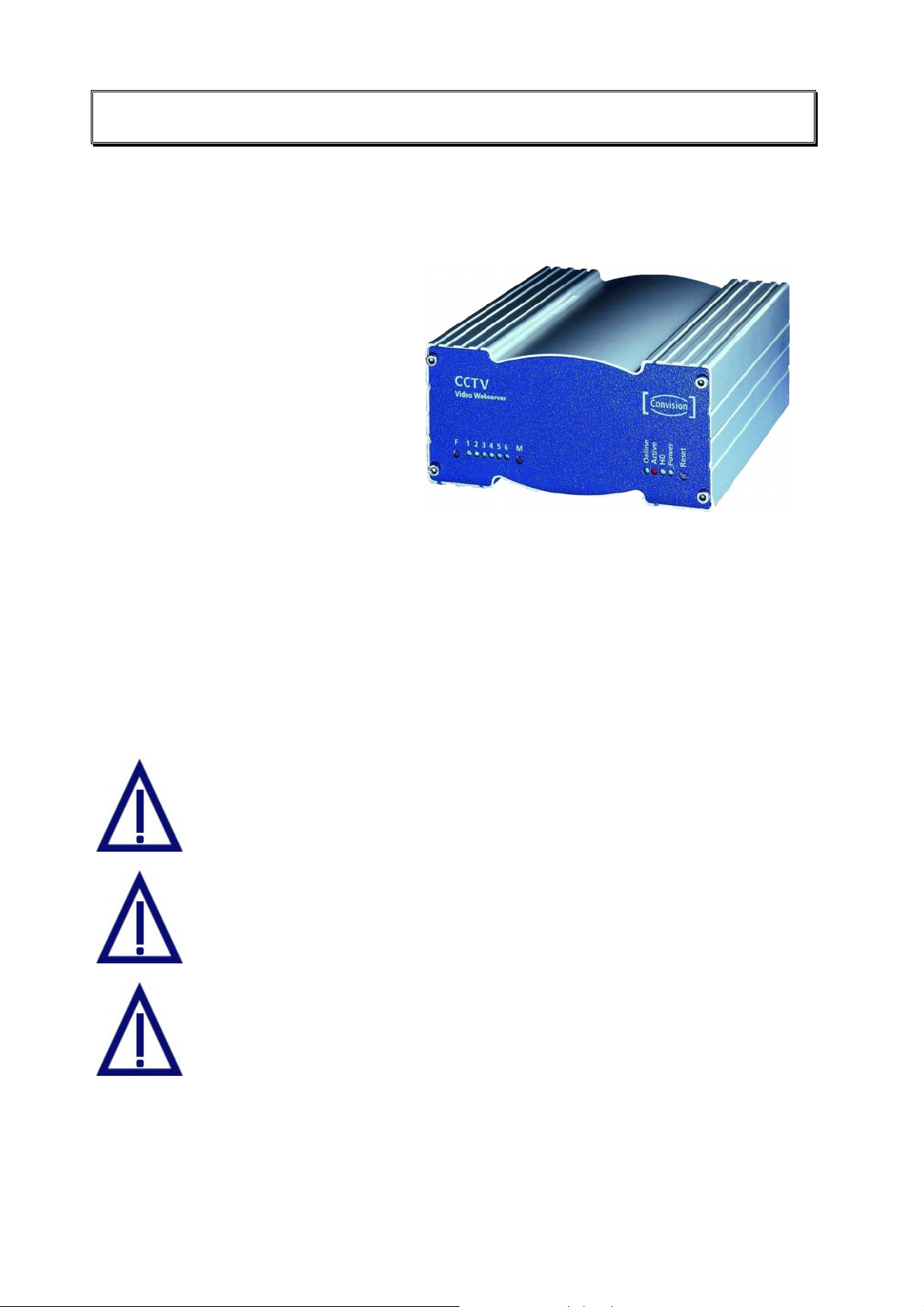
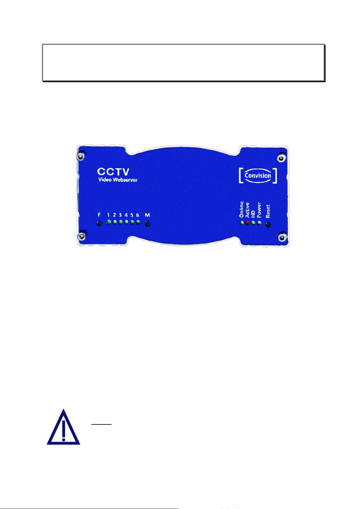
4.1 Front View
Figure 1: Front view of the Convision V6xx A
♦ F button: deletes the hard disk.
♦ LEDs 1-6: these light up when a camera is connected to the corresponding port;
they flash when the respective camera is being accessed.
♦ M button: deletes the configuration.
♦ Online LED: is lit when the Convision V6xx A proactively established a
connection.
♦ Active LED: is lit when the alarm function of the Convision V6xx A has been
switched to "alert".
♦ HD LED : (HD = hard disk); is lit when data is written to or read from the hard disk
(option).
♦ Power LED: lights up as soon as the Convision V6xx A is connected to the power
supply and switched on.
♦ Reset button: when this button is activated, the Convision V6xx A is reset. This
means the Convision V6xx A is rebooted and re-initialized.
Never
Convision V6xx A as this would cause the entire software to be
deleted.
press F and M together when you switch on the
Manual - 9 -

4.2 Rear View
All the external connectors are located on the rear panel of the Convision V6xx A.
Connectors of the Convision V600 A/610 A:
♦ CAM 1 ... CAM 6: You can connect six independent FBAS cameras to these
connectors.
♦ COM 1: Serial interface: is used to control external devices, e.g. a pan/tilt camera,
weather station etc.
♦ COM 2: Serial interface: is also used to control external devices. An analog
modem can be connected to this interface.
♦ Ethernet: 10 Base T connection for operating the Convision V6xx A in a LAN.
♦ ISDN: This connector is used for operating the Convision V6xx A via an ISDN
multi-device access.
♦ Audio: This is the connector for the microphone and loudspeaker of an audio
transmission device, e.g. a door intercom system.
♦ Power switch: used to switch the device on and off.
♦ Power, 12 V DC: This is the connector for the power pack supplied with the unit.
♦ I/O Connector: This connector is for additional devices, e.g. smoke and motion
detectors (refer to Chapter 5.7).
Figure 2: Rear
view of the
Convision
V6xx A
- 10 - Convision V600 A Series
5 Connecting the Convision V600 A
Series
There are three possibilities of operating the Convision V6xx A. You can operate it
either in a Local Area Network (LAN), via ISDN or an analog modem.
For initial configuration of the unit, there is an additional direct connection option.
♦ Via a cross-connect cable, refer to Chapter 6.3.
5.1 Connecting the Unit to the Power Supply
Connect the 12 V DC plug of the power pack connecting cable to the 12 V DC Power
connector (female) of your Convision V6xx A. Connect the power pack provided with
the unit to the power supply socket using the power cable. Activate the Power switch
on the rear of the unit. The Power LED will light up.
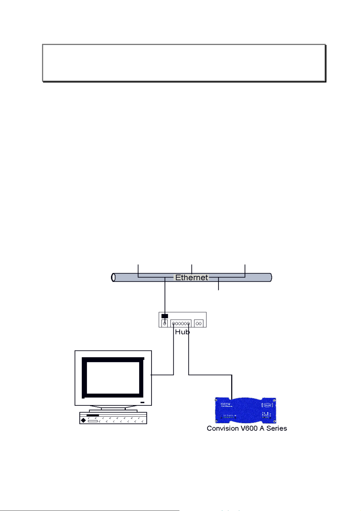
5.2 Connecting the Unit to the LAN
In a LAN, you have to establish a connection between the Convision V6xx A and
your computer via a hub or switch using a twisted-pair cable with an RJ-45
connector.
Figure 3: LAN connection
1. Connect one end of the TP cable to the Ethernet output on the rear of the
Convision V6xx A. (refer to Figure 2: Rear view of the Convision V6xx A).
Manual - 11 -
2. Connect the other end of the TP cable to one of the inputs on the hub.
3. For information on setting the IP addresses, please refer to Chapter 6.2. For
detailed information on IP addresses, please refer to Chapter 10.8.
)
Note: If you want to connect the Convision V6xx A directly to your PC, use a
cross-connect cable to connect the two devices. This is an eight-pin twisted pair
cable with crossed pin assignments (refer to Chapter 6.3).
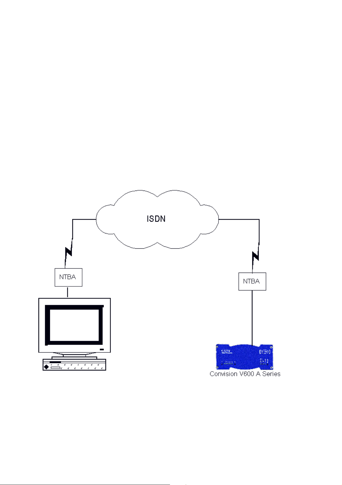
5.3 Connecting the Unit to the ISDN
Your telecommunications network operator provides ISDN access via a network
terminator (NT).
1. Plug one end of the ISDN cable provided (labeled "ISDN") into the ISDN port on
the rear of the device (refer to Figure 2: Rear view of the Convision V6xx A).
2. Plug the other end of the cable into the RJ-45-connector (female) of the ISDN
network terminator.
Figure 4: Connection via ISDN
To be able to communicate with your Convision V6xx A via ISDN, your computer
must be equipped with the appropriate ISDN hardware (e.g. ISDN card). For
information on installing ISDN hardware, please review the respective manuals of
your computer and of the device to be installed. In addition, you have to configure a
dial-up networking on your computer (refer to document “Convision System
Configuration“).
- 12 - Convision V600 A Series

Operating the Unit Connected to Telecommunications
Equipment (ISDN Telecommunications Equipment)
If you want to operate your Convision V6xx A connected to telecommunications
equipment, you have to connect the Convision V6xx A to the S
ISDN telephone that can be accessed from your computer.
For initial configuration of the unit, dial the telephone number assigned to the
telephone connected. Since this is a data call, the phone will not answer (i.e. the
phone will not ring) but the Convision V6xx A will answer the call.
-bus in parallel to an
0
) Note: In the case of telecommunications equipment it may be necessary to
enable data transmission for the access. For this purpose, contact the manufacturer
of the telecommunications equipment.
5.4 Connecting the Unit via Modem
To operate the Convision V6xx A via an analog modem, connect the modem to the
nd
2
serial interface (COM 2) of your Convision V6xx A using a serial cable. Connect
the modem to the telephone socket using the telephone cable and to the power
supply via the power pack. For information on configuring the unit, please refer to
Chapter 9.1.2.
5.5 Connecting the Cameras
Proceed as described in the following to connect one or several cameras to the
Convision V6xx A:
1. To supply the camera with 12 V DC, connect the "+" cable of the camera to the
12V DC plug, which is then connected to the 12V DC Power connector (female).
The BNC connection provides the mass connection (GND).
2. Connect the BNC connector to a camera input on the rear of the Convision
V6xx A.
Manual - 13 -
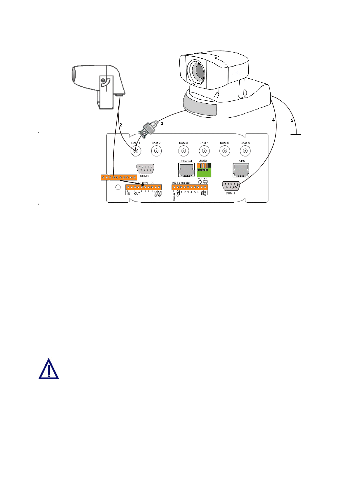
Figure 5: Camera connections
Connecting a Controllable Camera
3. Connect the video cable via the adapter supplied (Cinch on BNC) to the first
camera input on the rear of the Convision V6xx A.
4. Additionally, you have to connect the control cable (9pin Sub-D to 8pin mini DIN)
to one of the serial inputs (COM 1 or COM 2) of the Convision V6xx A.
5. The camera is supplied with power via the power pack supplied.
Define the serial input used on the Configuration / System / Device page (refer to
Chapter 9.1.11).
If you want to connect several controllable cameras to a Convision V6xx A, all the
cameras following the first one are controlled via series cable connectors of the
individual cameras (8pin mini DIN connectors). The cameras are then individually
controlled via internal port addresses.
In some controllable cameras you have to set an internal control address. For
this purpose, please use the addresses starting with "1".
For controlling a camera not supported by the Convision V6xx A you have to enable
the "Serial-URL-Port" option on the Configuration/System/Device page. For more
information on this topic, please read Chapter 9.1.11 – Serial-URL-Port. The unit is
controlled via a separate applet that can be uploaded to the Convision V6xx A (refer
to Chapter 8.6 and 9.1.4).
- 14 - Convision V600 A Series
You cannot operate 2 different types of controllable cameras simultaneously
via the Convision V6xx A.
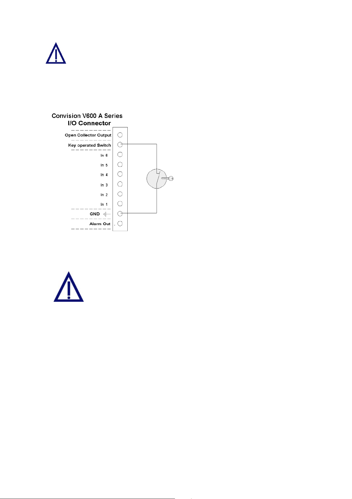
5.6 The Key-Operated Switch
The key-operated switch is connected as shown in the figure.
The key-operated switch is used to
activate the alarm function. If a keyoperated switch is not connected, the
Convision V6xx A is automatically
activated. In this case, the red "Active"
LED will be lit.
Switch unlocked Alarm function
activated
Switch locked Alarm function
deactivated
Figure 6: Key-operated switch
5.7 Input and Output Connections
Connect only devices that have been designed for 12V to your
Convision V6xx A.
Never use 230 Volts on your Convision V6xx!
5.7.1 Example: Input Connections
Alarm devices for various purposes can be connected to the six inputs. Please
observe that only 12 V devices may be connected to the inputs.
Since the inputs respond to low/high level changes, the components must be closed
in the idle state (NC type normally closed, "break contact").
Manual - 15 -
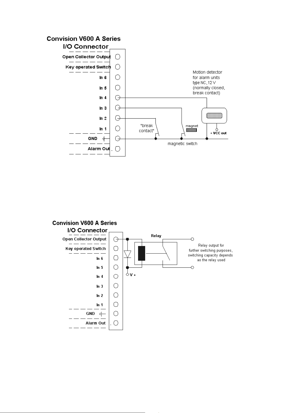
Figure 7: Example of the input connections
5.7.2 Example: Open Collector Output Connection
A relay via which higher power is then supplied, for example, can be connected to
the open collector output (OC). The breaking capacity of the OC output is
12V /100 mA.
Figure 8: Example of an OC output connection
- 16 - Convision V600 A Series
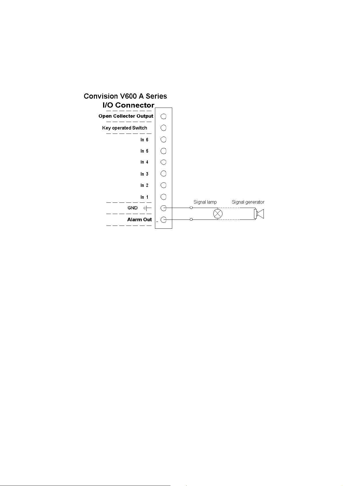
5.7.3 Example: Alarm Output Connection
An indicator lamp, for example, or any other 12 V signal device (e.g. siren), can be
connected directly to this output. The maximum load for this switching output is
12 V/500 mA.
Figure 9: Example of an alarm output connection
Manual - 17 -

6 Initial Configuration of the
Convision V6xx A
For information on the local configuration of your computer and on setting up the
browser, please refer to document “Convision System Configuration“.
To establish the first connection with the Convision V6xx A, please follow the
configuration procedure in this chapter. If you have already succeeded in establishing
a connection with the Convision V6xx A, you can skip this chapter. To customize the
configuration of your Convision V6xx A, refer to the detailed description of the
configuration options in Chapter 8.8. There, you will find a description of the menus
and buttons together with their functions.
When delivered, the Convision V6xx A is not configured, i.e. it has not been assigned
an IP address or MSN (multiple subscriber number). This is indicated by the slowly
flashing Online LED following the booting procedure. For this reason, the unit must
be configured . The configuration software "IPSetup" is on the "Products + Partners"
CD in the "Software" folder.
There are three different ways to set up the Convision V6xx A depending on your
connection.
1. MSN configuration via ISDN
2. IP configuration in a local area network
3. IP configuration via a direct link between the PC and the Convision V6xx A using
a cross-connect cable
6.1 MSN Configuration via ISDN
To set up the Convision V6xx A via ISDN, you have to install a dial-up networking on
your computer. For information on this topic, refer to document “Convision System
Configuration“.
Once dial-up networking has been configured for establishing a connection to the
Convision V6xx A, you can set up the unit. To connect to the Convision V6xx A,
establish a dial-up connection. Do not enter a username or password (refer to PPP
Password, Chapter 9.1.2) and click the "Connect" button. The ISDN connection to the
Convision V6xx A will be established.
For operation via ISDN, the IP address 10.0.0.10 has been preset for your Convision
V6xx A but you can change it.
1. Start your browser and enter
display the homepage of the Convision V6xx A.
2. Click the "Configuration", "Connections" and "ISDN/Modem" buttons one after the
other.
3. Enter the multiple subscriber number (MSN) assigned.
- 18 - Convision V600 A Series
http://10.0.0.10 as the URL. Your browser will
4. If defined, enter the PPP password to prevent unauthorized connection setup.
5. Save the data.
If you operate more than one piece of ISDN equipment on one ISDN
connection, you have to assign each unit a separate MSN number to prevent
conflicts.
6.2 IP Configuration in a Local Area Network
Follow the installation procedure below to set up the Convision V6xx A in the LAN:
1. Install and configure your LAN network (refer to document “Convision System
Configuration“).
2. Integrate the Convision V6xx A into your LAN network as described in Chapter
5.2.
3. Copy the configuration software "IP Setup" from the CD into a directory on your
computer.
4. Open the Convision IPSetup program. For this purpose, the computer must be in
the same network segment (defined by the network mask) as the Convision V6xx
A . In Windows, the program is launched using "IPSETUP.EXE".
As this is a Java program, it can also be started by opening "java IPSetup".
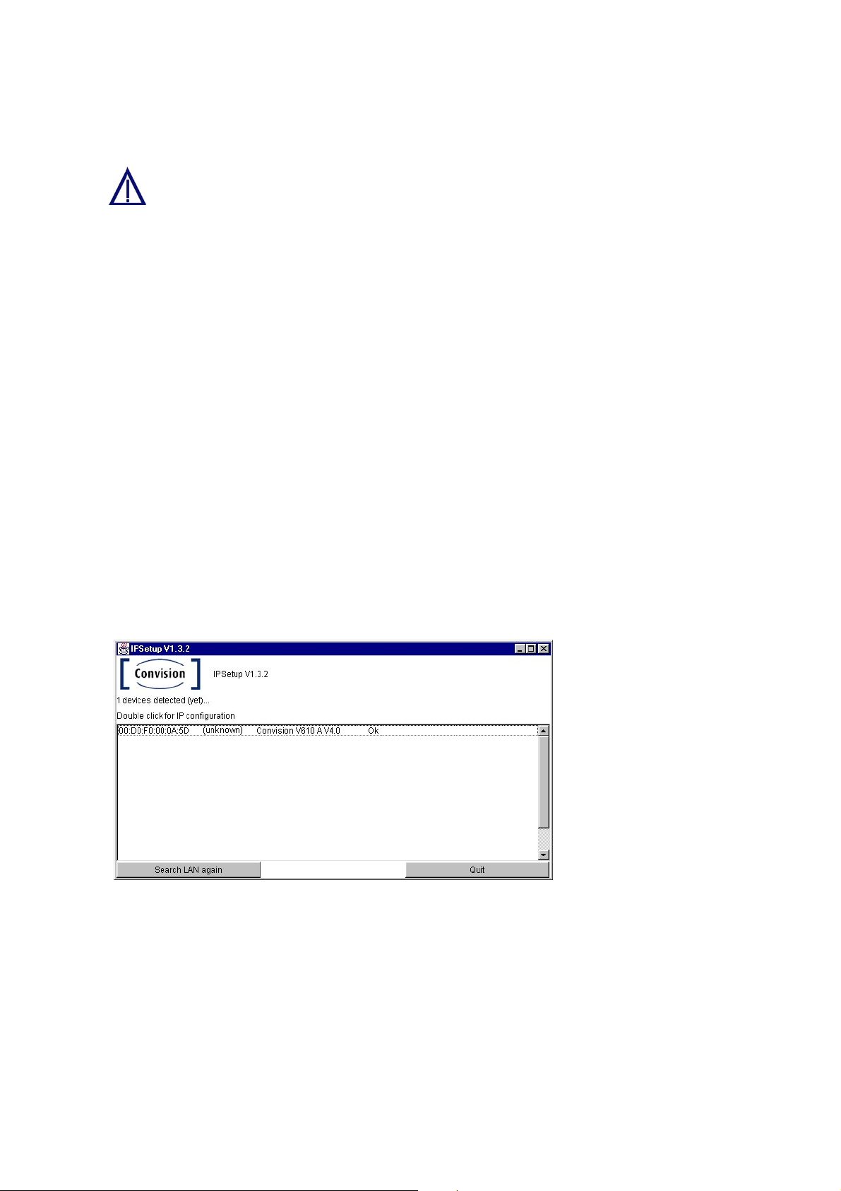
5. After a few moments (max. 1 min) the program will display the Convision V6xx A.
If the program is not automatically started, double-click the entry and then enter
the IP address and the network mask. (For more information about IP addresses
and network masks refer to Chapter 10.8).
Figure 10:
Initial configuration
using Convision
IPSetup
6.3 IP Configuration via a Direct Connection
Using a Cross-Connect Cable
The following hardware and software is required to set up the Convision V6xx A via a
cross-connect cable:
♦ an Ethernet cross-connect cable
♦ a computer with an Ethernet network access
Manual - 19 -

♦ the CD containing the IP Setup software for the Convision V6xx A
Next follow the instructions below:
1. Connect the Convision V6xx A directly to the LAN card in your computer using a
cross-connect cable.
2. Copy the configuration software "IP Setup" from the CD to a directory on your
computer.
3. Open the Convision IPSetup program. In Windows, the program is launched
using "IPSETUP.EXE".
As this is a Java program, it can also be started by opening "java IPSetup".
4. After a few moments (max. 1 min) the program will display the Convision V6xx A.
Double-click the entry and enter the IP address and network mask. (For more
information about IP addresses and network masks refer to Chapter 10.8).
6.4 Deleting the Configuration
If you made a mistake in programming the IP address, network mask or gateway or if
you have forgotten your password, you can no longer contact your Convision V6xx A.
However, in this case, you can delete the configuration by resetting the unit. Once
the Convision V6xx A has been reset, it will be in the initial state, i.e. neither the IP
address nor the MSN have been saved yet.
To delete the configuration of the Convision V6xx follow the instructions below:
1. Briefly press the Reset button on the front of the Convision V6xx A.
2. Then immediately press the "M" button and release it only after the LEDs 1, 2 and
3 have lit up one after the other. If you also want to delete language modules,
other modules and applets that you have already loaded, keep the "M" button
pressed until the LEDs 1 to 6 have lit up.
3. Then release the "M" button.
4. The configuration has been deleted when the Online LED starts blinking in
intervals of one second after the rebooting procedure. The initial configuration
procedure then needs to be repeated.
Caution! Do not press the "F" button at the same time as the
"M" button since this will delete the entire software (firmware)
of the Convision V6xx A!
- 20 - Convision V600 A Series

7 The HTML Pages – Operation and
Configuration
After the first successful connection, enter the IP address of your Convision V6xx A
in the address line of your browser.
The Homepage
The homepage of the Convision V6xx A will be displayed. From this page, you can
access all the viewing and configuration pages.
On the left-hand side you can see the navigation menus for opening the various
pages. At the bottom of this section you will find all the available languages.
On the right you can see a view of the images from all cameras.
Selecting the Language
The language selected upon delivery is either the default language set in the browser
or English. If you want the menus to be displayed in a different language, you have to
select this language at the bottom of the homepage.
In the Configuration / System / Language menu (refer to Chapter 9.1.3) you can
change the default settings and load additional languages.
Useful Notes on Navigation
In the left-hand bar of the browser window, you can see a field with the entry
"Cameras". Click the arrow to the right of this field to display a list of various menu
items. If you click on one of the menu items, another list with submenu items will be
displayed.
A small square to the left of a list item means that this entry is not
subdivided further. Clicking on this list entry will display the associated
page in the right-hand area.
A triangle to the left of the list entry means that there are more submenu
items that can be displayed by clicking with the mouse. Clicking on
these items displays the associated pages.
For the "Configuration" menu, there is another drop down menu below the first one.
This drop down menu contains the items of the individual configuration menus. To be
able to use all the possibilities provided by the Convision V6xx A, you have to
configure it first. For this purpose, please read Chapter 9 - Configuration.
Manual - 21 -
8 Operation
8.1 Cameras
In this menu you can view the images from the connected cameras.
Selecting the Viewing Mode
There are various modes for viewing the camera images. Select the viewing mode by
clicking on it:
♦ Single Shot (JPEG)
♦ Live-optimized with Server Push (Netscape only)
with ActiveX (Internet Explorer only)
♦ Live-compatible with the Java applet developed by Convision
Technology
A list of the cameras and multiple views is displayed.
)
Note: A signed Convision Systems ActiveX Plugin for displaying live streams in
Internet Explorer is available (for more information refer to document “Convision
System Configuration“).
Selecting the Camera
Select one of the individual cameras, or "View of two cameras" (views of 2 cameras
simultaneously), "View of four cameras" (views of 4 cameras simultaneously) or
"View of six cameras" (views of 6 cameras simultaneously). On the right-hand side,
the current image is displayed as 384x288(fullsize). The camera name is displayed
inside the frame, provided you assigned a name under "Configuration / Cameras /
Name".
This icon is displayed if one of the inputs is not connected to a
camera.
If you have selected views of two, four or six cameras, you can select an individual
camera by clicking the respective number button above the image. Cameras 1 and 2
or 1 to 4 are displayed by default.
Selecting the Image Size
Select the image size by clicking one of the three image sizes displayed underneath
the image:
♦ 192 x 144 (halfsize)
♦ 384 x 288 (fullsize); this is the default size
♦ 768 x 576 (hugesize)
- 22 - Convision V600 A Series
When selecting views of multiple cameras, it is not possible to change the image
size.
) Note: The loading time for a large image is longer than for a small image.
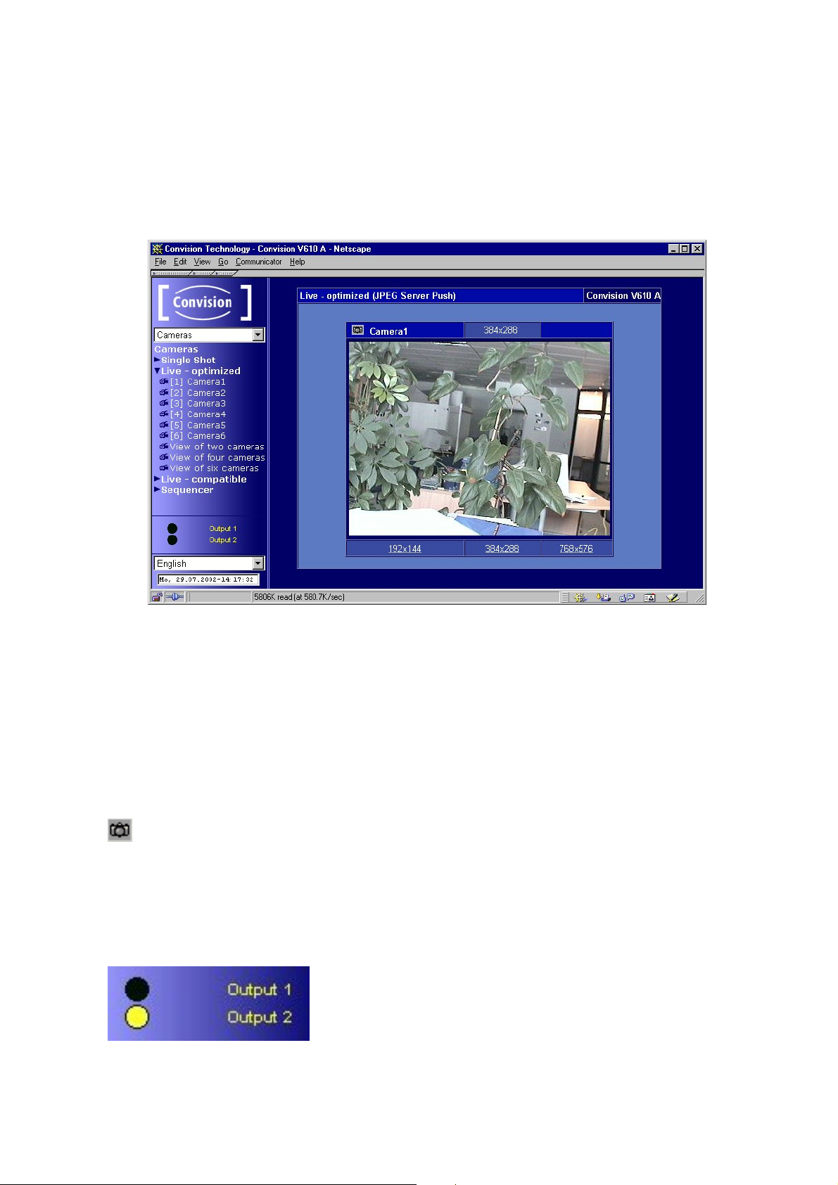
Display
Figure 11: Camera display
When the images are displayed using Live-optimized ActiveX plugin or Livecompatible, you can access a pop-up menu (to display it, click the image using the
right mouse button). This pop-up menu provides options for showing/hiding the date
and time and for starting/stopping the image stream. When using Live-compatible,
you can also flip the image horizontally and vertically and show the camera name
and FPS (frames per second) rate.
Snapshot
In the upper left hand corner of the image in the streaming section you will find
the Snapshot icon. Clicking on this during the streaming will result in a JPEG single
image being taken. With the right mouse button you can save this in the context
menu of your browser.
Activating the outputs
You can activate the outputs by clicking on Output 1 or
Output 2. A black dot indicates that the output is not
activated or has been deactivated, a yellow dot that the
output has been activated.
Manual - 23 -
The “Output (Time)” function, ie automatic activation of the outputs for a
specified time as an action following an event, overrides this function. It is
possible that you will see an inactive output here which has, in reality been
activated by an event.
8.1.1 Controllable Camera
You can connect various controllable cameras to the Convision V6xx A, which can be
operated directly via the user interface. Depending on their designs, these cameras
have different functions. For this reason, the user interface of the Convision V6xx A
varies, depending on the camera connected.
The user interface of a fully controllable camera is shown in Figure 12.
)
Note: The camera control is always displayed as a live stream with a fullsize
image recorded from a single camera.
In some controllable cameras you have to set an internal control address..
For this purpose, please use the addresses starting with "1".
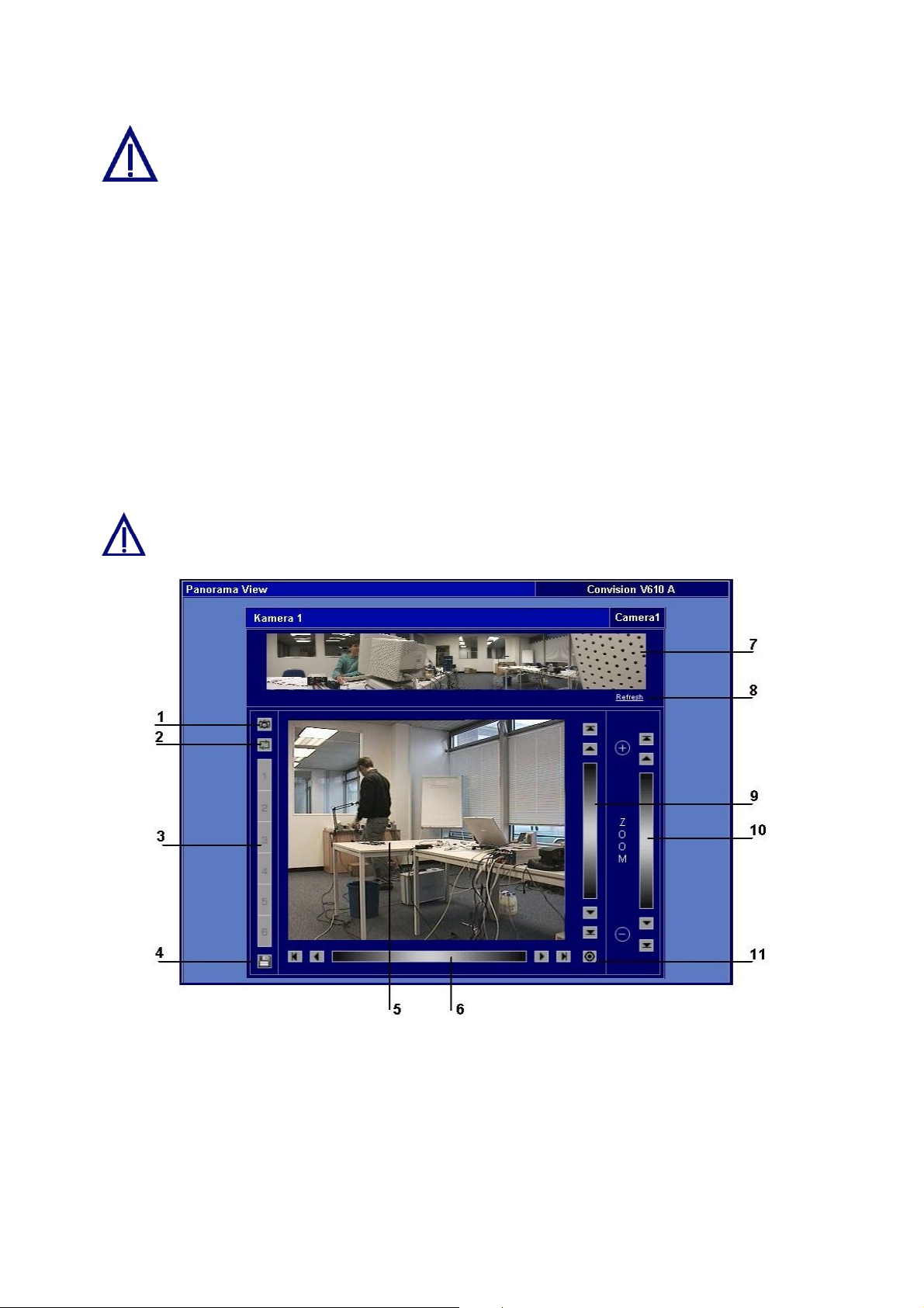
Figure 12: View of a fully controllable camera
1 Snapshot - Clicking on this during the streaming will result in a JPEG single
image being taken. With the right mouse button you can save this in the
context menu of your browser.
2 Preset Tour - The camera can be pre programmed for up to 6 different position
presets which will be displayed sequentially.
3 Camera presets– storage spaces for selected image sections.
Click on the previously stored preset values to focus the camera on those
- 24 - Convision V600 A Series
sections.
4 Save button– opens a dialog box for storing the preset sections.
5 Current camera image – Click a point in the image to focus the camera on the
selected point.
6 Horizontal pan range – infinitely variable panning
Stepwise panning left/right, depending on the zoom factor
Panning to left/right end position
7 Panoramic view of the entire pan/tilt area.
8 Clicking on "Refresh" reconstructs the panoramic view using updated frames.
9 Vertical pan range – infinitely variable panning
Stepwise panning up/down, depending on the zoom factor
Panning to the upper/lower end position
10 Zoom – infinitely variable zooming
Zoom in/zoom out stepwise
maximum zoom factor/minimum zoom factor
11 Travel to the home position of the camera.
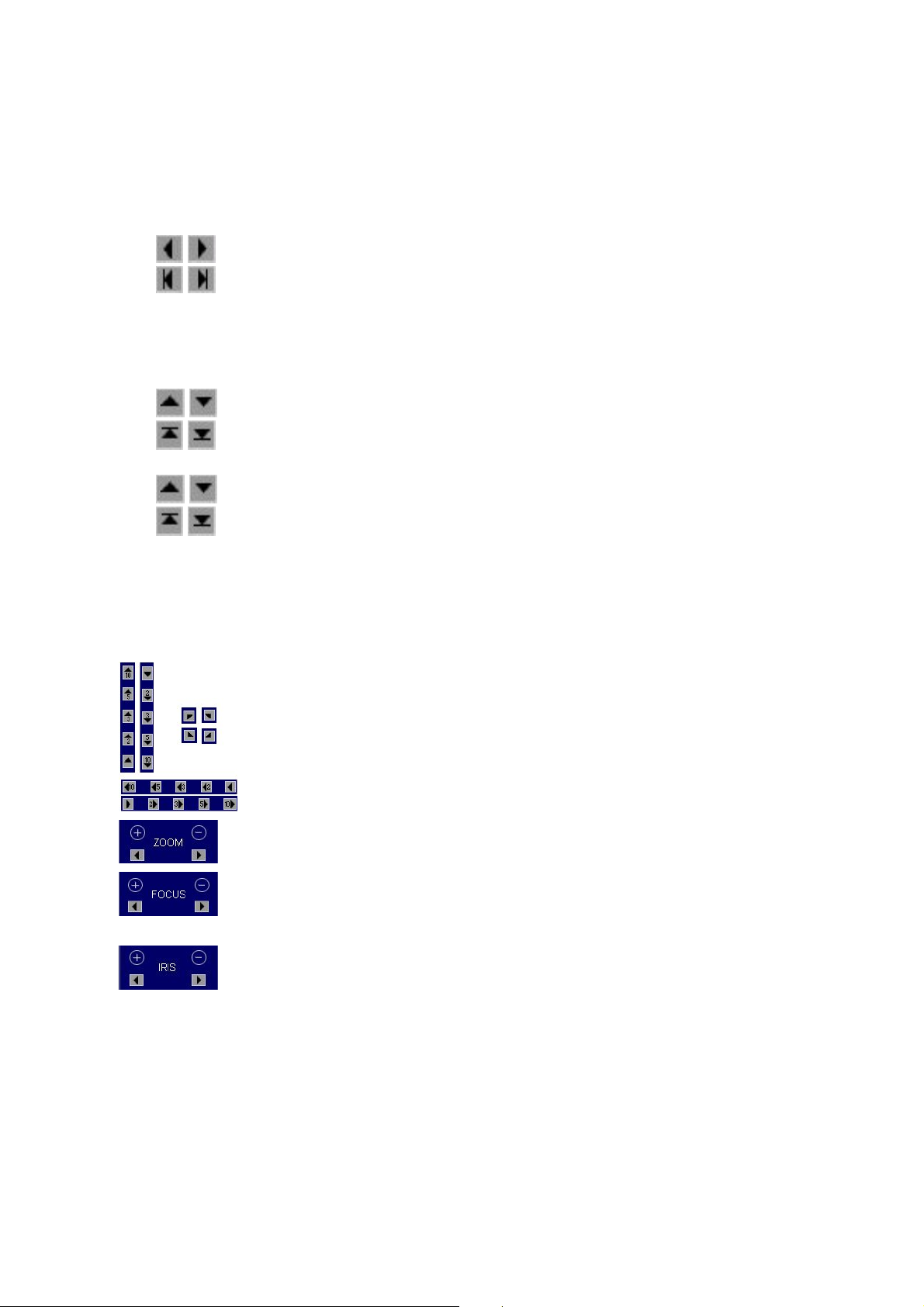
Depending on the type of camera connected, some of the following controls will be
displayed instead of the user interface shown in Figure 12: View of a fully controllable
camera.
By clicking on the triangles the camera swivels in the direction of
the arrow. The angle depends on the zoom factor.
By clicking on the double arrow, the camera will be moved 10
times further in one movement than with the single arrow.
Adjusting the zoom factor
Zoom in/Zoom out
Setting the image sharpness range for cameras without auto
focus.
Close-up focus / remote focus
Adjustment of the light incidence in the lens.
Closed iris/open iris
Saving Presets
)
Note: If the configuration protection function is activated, administrator rights are
required for the storage process.
1. For some controllable cameras you can save specific image sections as preset
sections (Presets). For this purpose, focus on the desired point within the pan
area of the camera.
2. Set the desired zoom factor.
Manual - 25 -

3. Click the diskette icon. A dialog box for saving the current image section related
to a position number is displayed.
4. Click the desired position and assign it a name.
5. Save the data. The dialog box is closed.
Now you can always focus on that point by clicking the respective position number.
The names will be displayed as a tool tip whenever the mouse cursor is positioned
on the number. The preset sections can also be addressed due to an event (refer to
Chapter 9.3).
Preset Tour
1. Configure the desired presets.
2. Click on the icon
3. Click on the desired number position and input the desired amount of time.
4. Save the data.
5. Start the “Tour“ by clicking on start. The black indicator and the ”Tour“ icon will
change to red.
6. End the “Tour“ by clicking on “stop“. The red indicator and the “Tour” icon will
change to black.
)
Note: If the configuration protection function is activated, administrator rights are
required for the storage process.
. This opens a dialogue box.
8.1.2 Sequencer
The sequencer allows you to program the cameras to be viewed sequentially for a
specified time, without having to manually shift between the cameras.
Configuration
♦ Click the activation box before each camera you want to view.
♦ Input the time in seconds you want to view the camera for.
♦ Save the data.
You can also set the sequencing configuration in the
“Configuration/Camera/Sequencer“ menu.
Start sequencer
♦ Click on either Live-optimised or Live-compatible. You will see the images,
depending on your browser configuration, either in Live-optimised or Livecompatible mode.
Stop sequencer
♦ Click on “Save“ in the configuration menu
- 26 - Convision V600 A Series
8.2 Playback (Convision V610 A only)
In the "Play" menu you can view the images saved on the available partitions.
Requirements
♦ First of all, you have to create at least one partition on the hard disk (refer to
Chapter 9.5.1).
♦ Start a recording (to start a recording manually, refer to Chapter 8.3, for a time-
controlled or event-controlled start, refer to Chapter 9.3).
♦ After images have been stored on at least one partition, start the playback
function.
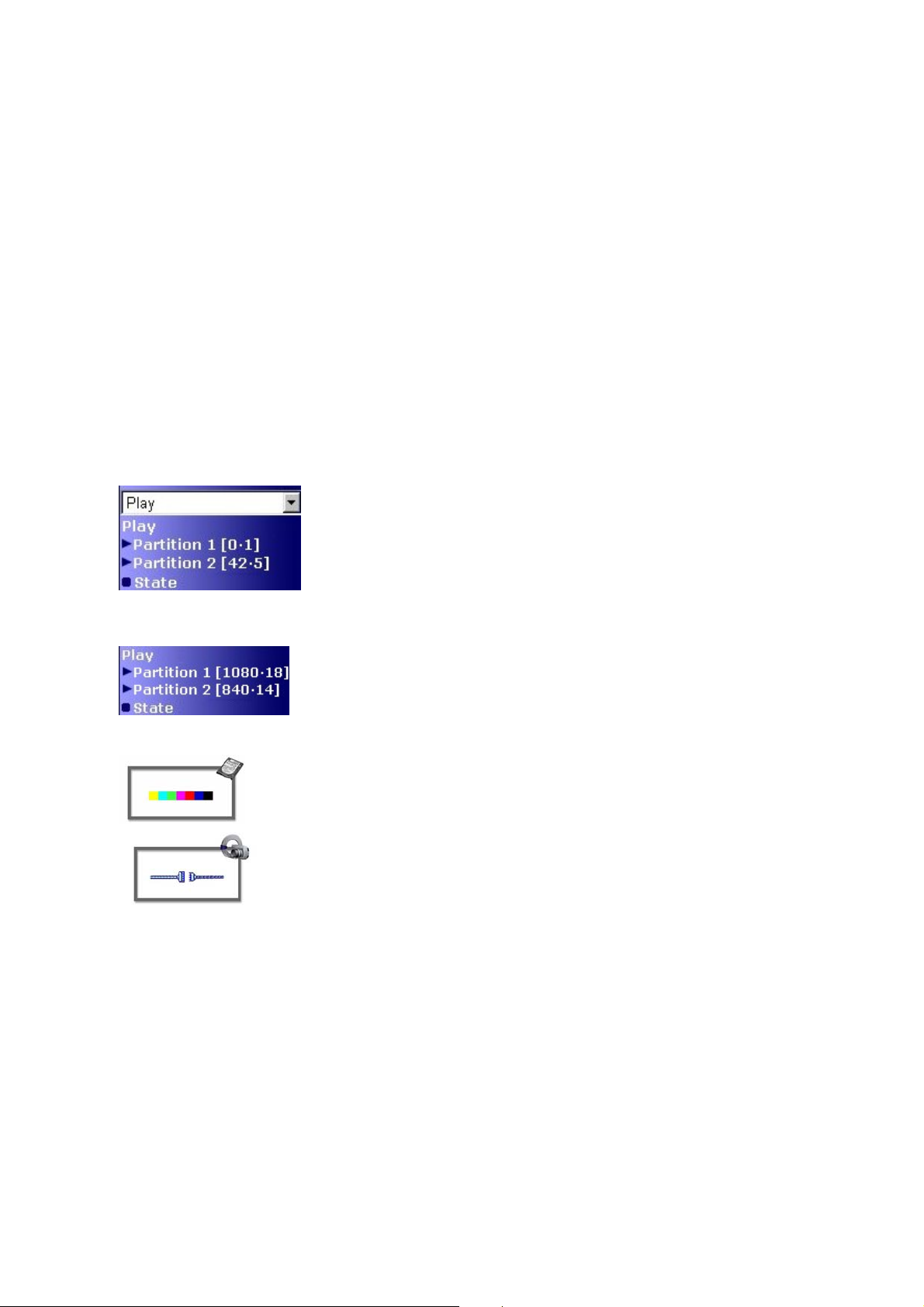
Description of the Numbers behind the Partitions
Long time partition
The numbers in square brackets behind the partition
specify: [the number of recorded images per camera •
the number of cameras recording on this partition]
In our example, the total number of images on partition 2
is 42 x 5 = 210
Event partition
1. Select the desired partition.
2. Select the desired camera and the program to be used for displaying the images,
i.e. either Live-optimized or Live-compatible refer to Chapter 10.2).
The numbers in square brackets behind the partition
specify: [the number of recorded images • the number of
events which have already occurred]
In our example, the number of images per event on
partition 2 is 840 / 14 = 60
If a partition does not have any images, the icon shown
on the left-hand side is displayed.
If a camera should temporarily fail, the icon shown on
the left-hand side is displayed. If there are several
cameras recording on a partition, the symbol will appear
for each image the failed camera should have recorded.
Manual - 27 -
 Loading...