


ii
1st Edition (Mar 17, 2009)
Contents
1. INTRODUCTION..........................................................................................................................................1
1-1 PRODUCT CHARACTERISTICS ...........................................................................................................................1
1-2 MAIN FEATURES...............................................................................................................................................3
2. THE FIRST TIME START............................................................................................................................6
3. MAIN SCREEN............................................................................................................................................12
3-1 DISPLAY SCREEN STYLE.................................................................................................................................13
3-1-1 Split Styles............................................................................................................................................14
3-1-2 Sequencer..............................................................................................................................................15
3-1-3 Event to Zoom.......................................................................................................................................15
3-1-4 Full Screen............................................................................................................................................17
3-2 PTZ CONTROL ...............................................................................................................................................18
3-3 COLOR ADJUSTMENT .....................................................................................................................................19
3-4 LIVE AUDIO VOLUME ADJUSTMENT............................................................................................................... 20
3-5 CAMERA STATUS ............................................................................................................................................20
3-6 ALARM INPUT STA TUS ....................................................................................................................................21
3-7 ALARM OUTPUT STATUS ................................................................................................................................22
3-8 HDD STATUS .................................................................................................................................................22
4. PLAYBACK..................................................................................................................................................24
4-1 SEARCH RECORDED DATA B Y TIME................................................................................................................27
4-2 SEARCH RECORDED DATA B Y EVENT .............................................................................................................31
4-2-1 Event Search by Time ...........................................................................................................................32
4-2-2 Event Search by System........................................................................................................................35
4-2-3 Event Search by Device........................................................................................................................37
4-2-4 Event Search by POS............................................................................................................................38
4-3 PLAYBACK SCREEN STYLES ...........................................................................................................................40
4-4 PLAYBACK COLOR SETTING........................................................................................................................... 43
4-5 PLAYBACK AUDIO SETTING............................................................................................................................43
4-6 PLAYBACK ACCESS MENU .............................................................................................................................44
4-6-1 Snapshot................................................................................................................................................44
4-6-2 Export Log............................................................................................................................................45
4-6-3 Backing up Video Files......................................................................................................................... 47

iii
4-6-4 Playback Setting....................................................................................................................................53
5. SYSTEM SETTINGS...................................................................................................................................54
5-1 CAMERA SETUP..............................................................................................................................................56
5-1-1 Camera Properties.................................................................................................................................56
5-1-2 Detection...............................................................................................................................................58
5-1-3 OSD ......................................................................................................................................................60
5-1-4 Camera Color........................................................................................................................................61
5-1-5 Recording Schedule..............................................................................................................................62
5-1-6 PTZ .......................................................................................................................................................68
5-2 DISPLAY .........................................................................................................................................................72
5-2-1 Sequencer..............................................................................................................................................72
5-2-2 Split.......................................................................................................................................................73
5-2-3 Multiplexer (Optional)..........................................................................................................................74
5-3 USER ACCOUNT MANAGEMENT.....................................................................................................................76
5-4 ALARM...........................................................................................................................................................79
5-4-1 Add/Modify/Delete Alarm Rule............................................................................................................79
5-4-2 Alarm Device Configuration.................................................................................................................90
5-5 NETWORK ......................................................................................................................................................94
5-5-1 General..................................................................................................................................................94
5-5-2 DDNS....................................................................................................................................................97
5-5-3 Remote Control.....................................................................................................................................98
5-5-4 Network Share ......................................................................................................................................99
5-6 STORAGE......................................................................................................................................................101
5-6-1 Disk.....................................................................................................................................................101
5-6-2 Disk Recycle.......................................................................................................................................102
5-6-3 RAID Box...........................................................................................................................................102
5-7 POS .............................................................................................................................................................104
5-7-1 POS Setting.........................................................................................................................................105
5-8 SYSTEM........................................................................................................................................................111
5-8-1 Time Setting........................................................................................................................................111
5-8-2 Security...............................................................................................................................................114
5-8-3 COM ...................................................................................................................................................114
5-8-4 Others-Watchdog.................................................................................................................................115
5-8-5 About...................................................................................................................................................115
6. REMOTE OPERATION............................................................................................................................116

iv
6-1
DOWNLOAD DVR CLIENT (DVRSETUP)........................................................................................................117
6-2 REMOTE OPERATION ....................................................................................................................................117
6-2-1 Remote Display Mode ........................................................................................................................118
6-2-2 Remote Setup...................................................................................................................................... 119
6-2-3 Snapshot..............................................................................................................................................121
6-2-4 Full Screen..........................................................................................................................................121
6-2-5 Remote Playback.................................................................................................................................123
6-3 REMOTE DVR LOG QUERY.......................................................................................................................... 126
6-4 REMOTE OPERATION LANGUAGE .................................................................................................................127
6-5 DVR PLAYER ...............................................................................................................................................128
6-6 DVR REMOTE BACKUP................................................................................................................................131
6-7 REMOTE REBOOT DVR................................................................................................................................132
6-8 REMOTE UPGRADE DVR FIRMWARE............................................................................................................133
6-9 REMOTE MONITOR VIA 3G/GPRS/WI-FI MOBILE HANDSETS......................................................................135
6-9-1 Wi ndow Smartphone and Handsets.....................................................................................................135
6-9-2 Java Smartphone and Handsets...........................................................................................................140
7. APPENDIX .................................................................................................................................................150
A. HARDWARE COMPATIBLE LIST.................................................... FEHLER! TEXTMARKE NICHT DEFINIERT.
B. FAQ..........................................................................................................................................................151
C. INTERNET CONNECTION............................................................................................................................154
D. MAINTENANCE .........................................................................................................................................155
E. CUSTOMER SERVICE ................................................................... FEHLER! TEXTMARKE NICHT DEFINIERT.

1
1. Introduction
1-1 Product Characteristics
Optimum Replacement for Time-lapse Recorder
Traditional Time-lapse Recorder is a mechanical device. It is very easy to break down after
long-term operation and it causes many problems such as: the overly used magnetic heads
which cause blurred image; tapes need to be changed often and manually; the recording time is
not long enough; the management of recorded tapes is complicated; inefficient when trying to
locate the needed data; recording a huge amount of useless images, etc.
This DVR system adopts digital recording technology. The quality of images will not
deteriorate with time. W ith its high compression rate, the storage time can last for months under
normal applications. The overwrite operation mode will overwrite the earliest data, and no m ore
tape change is required. Motion detection function will enable the recording only when there is
motion of the objective, and makes the system and data retrieval more efficient.
High Reliability
Normal PC digital surveillance system adopts the MS-Windows OS (Operating Systems). Such
kind of system is so often to crash. It usually makes a negative impression which digital
surveillance system is unreliable.
This DVR system adopts Embedded-Linux OS. Our advanced embedded technology condenses
the entire system into a tiny flash module, which makes the system more reliable. Even when
the power fails, the system will re-boot and return to normal operation in less than one minute.
Longer Recording Days
This DVR system adopts the advanced MPEG-4 compression to store the video images. It
allows you to record more data on the same capacity of hard disks.
Ease of Operation
Mouse clicking on the Graphical User Interface controls all the operations. No keyboard is
needed so that it is most suitable for the security guards and normal non-IT based users to use.
Multi-Function

2
Function of one set of DVR system = Time-lapse Video Cassette Recorder + Multiplexer
processor + Motion Detection Processor
You can backup the data to CD-R/RW, remotely monitor the images and still recording the
current video data at the same time.
IP Surveillance
Instead of only analog camera, from V5.03, this DVR system also supports IP camera
connections to build IP surveillance systems to enjoy higher scalability, lower deployment cost,
and greater intelligence of IP surveillance compared to CCTV.
High Resolution Display and Wide Screen Support
To provide better screen quality, DVR supports 1024*768 and above high resolution and
supports 16:9 wide screen display without picture distortion. User can select best DVR display
resolution according to the monitor he uses.
64 High Channel DVR Solution
From V6.00, DVR supports max 64-channel camera connections with 32 channel analog
cameras and 32 channel IP cameras to build up 64 ch hybrid DVR system or pure 64 channel IP
cameras to build up 64 ch NVR system. With th is 64 high channel camera connection capability,
customer can considerably save DVR construction cost.
3
1-2 Main Features
Items Description
OS Embedded Linux
Video Inputs 8/16/24/32 channels in BNC jack
Video Outputs D type 15 Pins VGA and TV-Out (Optional)
Video Format NTSC/PAL
Audio Input/Output 8/16/24/32 channel inputs and 1 channel output
PC Interface PCI Slot
System
Multi-Tasking Yes
Frame rate Real time display
Resolution 1024*768 and above resolutions
Display Splits
4:3 monitor: 4, 6, 8, 9, 10, 13, 16, 25, 36, 49, 64
16:9 monitor: 4, 6, 8, 9, 14, 17, 24, 36, 48, 65
Sequencer 1, 4, 16
HDD Usage Display Yes
Hidden Camera Yes
Video Loss Detection Yes
Display Password Protection Yes
Display
Color Adjustment Brightness/Contrast/Hue/Saturation for each camera
Compression MPEG 4 like Compression
Resolution
NTSC: 720*480; 320*240
PAL: 720*576; 320*240
Frame rate per channel
NTSC: 15fps@720*480; 30fps@320*240;
PAL: 12.5fps@720*576, 25fps@320*240
Pre-Schedule Recording
By 7days x 24hours, set each hour as:
recording by events, continuously recording, non-recording
Motion detection area
Define any 8x8 cell for motion detection. Free combinations of detected
areas. No limitation on the number of detection areas.
Motion detection sensitivity 10 ranges per camera
Smart Motion Recording
Automatically adjust recording frame rate according to motion
occurring to save HDD space. (Low frame rate recording w/o motion
occurring and high frame rate recording with motion occurring)
Recording
Pre-Recording 0~20 sec
4
Post-Recording 0~600 sec
Watermark Yes
Date Code
Recording includes time/date information.
T o prevent date code from being modified
Playback channels Max 16 channel Sync playback
Playback mode Play, Pause, frame by frame play, fast forward, fast backward
Video Enhancement De-interlace, Sharpen
Search Search by time, date and event.
Playback
Image Adjustment Brightness/Contrast
Internet/PSTN/LAN by Ethernet/ Modem
Networking
Static IP, PPPoE, DDNS, DHCP
3G/GPRS/Wi-Fi Remote monitoring
Remote monitoring via JPEG or MPEG 4 streaming.
Max. 16 clients access simultaneously
Max. 16 ch sync playback
Remote playback
Web Viewer
Remote backup
Max. 64 DVR connections with 1024 Ch
Remote monitoring
Remote playback
Remote backup (One time backup or periodical backup)
Central Management System
E-MAP
Max 200 DVR connections
Remote DVR Health Check
Control Center
Remote Time Sync.
Remote
Functions
Remote Backup by Windows Network Neighborhood
Inputs 4/8/12/16/24/32 NC/NO inputs
Outputs 4/8/12/16/24/32 NC/NO relay outputs
IO & Camera Relations 1-1, 1-many, many-1, many-many
Alarm Behavior
Alarm to Zoom, Alarm to recording, Alarm to Notice (by Email / FTP /
SMS), Alarm to DO output
Alarm
Tamper Protection Camera covering/spray detection
Storage &
HDD Interface Support IDE & SATA HDD s wi t h Max 24TB

5
RAID support
*Support IDE/SCSI RAID
*Support RAID 0~5, RAID event notification & RAID configuration
Backup
USB/ IDE burning device (CD-R/RW, DVD±R/RW); USB storage (Pen
Drive, HDD)
Backup
HDD SMAR T Diagnostics Yes
128 user accounts
Multiple levels user authority (Admin/Supervisor/User)
Password protection
Password expiry management
PTZ camera support Yes
Power Down Management Yes. Auto-recovery when power back
Watchdog Yes Hardware Watchdog.
Time Zone/Daylight Saving Yes
AVI Format Export Yes
Time Sync Support Time Server, FM and RTC Time Sync
POS Support POS integration.
Other
UI Language
9 languages in single software: English, French, German, Japanese,
Portuguese, Spanish, Dutch, Traditional Chinese and Simplified
Chinese.
* Specifications subject to change without notice
6
2. The First Time Start
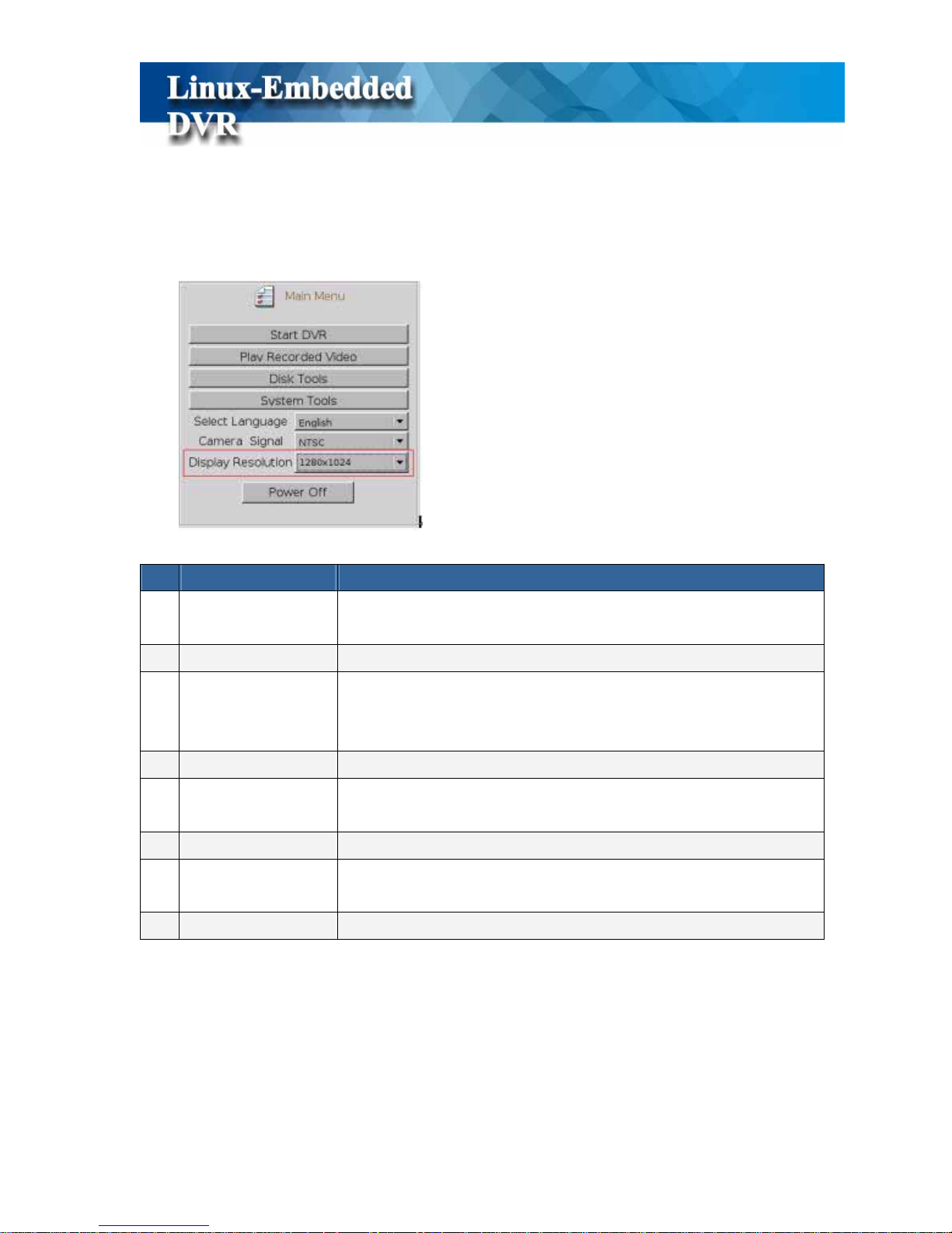
When starting DVR for the first time, you should have following configurations,
Function Description
1 Start DVR
Quick access to DVR main screen. If you don’t click this button,
DVR will automatically go into Main screen after 5 seconds
2 Play Recorded Video Playback only. Quick access to playback mode.
3 Disk Tool
Tools for HDD storage device including Scan Disk, S.M.A.R.T
Diagnostic, Disk manager to assign camera to HDD and RAID
configuration.
4 System Tool Reset Configuration
5 Select Language
Select preferred language (Traditional Chinese, English, Japanese,
French, German, Portuguese, Dutch and Spanish)
6
Camera Signal
Switch DVR to NTSC or PAL mode according to camera signal type
7
Display Resolution
Select the best display resolution among the resolutions that monitor
supports
8
Power Off
To turn off the DVR
7
z Select Language
This DVR system supports eight kinds of languages that including Traditional Chinese, English,
Japanese, French, German, Portuguese, Dutch and Spanish. You can select your preferred
display language before starting DVR system.
z Select Camera Signal
Before you enter DVR monitor screen, you should select correct camera signal, NTSC or PAL
according to the cameras connected to the DVR. Please be noted that incorrect camera signal
will cause abnormal image format.
z Select Display Resolution
To provide better display screen quality , this DVR system supports m ultiple display resolution s.
DVR will automatically detect the resolutions that monitor supports and list them in the menu.
We suggest to select the highest resolution listed in the menu.
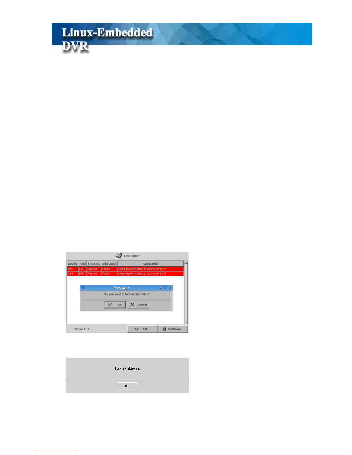
z Disk Tool-Format HDD
If DVR is not equipped with an install ARECA internal RAID Box, wait 5 seconds for time out
and then the system will detect new hard disks and ask if you want to format hard disk.
Click “OK” to start formatting. Follow the on-screen instruction to continue.
8
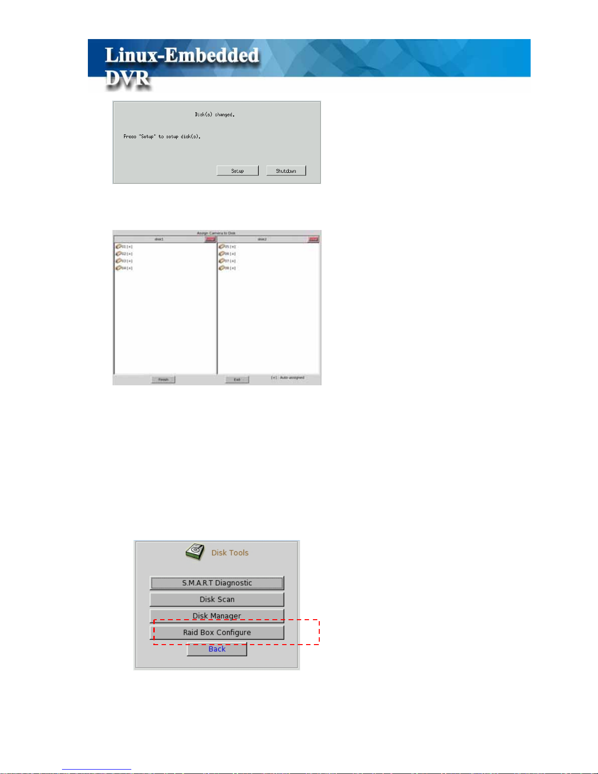
Click “Setup” to see the figure below.
Click “Finish” to complete the setting and the system will restart automatically.
z Disk Tool-RAID Box Configuration
If DVR is equipped with ARECA RAID Box, you should have RAID configuration before you
start to assign camera to disk in “ DISK Manger” of “ Main Menu”.
(1) Step 1: Go to Main Menu>Disk Tool>RAID Box Configure
9
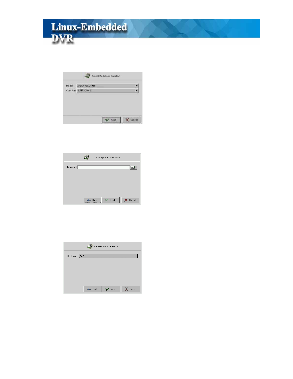
(2) Step 2: Select RAID Model & COM Port
Please Select “ARECA AREC5030” as RAID Model and select “USB COM 1” as COM
Port interface to sent RAID alarm message to DVR.
(3) Step 3: Authentication
The default password is “0000”.
(4) Step 4: Select RAID/JBOD mode
Because ARECA 5030 RAID Box is SATA interface with host, please select RAID mode.
JBOD is for IDE interface.
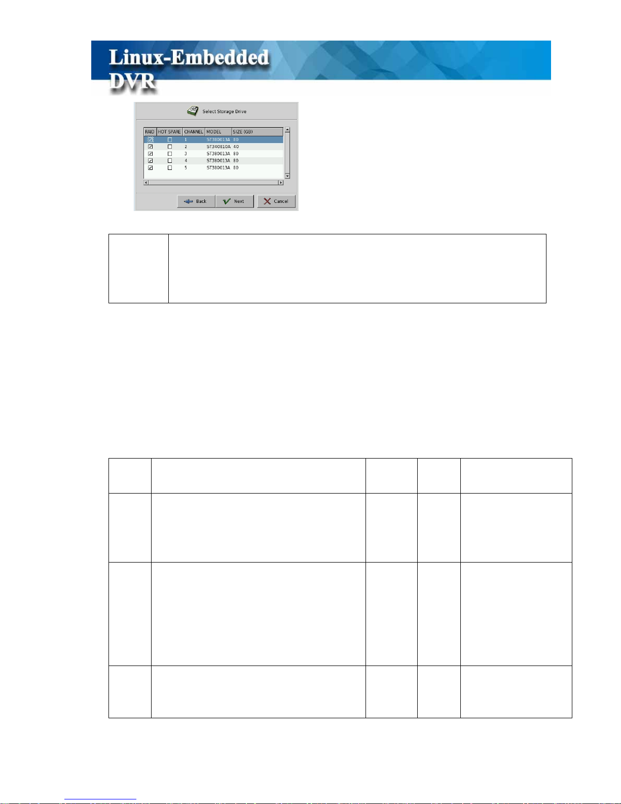
(5) Step 5: Select RAID mode
Please assign each disk (Channel) as “ Hot Spare” or “RAID” disk.
10
!
Note
1. RAID and Hot spare can’t be selected in the same channel (HDD).
2. Only one hot spare HDD can be selected.
3. It’s meaningless to select Hot spare in RAID Level 0
.
(6) Step 6: Select RAID Level
New M-series support RAID 0~5 levels. Below please see the comparison between RAID
0, 0+1, 3 and 5. With properly configured, the RAID can provide non-stop service with
high degree of fault tolerance. The RAID function allows two HDD failures without
impact on the existing data stored in the HDD and failed drive data can be reconstructed
from the remaining data and parity drives. Please have the proper configuration according
to your requirement.
RAID
Level
Description Min
Drives
Max.
Drives
Data Reliability
0
z Also known as stripping.
z Data distributed across multiple drives in
the array.
z There is no data protection
1 5
No data protection
1
z Also known as mirroring
z All data replicated on N separated disk. N
is always 2.
z There is a high availability solution but
due to the 100% duplication, it is also a
costly solution.
2 2
High than RAID 3, 5.
3
z Also known Bit-Interleaved parity.
z Data and parity information is subdivided
and distributed across all disk.
3 5
*Lower than RAID 1.
*High than a single
drive
11
z Parity must be the equal to the smallest
disk capacity in the array.
z Parity information normally stored on a
dedicated parity disk.
5
z Also known Block-Interleaved Distributed
Parity.
z Data and parity information is subdivided
and distributed across all disk. Parity must
b
e the equal to the smallest disk capacity
in the array.
z Parity information normally stored on a
dedicated parity disk.
3 5
*Lower than RAID 1
*Higher than a signal
drive.
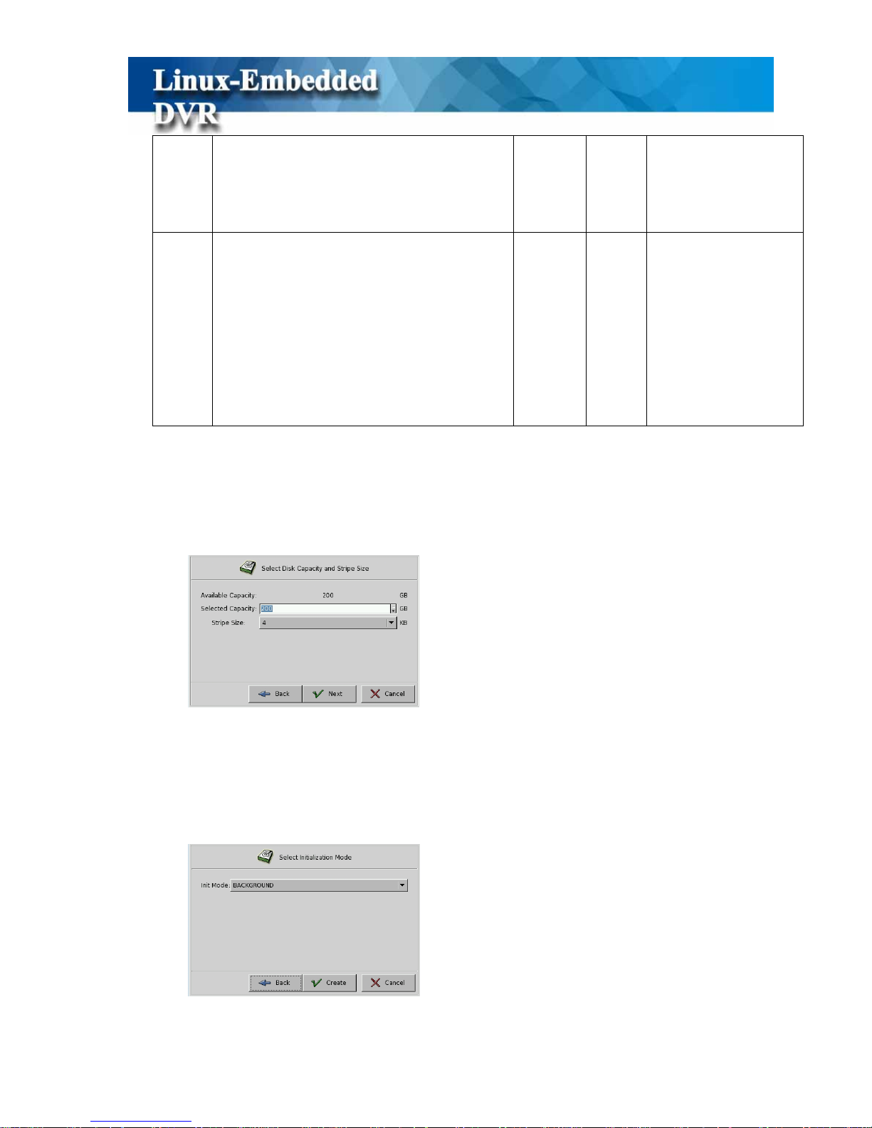
(7) Step 7: Select capacity and stripe size
“ Available Capacity” means the max capacity that can be used in the RAID disk. You can
select how much disk space that you want to use. The RAID box provides the options of
Strip size that you use.
(8) Step 8: Initialization
The final step is initializing the RAID Box. There are two modes for selection-Foreground
and Background. Foreground means disk can be used after finishing the RAID
configuration. Background means disk can be used during executing RAID configuration.
12
3. Main Screen
13
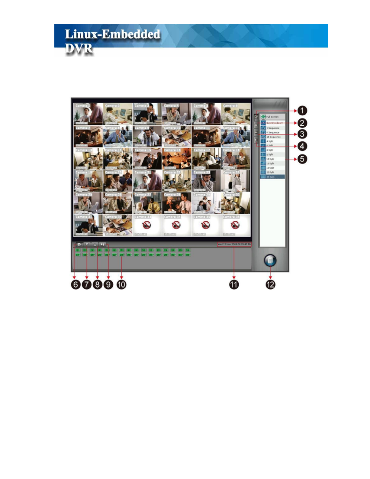
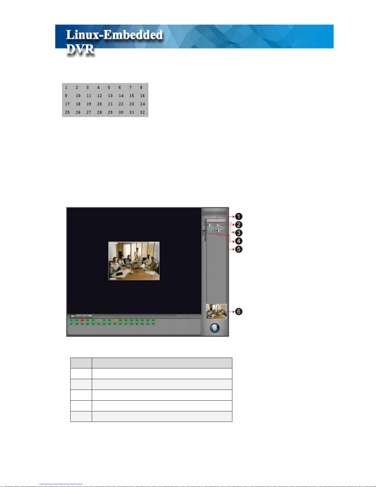
The controls in the main screen including:
3-1 Display Screen Style
If “Monitor Password Protection” function is enabled (Please refer to Chapter 5-3 User
Account Management and Chapter 5-8-2 Security), the system will request you to enter User
name and Password before seeing the live monitor . Click the Access button on the bottom
right of main screen and it will show the DVR Access Menu as below,
Function Description
1 Display Screen Style
List “Full Screen”, “Event to Zoom”, “Sequencer” and
multiple “Display Split” styles.
2 PTZ Control List PTZ Control Menu
3 Color Adjustment
List four color parameters including Contrast, Brightness,
Chroma and Saturation
4 Audio V olum e Setting Adjust live audio volume
5 Control Window
Control Window for “Display Screen Style”, “PTZ Control,
“Color Adjustment” & “Audio Volume” function
6 Camera List List all of DVR channels and each camera status
7 Alarm Input
List all of alarm input devices and status of each alarm
device.
8 Alarm Output
List all of alarm output devices and status of each alarm
device.
9 HDD Status Display HDD status
10 Status Window Camera, Alarm Input, Alarm Output HDD Status Window
11 Date/Time Display current date and time
12 Access Menu
List Access functions including “ Playback”, “ Setup” and
“ Monitor Login” function

14
Click “Login” tab and enter username and password to login to DVR monitor screen.
When you click “Display Screen” , it will show four major screen styles including “ Full
Screen”, “Event to Zoom”, “Sequencer” and “Split Style” in the Control window. You just click
any screen option in the Control Window to switch to the screen style you want.
3-1-1 Split Styles
This DVR system supports two types of split styles according to the monitor you install. For the
4:3 monitor, it will support 4, 6, 8, 9, 10, 13, 16, 25, 36, 49 and 64-split styles. For the 16:9
wide screen, it will support 4, 6, 8, 9, 14, 17, 24, 33, 36, 48 and 65-split styles. The split styles
that DVR supports will be listed in the Control Window. Y ou just need to click on any split s tyle
in the Control Window and the screen will switch to the split style you select. You can also click
Control Window

15
any channel to enlarge the screen picture by two steps and click it again to back to the original
split style. The order of cameras displayed on each split style can be configured in the system
setting menu.
3-1-2 Sequencer
This DVR provides three types of sequencer styles including 1, 4 and 16. Just click one of the
Sequence styles and it will display camera screen in sequence. You can set up the “Sequencer
Order” and the “Sequencer Duration” in the “Display Setting” menu. Please refer to the Chapter
5-2-1 Sequencer.
3-1-3 Event to Zoom
There are two types of Events to trigger camera zooming. One is Motion event and the other
one is Alarm event.
If you want to enable this function, firstly you should go to Setup> “Alarm” menu to set up
“Motion to Zoom” or “Alarm (DI) to Zoom” Rule. Please refer to “Chapter 5-4 Alarm”.
Click
Event to Zoom icon in the Control Window to switch to “Event to Zoom” display
style.
3-1-3-1 Rule of Event Zooming
(1). When the DVR detects motion or alarm on the channel set with Motion to Zoom or Event to
Zoom, it will immediately pop up this channel picture to the “Zoom-in Window” and the
original position of that channel will be replaced with a “ Motion/Alarm” legend and marked
with a red frame.
Any channel without set with “ Motion/Alarm to Zoom” function will not be popped up to the
“Zoom-in Window” or marked in red frame even DVR detects motion or alarm in this channel.
(2). If DVR doesn’t detect any other motion or alarm, the current zooming channel will be

16
continually displayed in “Zoom-in Window”. If yes, the zooming channel will keep displaying
in “Zoom-in Window” for three seconds and then, will be replaced by any channel waiting for
zooming. If DVR detects more than one motion or alarm channels simultaneously, the zooming
rule will be as below,
z The current zooming channel will be the first priority for zooming in again for another
three seconds and others will stay in their positions and be marked in red fram es to wait for
zooming in after three seconds. However, the max zooming time for the same channel is
nine seconds. After nine seconds, even DVR detects motion or alarm on this channel, it
will not be popped up to the Zoom-in Window again until there are no other concurrent
motion/alarm channels and other channels with motion/alarm will replace it to be popped
up in Zoom-in Window according this rule.
z If the channel stayed in it’s position waits for popping up but motion/alarm on this channel
disappears during the waiting time, it will not be zoomed in and the red frame marked in
this channel will disappear.
z If DVR doesn’t detect the current zooming channel with motion or alarm again, the first
priority of the zooming-in channel in waiting list is the one of which channel number is the
smallest. For example, if DVR detects concurrent motions or alarms on channel #3 and
channel #4, the channel #3 will be zoomed in to the Zoom-in Window firstly for three
seconds and the channel #7 marked in red frame will keep to stay in it’s position waiting
for zooming in after three seconds.
3-1-3-2 Zoom in a Specific Channel
If you want to focus on a specific channel, you can set up just to zoom in that channel. In the
Event-to-Zoom mode, click any channel you only want to zoom in and this channel will be
popped up to the Zoom-in Window immediately marked in yellow color frame and the original
position of this channel will be replaced by a “locked picture” legend. In this configuration,
even DVR detects other channels with motions or alarms, these channels will not be popped up
to the Zoom-in Window but just stay in their positions marked in red color frames. You can
click the Zoom-in Window to cancel the configuration of “Zooming in a Specific Channel”.

17
3-1-4 Full Screen
When you click “Full Screen” function in Control Window, DVR will maximize the display
screen to full screen without user interface.
18
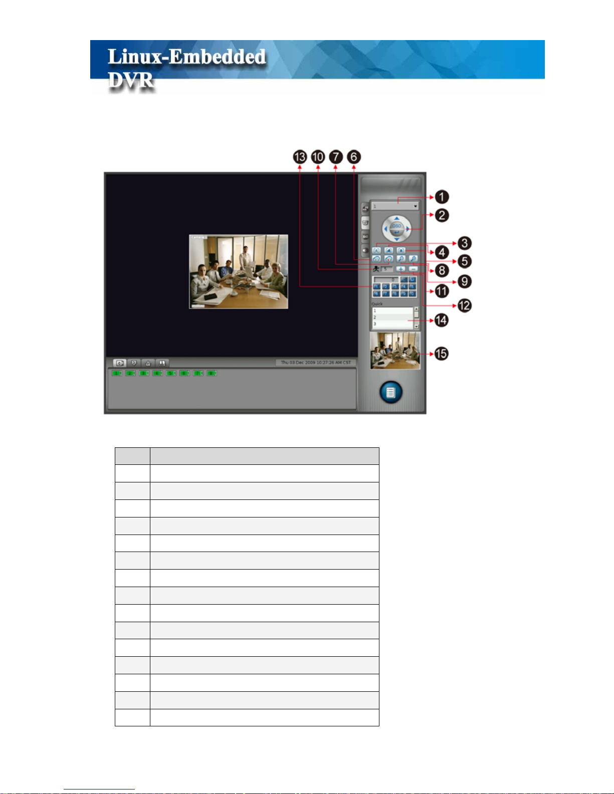
3-2 PTZ Control
Function
1 PTZ Channel
2 OSD Menu
3 Auto Focus
4 Focus Far
5 Focus Near
6 Start Auto-pan
7 Stop Auto-pan
8 Zoom Out
9 Zoom In
10 PTZ Speed
11 Speed Up PTZ
12 Slow Down PTZ
13 Preset Point
14 Quick Select
15 Preview Window
19
When you click “PTZ Control” Tab, it will show PTZ Control Menu in Control Window.
Click PTZ Channel bar and below channel menu will list for your selection.
By selecting any channel that with PTZ function (Please refer to Chapter 5-1-6 PTZ Camera
Setting), PTZ Control menu will show in the Control Window. You can see each button
definition in above PTZ control table.
3-3 Color Adjustment
When you click “Color Adjustment” Tab, it will show “Color Adjustment Parameters” in
Function
1 Camera Channel
2 Contrast
3 Brightness
4 Chroma
5 Saturation

20
Control Window. Firstly, click “Camera Channel” bar and it will list camera channel for your
selection.
Select any channel and then adjust each color parameter according to your requirement. If you
don’t want to provide “Color Adjustment” function in Monitor mode, you can disable this
function in the “System Setting” menu. Please refer to Chapter 5-8-2 Security Setting.
3-4 Live Audio Volume Adjustment
When you click “Audio Volume” adjustment Tab, it will show the tool bar for the adjustment of
Live Audio Volume. The source of Live Audio comes from the microphone connected to the
DVR Mic-in connector.
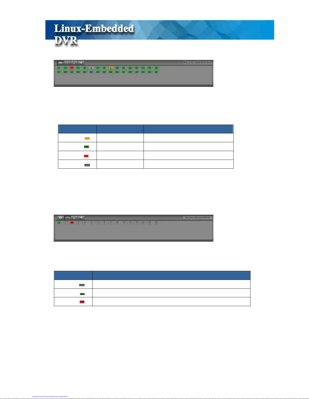
3-5 Camera Status
The Status Window shows total camera channels that DVR can be connected and each camera
21
status as below picture.
The number marked in each camera legend represents the number of camera channel. The color
of each camera legend indicates camera status as below definition.
Color Recording Mode Status
Orange ( )
Full recording
Green ( )
Motion-sensor Motion not detected
Red ( )
Motion-sensor Motion detected & recording
Gray ( )
No recording
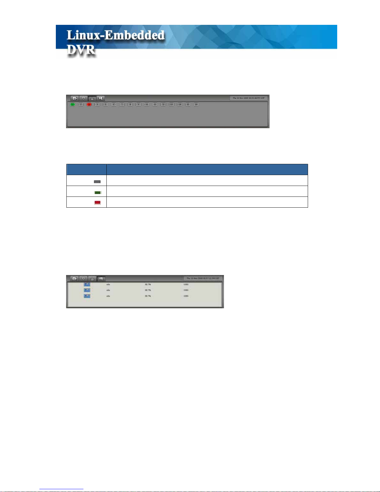
3-6 Alarm Input Status
When you click Alarm Input Status Tab, the Status Window will show the total Alarm Input
devices that this DVR can be connected and the status of each device as below.
Color Status
Gray ( )
Alarm Input device is disabled
Green ( )
Alarm Input device is enabled but alarm device is not activated
Red ( )
Alarm Input device is enabled and alarm device is activated
22
3-7 Alarm Output Status
When you click Alarm Output Status Tab, the Status Window will show the total Alarm Output
devices that this DVR supports and the status of each device as below.
Color Status
Gray ( )
Alarm Output device is disabled
Green ( )
Alarm Output device is enabled but alarm device is not activated
Red ( )
Alarm Output device is enabled and alarm device is activated
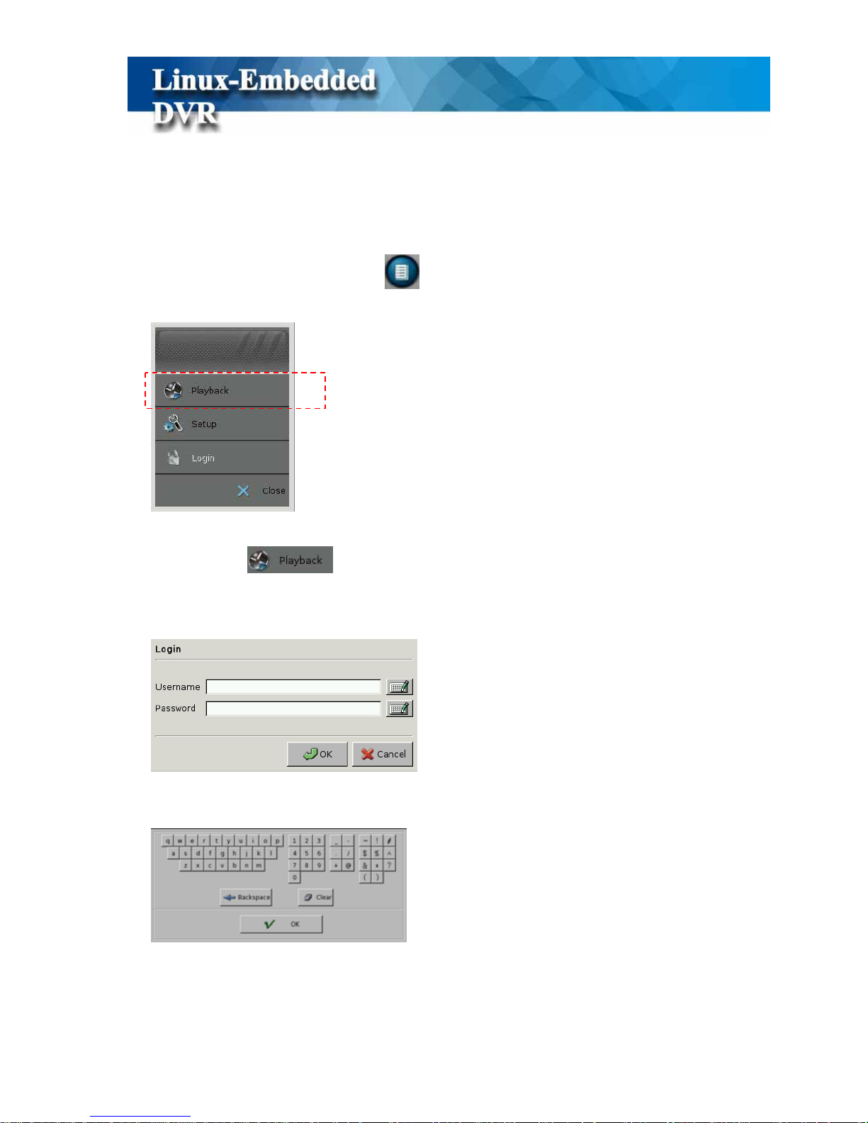
3-8 HDD Status
When you click HDD Status Tab, the Status Window will display HDD status as below.
Each row in the Status Window represents each HDD status. The 3
rd
Column lists the
percentage of HDD free space and the 4th column shows the rest of HDD space. When you start
using a new hard disk (for example, a hard disk with capacity 80GB), the percentage of free
space will be very close to 100% (e.g. 99%), and the color will be BLUE.
However, as recording continues, the available space will diminish. When the remaining
available space is less than 4GB, the display color will change to ORANGE. This serves as a
warning message that the system will soon enter the Recycle Mode; which means, the earliest
recorded data will be replaced by the newest recording data. If you would like to keep all the
data, this is the time to swap a new hard disk.
If the disk has not been changed and the recording continues, the system will go into Recycle
Mode when the hard disk free space is less than 2.5GB. The color of “Hard Disk Free Space”

23
will turn RED.
!
Note
z This DVR system supports maximum six HDDs without RAID
function.
z
This DVR system supports maximum six HDDs volumes with RAID
function.
24
4. Playback
By clicking the button of Access Menu on the bottom right of main screen, it will pop up
the Access Menu as below.
Click “Playback” tab and it will prompt you to enter username and password to
login to the Playback Menu as below.
Click on the keyboard icon to enter the user name and password of “Administrator”.
25
!
Note
1. The preset user name and password of Administrator are as below,
z Preset user name: admin
z Preset password: 1111
2. If “Playback Password Protection” function is enabled, you need to enter
administrator user name and password for Login authorization. Please refer
to Chapter 5-8-2 System->Security for the authorization of playback.
26
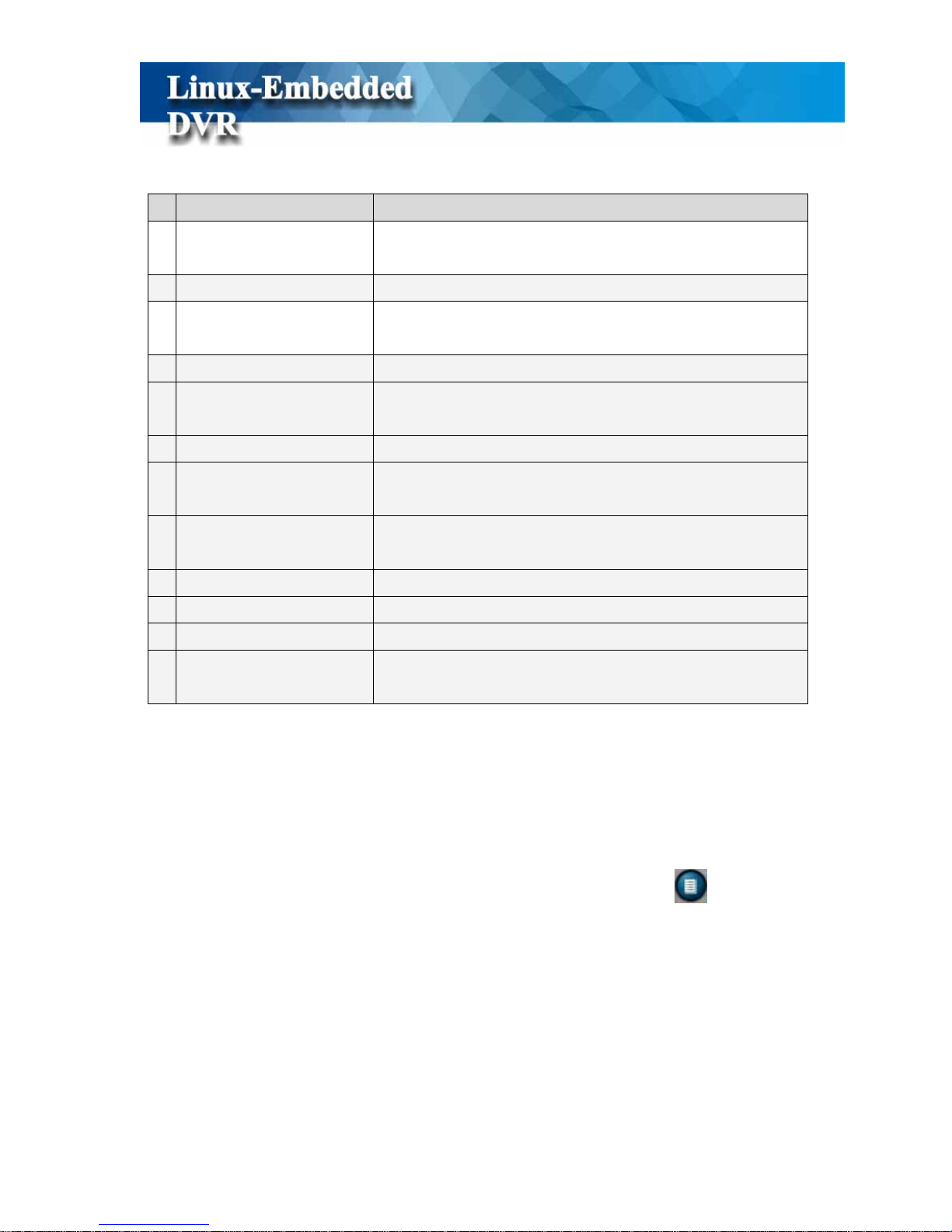
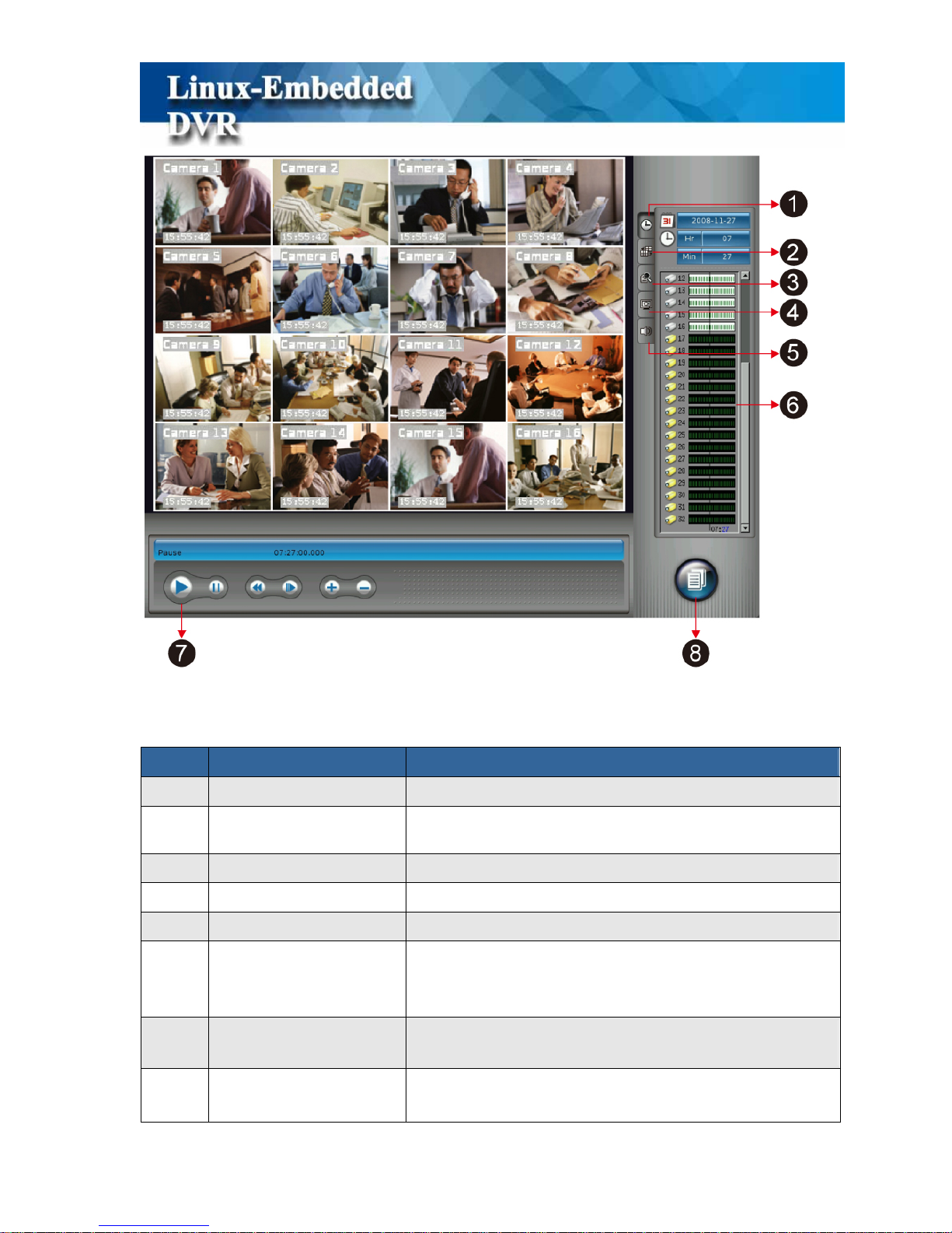
The controls of Playback functions are as below,
Item Function Description
1
Time Search Search recorded data by time conditions.
2
Screen Style
Select playback screen style including Full screen and split
styles.
3
Event Search Search recorded data by event conditions.
4
Playback Color Setting Set the playback
5
Playback Audio Setting Set playback audio volume.
6
Playback Control Window
Control Window for “Time Search”, “Split Type“,
“Event Search”, “Color Setting” & “Audio Volume
setting”.
7
Playback Control Panel
Set playback functions including “ Play”, “Pause”, “adjust
Playback Speed”, “Rewind” & “Next Frame”.
8
Access Menu
List Playback Access functions including “ Monitor/Exit”,
“Snapshot”, “Export Log”, “Export Video” & “ Setup”.

27
4-1 Search Recorded Data by Time
This DVR system provides two ways of “Searching for Recorded Data”. One is “Search by
Time” and the other one is “Search by Event”.
When you click the tab of “Time Search” , it will show three kinds of time parameters for
selecting and jump to the recorded data by time directly including “ Calendar, Hour and
Minute”.
(1) Step 1: Select Calendar
Click on the “Calendar” tab and it will pop up a calendar. If there is recorded
data, the date will show red color for selection.
Calendar
Hour
Minute

28
z Select a Month in the left window of Calendar. The months with recorded data will be
marked in red color for selection. Just use mouse to click the month.
z Select a Date in the right window of Calendar. The dates of the selected month will be
shown in the right window of Calendar. The dates with recorded data will be marked
in red color for selection. Just use mouse to click the month.
(2) Step 2: Select Hour
Click “Hour ” tab and it will show the pull-down menu providing 0~23 hours for
selection. If there is recorded data in the hour, it will show red color for selection, otherwise it
will show black color. If it is daylight saving time with extr a one hour, the color in that hour will
show yellow color.
(3) Step 3: Select Minute
Click “Min” tab and it will show the pull-down menu providing 0~59 minutes
for selection. If there is recorded data in the minute, it will show red color for selection,
otherwise it will show black color. Click any minute that you want to play the recorded data and
then click “Cancel” tab to close the pull-down menu after selection.
Select Month
Select Date

29
Then, you can see the recorded data in the playback window.
!
Note
1. If the time bar in Timemap shows green color, it means the recorded data
with video and audio.
2. If the time bar in Timemap shows red color, it means the recorded data
with video only.

30
(4) Step 4: Click “Play” button in the “Playback Control Panel” to start playback
video.
You can adjust the speed of “Play” or “Rewind” by clicking “Speed” button. The “+” button
is speeding up the Play or Rewind speed and the range is from 1X, 1.5X, 2X, 3X, 4X, 6X to 8X.
The “-“ button is slowing down the Play or Rewind speed and the range is from 1/8, 1/7, 1/6,
1/5, 1/4, 1/3, 1/2, to 2/3. Next Frame button allows you to play picture by picture.
(5) Step 5: Change playback split style.
The default split style when entering Playback mode is 4-split. This DVR totally supports 4, 8,
9, 10 and 16 split styles in 4:3 monitor and 4, 8, 9, 14 and 17 split styles in 16:9 monitor. If you
want to see more playback channels at the same time, you can click “Split” Tab to change
Playback Split style. (Please refer to “Chapter 4-3 Playback Screen Style s”).
Time
Status
Play
Rewind
Pause
Speed
Next

31
4-2 Search Recorded Data by Event
Besides Time Search, this DVR also provides the function of “Event Search” to help you to find
the recorded data more quickly.
When you click the tab of “Event Search” , the Playback Control Window will show the
“ Search” template as below.
By clicking the “ Search” tab, it will pop up the “Search Window” for your
searching. There are four kinds of event search modes, “Time, System, Device and POS”.
Search Mode Description
Time Search all of the events within the time range you set up.
System
*Search all of the System events within time range which you set up by ticking
the “ Time Search” at the same time or
*Search all of the System events without time boundary by disabling the “ Time
Search”.
Device
* Search all of the Device events within time range which you set up by marking
the “ Time Search” at the same time or
*Search all of the Device events without time boundary by disabling the “ Time
Search”.
POS
* Search all of the POS events within time range which you set up by ticking the
“ Time Search” and POS transaction conditions at the same time or
*Search all of the Device events without time boundary by disabling the “ Time
Search”.

32
4-2-1 Event Search by Time
(1) Step 1: Select “ Time” mode in the item of Search type in Search Window.
(2) Step 2: Set up the time range of starting point and end point including Year, Month, Day,
Hour, Minute and Second.
(3) Step 3: Click “ Search” tab to start the “ Event Search”. Click “ Reset
“ tab to go back to Default time range. Click “ Cancel” tab to stop the
event search.
(4) Step 4: Then, it will show the “Search Report” as below.

33
There are 5 columns in the Search Report including Event Legend, Date, Time, Event
Type, and Content. The first column uses the legends to indicate Event styles including
“Information ( )”, “Warning ( )”, or “Error ( )” for easy identification. The columns of
Date and Time list the event time information. Event column shows the Event types
including “ System”, or “Device” event. The Content column shows the detail description
of System event.
Each page in the search report includes 24 event logs and you can click one of the “ Jump
button to go to the event page you want to see.
: Jump to the first page of event search report.
: Jump to the preview page of event search report.
: Jump to the next page of event search report.
: Jump to the last page of event search report.
You can click “Print ” tab to print the logs of search report.
(5) Step 5: Click button. The system will back to “Playback Window” as the
following picture. The search logs will be shown in the Control Window. Or click
“ Re-search” tab and the system will go back to the Search Window.

34
(6) Step 6: There are two parts in the Control Window. The up window is the summary report
of event search result only with event time information. The down window lists the detail
description of selected event log that you select in the up window. Click any log in the up
window and the detail information of this log will be shown in the down window. Click
“Goto” tab to jump to the start point of the event and click “Play” button to start to
play the event video.
Search Logs
Detail Description of Selected Event Log

35
!
Note
In each page, only 10 event logs will be shown in the event window and you can
click one of the “ Jump” button to go to the event page you
want to see.
4-2-2 Event Search by System
You can search the event by “System” mode and you can also add the “Time Search”
condition to narrow the search range. By marking the various System conditions, you can
decide the search range.
The following table lists all of the “System Events”.
Event Group Rule
Recording Start
Recording Stop
Recording running
Record
Recording exception
Capture setup error Capture
Capture sync error

36
Capture card error
Watchdog Fail
DIO mapping Fail
Update time to RF clock
Update time to RTC clock
Timer update error
Timer
No RF clock device
Other Event log error
Enter play recorded video Mode
Startup
Enter disk tool menu
Enter setup mode
Enter playback mode
DVR online
Current Timezone
Detect camera count error
Monitor
System Shutdown: Disk error detected
System Setup change
Setup
Max user count limit is 128
Enter monitor
Playback
Enter backup
No disk found
Disk error
Storage
Recycle disk
FTP alarm
E-mail alarm
SMS alarm
Alarm
Voice Dialer
Setup change by remote user
Remote Setup Fail
Remote
Remote Setup get Fail
Refer to the Step 1 to Step 6 of Event Search by time to search the recorded video.

37
4-2-3 Event Search by Device
You can search the event by “Device” mode and you can also add the “Time Search” condition
to narrow the search range. By marking the various Device conditions, you can decide the
search range
The following table lists all of the “Device Type”
Device Event Event Type Log Message
Camera Motion Camera Motion: 1, 2, 3…
Camera Video Loss Video Loss: 1, 2, 3…
Camera Enable Camera Enable: 1, 2, 3
Camera Mask Camera Mask: 1, 2..
Remote Alarm Record Remote Alarm Record: 1, 2, 3..
Camera
Camera Disable Camera Disable: 1, 2, 3
DI DI is triggered or not. DI is triggered: 1, 2, 3
DO DO is triggered or not. DO is triggered: 1, 2, 3…
Refer to the Step 1 to Step 6 of Time Mode Search to search the recorded data.

38
4-2-4 Event Search by POS
Because this DVR supports POS application, you can search the POS events when you enable
POS integration function. Please refer to Chapter 5-7 POS Setting. When you do the POS event
search, you can also add the “Time Search” condition to narrow the search range. By marking
the various POS conditions, you can decide the search range.
DVR provides the following search conditions
z POS No: Search the video by POS No.
z Transaction Amount: Search the recorded data by setting the transaction amount.
z Total Transactions Quantity: Search the recorded data by setting the transaction
quantity.
z Camera No: Search the recorded data by the camera no.
z Keyword: Search the recorded data with the keyword in POS transaction content.
Refer to the Step 4 to Step 6 of Time Mode Search to search the recorded data.
Besides the detail POS transaction data is listed in Control Window, you can also enable POS
Playback OSD function to let POS transaction data overlaid in the screen. Please refer to
Chapter 4-6-4 Playback Setting.

39

40
4-3 Playback Screen Styles
Like Screen Styles in Monitor mode, this DVR also provides multiple screen styles in
Playback mode including “Full Screen”, “4 Split”, “8 Split”, “9 Split”, “10 Split”, “ 16 Split
(1~16 Ch)”and “16 split (17~32)” for 4:3 monitor or “4 Split”, “8 Split”, “9 Split”, “14 Split”,
“ 17 Split (1~16 Ch)” and “17 split (17~32)” for 16:9 wide screen monitor. Furthermore, you
can also self-define a group of playback channels in any split style for quick selection. Just click
“ Screen Style” and it will list multiple screen styles in Playback Control Window.
z Full Screen
When you click “Full Screen”
tab in Playback Control Window, DVR will maximize
the playback screen to full screen without user interface.
z Split Styles
Like Screen Style in Monitor Mode, to maximize the screen display, this DVR system also
supports two types of split styles in Playback mode according to the monitor you install.
However, the maximum concurrent playback channels are 16 channels. For the 4:3 monitor, it
will support “4 Split”, “8 Split”, “9 Split”, “10 Split”, “ 16 Split (1~16 Ch)”and “16 split
(17~32)” screen styles and for 16:9 wide screen monitor, it will provide “4 Split”, “8 Split”, “9
Split”, “14 Split”, “ 17 Split (1~16 Ch)” and “17 split (17~32)” screen styles. The split styles
that DVR supports will be listed in the Control Window. Y ou just need to click on any split s tyle
in the Control Window and the screen will switch to the split style you select immediately. You

41
can also click any channel to enlarge the screen picture to single screen by two steps and click it
again to back to the original split style.
z Playback Group
Besides default setting, you can also self-define a group of playback channels for any split style.
: Add a Group of Playback Channels
: Edit Name of Playback Group
: Delete a Group of Playback Channels
(1) Step 1: Select the Split style that you want to set “Group” in Screen Style Mode. For
example, 4 Split Style.
(2) Step 2: Go to Time Search Mode. The default playback channels for 4 split style are 1, 2,
3, and 4-channel. Click Channel 5 data bar in Timemap and “Drag and
Drop” it to the screen location of channel 1. Then, the screen picture of channel 1 will be
replaced by channel 5. Repeat this step to replace channel 2 with channel 6, channel 3
with channel 7 and channel 4 with channel 8.
(3) Step 3: Back to the Screen Style Mode and click Add “ ” tab and below window will
pop up. Enter the name of “Group” and click “Ok”.
Drag & Drop

42
Then, the “BACKYARD” that you define for a Group will become one of the Screen
Styles listed in Control Window. You can click “Edit” button to edit the Group name or
click “Delete” button to delete the Group you set.
z Max Playback Channels
This DVR supports max 16 channels playback simultaneously . However , the DRAM installed in
the DVR will decide how many playback channels that are provided by DVR to ensure system
reliability. DVR will automatically detect DRAM capacity. If DVR is installed 1G DRAM, it
will provide max 16 channels playback function. If DVR just installs 512MB DRAM or less,
only four channels or eight channel playback function will be provided. Please refer to the
following table for the playback channels that are provided by DVR system according to the
DRAM and DVR channels.
RAM size
DVR channel
256MB 512MB 1GB
4
Max 4 ch playback
Max 4 ch playback Max 4 ch playback
8
Max 8 ch playback Max 8 ch playback
16
Max. 4 ch playback Max. 16 ch playback

43
4-4 Playback Color Setting
Click “Color” tab in the Control W indow and it will show two color s ettings in Control Window
including Contrast and Brightness. However, this function only works in signal screen mode,
you should click on any channel to enlarge it to single screen and the color setting will be shown
on the Control Window for your setting.
4-5 Playback Audio Setting
Click “Audio” tab in the Control Window and it will show the audio volum e control bar for your
setting. However, this function only works in signal screen mode, you should click on any
channel to enlarge it to single screen and the audio volume control will be shown on the Control
Window for your setting.

44
4-6 Playback Access Menu
Click the button of “Playback Access Menu” on the bottom right of playback window and
Playback Access menu will be shown as below.
If you want to back to monitor screen, just click “Monitor/Exit” tab.
4-6-1 Snapshot
Click Snapshot tab to catch the images and you can print or save them to USB
storage device (this selection shown after plugging in USB storage device).

45
z Save the Image
Select Device: Select the storage device where you want to save the snapshot images.
Select saving channels: Select channels which you want to save the snapshot images
from.
z Print the Image
Select printing channels: Select channels which y ou want to s ave the snap shot im ages
from.
Click “ Print”: Click the “ Print button and then select the Printer model you connect.
!
Note
1. This DVR only supports USB printer. If DVR don’t connect a USB printer,
the print button will be disabled.
2. The default paper size is A4.
3. If there is any unfinished printing file before printing, they will be
automatically deleted.
4. This DVR only supports one USB printer.
4-6-2 Export Log
You can backup the log file to external storage device. DVR provides two log file formats. “txt”
and “ cvl”. Click “Select Device”, “log file format”. We recommend you to use “txt” format.

46

47
4-6-3 Backing up Video Files
You can back up the video files from hard disk to burning device such as CD-R/W or DVD-R/W
or USB external storage media, such as USB pen drive or USB Hard Disk. Click Export Video
tab to see the following screen:

48
Items Function Description
1
Reset Time Range Reset the time range of backup data.
2
Rescan Device Rescan backup device.
3
Backup Device List the available backup device
4
Exit Exit backup menu
5
Configuration Set up the backup configuration
6
Erase the disk Erase the disc before burning data to optical disc
7
Export files Save file to USB device.
8
Burning disc Start to burn data to optical device.
9
Verify Disc Verify if the files are successfully burned to the disc.
10
Select backup file Select files for backup
11
Delete file Delete files for backup
12
Selected File Info List the total selected files, files size and disc free space.
4-6-3-1 Backing Up Procedures
(1) Before you start to back up the video files, make sure that the back up program has detected
the IDE/USB burning devices or USB storages. If not, please check if the device is installed
properly and click to rescan the device. After that, the device still can’t be detected,
please verify if the device is ok.
(2) When you put the disc to burning device or plug the USB storage device to the DVR, click
the “Backup Device” or “Rescan Device” to get the device information. The row of
“Selected File Info” in the upper left screen will show the device space for backing up.
(3) Select the files to back up:
Expand the hard drive directories in the left of the window. Drag the mouse to select the
recording files for backup (by Year, Month, Date).
(4) Erase (Blank) the Disk:
If you use the burning device such as CD-R/W, DVD+R/RW or DVD-R/W to back up the
files, you need to check whether the disc is used. If yes, the icon
will lighten after you
insert the disk to the recorder.
a. Click on to start the erasing process.

49
b. After it is done, the Message area will display “Done”.
!
Note
If CD-R is used, you do not need to execute this.
If the Backup device is USB storage and there are already files in it, the icon will also
lighten. You can decide if you want to click to delete these files.
(5) Click to add these files to the right side of the screen for burning or copy to the
burning device or USB storage. If the device is CD-RW, the total size of the selected files
should not exceed 600MB.
(6) You can browse the other directories (dates) to continue the file selection.
(7) If the backup device is burning device and the blank disc in the burning device can be
detected, the Burn Disc icon will lighten when you Add the “Selected files” to the
right column of the screen for backup. Click this Burn Disc icon and the system will
start to convert the selected files into standard ISO 9660 format files (Make ISO), and burn
the files to the disc.
(8) If the backup device is USB storage and the device space is enough to back up the selected
files, the Export Files icon will lighten when you add the “Selected files” to the right
column of the screen for backup. Click this icon and the system will start to copy the
files to the storage.
(9) If problems arise while backing up the files, it might be due to the reasons indicated below:
z The blank CD or DVD disk is in bad quality: Replace with a better quality disk.
z The CD-RW or DVD+R/R W or DVD-R/RW has been used too m any tim es: Replace with
a new disk.
z The burning device cannot process high-speed burning: Reduce the burning speed.
z The blank disc does not support high-speed burning: Reduce the speed, or replace with
high-speed compatible disk.
(10) You can click Configure icon
to set up the “ Burn Disc, “ Export File” and “ Erase
Disc/ Storage”.

50
!
Note
z Not support DVD+RW Disc
z Not support Transcend USB Pen drive.
z USB storage devices only support FAT16/FAT32 format.
z There may be compatible issue between USB external hard drive and
system.
4-6-3-2 Check the Backed Up Files
This DVR provides you with the function to check if the files are successfully burned to the
disc.
(1) Automatic verification after files burning
z Step #1 Click Configure icon and it will pop up the menu as below.
z Step #2 Click “ Verify files in disc after burning” and enter “OK” button to save
the burning configuration.
z Step #3 Start to proceed with file burning. Please refer Chapter 4-6-3-1 Backing Up
Procedures.
z Step #4 Verification Report
After files burning are complete, the DVR will automatically create a verification report
as below.

51
Verification Summary:
Total Files: The numbers of files that should be verified.
Unchecked Files: The numbers of files that are not checked.
Successful Files: The numbers of files that are successfully checked.
Failed Files: The numbers of files that are failed to burn to the disc or failed to
add digital signature.
Unverifiable Files: The numbers of unverifiable files. If you don’t enable
“ Digital Signature” when recording, the recording files can’t be verified
(2) Manual verification after files burning
z Step #1 Select device as “ CD-ROM/DVD-ROM”.
Verification Progress
Verification Summary
Current
Status
List of
Unverifiable Files
Failed to
verification
Verify Disc
Select Export Device

52
z Step #2 Click the button of “Verify Disc”
If there are no CX3 files in the disc after files burning, DVR will prompt a message of
the files failed to burn to the disc.
!
Note
You should enable “ Digital Signature” in system configuration when
recording. If you don’t enable “ Digital Signature”, the recording files can’t
be verified and will be marked as “Unverifiable Files”.

53
4-6-4 Playback Setting
(1) Video Enhancement
The Video Enhancement setting is provided you to adjust playback video quality. There are tw o
kinds of modes- “De-interlace” and “Sharpen”. You can enable these two modes at the same
time. In De-interlace mode, you can select “ Even only” or “Weave.” Each one has different
enhancement on playback video quality. You can select the one you prefer to fit your quality
requirement.
(2) Playback OSD
The configuration of OSD is to decide what information will be shown on the playback video
and where it will be shown. This DVR provides the function of overlaying the audio icon and
POS message on the screen. If you want to overlay the POS message on the playback video,
please select “ Enable”.

54
5. System Settings
By clicking the icon of Access Menu on the bottom right of Monitor screen, it will pop
up the Access Menu as below.
Click “ Setup” tab and it will prompt you to enter username and password to login to the Setup
Menu as below.
Click on the keyboard icon to enter the user name and password of “ Administrator”.
!
Note
The preset user name and password of Administrator are as below,
z Preset user name: admin
z Preset password: 1111

55
If you successfully log in to the Setup menu, following Setup Main Menu will pop up and you
can start to go to each setup submenu to have DVR configurations.
To exit the Settings, click “Close” tab on the bottom of Setup Main Menu to back to
the Access Menu.

56
5-1 Camera Setup
When you click Camera tab in the Setup Main menu, it will show Camera Setup
submenu for your configuration.
5-1-1 Camera Properties
(1) Select the desired camera for setup.
(2) Camera Name: Use the “keyboard” legend on the right of “Camera Name” field to
enter camera alias name.
(3) Camera Status (Disable/Enable/Hide): If the channel is not connected to a camera, set
“Disable”. If it is connected, set “Enable”. If you don’t want the camera image to be showed
on the main screen, set “Hide”.
You can click “Copy to” button on the right of Camera Status to copy the camera
status to other camera channels.
Camera List

57
!
Note
If a camera is set as “hidden”, the video is still recorded in the hard disk.
(4) Quality (Poor/ Low/ Middle/ High/ Best): You can adjust the recording quality. The higher
the quality setting, the more hard disk space will be consumed.
(5) Resolution: You can adjust the recording resolution. There are several resolution modes for
selection depending on the DVR model that you install. The higher the number, the better
the quality. However, the higher quality setting will consume more hard disk space.
(6) Digital Signature (Enable/Disable): The setting allows you to encrypt digital signature
(watermark) to the video content.
(7) Audio (Enable/Disable): Beside the video, this DVR system also supports audio input on
video channel. The number of audio channel supported by your DVR system depends on
the model you install from one channel to maximum 16 channels. If you want to have the
audio recording on any channel, just enable the audio function.
!
Note
z This version, only analog cameras support audio function.
You can also click “Copy to” button to copy above four settings to other camera channels.

58
5-1-2 Detection
Click “ Detection” Tab to go to configurations of camera motion and mask detection.
(1) Camera Mask Detection: If you enable Camera Mask Detection function, it will show
“Masking” warning message in the camera channel and will record it as a log when DVR
detect camera that is masked.
z Sensitivity (10/20/30/40/50/60/70/80/90/100): You can set the sensitivity of camera
mask detection from 10 to 100.
(2) Camera Motion Detection: Set the Motion Sensitivity and Motion Detection Area
z Sensitivity (10/20/30/40/50/60/70/80/90/100): You can set the sensitivity of motion
detection during recording. It is recommended to adjust the setting to 100 in order to
prevent any data loss. However, in some special conditions, the system continues to
record even when no motion has occurred. This will result in a considerable amount of
useless data being recorded. In such a case, it is recommended to lower the sensitivity
setting to avoid wasting hard disk.
z Motion Detection Area: This is us ed to set the motion detection area.
The default setting of “ Motion Detection Ares” is “Set All”. You can have
Method #1 Under “Full Motion Detection Area”
Select “ Clear” option in selection bar.

59
Use mouse to drag an area that you don’t want to have motion detection. You
can set multiple areas by dragging mouse again.
Method #2 Under “Non-Motion Detection Area”
Select “ Set” option in selection bar.
Use mouse to drag an area that you want to have motion detection. You can
set multiple areas by dragging mouse again.
Method#3 One Time Setting
You can also have one time setting by clicking under “ Full Motion
Detection Area” or clicking
under “Non-Motion Detection Area”.

60
5-1-3 OSD
OSD (On Screen Display) Position: you can select where the “time” and “camera name” will
be displayed in the image in live view. There are four positions to choose from: Top Left, Top
Right, Bottom Left and Bottom Right.

61
5-1-4 Camera Color
Here you can adjust Contrast/ Brightness/ Hue/ Saturation. Color Adjustment function is also
provided in the monitor mode except that the Security of “ Monitor Color Setting” is enabled.
(Please refer to the Chapter 5-8-2 “Security” setting).

62
5-1-5 Recording Schedule
The way of DVR recording is according to the recording schedule you set here. You can define
individual camera recording rule and arrange recording schedule.
z Add : Add a new recording rule & schedule.
z Modify : Modify existing recording rule & schedule.
z Delete : Delete recording rule & schedule.
When you click “Add/Modify”, the dialog box below will appear to provide with Recording
Schedule setting.

63
z Schedule Type: Week, Routine & Range
z Recording Mode: Event Recording & Full Recording
Select “Schedule Type” and “ Recording Mode” and click “Next”.
(1) Schedule Type-Week (Cycle Type):
If you select the Schedule Type as Week, DVR will repeat the recording type weekly.
Select a day from Monday to Sunday and set recording “ Start Time” and “End Time”
and click “Next”.
If you select “Event Recording” in “Recording Mode” at previous step, it will pop up the
Event Recording setting menu as below.

64
z Events (Motion/DI): Set up the Motion or DI (Alarm) event to trigger DVR
recording.
z Event Occur: Set up recording frame rate when event occurs.
z No Event: Set up recording frame rate when there is no event. There are two options
for selection. One is “Recording by Low Frame Rate “ and the other one is
“Pre/Post-Recording”. For the Pre-Recording setting (0~20 seconds) is to record a
certain seconds before an alarm happens. And Post-Record setting (0~600 seconds) is
to record a certain seconds after an alarm happens.
If you select “Full Recording” in “Recording Mode” at previous step, it will pop up the Full
Recording setting menu as below.
You can set the recording frame rate of fully recording from 1, 2, 3, 4, 5, 6, 7, 8, 10, 12,
15, 20, 25 to max. The higher the number is, the higher frame rate it will be recorded.
However, with higher frame rate, the hard disk space will be consumed faster.
(2) Schedule Type-Routine:
If you select “ Routine” as recording type, you can set recording schedule by the unit of day
and DVR will repeat the same recording type during the period you select.

65
z Step 1: Set the period you want to repeat the same recording type. Select the Start
Date and End Date.
z Step 2: Set the “ Start Time and End Time” of each day.
z Step 3: Click “Next” tab.
z Step 4: Follow the setting of “Full Recording” or “Event Recording” described in
“Week” schedule type to finish the recording schedule setting.
(3) Schedule Type-Range:
If you select “ Range” as recording type, DVR will repeat the same recording type during
the period you set.
z Step 1: Set the period you want to repeat the same recording type. Select the Start
Date and End Date.
z Step 2: Set the “ Start Time” of “ Start Date” and End Time of “End Date”
z Step 3: Click “Next” tab.

66
z Step 4: Follow the setting of “Full Recording” or “Event Recording” described in
“Week” schedule type to finish the recording schedule setting.
(4) Comparison among “Week”, “Routine” and “Range” recording Type:
Below pictures compare the difference among three recording types by setting fully
recording from 6:00 to 18:00, 2007-07-01 to 2007-07-05.
z Week Type:
Setting: Full recording from 6:00 to 18:00, Monday to Sunday.
Sun Mon Tue Wed Thu Fri Sat
z Routine Type:
Setting: Full recording from 6:00 to 18:00, 2007-07-01 to 2007-07-05
07-01 07-02 07-03 07-04 07-05
Setting: Full recording from 18:00 to 6:00, 2007-07-01 to 2007-07-05
07-01 07-02 07-03 07-04 07-05
12
6
18
24
0
Hour/Date
12
6
18
24
0
Hour/Date
Hour/Date
12
6
18
24
0

67
z Range Type:
Setting: Full recording from 6:00 to 18:00, 2007-07-01 to 2007-07-05
07-01 07-02 07-03 07-04 07-05
Setting: Full recording from 18:00 to 6:00, 2007-07-01 to 2007-07-05
07-01 07-02 07-03 07-04 07-05
(5) Priority of Schedule Type
Rule of Routine and Range schedule type will be prior to Week schedule type. That means
if there is time overlapping between Week type and Routine type or Week type and Range
type, the Rule of Routine type and Range type will overwrite the Rule of Week type in the
overlapped time frame. However, Routine and Range type are with the same priority and
can’t overwrite each other. That means the new rule of Routine or Range type can’t be
successfully built up if the time frame of new rule overlaps the existing rule with Routine or
Range type.
12
6
18
24
0
Hour/Date
12
6
18
24
0
Hour/Date

68
5-1-6 PTZ
To make the PTZ camera function correctly, please follow the instructions below:
(1) Hardware Installation
For PTZ type, DVR supports analog PTZ (DVR) and IP PTZ camera (Hybrid DVR or NVR)
For PTZ connection, DVR supports two interfaces
z RS485 COM Port:
Step 1: Connect RS232-to-485 converter to the COM Port of DVR
Step 2: Connect the cable of PTZ to the RS485 converter.
z USB COM:
Step 1: Connect USB-to-RS232 converter to USB port of DVR.
Step 2: Connect RS232-to-RS485 converter to the connector of USB-to-RS232 converter .
Step 3: Connect the cable of PTZ to the RS485 converter.
(2) Software Installation
According to PTZ Hardware device and connection type, please follow up the steps as below.
z Step 1: Select “Enable” in PTZ “Status” option.
z Step 2: If your DVR only supports analog PTZ cameras, please skip this step. If your
DVR supports analog PTZ and IP-based PTZ, please select COM port for analog
PTZ or Ethernet for IP-based PTZ camera.
z Step 3: According to the interface between DVR and PTZ, select COM Port or USB
COM.

69
z Step 4: Refer to the user manual of PTZ to set up PTZ control ID and Baud Rate.
z Step 5: Select PTZ Model in the PTZ list.
z Step 6: Click “ ” tab to have PTZ control configuration and it will pop up the
PTZ Control panel as below.
(3) PTZ Control Functions:
There are two parts of PTZ Control functions. On is Standard function applied to all PTZ
models and the other one is Advance function that will be different between PTZ models.
z Standard PTZ Functions
: Focus near
: Focus far
: Auto focus
: Zoom in
: Zoom out
: PTZ moving direction
z PTZ Advanced functions:

70
Below three PTZ advanced functions are based on Lilin PTZ Camera.
Preset function:
A. Set preset ID, for example Preset Point 1.
B. Click “ Go” tab to turn the PTZ to default preset point.
C. By using four PTZ Direction control panels, move the PTZ camera to the position
that you want for Preset point 1
D. Click “Save” tab to save the Position of Preset Point 1.
E. You can click “ Reset” tab to reset the Preset point that you set.
F. Totally DVR supports 128 preset points.
Auto-Pan function:
A. Tick the Group options of Autopan.
*Group 1: Preset Point 1 to 4.
*Group 2: Preset Point 5 to 8.
*Group 3: Preset Point 9 to 12.
*Group 4: Preset Point 13 to 16.

71
B. Click “ Go” tab and PTZ will stat to pan according to the Groups of Preset
Points that you select.
C. You can click “Stop” to end the auto-pan function.
Quick:
A. Select Quick ID (1 to 16).
B. Select Preset Point that will be applied to each Quick ID.
!
Note
1. Preset and Auto-pan function is different from protocol to protocol.
2. The above example is given using Lilin protocol for example.
3. If user selects Eyeview PTZ model, please set Baud Rate as 2400 in
DVR and physically set the PTZ protocol as Pelco D in Eyeview
PTZ according to the Eyeview’s user manual. If it still can’t work,
please contact your PTZ supplier to check the firmware in your
PTZ is latest version.

72
5-2 Display
Click Display tab on the Setup Main menu to enter the window of “ Display”
configuration.
5-2-1 Sequencer
This DVR supports 1-channel, 4-channel and 16-sequencer styles. For the 1-channel sequencer
style, you can set up the desired sequencer order and duration (up to 300 seconds). For the
4-channel and 16-channel sequencer styles, the display formats are 4-spilt and 16-split
separately. You can set up the sequencer duration up to 100 seconds.

73
5-2-2 Split
This DVR provides two screen-split sets that depend on DVR monitor type. However, the max
number of split styles in each split set depends on the DVR channel. These two split sets are as
below.
Split sets for monitor with 4:3 proportion: 4, 6, 8, 9, 10, 13, 16, 25, 36, 49 and 64 split
style.
Split sets for monitor with 16:9 proportion: 4, 6, 8, 9, 14, 17, 24, 36, 48 and 65 split
style.
To show the best display performance, DVR will automatically detect the monitor connected to
DVR (4:3 monitor or 16:9 monitor) and provide one of the split sets.
Step 1: Click any tab of split mode.
Step 2: Click the “small block” on the split screen, and then you can modify the camera shown
on each split screen. An example for the description of the all cameras when doing the view
setup is located on the right side of the table

74
5-2-3 Multiplexer (Optional)
This configuration menu will only exist when DVR system is equipped with Multi-Quad Card
(MQ16). Multiplexer card can provide with the function of multiple analog BNC outputs with
Main monitor and Quad monitor outputs.
z Mux Card Selection: Select the Quad card installed in the DVR.
z Main Monitor: You can set split style for Main monitor and assign the channel to each
split screen. Main Monitor supports 1, 4, 6, 8, 9, 10, 13 and 16-split style for selection.
z Quad Monitor: There are 1, 4 split display and 4 split sequencer for each Quad monitor
and you can assign the channels to display in each Quad monitor. The max number of
Quad monitors supported by each Quad card is 4 monitors.
If you select 4 split sequencer in Quad monitor, you should further set the sequencer
duration in the field of “Timer”.

75
!
Note
z Only analog camera can be displayed in these monitors.

76
5-3 User Account Management
User Account Management function allows the administrator to create users, assign the
authorized actions to secure the system. This DVR supports 128 user accounts. To start using
this function, click on the User tab on Setup Main Menu.
This DVR provides two system preset accounts. The user names and passwords for these two
accounts are as below.
z User name: “admin”; Password: “1111” is for the system management account. This
account cannot be deleted.
z User name: “net”; Password: “1111” is for the normal user account. This account can be
deleted.
(1) Add User Account
Click “Add” icon to add new user accounts as the screen below.

77
z Enter the name and password for the new user. Enter the password again for the
confirmation.
z Select Administrator or Normal User Account. Only administrator account can enter the
system setup menu to change the settings.
z Dial-in Access (Enable/Disable): This option is to enable/disable the user to dial into the
DVR, i.e., to access the system through modem.
z Export Log (Enable/Disable): The permission for exporting SYSTEM Log.
z Password Expiration: This is the notification of password expiration. The time setup range
can be 1~365 days. When the password expires, the following dialogue will appear:
z Remote DO Control: This function enables remote application, ex CMS, to toggle DVR
DO device.
z Camera Permission: Click “Setup” tab to set camera user permission as below.

78
For each user account, you can enable the authority of “ Local monitor”, “Local Playback”,
“Local Export”, “Remote Monitor”, “Remote Playback” or “ Remote Control” for each
channel. You also can click “ Set all” tab to enable all of the functions for each channel or
“ Clear all” tab to delete all of the function that be selected.
!
Note
z You can define different levels of user permission on Monitor and Playback
authority. Please refer to Chapter 5-8-2 Security to enable “ Playback”
and “ Monitor” authorization in advance.
z The preset user of “admin” can’t be deleted.
(2) Modify User Account
Click “Modify” tab to modify the existing user account.
The operation is similar to that of the “Add User Account” above.
(3) Delete User Account
Click “Delete” icon to delete the user account. A screen will display as follows.
Click “OK” if you would like to delete this user account.

79
5-4 Alarm
Click Alarm tab on the Setup Main menu to enter the window of Alarm
configuration.
5-4-1 Add/Modify/Delete Alarm Rule
Click “Add” tab to start to build up Rule of Alarm Trigger and all of the Rules will be
listed in the Rule Window. Select any Rule in Rule window and Click “Modify” tab
to modify Rule or click “Delete” tab delete Alarm rule.

80
(1) Rule number: It wi ll be automatically assigned by DVR according to the orders of Rule
that are set up.
(2) Rule Name: Give an alias name for Alarm Rule.
(3) Status: Enable or Disable Alarm Rule.
(4) Alarm Type: Select Alarm Type
This DVR supports multiple alarm types as below.
(4-1) All Events E-Mail
When DVR detects events, it can send E-Mail with alarm message and three continuous
event pictures to three E-Mail addresses that you set up. The DVR events include System
Error, System Warning, Camera Motion, Camera Video Loss and DI (Alarm Input).
Please refer to Chapter 4 Playback to see the definition of Events.
z Step 1: Select Event Type to trigger DVR sending E-Mail. For the events of
System Error and System Warning, you just need to Enable or Disable this
function. For Camera Motion, Camera Video-Loss and DI, you need to click
“Setup” tab
to select cameras or DI Devices as below menu.

81
z Step 2: Set E-Mail address to receive alarm message and event pictures. You can
set three email addresses to be notified for a single alarm. After setting, you can
click “Test” tab and it will pop up the window of E-Mail testing result as below.
z Step 3: Click “OK” tab when you have done the setting.
z Step 4: Besides the setting in this menu, you should have further configurations
of E-Mail server to let this function work. . Please refer to Chapter 5-4-2 about
setting E-Mail of server.

82
!
Note
(1) Make sure the DVR system connects to Internet.
(4-2) All Events FTP
When DVR detects events, it will send alarm message and three alarm pictures to the FTP
server according to your settings. The DVR events include System Error , System Warning,
Camera Motion, Camera Video Loss and DI (Alarm Input). Please refer to Chapter 4-2
Search Recorded Data by Event to see the definition of Events.
z St e p 1: Select Event Type to trigger DVR sending alarm message and three alarm
pictures to the FTP server. Please refer to the description of “All Events->E-Mail”
settings.
z Step 2: Enter the IP address of FTP site.
z Step 3: Click “OK” tab when you have done the setting.
z St e p 4 : Besides the setting in this menu, you should have further configurations of
FTP server to let this function work. . Please refer to Chapter 5-4-2 about setting of
FTP server.
(4-3) All Events SMS
When DVR detects events, it will send SMS alarm message to mobile phones according
to your settings. You can enter three mobile phone numbers to be notified for a single
alarm. The DVR events include System Error, System Warning, Camera Motion, Camera
Video Loss and DI (Alarm Input). Please refer to Chapter 4 Playback to see the definition
of Events.

83
This function requires an external GSM modem to send messages to mobile phones via
SMS (Short Message Service). Please refer to your GSM modem user manual for the
physical connections.
z St e p 1 : Select Event Type to trigger DVR sending SMS alarm message to mobile
phone. Please refer to the description of “All Events->E-Mail” settings.
z Step 2: Enter the numbers of mobile phones to receive SMS message.
z Step 3: Enter the Subject of the alarm message (for example, DVR Alarm)
z Step 4: Click “OK” tab when you have done the setting.
z St e p 5 : Besides the setting in this menu, you should have further configurations of
GSM Modem to let this function work. . Please refer to Chapter 5-4-2 about setting
of GSM Modem.
(4-4) Camera Motion Camera Zoom-in
When DVR detects motion of selected cameras, it will pop up the motion picture to the
Zoom-in Window. Please refer to Chapter 3-1-3 Event to Zoom.
z St ep 1 : Select the camera that will trigger motion to zoom function. You can tick

84
the square icon in front of each camera or click “Set All” tab or “ Clear All” tab.
z Step 2: Click “OK” tab when you have done the setting.
(4-5) Camera Motion Call Monitor
This function is only provided when DVR is equipped with Multiplexer Quad card. Please
refer to “Chapter 5-2-3 Multiplexer”. When DVR detects motion of selected cameras, it
will pop up the motion picture to full screen in Main monitor or Quad monitors.
z Step 1 Duration Time: Set the duration that motion picture stays in the Main
monitor or Quad monitors.
z Step 2: Click any Monitor tab (Main Monitor or 1th~4th Quad Monitors).
z Step 3: Select the camera that will trigger call monitor function in Main monitor
and Quad monitors. You can tick the square icon in front of each camera or click
“Set All” tab or “ Clear All” tab.
z Step 4: Click “OK” tab when you have done the setting.
(4-6) DI (Alarm Input) DO (Alarm Output)
When selected DI is triggered, selected DO can be triggered and start to send control
signal to the external device (e.g., alarm) within the DO duration. The “DI/DO array”
below the setting allow you to relate the DO devices corresponding to each DI.

85
z Step 1: Select the DI (Alarm Input) device that will trigger DO (Alarm output)
device. Each row in the DI->DO Menu represents one DI (Alarm Input) device and
each column shows one DO device. Click any row in the menu to select DI (Alarm
Input) device and tick the square icons in each column to select the DO (Alarm
Output) devices to be triggered.
z Step 2: Click “OK” tab when you have done the setting.
z St e p 3 : Besides the setting in this menu, you should have further configurations of
DI (Alarm Input) device to let this function work. . Please refer to Chapter 5-4-2
about setting of DI (Alarm Input) device.
(4-7) DI Camera Recording
When DI is triggered, DVR can start to record the video of selected cameras. You can
select the cameras to be recorded when DI is triggered. Each DI signal can trigger more
than one camera recording.
z Step 1: Select the cameras to be recorded when DI (Alarm Input) device is
triggered. Each row in the “DI->Camera Recording” menu represents one DI

86
(Alarm Input) device and each column represents one camera. Click any row in the
menu to select DI (Alarm Input) device and tick the square icons in each column to
select the cameras.
z Step 2: Click “OK” tab when you have done the setting.
z St e p 3 : Besides the setting in this menu, you should have further configurations of
DI (Alarm Input) device to let this function work. . Please refer to Chapter 5-4-2
about setting of DI (Alarm Input) device.
(4-8) DI (Alarm Input) Camera Zoom-in
When selected DI is triggered, the image of selected camera will be zoomed in the
“ Zoom-in Window” (refer to Chapter 3-1-3 Event to Zoom).
z St ep 1: Select the DI (Alarm Input) device that will trigger camera for zooming.
Each row in the “DI->Camera Zoom-in” menu represents one DI (Alarm Input)
device and each column shows one camera. Click any row in the menu to select DI
(Alarm Input) device and tick the square icons in each column to select the cameras
to be zoomed in.
z Step 2: Click “OK” tab when you have done the setting.
z St e p 3 : Besides the setting in this menu, you should have further configurations of
DI (Alarm Input) device to let this function work. . Please refer to Chapter 5-4-2
about setting of DI (Alarm Input) device.
(4-9) DI Call Monitor
This function is only provided when DVR is equipped with Multiplexer Quad card. Please
refer to “Chapter 5-2-3 Multiplexer”. When selected DI is triggered, the image of selected
cameras will be popped up to full screen in Main monitor or Quad monitors.

87
z Step 1 Duration Time: Set the duration that event picture stays in the Main or
Quad monitors.
z Step 2: Click any Monitor tab (Main Monitor or 1th~4th Quad Monitors).
z Step 3: Select the DI (Alarm Input) device that will trigger camera with Call
monitor function. Each row in the “DI->Call Monitor” menu represents one DI
(Alarm Input) device and each column shows one camera. Click any row in the
menu to select DI (Alarm Input) device and tick the square icons in each column to
select the cameras to be popped up in Main monitor or Quad monitors.
z Step 4: Click “OK” tab when you have done the setting.
z Step 5: Besides the setting in this menu, you should have further configurations of
DI (Alarm Input) device to let this function work. . Please refer to Chapter 5-4-2
about setting of DI (Alarm Input) device
!
Note
1. When many events occur at the same time, the Main/Quad monitors
will pop up a camera’s image in full screen. The popping camera is
chosen by the number of the camera, for example camera 1 be
selected firstly, then camera 2 and etc.
2. In the same condition, if the camera 1 has been popped up last time,
the next time popping camera’ s image can’t be the image of cam era 1.
(4-10) Cam Motion DO
When selected camera detects motion, selected DO can be triggered and start to send
control signal to the external device (e.g., alarm) within the DO duration. The
“Camera/DO array” below the setting allow you to relate the DO devices corresponding

88
to each camera.
z St e p 1 : Select the cameras with motion to trigger DO (Alarm output) device. Each
row in the Camera Motion->DO Menu represents one camera and each column
shows one DO device. Click any row in the menu to select camera and tick the
square icons in each column to select the DO (Alarm Output) devices to be
triggered.
z Step 2: Click “OK” tab when you have done the setting.
z St e p 3 : Besides the setting in this menu, you should have further configurations of
DO (Alarm Output) device to let this function work. . Please refer to Chapter 5-4-2
about setting of DO (Alarm Input) device.
(4-11) Cam V-Loss DO
When selected cameras lose the video signal, selected DO can be triggered and start to
send control signal to the external device (e.g., alarm) within the DO duration. The
“Camera/DO array” below the setting allow you to relate the DO devices corresponding
to each camera.

89
z St ep 1: Select the cameras with video loss to trigger DO (Alarm output) device.
Each row in the Camera Video Loss->DO Menu represents one camera and each
column shows one DO device. Click any row in the menu to select camera and tick
the square icons in each column to select the DO (Alarm Output) devices to be
triggered.
z Step 2: Click “OK” tab when you have done the setting.
z St e p 3 : Besides the setting in this menu, you should have further configurations of
DO (Alarm Output) device to let this function work. . Please refer to Chapter 5-4-2
about setting of DO (Alarm Input) device.
(4-12) System Event DO (Alarm Output)
There are two types of system events to trigger DO device including “System Warning”
and “System Error”. Please refer to Chapter 4 Playback to see the definition of System
Events. When system event occurs, selected DO will be triggered and start to send control
signal to the external device (e.g., alarm) within the DO duration. The “Event/DO array”
below the setting allow you to relate the DO devices corresponding to each system event.

90
z St ep 1 : Select the types of System Events to trigger DO (Alarm output) device.
Each row in the System Event->DO Menu represents one System event type and
each column shows one DO device. Click any row in the menu to select System
event type and tick the square icons in each column to select the DO (Alarm
Output) devices to be triggered.
z Step 2: Click “OK” tab when you have done the setting.
z St e p 3 : Besides the setting in this menu, you should have further configurations of
DO (Alarm Output) device to let this function work. . Please refer to Chapter 5-4-2
about setting of DO (Alarm Input) device.
(5) Interval: Set alarm notice interval and click “ Next” tab to have detail configurations.
The interval can be set from 1 second to 86400 seconds (1 day).
5-4-2 Alarm Device Configuration
Besides the setting in Chapter 5-4-1 for each Alarm Rule, you should have further
configurations for the alarm devices including DI (Alarm Input), DO (Alarm Output), E-Mail
server, FTP sever and GSM Modem for SMS. Click “ Configure” tab to enter the configuration
of alarm device.
(1) Configuration of DI (Alarm Input) device
Click the tab of “DI” and it will show the menu of “DI” configuration. Each row represents DI
device. Click the “Status” column in any row and it will pop up the three Status types for your
selection.

91
[DI Status]
Choose Disable, NC, or NO according to your DI device (e.g., photo sensor).
z Disable: Disable the DI function.
z NC (normal closed): The signal loop is closed under normal conditions. When the loop
becomes open, DI will be triggered until the loop becomes closed again. In other words, if
the loop keeps on open for a period of time, DI will keep on triggering in that time interval.
z NO (normal open): The signal loop is open under normal conditions. When the loop
becomes closed, DI will be triggered until the loop becomes open again. In other words, if
the loop keeps on closed for a period of time, DI will keep on triggering in that time
interval.
(2) Configuration of DO (Alarm Input) device
Click the tab of “DO” and it will show the menu of “DI” configuration. Each row represents
DO (Alarm Output) device. Click the “Status” column in any row and it will pop up the two
Status types for your selection.

92
[DO Status]
z Disable: Disable the DO function.
z Enable: Enable the output signal when DO is triggered.
[DO Duration]
z Set the duration of DO signal. The available durations are 5, 10, 30, 60, 120, 300, 600,
1800 and 3600 seconds. If DO is triggered in this time interval, DO will keep on
triggering.
(3) Configuration of E-Mail Server
Click the tab of “E-Mail” and it will show the menu of “E-Mail” server configuration.
z Enter the IP address or the hostname of the E-Mail server.
z Enter sender’s full email address. It must be a valid email address.
z If the mail server requires user name and password to send emails, please “Enable” the
option of “SMTP Authorization”.
z Enter Username and Password for the SMTP authorization.
!
Note
If you don’t know the IP address of your mail server, you can ping the
mail server to get the IP address as following figure.
(4) Configuration of FTP Site
Click the tab of “FTP” and it will show the menu of “FTP” site configuration.

93
z Enter the IP address of the FTP site.
z Enter Username and Password to login to the FTP site.
z Enable “ Passive mode” if DVR is behind Firewall/NAT and connects to network by
PPPoE. Please refer to “Chapter 5-5 Network” configuration.
(5) Configuration of GSM Modem for Sending SMS Message
Because SMS message is sent via GSM Modem, you should shave the setting of GSM modem.
Click the tab of “SMS” and it will show the menu of “GSM” modem for yours configuration.
z Set the Baud Rate to be 9600 baud per second. (Note: If you fail to send SMS successfully,
you may reduce the baud rate to 4800 or 2400 bps and try again.)
z Set the DVR COM Port interface according to the physical connection of GSM Modem.

94
5-5 Network
Click Network tab on the Setup Main menu to enter the window of Network
configuration.
5-5-1 General
[DVR Network Address]
This DVR supports Static IP and Dynamic IP address. If you select “ Static IP”, please enter
“IP”, “NetMask” and “Gateway” in the fields. If you select Dynamic IP and click “ Apply” tab
, DVR will be assigned a set of IP configurations automatically. You can click
“ Reconnect” tab when DVR is disconnected.

95
[PPPoE]
This function enables DVR to connect to network by ISP service. When DVR dial out,
successfully, your Internet Service Provider (ISP) will provide DVR with a set of IP
configurations.
Step 1: Enable“ PPPoE ” function.
Step 2: Enter “User Name” and “Password” that you get from ISP provider to connect to
network through modem, ex, ADSL, Cable Modem, etc.
Step 3: Click “Apply” tab.
Step 4: Then, DVR will connect to network automatically according to your PPPoE User
Account.
!
Note
z After enabling PPPoE connection and receiving a set of IP configuration
from ISP, DVR will reconnect to ISP if it detects connection over time.
However, this behavior will not be recorded as a log.
z It will be recorded as a DVR log when DVR dials out successfully, failed
or reconnects.
z If it is in connection status, DVR will disconnect the network connection
and then reconnect again when you click “ Reconnect” button.
z FTP sending Alarm under PPPoE connection:
When you enable PPPoE connection and want to send alarm message to FTP server, DVR you
automatically turn on the “ Passive Mode” in DVR FTP serve r setting (Please r efer to the setting
of “Chapter 5-4 Alarm Setting”) and show “ FTP passive mode enable” message. Please
click “ Ok” and DVR will send alarm message to FTP server in “Passive mode”. Passive mode
is designed to for DVR is behind Firewall or NAT.

96
[ DNS ]
An Internet service that translates domain name into IP address. For example, the domain name
www.example.com can translate into 198.105.232.4.
The way of DVR getting DNS IP address depends on Network setup (Static IP or Dynamic IP)
and PPPoE connection. The following table describes how the DVR can get the DNS IP address
under different setting of PPPoE and Network configuration. You can set DNS “Status” as
“Setting”, “Auto(DHCP)” or “Auto(PPPoE)” according to this table.
Network Setup
Static IP Dynamic IP
Disable *Setting: Set DNS IP manually.
*Setting: Set DNS IP manually.
*Auto (DHCP): Automatically assign
DNS IP by DHCP.
PPPoE
Setup
Enable
*Setting: Set DNS IP manually.
*Auto (PPPoE): Automatically
assign DNS IP under PPPoE
connection.
*Setting: Set DNS IP manually.
*Auto (DHCP): Automatically assign
DNS IP by DHCP.
*Auto (PPPoE): Automatically assign
DNS IP under PPPoE connection.
!
Note
If DNS Status is set as “Auto (PPPoE)” and then PPPoE is set as “Disable”,
DNS Status will automatically change to “Setting”(Set DNS IP set
manually).
 Loading...