

Page 1
Manual CC 5455IR
1
Manual
CC-5455 IR
Date: January 2011 Convision Systems GmbH
Page 2
Manual CC 5455IR
2
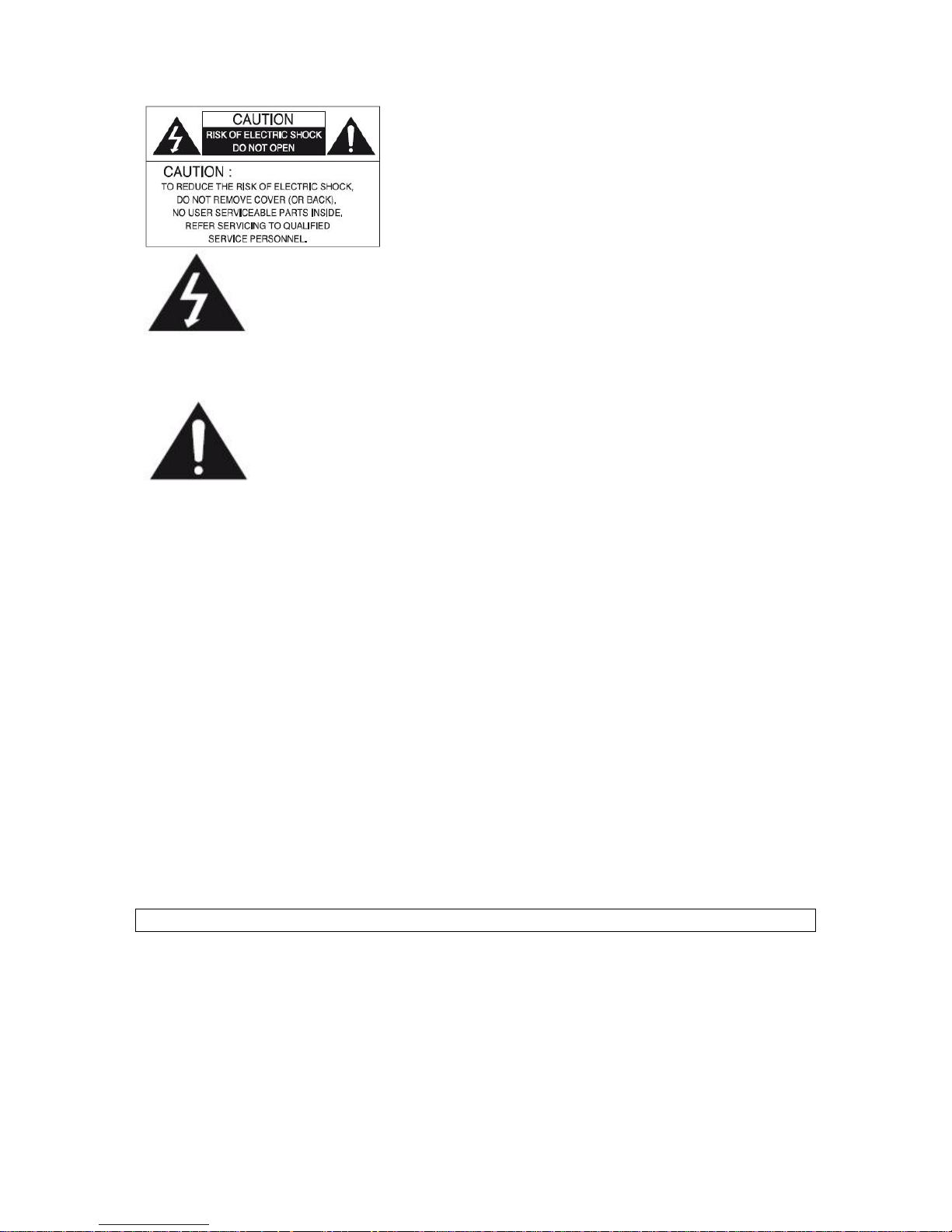
The lightning flash with an arrowhead symbol, within an equilateral
triangle is intended to alert the user to the presence of uninsulated
dangerous voltage within the product's enclosure that may be of
sufficient magnitude to constitute a risk of electric shock to persons.
The exclamation point within an equilateral triangle is intended to alert
the user to the presence of important operating and maintenance
(servicing) instructions in the literature accompanying the appliance.
INFORMATION - This equipment has been tested and found to comply with
limits for a Class A digital device, pursuant to part 15 of the FCC Rules & CE Rules.
These limits are designed to provide reasonable protection against harmful
interference when the equipment is operated in a commercial environment.
This equipment generates, uses, and can radiate radio frequency energy and, if
not installed and used in accordance with the instruction manual, may cause
harmful interference to radio communications.
Operation of this equipment in a residential area is likely to cause harmful
interference in which case the user will be required to correct the interference at
his own expense.
WARNING - Changes or modifications not expressly approved by the
manufacturer could void the user’s authority to operate the equipment.
CAUTION : To prevent electric shock and risk of fire hazards:
Do NOT use power sources other than those specified.
Do NOT expose this appliance to rain or moisture.
This Installation should be made by a qualified service person and should confirm to all local codes.
Page 3

Manual CC 5455IR
3
Warning
The camera requires periodic inspection.
Contact an authorised technician to carry out the inspection.
Stop using your camera when you find it malfunctioning.
If the camera emits smoke or is unusually hot for a long period, a fire may be caused.
Do not install the camera on a surface that can not support it.
If the camera is installed on an inappropriate surface, it may fall and cause injury.
Do not hold plug with wet hands.
It could cause an electric shock.
Do not dis-assemble the camera.
It may result in an electric shock or other hazards.
Do not use the camera close to a gas or oil leak.
It may result in a fire or other hazards.
Page 4

Manual CC 5455IR
4
Contents
NOTICE 5
Important Safeguard 5
Precautions 5
Features 6
Components 7
Names and Functions of Parts 7
Dimensions 8
Installation 9
Cable Connections 10
How to Operate the Bracket 10
Communication Control Connector 11
Control via the RS-485 Interface 11
How to Use the Camera 12
Menu 12
Settings 12
Lens 13
Exposure 14
White Balance 16
BACKLIGHT 17
DNR 18
Day / Night 18
Image Adj. 19
Special 20
EXIT 22
Troubleshooting 23
Specifications 24
Page 5

Manual CC 5455IR
5
NOTICE
Important Safeguard
1. Read Instructions
Read all of the safety and operating instructions before using the product.
2. Retain Instructions
Save these instructions for future reference.
3. Attachments / Accessories
Do not use attachments or accessories unless recommended by the appliance manufacturer as they
may cause hazards, damage product and void warranty.
4. Water and Moisture
Do not use this product near water or moisture.
5. Installation
Do not place or mount this product in or on an unstable or improperly supported location. Improperly
installed product may fall, causing serious injury to a child or adult, and damage to the product. Use only
with a mounting device recommended by the manufacturer, or sold with the product. To insure proper
mounting, follow the manufacturer's instructions and use only mounting accessories recommended by
manufacturer.
6. Power source
This product should be operated only from the type of power source indicated on the marking label.
Precautions
■ Operating
-Before using, make sure power supply and others are properly connected.
-While operating, if any abnormal condition or malfunction is observed, stop using the camera
immediately and then contact your local dealer.
■ Handling
-Do not disassemble or tamper with parts inside the camera.
-Do not drop or subject the camera to shock and vibration as this can damage camera.
-Care must be taken when you clean the clear dome cover. Especially, scratch and dust will ruin your
quality of camera.
■ Installation and Storage
-Do not install the camera in areas of extreme temperature, which exceed the allowable range.
-Avoid installing in humid or dusty places.
-Avoid installing in places where radiation is present.
-Avoid installing in places where there are strong magnetic fields and electric signals.
-Avoid installing in places where the camera would be subject to strong vibrations.
-Never expose the camera to rain and water.
Page 6

Manual CC 5455IR
6
Features
Ultra High Resolution
By adopting a double-speed 410.000 pixel
Sony CCD, the camera produces clear
picture quality with a horizontal resolution of
560 TV lines for color, and 600 TV lines for
B/W.
DNR (Digital Noise Reduction)
The amount of low illuminance noise
has been significantly reduced, and the
signal-to-noise ratio(S/N) as well as
horizontal resolution have been improved,
resulting in a clear and sharp image display
even in the dark.
Wide Dynamic Range /WDR)
The camera delivers clear, high quality
pictures even in backlight, by increasing
exposure in dark areas while decreasing it
in bright areas; a corrected image with clear
details results.
Focus, Viewing Angle & OSD menu
adjustment by RS485 Comm.
Protocol: Peloc D
Baud Rate: 2,400 bps ~ 19,200 bps
Motion Detection
The camera detects motion and generates a
screen message without an external sensor.
Day & Night
The camera identifies whether it is day or night
and automatically switches to the appropriate
mode, depending on its environment. By day,
the camera switches to color mode in order to
maintain optional color. At night, it switches to
B/W mode so as to obtain better pictures
definition.
Photo Sensor & IR LED (77pcs)
IR LEDs are auto switching according to the
control of photo sensor.
Miscellaneous Functions
SYNC (INT/LL), Sense Up, Freeze, Flip (H/VREV), D-Zoom, Sharpness, Motion Detection
and Privacy functions are provided.
OSD
The camera control is convenient by using 7
different foreign language O.S.D.
- NTSC: Korean, English, Spanish, Japanese
- PAL: English, French, German, Spanish,
Ittalian, Chinese
Weather Proof (IP67)
Page 7
Manual CC 5455 IR
7
Components
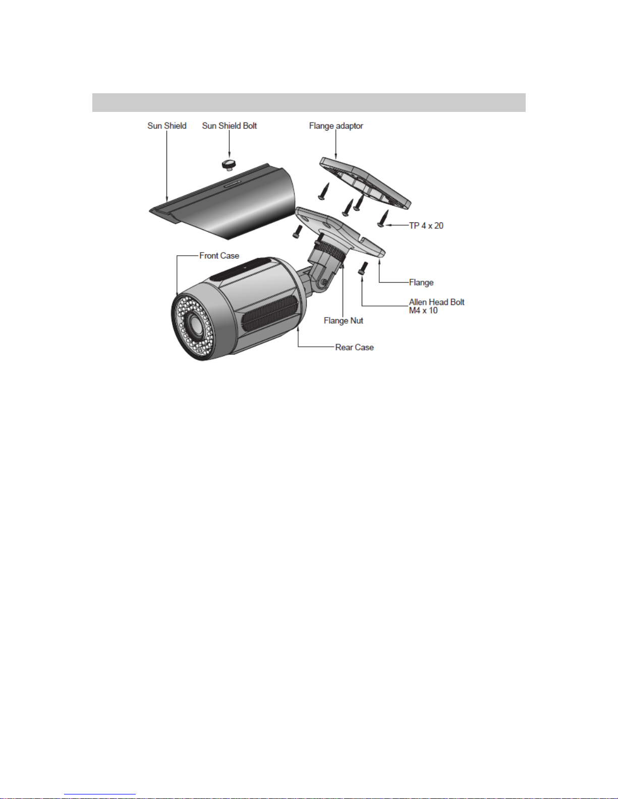
1. Day & Night IR Bullet Camera
2. Screws
3. Allen Head Bolt
4. Wrench
5. Instruction Guide
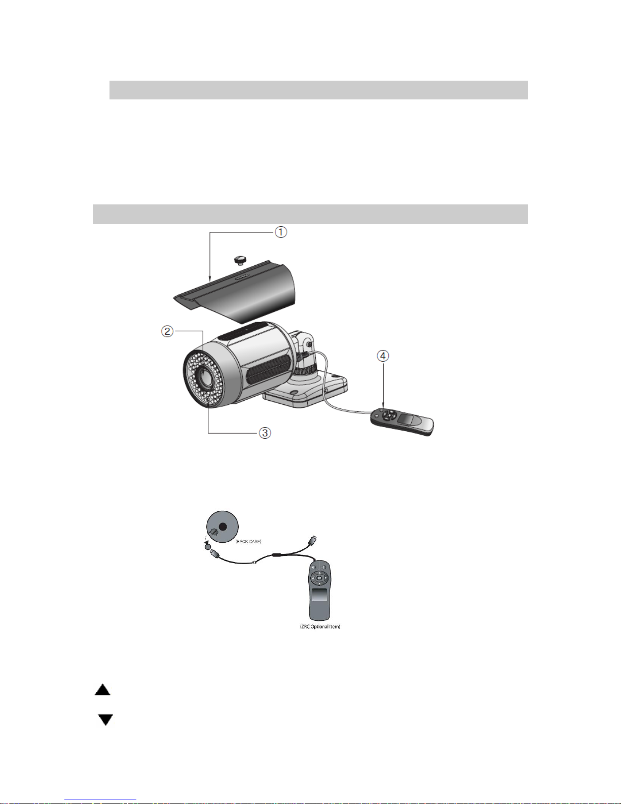
• Names and Functions of Parts
1. Sunshield
2. Lens: Vari Focal Auto Iris Lens
3. Photo Sensor
4. Remote Controller (optional item)
Set: Used to access menu mode and for configuration
:OSD Modus → Cursor up in the menu screen .
Zoom Modus → Zoom control.
:OSD Modus → Cursor down in the menu screen.
Zoom Modus → Zoom control.
Page 8
Manual CC 5455 IR
8
: OSD Modus → Cursor left in the menu screen.
→ Parameter change
:OSD Modus → Cursor right in the menu screen.
→ Parameter change
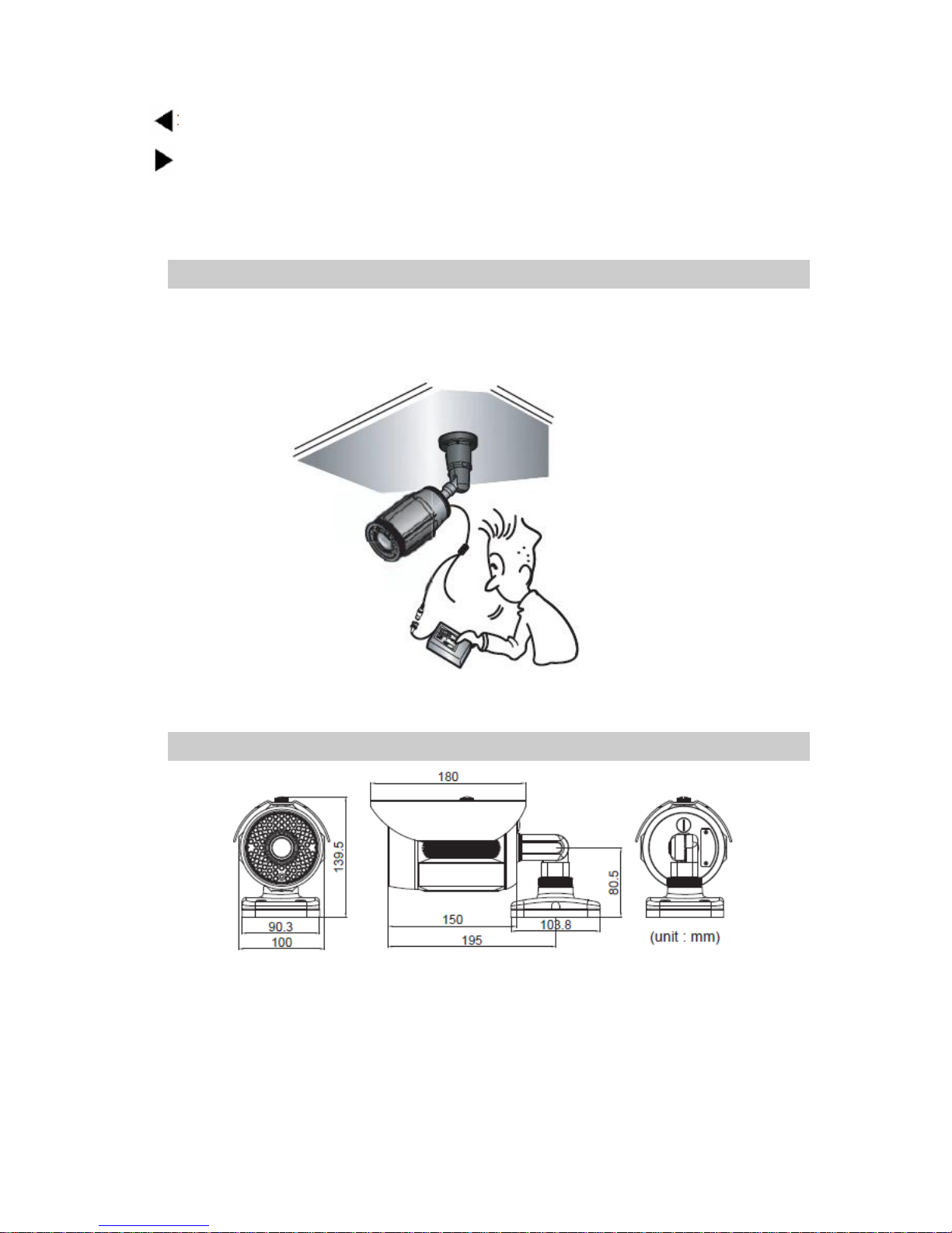
Names and Functions of Parts
Service connector for easy installation of the camera.
- A service monitor can be connected to the camera, allowing the operator to easily atjust camera angles
and settings locally during installation.
Dimensions
Page 9
Manual CC 5455 IR
9
Installation
1. Bracket & Camera Mounting
- Affix the bracket to the mounting surface.
- Use the supplied screws to attach to the mounting surface using the pre-drilled holes in the
bracket.
2. Power Connect & Monitor Impedance
- Use a DC12V/1A regulated PSU or AC24V 1A.
- To avoid fire or shock hazard, always use a CE marked PSU.
- Set the monitor impedance switch to 75Ω. Check the impedance switch if the screen is
blurred.
3. Viewing Angle & Focus Adjustment
- To widen the viewing angle, rotate the Zoom Lever to the Left and to the right to narrow the viewing
angle.
. Rotate the Focus Lever Left or Right to focus the Lens.
4. Sunshield Mounting
- Slide the Sun-Shield over the camera.
5. Remote control & VBS EXTRA
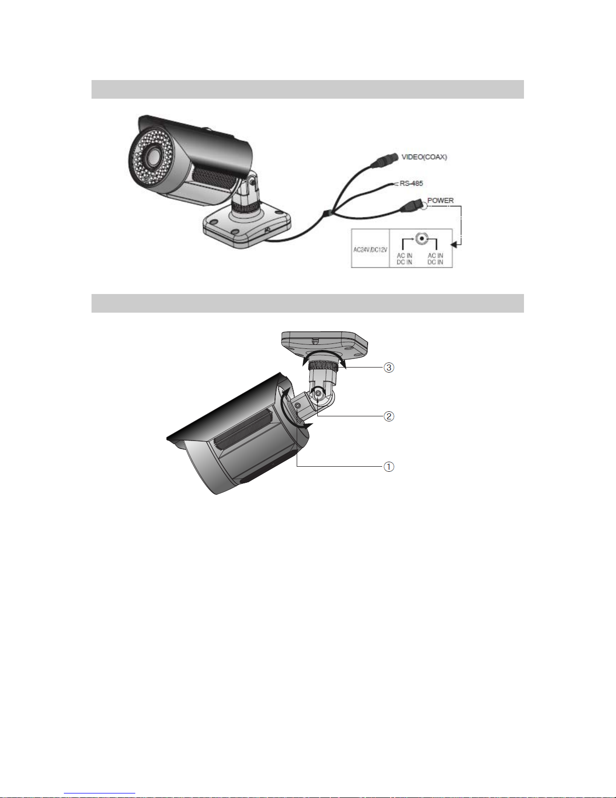
- Remove the cap and connect the connector of the remote control and VBS EXTRA to the
cable socket.
5. When using UTP Cable (Option)
- Connect UTP (Unshield Twisted Pair) wire to UTP output of the camera directly. UTP transmitter is
included in the camera therefore additional UTP transmitter is not necessary.
- UTP receiver is necessary to connect UTP wire to Monitor or DVR.
- When connecting UTP wire, make sure the polarity of the video signal is correct.
- Use UTP wire “CAT 24AWG” to have the best transmission quality.
Page 10
Manual CC 5455 IR
10
Cable Connections
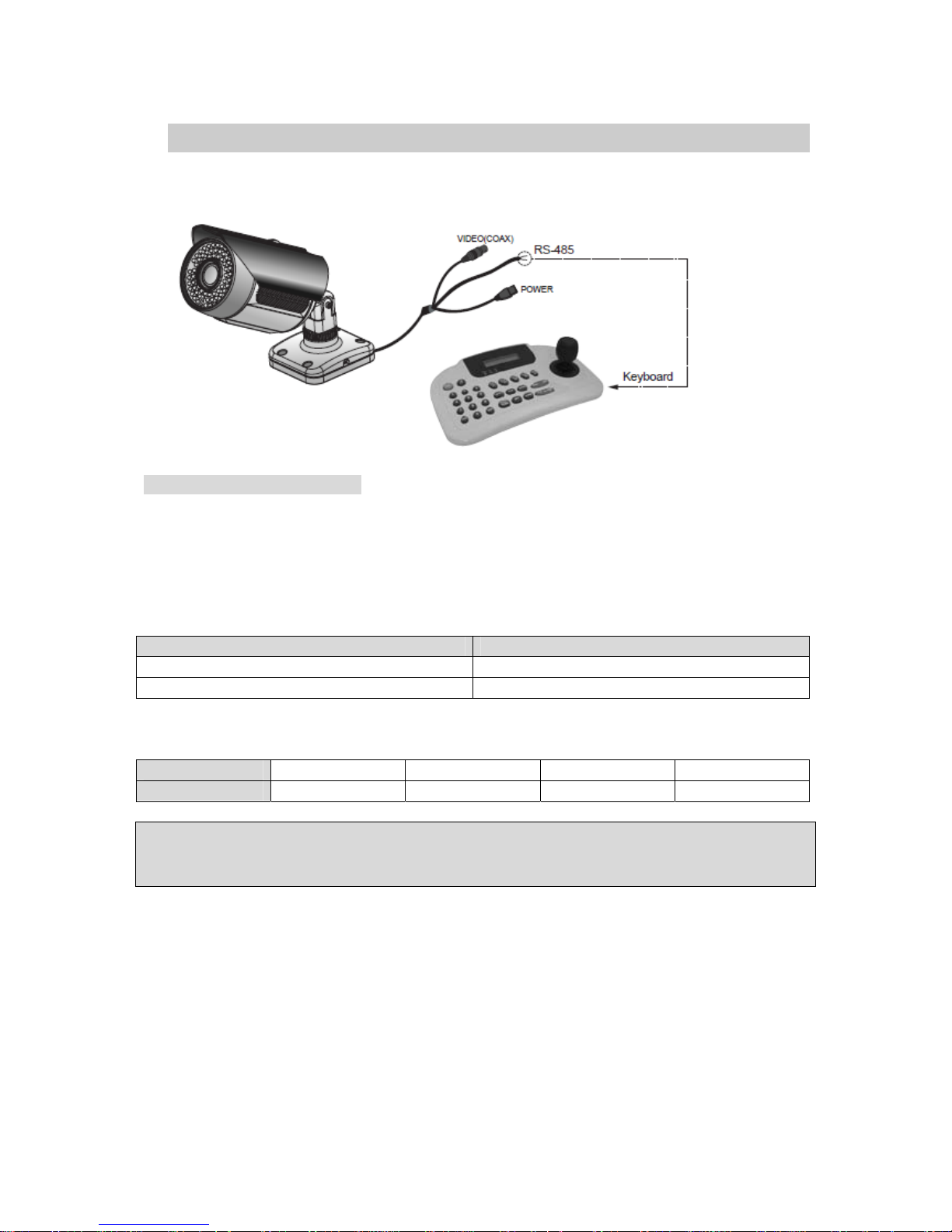
How to Operate the Bracket
1. Loosen the Bolt
Rotate the camera body what want your direction and tighten the Bolt. (360° rotation)
2. Loosen the Bolt
Rotate the camera body what want your direction and tighten the Bolt. (90° rotation)
* Due to the size and weight of this product, it is recommended that that installer hold on to the
mounting bracket junction instead of the camera itself while tightening the bold
(2)
3. Loosen the Flange Nut
Rotate the camera body what want your direction and tighten the Flange Nut. (360° rotation)
Page 11
Manual CC 5455 IR
11
Communication Control Connector
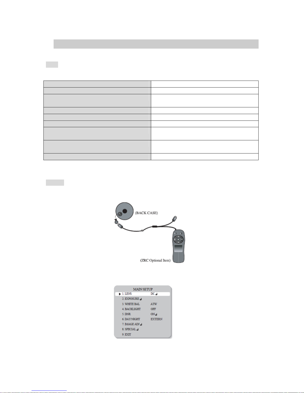
The camera can be controlled by using external controllers. (RS-485 Communication)
Control via the RS-485 Interface
The camera can be controlled by using external controller equipped with RS-485 communications.
- To control using a DVR or keyboard controller
Connect the RS-485 cable (TRX+, TRX-) to the connection port of the 485 control board in the DVR or
controller.
485 Control Board Connection Port RS-485 Control Port
(+) Connection Terminal (TRX+) 485+
( - ) Connection Terminal (TRX-) 485-
* RS-485 communication default initial values.
Irem Camera ID Baud rate UART Mode PET PKT
Iniital value 1 9600 8-None-1 Enable
Note
To control the camera use Pelco-D protocol.
(Go Preset 95: Enters into OSD menu or Set key function)
Page 12
Manual CC 5455 IR
12
How to Use the Camera
Menu
Main Setup Menu
Lens DC Manual
Exposure Shutter AGC Sens-Up Return
White Balance ATW AWCÆSET Manual
Outdoor Indoor
Backlight OFF WDR BLC HLC
DNR ON OFF
Day / Night Color B/W Auto Extern
Image Adjustment Freeze V-REV H-REV D-Zoom
Sharpness Return
Special Function Cam Title Sync Motion Det Privacy DIS
Comm Adj Language Reset Return
Exit
Settings
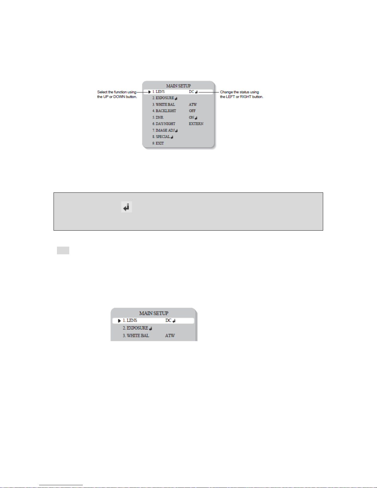
Settings can be made using the 5 buttons located in the camera or the remote controller.
1. Please the SET button to access the main setup mode.
Main setup menu is displayed on the monitor screen.
Page 13
Manual CC 5455 IR
13
2. Select the desired feature using the UP or DOWN button.
Each pressing of the UP or DOWN button moves the indicator to the next or previous features.
Move the arrow indicator to the desired feature item.
3. Change the status of the selected feature using the LEFT or RIGHT button.
4. When completed, move the arrow indicator to 'EXIT' and press the SET button.
Note
Features marked with a have an accessible submenu.
Access the submenu by pressing the SET button.
An item with the - - - icon has no sub-menus available for selection.
Lens
This function is used to adjust the brightness of the screen. .
1. When the SETUP menu screen is displayed on the screen, position the cursor to point to LENS
using the UP and DOWN buttons.
2. Select the type of lens using the Left and Right buttons.
- DC: Select Auto Iris Lens
When DC is selected, you can control screen brightness. The range of brightness control is
between 1 and 70 (40 in case of WDR mode). Adjust the brightness appropriately for optimal
screen brightness.
Page 14
Manual CC 5455 IR
14
Note
Some lenses my not work properly, depending on the settings for Brightness Level.
When Using a Video-Type Auto Iris Lens
1. Check that the ALC adjustment on the lens is appropriate. In general, set it to AV (Average).
2. It may not work properly depending on the installed lens. Set the Level VR of the lens of the optional
value.
3. Set AGC / SENS-UP to OFF and adjust the Lens VR to an appropriate brightness.
4. Adjust the Lens VR, adjust the BRIGHTNESS and then check if the screen brightness changes
properly. Otherwise, adjust the Lens VR again.
- Manual: Select Manual Lens
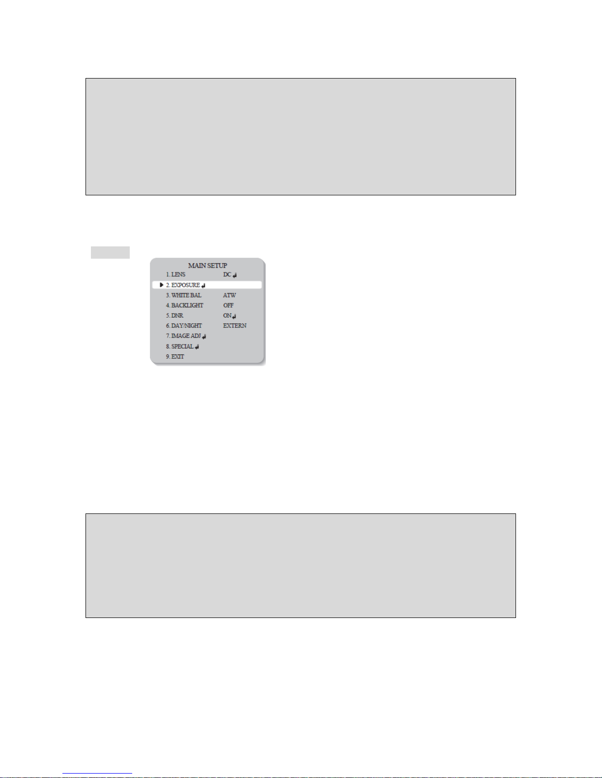
Exposure
1. Press the SET button to access the main setup menu and then position the indicator over
'EXPOSURE' using the UP or DOWN button.
2. Press the SET button to confirm.
SHUTTER: Select either auto or manual shutter.
- A.FLK: Flicker-free mode.
- ESC: Automatic shutter speed setting (optimal).
- MANUAL: Manual shutter speed setting.
Note
- To produce better results with A.FLK, do nor use it in conjunction with the WDR mode on the Backlight
menu.
- When the SHUTTER is set to ESC, and the camera is set to Internal Synchronisation, the picture may
become unstable if the camera faces a bright fluorescent light. Therefore, take care when choosing
the installation position.
- ESC and MANUAL modes are only available together when the lens is set to MANUAL.
- When the SHUTTER is set to MANUAL or A.FLK mode, SENS-UP is disabled.
Page 15

Manual CC 5455 IR
15
AGC (Auto Gain Control) :
The higher the gain level, the brighter the screen – but the higher the noise.
OFF: Deactivates the AGC function
LOW: Allows automatic gain control from 0 to 24dB.
HIGH: Allows automatic gain control from 0 to 42dB.
SENS UP:
When it is night or dark, the camera automatically detects the light level and maintains a clear picture if
this mode is activated.
OFF: Deactivates the SENSE-UP function.
AUTO: Activates the SENS-UP function.
Return:
Select this to save the changes in the EXPOSURE menu and return to the SETUP menu.
Note
• If you press the SET button in AUTO mode, you can adjust brightness by increasing or decreasing the
shutter speed. (X2~X256)
• Note that the higher the zoom level, the brighter the screen, but the more likely it is that an after-image
will appear.
• Although Noise, Spots and Whitish symptoms may occur in SENS-UP operation when the zoom level
is increase, this is normal.
Page 16
Manual CC 5455 IR
16
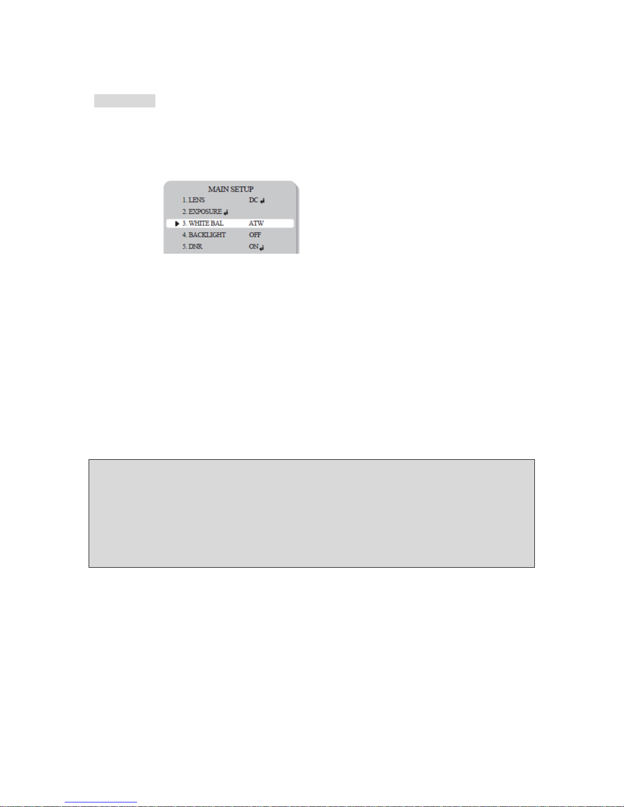
White Balance
Use the White Balance function to adjust the screen colors.
1. Position the cursor to point to WHITE BAL on the SETUP menu screen,
select using the Up and Down buttons.
2. Select a desired mode using the Up and Down buttons.
Select one of the following 5 modes, as appropriate.
ATW: Select when the color temperature is between 1800°K and 10500°K
OUTDOOR: Select when the color temperature is between 1800°K and 10500°K (sodium light
inclusion)
INDOOR: Select when the color temperature is between 4500°K and 8500°K.
AWC:
To obtain the optimum state under the current luminance levels, direct the camera to point
toward a sheet of white paper and press the SET button. If the environment changes, including
the light source, the white balance will require re-adjustment.
MANUAL
Select to "fine-tune" the White Balance manually. Set White Balance first using the ATW or
AWC mode. Afterwards switch to MANUAL mode, fine-tune the White Balance and then press
the SET button.
Note
Under the following conditions White Balance may not work properly.
In such cases, select the AWC mode.
1. When the color temperature of the subject environment has a very high temperature range (e.g. clear
sky, or sunset)
2. When the ambient illumination of the subject is low.
3. If the camera is directed toward a fluorescent light, or is installed in a place where illumination
changes dramatically, the White Balance operation may become unstable.
Page 17
Manual CC 5455 IR
17
BACKLIGHT
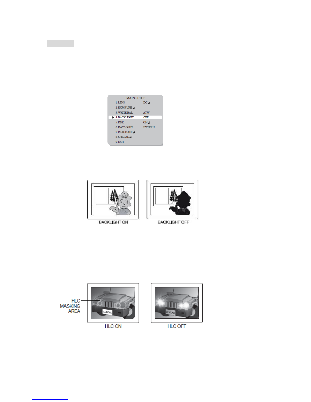
This camera is designed to deliver a clear and distinct image of both subject and background, even
when the subject is backlit.
1. Please position the arrow to point to 'BACKLIGHT' on the SETUP menu by using the UP
and DOWN buttons.
2. Please select the mode you wish to operate by pressing the LEFT or RIGHT button.
WDR : When the image has simultaneous bright and dark areas, the Wide Dynamic Range
makes both areas distinct.
OFF : Deactivates the WDR function.
BLC : Enables the user to directly select an area of a picture to activate and control.
HLC : If there is a high installed in a limited environment such as an apartment parking
garage or gas station entrance, removing the high light makes it possible to view car license
plates efficiently.
- Day: In normal daylight conditions, the HLC is not activated.
- Night: If a high light that is larger than a certain size is present on the screen, remove the high
light to see license plates clearly.
3. Select the desired mode using the Left and Right buttons and press the Set button.
Select WDR to adjust the WDR Limit Select BLC to adjust the area to be
Select Low, Middle, or High. enhanced by the WDR function.
Page 18
Manual CC 5455 IR
18
Note
• The WDR cannot be used when MANUAL mode or A.FLK mode in the 'SHUTTER' menu is selected.
• If the following symptoms occur when WDR is selected, deactivate it.
1. Color of screen changes unnaturally.
2. Noise appears in the brightest part of the screen.
• As the performance of the WDR function can be affected by an area of brightness on the image,
optimise the installation angle to eliminate any bright spots for the best performance.
• If LIMIT is increased, the image may become distorted.
• For the best WDR performance use a DC Iris Lens rather than a Manual Lens.
DNR
This function reduces the background noise in a low luminance environment.
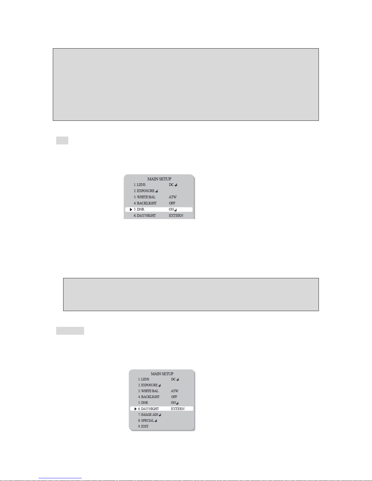
1. When the SETUP menu screen is displayed, select DNR using the Up and Down buttons.
2. Select a desired mode using the Left and Right buttons.
- OFF: Deactivates DNR. Noise is not reduced
- ON: Activates DNR so that noise is reduced.
3. Set the DNR mode to ON and press the SET button. The noise reduction level can now be
adjusted.
Note
- You cannot set the DNR to ON or OFF when the AGC mode in the Exposure menu is OFF.
- When adjusting the noise reduction level in DNR mode, remember that the higher the level is set,
the greater the reduction in noise level, but it also increases the possibility of ghosting.
Day / Night
Pictures can be displayed in either color or black and white.
1. When the SETUP menu screen is displayed, select Day/Night using the UP and Down buttons.
Page 19
Manual CC 5455 IR
19
2. Select the desired mode using the Left and Right buttons.
o Color: The picture is displayed in color.
o B/W: The picture is always displayed in black and white.
o Auto: This camera has an IR Cut-Filter and automatically changes to the appropriate mode
according to lighting levels. To set up the switching time and switching speed for the Auto mode
press the Set button.
o Extern: This mode allows the application of a filter to external signals.
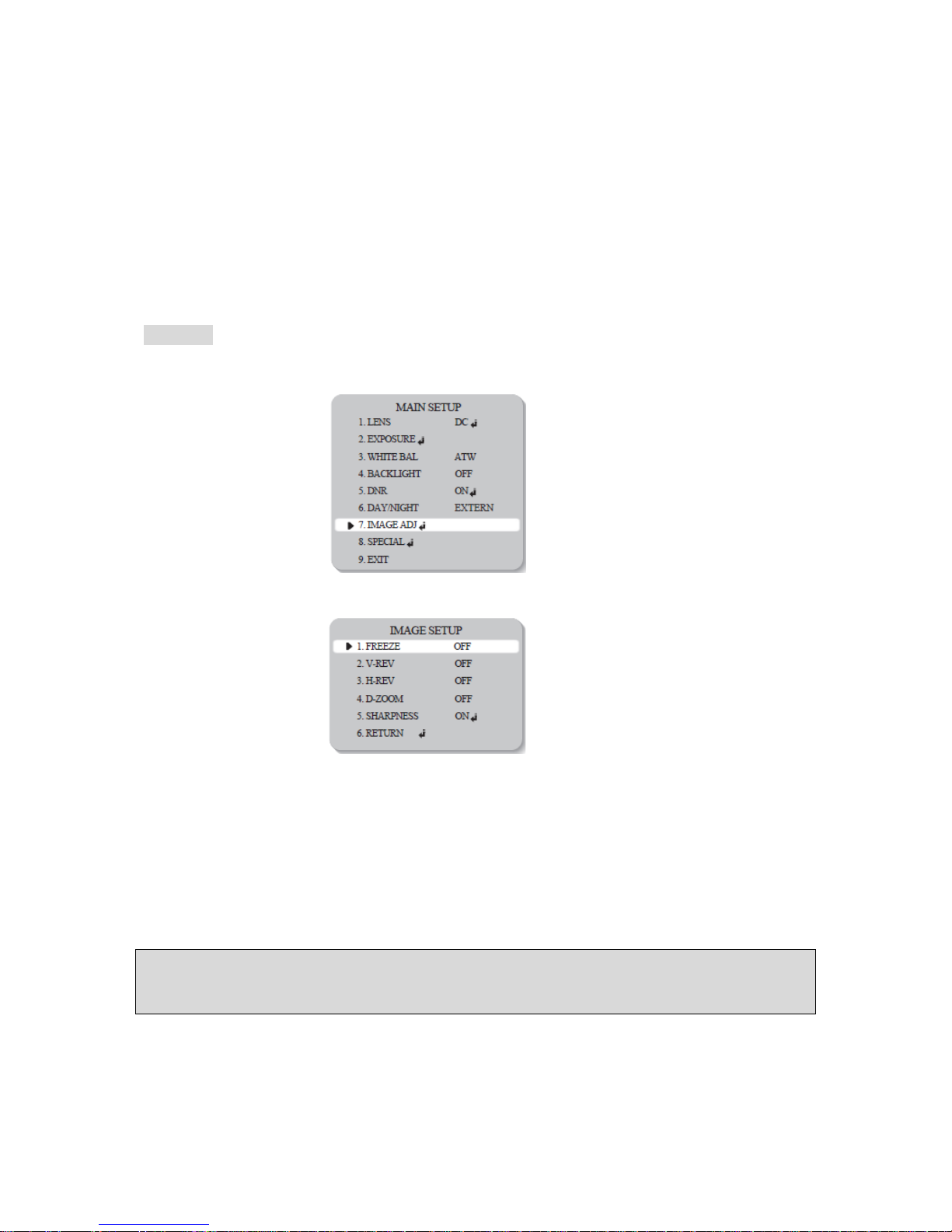
Image Adj.
1. When the Setup menu screen is displayed, select IMAGE ADJ. using the Up and Down buttons.
2. Select the desired mode using the Left and Right buttons.
o Freeze: View and capture a still image
o V-REV: Flips the picture vertically on the screen
o H-REV: Flips the picture horizontally on the screen
o D-Zoom: Digitally zooms, the range is x1~x10
o Sharpness: As this value is increased the picture outline becomes stronger and clearer
o Return: Select this to save the settings for the IMAGE ADJ. menu and to return to the SETUP
menu.
Note
- When H-REV or V-REV is selected, any text in the picture also will be flipped horizontally or vertically.
- If the Sharpness level is increased too high the picture may become distorted, or noise may generated.
Page 20
Manual CC 5455 IR
20
Special
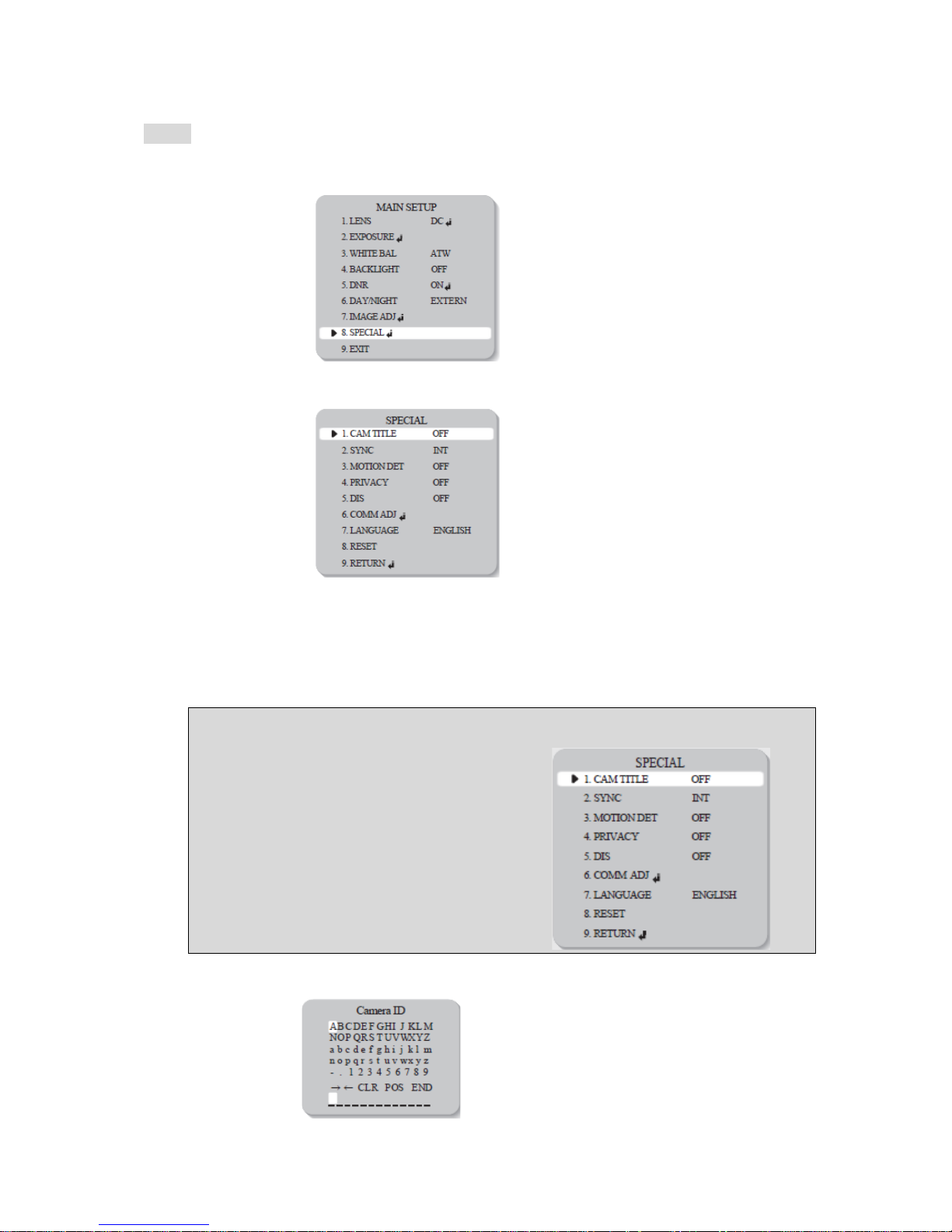
1. When the Setup menu screen is displayed, select SPECIAL using the Up and Down buttons.
2. Select the desired mode using Left and Right buttons.
o Cam Title: If a title is entered, the title appears on the monitor.
- When the Special menu screen is displayed, use the Up and Down buttons to point the cursor
to Cam Title
- Set to ON using the Left and Right buttons.
Note
When the Cam Title menu is OFF, no title will be displayed on
the monitor screen even if one has been entered.
- Press the Set button
Page 21

Manual CC 5455 IR
21
- Use the 4 directional buttons to move to a character, and select it by pressing the Set button.
Repeat this action to enter multiple characters. Up to 15 alphanumeric characters can be used.
Note
If the cursor is moved to CLR and Set button is pressed, all letters are deleted. To edit a letter,
change the cursor to the bottom left arrow and press the Set button. Move the cursor over the
letter to be edited, move the cursor to the letter to be inserted and then press the Set button.
- Enter a title, move the cursor to 'POS' and press the SET button. The entered title appears on
the screen. Select the position to display the title on the screen using the 4 directional buttons
and press the SET button. When the position is determined, select 'END' and press the SET
button to return to the SPECIAL menu.
o Sync: In areas where the supply is 60Hz, multiple cameras using the power synchronisation
function (Line-Lock), without using a synchronisation signal generator.
- INT: Internal Synchronisation Type
- L/L: Power Synchronisation Type, Line-lock
* Press the Set button
* Select a phase between 0 and 359
Note
When using AC power at a 60Hz frequency Line-Lock synchronisation can be used.
When the power is DC 12V, the Sync menu is fixed to the INT mode.
o Motion Det: This camera displays an on-screen message whenever motion is detected.
- When the Special menu screen is displayed, press the Up and Down buttons so that cursor
points to Motion Det.
- Set up function using the 4 directional buttons.
* Sensitivity: Select up to eight MD areas. When the SENSITIVITY value is high, motion
detection sensitivity is increased to recognise small movements.
* Area Mode: Determines whether to use the MD area selected in SENSITIVITY.
* SEL POS: Determines which of the 4 vertices of each MD area is to be used.
* YPOS: Determines the co-ordinates of the vertical axis for SEL POS.
* XPOS: Determines the co-ordinates of the horizontal axis for SEL POS.
* FILL Æ SET: Fills in a selected MD area. Fills in a selected MD area. The color of filling is
sequentially selected as brown, orange, blue, cyan, yellowish green, yellow and red.
* Return: Select this to save the MOTION DET menu settings and return to the SPECIAL
menu.
Note
MD area show only on the Motion Det menu. Therefore, MD areas are not displayed on the monitor
screen.
Page 22

Manual CC 5455 IR
22
o Privacy: Hide an area so that it is not displayed on the monitor.
- When the Special menu screen is displayed, press the Up and Down buttons so that the
cursor points to PRIVACY.
- Set up using the 4 directional buttons.
* AREA SEL: Up to 8 areas are selectable.
* AREA MODE: Determines whether to use the area selected in the AREA SEL, and the size
and position of the area.
* MASK COLOR: Determine area color. Select Grey, Green, Red, Blue, Black or White.
* TRANSP: Determine the transparency of the selected area, the range is from 0 to 3.
* RETURN: Select this to save the PRIVACY menu settings and return to the SPECIAL menu.
o DIS (Digital Image Stabilizer): This function mitigates picture movement caused by external
factors, such as wind.
o COMM Adj. (Communication Adjustment): This function sets up the camera communication
status when controlling the camera through an external device.
- When the Special menu screen is displayed, press the Up and Down buttons so that the
cursor points to COMM ADJ.
- Set up the mode using the 4 directional buttons.
* CAM ID: Determines the camera's identification number (between 0 and 255).
* BAUD RATE: Select 2400/4800/9600/19200/38400/57600 bps.
* UART MODE: Select NONE, EVEN or ODD for the parity bits.
* RET PKT: Determines whether to send a command back to the controller device when a
communication control command is sent to the camera.
* DISP CAM ID: Display the camera title on the top left corner of the screen.
o Language: Select the appropriate menu language.
o Reset: Rests the camera settings to the factory defaults.
o Return: Select this to save the Special menu settings and return to the Special menu.
EXIT
Press the Set button in the EXIT menu to save the current settings and exit the SET menu.
Page 23
Manual CC 5455 IR
23
Troubleshooting
If there are problems in operation, please refer to the items below. If the problem persists, please
contact the agent you purchased this product from.
Problems Troubleshooting
Nothing appears on the screen. • Please check the power connection.
• Please check the video signal line connection.
• Please check and make sure that the auto lens
switch is set to DC (VIDEO) when using a
VIDEO(DC) lens.
The video image is not clear. • Please check if the lens is clean.
Please clean the lens with a clean cloth or brush.
• Please adjust the contrast feature of the monitor.
• Please make sure that the screen is not exposed
directly to a bright light.
Please move the camera if necessary.
• Please readjust the back focus of the camera.
The screen is dark. • Please adjust the contrast feature of the monitor.
• If you have an intermediate device, set the 75 /
Hi-z properly, and check the terminals.
• Please check if an auto iris lens is being used
and adjust the brightness level.
There is a problem with the camera operation.
The camera surface is too hot and black stripes
appear on the screen.
• Please check if an appropriate power source to
the camera complies with the manufacturer's
standard requirement, or if the voltage keeps
changing.
The MOTION DETECTION function is
not working.
• Please check if 'MOTION DETECTION' mode
is turned on.
• Please check if the MD LEVEL is too low.
• Please check the setting of the MD AREA.
Colors are not quite right. Please check the 'WHITE BAL' setting.
The screen is flickering. • Please check if the camera is facing directly into
sunlight or fluorescent light.
• Please check if an auto iris lens is being used.
• Please check the connection of the lens connector
cable.
SENS-UP function is not working. • Please check if the AGC menu is set to the OFF
position.
• Please check if the SHUTTER menu is set to
MANUAL mode.
Page 24
Manual CC 5455 IR
24
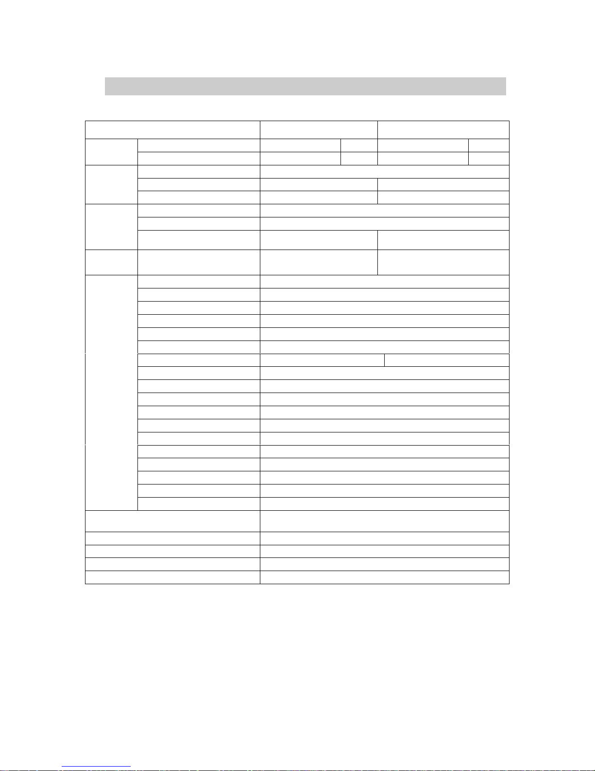
Specifications
ITEM NTSC PAL
Input Voltage
AC 24 V/ DC 12 V DC 12V AC 24 V/ DC 12 V DC 12V
Power
Power Consumption
700mA(AC24V/DC12V) 700 mA 700mA(AC24V/DC12V) 700 mA
Size Sony 1/3“ Vertical Double Density Color CCD
Total Pixels 811(H) x 508(V) 795(H) x 596(V)
CCD
Effective Pixels 768(H) x 494(V) 752(H) x 582(V)
Scanning System 2:1 Interlace
Synchronization INT/LL
sync
Frequency
Horizontal: 15.734 KHz
Vertikal: 59.94 Hz
Horizontal: 15.625 KHz
Vertikal: 50.00 Hz
O.S.D.
Korean, English,
Japanese, Spanish
English, French, German,
Spanish, Itilian, Chinese
WDR 52dB
Back-light Comp. ON / OFF
Resolution Color: 560TVL B/W: 600TVL
S/N (Y-signal) 52dB /AGC Off, Weight On)
Min. Illumination
0,3Lux / F1.2 (50IRE, AGC HIGH, DNR HIGH), 0Lux with IR LED (77pcs)
White Balance ATW/AWC/MANUAL/Outdoor/Indoor (1,800°K~10,500°K)
Electronic Shutter Speed 1/60 ~ 1/120,000 sec 1/50 ~ 1/120,000 sec
Sens-up Auto / Off (Selectable x2 ~ x256)
Gain Control LOW / HIGH / OFF
DNR ON / OFF (1 ~ 32 Level)
Motion Detection ON / OFF (8 Zone, Alarm Output)
Privacy ON / OFF (8 Zone)
V-REV ON / OFF
H-REV ON / OFF
Freeze ON / OFF
Sharpness
ON / OFF (Level Adjustable)
DIS ON/OFF
Electrical
Digital Zoom ON (x10)/OFF
Communication
RS-485 (2400, 4800, 9600, 19200, 38400, 57600 bps selectable)
(Pelco-D Protocol)
Weatherproof IP67
Operating temperature / Humidity -10°C to +50°C / 30% to 80% RH
StoringTemperature / Humidity -20°C to + 60°C / 20% to 90% RH
Weight 1,4 kg
 Loading...