

Page 1

CMP6050
OPERATOR'S MANUAL
Software Version 4.06
At Conviron we develop and implement innovative
and reliable controlled environment solutions.
CMP6050
253652R06
Page 2

CMP6050
OPERATOR'S MANUAL
PLEASE READ THESE INSTRUCTIONS
CAREFULLY AND COMPLETELY
BEFORE OPERATING.
Published by:
CONVIRON
590 Berry Street
Winnipeg, Manitoba
Canada R3H 0R9
www.conviron.com
March 2015
EU declaration of conformity available upon request.
Printed in Canada.
©2015 Controlled Environments Limited.
Conviron is a registered trademark of Controlled Environments Limited. All other trademarks are the property of their respective
owners. Information subject to change without written notice.
Page 3
March 2015 | 253652R06
i
PREFACE
Welcome to the Operator’s Manual for Conviron’s CMP6050 Control System. This Manual
has been developed to assist with the setup and daily operation of the CMP6050. The
Manual is provided to all clients who have purchased a chamber(s) containing the new
CMP6050 control system.
The Manual has been designed to provide sufcient detail for the majority of chamber
congurations, including a structured format that provides step-by-step instructions. Clients will
nd sufcient detail for a typical installation including gures, diagrams, and graphics to operate
the chamber without issue. However, given that many installations are specic to each facility
and that facilities may have unique requirements, additional information or assistance from
Conviron may be required. In such cases, contact information is provided on the following page.
The CMP6050 has a security feature to manage Users' level of access. This feature requires
all Users to be set-up with the appropriate access as determined by the facility manager/
security administrator (up to 3 User ID passwords can be assigned). Once this is completed
(and provided Security is turned on), Users are required to login. This is to ensure that Program
modications are made by authorized personnel only. The Administrator can override all Users
and can access all programming functionality with the exception of features set at the factory.
The CMP6050 offers three password-protected security levels:
• Users (Access Level 1)
• Administrators (Access Level 2)
• Factory (Access Level 3)
Security Access levels associated with various features are identied throughout this manual and
listed in Section 7.0. The CMP6050 is shipped with security features turned Off. This enables
any User to start the chamber and become familiar with the chamber controls without having
to enter a password.
It is recommend that a security Administrator be assigned to administer User
login authority and that security features be added as soon as possible.
This equipment is only to be used by authorized personnel – that is, personnel who have been
trained on the proper use of the equipment and who have read this manual.
The manual incorporates CMP6050 software version 4.06.
Page 4
March 2015 | 253652R06
iii
SERVICE AND TECHNICAL SUPPORT
Conviron welcomes the opportunity to provide assistance and to answer any technical questions
related to the start-up, use and general technical support and troubleshooting of the CMP6050
control system. Before contacting Conviron, please check the following:
• Read this Operator’s Manual in its entirety for information about the feature(s) with
which you are experiencing trouble.
• If you are having a problem using your CMP6050, pay particular attention to
the relevant section and the pertinent information in this manual, and use the
information to diagnose and correct the problem. If the problem persists and/or
you require additional assistance, please collect the following information prior
to contacting Conviron:
• The serial number of the chamber which is located on the rating plate
on the side of the chamber and at the
icon.
• The software version number of the CMP6050. Instructions for
obtaining the CMP6050 software version number are provided in
Section 4.0 Main Status Screen under the Information Icon.
• A description of the problem.
• A description of what you were doing before the problem occurred.
Head office
Technical Services
Conviron
590 Berry St.
Winnipeg, Manitoba,
Canada R3H 0R9
Conviron Technical Services
North America Europe
Toll free +1.800.363.6451 +44.(0).800.032.6422
Telephone +1.204.786.6451 +44.(0).1638.781.731
Fax +1.204.786.7736 +44.1638.741.112
Page 5

March 2015 | 253652R06
v
TABLE OF CONTENTS
1.0 PRECAUTIONS .............................................................................................1-1
2.0 INTRODUCTION TO THE CMP6050 CONTROL SYSTEM...........................2-1
2.1 An Overview of the CMP6050 ................................................................................................. 2-1
2.1.1 Controller........................................................................................................... 2-1
2.1.2 Display ............................................................................................................... 2-2
2.1.3 Software ............................................................................................................. 2-2
2.2 General Specications .............................................................................................................2-3
2.3 Local Control Interface - Programming and Scheduling ....................................................2-3
2.4 Data Logging and Management ............................................................................................ 2-3
2.4.1 Local Data .......................................................................................................... 2-3
2.4.2 Remote Data ..................................................................................................... 2-4
2.5 Alarms ......................................................................................................................................... 2-4
2.6 Security .......................................................................................................................................2-4
2.7 Start-up Delay ........................................................................................................................... 2-4
2.8 Communications ....................................................................................................................... 2-5
2.9 Auxiliary Contacts .....................................................................................................................2-5
2.10 Central Alarm Contact .............................................................................................................2-5
2.11 Optional Accessories ...............................................................................................................2-5
2.12 Process Control Modes: BASIC and VAR ............................................................................. 2-6
2.12.1 STEP Transition ................................................................................................. 2-7
2.12.2 Global Ramp Transition (gRAMP): ................................................................... 2-8
2.12.3 Variable Ramp Transition (vRAMP): ................................................................. 2-9
2.12.4 Disable ............................................................................................................. 2-10
3.0 INITIAL START-UP AND NAVIGATION OVERVIEW .....................................3-1
3.1 Turning the Display On ............................................................................................................ 3-1
3.2 Setting the Time and Date ......................................................................................................3-1
3.3 Other Initial Start-Up Parameters ...........................................................................................3-4
3.4 Navigation Overview ................................................................................................................3-4
3.4.1 LED Indicator Lights ......................................................................................... 3-4
3.4.2 LCD Touch-Screen ............................................................................................ 3-4
3.4.3 Interactive Keys ................................................................................................. 3-5
Page 6
March 2015 | 253652R06
vi
TABLE OF CONTENTS
3.5 Battery ........................................................................................................................................3-5
3.6 Component Stability ................................................................................................................3-5
4.0 MAIN STATUS SCREEN ................................................................................4-1
4.1 Information Icon ........................................................................................................................4-2
4.2 Chamber Status/Alarm Status ................................................................................................ 4-3
4.3 Chamber Selector Icon ............................................................................................................4-3
4.4 Main Menu Bar .......................................................................................................................... 4-4
4.5 Bottom Menu Bar .....................................................................................................................4-5
4.6 Controlled Parameters .............................................................................................................4-6
5.0 PROGRAM SCREEN .....................................................................................5-1
5.1 Program Screen Icons and Locations..................................................................................... 5-1
5.2 Program Screen Main Menu ...................................................................................................5-2
5.3 Accessing the Program Screen ............................................................................................... 5-2
5.3.1 Create Program ................................................................................................. 5-3
5.3.2 Edit Program ..................................................................................................... 5-6
5.3.3 Delete Program ................................................................................................. 5-7
5.4 Schedule Screen .......................................................................................................................5-8
5.4.1 Edit Schedule .................................................................................................... 5-8
5.4.2 Start/Stop ........................................................................................................ 5-10
5.4.3 Clear Schedule ................................................................................................ 5-11
5.4.4 Preferences ...................................................................................................... 5-12
5.4.4.1 Setting the Process Transition Mode – RAMP vs. STEP ..................... 5-12
5.4.4.2 Fan Speed Control and Exhaust Damper Control ............................. 5-13
5.5 Understanding Program Transitions ....................................................................................5-15
5.6 When Ramping Across Midnight is Necessary ...................................................................5-16
5.6.1 gRAMP ............................................................................................................. 5-16
5.6.2 vRAMP ............................................................................................................. 5-17
Page 7

March 2015 | 253652R06
vii
TABLE OF CONTENTS
6.0 ALARM SCREEN ...........................................................................................6-1
6.1 Alarm Screen Icons ...................................................................................................................6-1
6.2 Alarm Overview ......................................................................................................................... 6-1
6.3 RAMP and STEP Mode ............................................................................................................ 6-2
6.3.1 RAMP Mode Temperature Tracking Alarms .................................................. 6-2
6.3.2 STEP Mode - Limit Alarms ............................................................................... 6-3
6.3.3 RAMP and STEP Mode - Alarms and Shutdown ............................................ 6-3
6.4 Setting Alarms ........................................................................................................................... 6-4
6.4.1 When in RAMP Mode (gRAMP or vRAMP) ..................................................... 6-4
6.4.2 When in STEP Mode ......................................................................................... 6-5
6.5 Alarm Status Indicators ............................................................................................................6-6
6.6 Alarm Corrective Action .......................................................................................................... 6-7
6.7 Alarm Types ...............................................................................................................................6-8
6.8 Alarm History ............................................................................................................................. 6-9
6.9 Clear Alarms ............................................................................................................................6-10
7.0 SECURITY SCREEN .......................................................................................7-1
7.1 Security Overview .....................................................................................................................7-1
7.2 CMP6050 Level Access ............................................................................................................7-2
7.3 Security Screen Icons and Locations ...................................................................................... 7-3
7.4 Edit User Screen - Change Password ..................................................................................... 7-3
7.5 Login Security Screen ............................................................................................................... 7-5
7.6 Logout Security Screen ............................................................................................................7-6
8.0 OPTION SCREEN .........................................................................................8-1
8.1 Option Screen - Layout ............................................................................................................ 8-1
8.2 Input Offset (Sensor Calibration) ............................................................................................8-1
8.3 (Chamber) Start-up Delay ........................................................................................................8-2
8.4 Time/Date .................................................................................................................................. 8-3
8.5 Setup ..........................................................................................................................................8-4
8.6 Security On/Off ......................................................................................................................... 8-4
Page 8
March 2015 | 253652R06
viii
9.0 TREND SCREEN ...........................................................................................9-1
9.1 Trend Screen – Key Area Layout ............................................................................................. 9-2
9.1.1 Pan Mode Screen Fields .................................................................................. 9-3
9.2 How to Pan on the Trend Screen ............................................................................................ 9-4
9.3 How to Zoom on the Trend Screen ........................................................................................ 9-4
9.3.1 Zoom Mode Screen Fields ............................................................................... 9-4
9.4 Logged Data – Network ..........................................................................................................9-5
9.4.1 Setting the IP address at the PC (for Windows 7 only) .................................. 9-6
9.4.2 Selecting an IP for the Controller .................................................................... 9-8
9.4.3 Setting the IP address at the Controller ......................................................... 9-8
9.4.4 Downloading logged data via FTP (for Windows 7 only) ............................ 9-10
10.0 SERVICE SCREEN .......................................................................................10-1
10.1 Service Screen Icons ...............................................................................................................10-2
10.2 I/O Status ................................................................................................................................. 10-2
10.3 Scalable Options: ....................................................................................................................10-5
GLOSSARY .............................................................................................................. A
Page 9
March 2015 | 253652R06
1-1
1.0 PRECAUTIONS
The following symbols are used throughout this manual to draw your attention to important warnings,
guidelines and product information. Please take note of their respective meanings.
Hazard Warning Important Information
Dangerous Electrical Current Please Note
Hot Surface Grounding Mark
Slippery Surface Caution, Moving Parts
Please note the following Hazard warnings before operating this equipment:
• This equipment is only to be operated and maintained by authorized personnel - that is,
personnel who have been trained on the proper operation and/or maintenance of the
equipment and who have read this manual.
• If in doubt about safe operation and/or maintenance of the equipment, contact the
responsible party immediately.
• Prior to operating, users should conduct a visual inspection of the equipment and surrounding
area by walking around the unit and checking both inside and outside to ensure no debris or
obstacles are present that could pose a safety hazard. If operators see a potential hazard (e.g.
water accumulating on the oor which could be slippery, an obstruction that would prevent
the door from opening/closing properly) they should take appropriate steps such as alerting
service personnel.
• Before starting, the operator should ensure that all electrical boxes are in the closed
position and that no one is present in the chamber – either servicing or working
within/on the unit.
• Ensure that no one is using or could activate the room remotely during operation or
maintenance activities.
• Avoid water coming in contact with the electrical components, as it presents a risk of
water damage to both high and low voltage electrical components. If you have any
doubt of safe watering practices, contact Conviron.
• When a Schedule is not running, Alarms are disabled! No one other than a single,
designated on-site service technician should be operating the chamber. Altering
output parameters to troubleshoot a chamber, while others are handling mechanical or
electrical systems within the chamber, COULD BE HAZARDOUS AND MAY RESULT IN
PERSONAL INJURY. As such, manipulation of output parameters must be performed
with either a qualied service technician present or via phone support with Conviron’s
Technical Services group.
Page 10
March 2015 | 253652R06
1-2
CHAPTER 1 | PRECAUTIONS
• Qualied trades-people such as electricians, plumbers, refrigeration mechanics, etc.
should perform all work as required by local codes and regulations.
• Central Management™ (CM) is an optional feature. If CM is being used it becomes
inextricably linked to the use of the Controller and therefore, both the Central
Management manual and the Controller Operators Manual must be read and
understood in their entirety prior to operation.
• Working with high voltage will be required when installing this equipment. Do NOT
attempt this work unless you have the appropriate knowledge and experience. Take
appropriate safety precautions and ensure that the building power supply to the
chamber is off prior to installation.
• The main terminal in the control panel has live voltage unless the external breaker is
OFF. Use extreme caution when working in the control panel to prevent injury.
• Water that could come in contact with the electrical components presents a high
voltage hazard. Avoid these conditions. If you have any doubt of safe watering
practices, contact Conviron.
• Controller may come equipped with an optional Uninterrupted Power Supply (UPS)
such that power will remain live for a period of time even if the power supply is turned
OFF. Use extreme caution when working on the control panel to prevent injury. If you
have any doubts as to whether your unit comes equipped with a UPS, contact Conviron.
• Inside the control panel is an independent temperature shut-off device called the
ir33. This ir33 acts as a secondary fail-safe protector that shuts off the chamber if its
temperature limits are exceeded. The ir33 is set by Conviron and is factory protected
(requires Access Level 3). The factory default setting for the ir33 temperature limit is
ten degrees beyond the chamber operating range. The standard operating range of a
chamber is +4˚C to +45˚C while the standard ir33 shut down settings are -6˚C to +55˚C
depending on the size of the chamber, size of the compressor and other factors. Always
verify, when changing the (Alarm) Temperature within the 6050 setup, that the limits
are still within the minimum and maximum operating limits for the Chamber. This will
ensure that the ir33 only triggers in the event that the actual temperature exceeds the
Chamber's minimum or maximum temperature limit by 10 degrees. It will also ensure
that the ir33 does not trigger before a high or low temperature tracking alarm. The ir33
is located inside the control panel where there is live high voltage. Contact Conviron
Client Services for more information or help if necessary.
• Surfaces and lighting may become hot during operation. Always take appropriate
precautions and do not operate if users will remain inside the chamber for more
than a few minutes unless adequate shielding or other safety precautions are taken.
NOTE: HID lamps can cause serious skin burn and eye inammation from short-wave
ultraviolet radiation if the lamp envelope is punctured or broken.
• Operators should note that water may accumulate on the oor which could be slippery
and pose a safety hazard. Always ensure oors remain dry and wear non-slip footwear.
Page 11
March 2015 | 253652R06
2-1
2.0 INTRODUCTION TO THE CMP6050 CONTROL SYSTEM
2.1 An Overview of the CMP6050
The CMP6050 is congured at the factory and offers a wide array of set-up, control and alarm
features to ne tune the conguration on site. The scalability of the CMP6050 accommodates
additional Input/Output ports if necessary. This exibility enables users to add sensors allowing
the CMP6050 to adapt when changing or modifying experiments.
The CMP6050 control system consists of three primary components:
• Controller
• Display
• Control system Software.
2.1.1 Controller
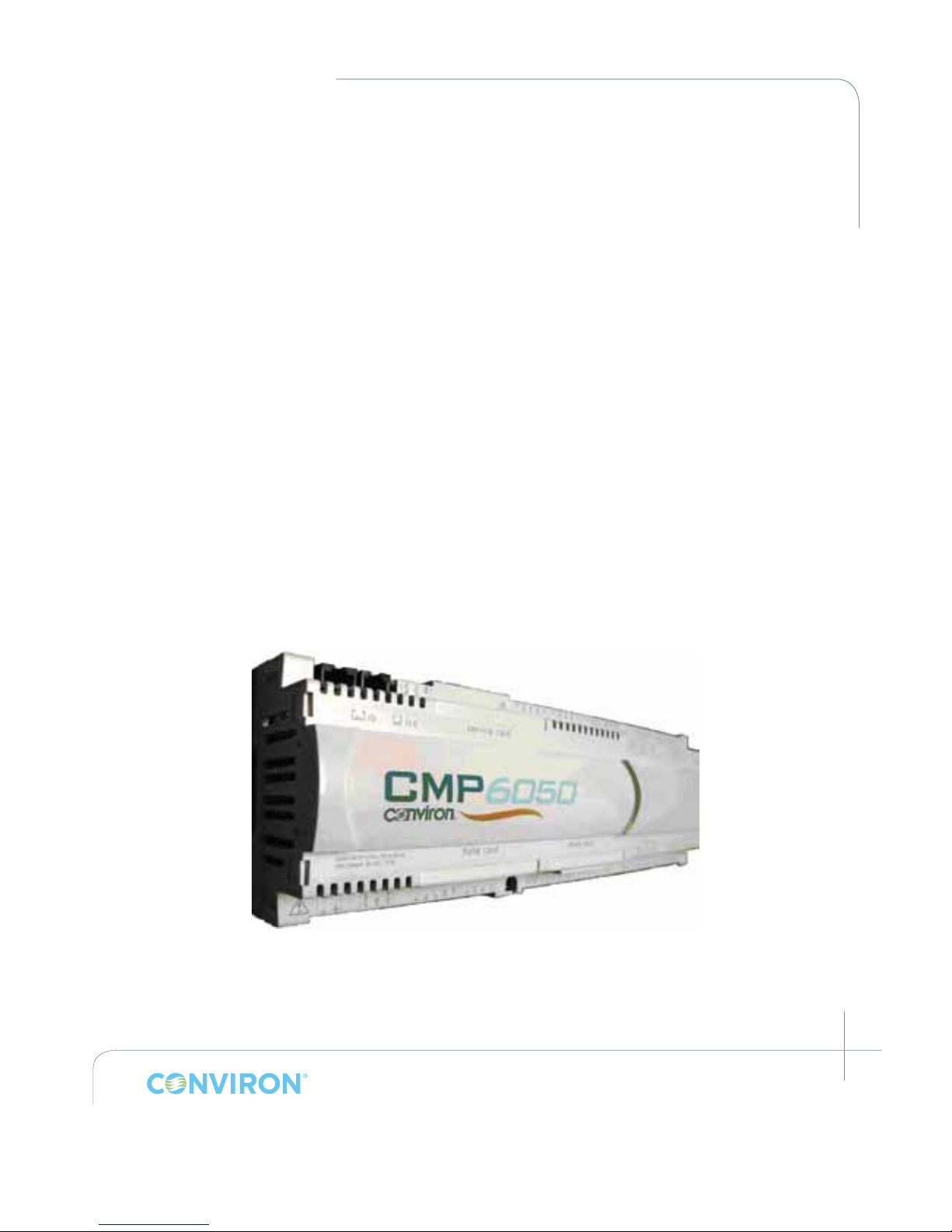
The Controller (Figure 2-1: CMP6050 Controller) is mounted inside the chamber’s control
cabinet and comprises the actual Programmable Logic Controller (PLC). The controller’s job is
to monitor the control parameters and adjust the outputs to coincide with the User’s programs/
schedule. The controller also noties the User with alarms when parameters, for any number of
reasons, deviate outside of specied limits.
Figure 2-1: CMP6050 Controller
Page 12
March 2015 | 253652R06
2-2
CHAPTER 2 | INTRODUCTION TO THE CMP6050 CONTROL SYSTEM
2.1.2 Display
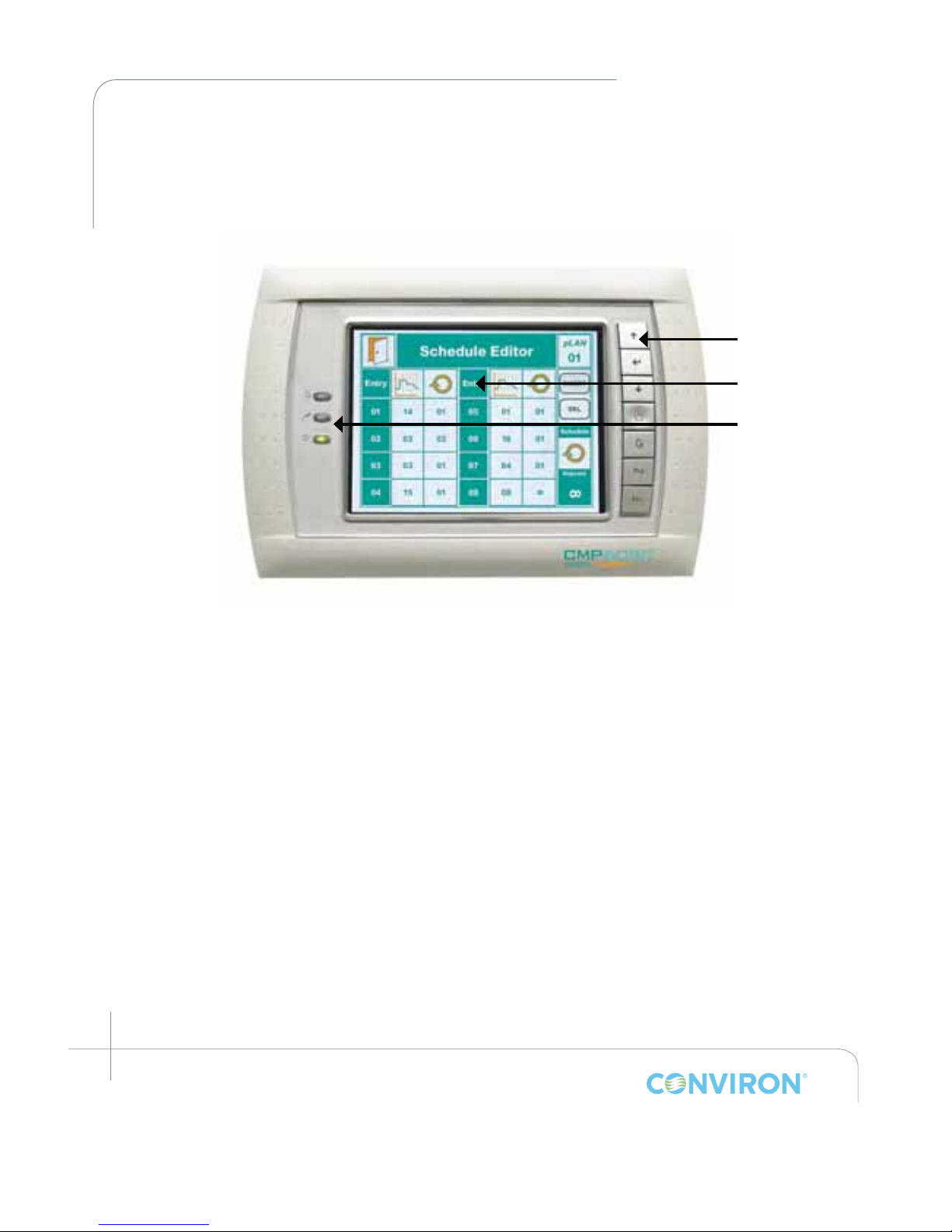
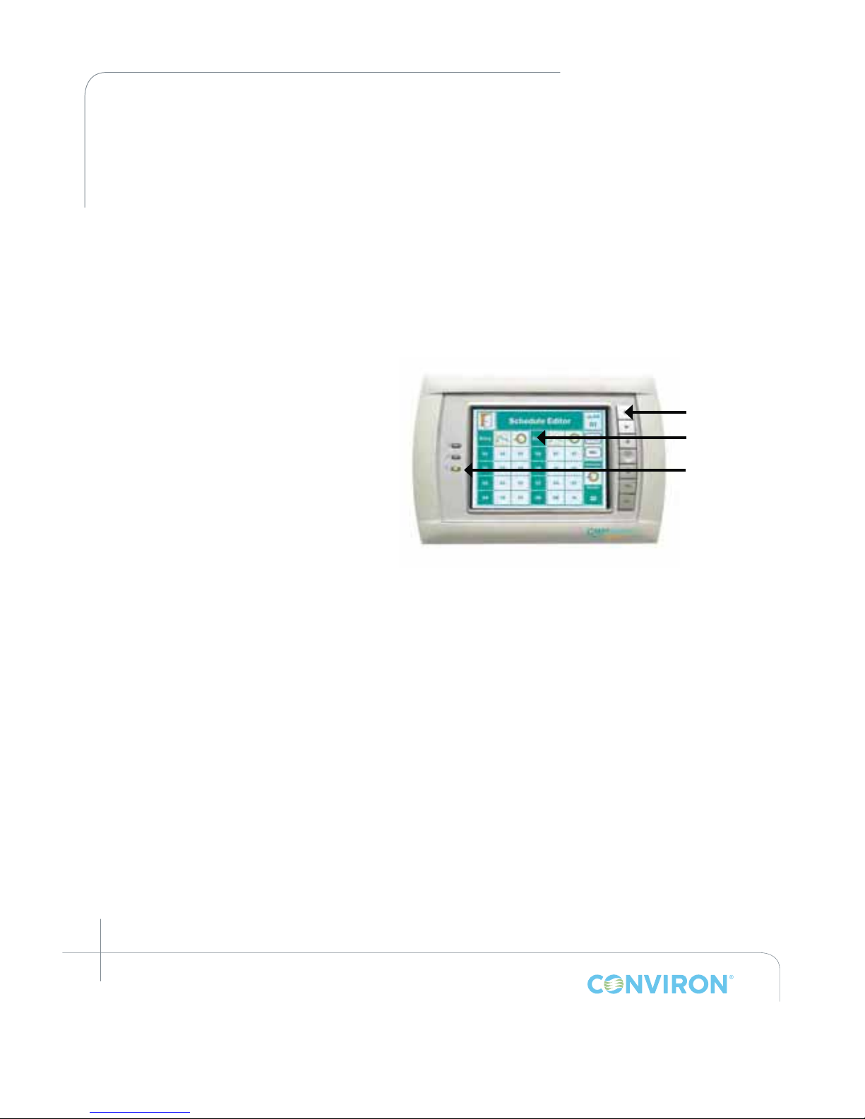
The Display (Figure 2-2) provides the interface to the control system using a LCD (Liquid Crystal
Display) touch screen and push-button keys. There are also three LED indicator lights on the
Display which are used for notifying the User of various conditions.
The touch-screen Display provides access to the following functions:
• Programming and Scheduling
• Alarm
• Security
• Logging
• Graphing
• Service
Information on the touch screen is easy to read because the screen is backlit. Icons are touchactivated and initiate a controller action when they are tapped (or activated with the stylus).
2.1.3 Software
The controller Software is installed into the controller by Conviron prior to shipping and
facilitates interaction with, and control of, the chamber. Like other software products, CMP6050
software carries a version number. Accessing the installed software version number for the
controller is described in Figure 3-2, under the Information Icon.
LED Indicator
Lights
Interactive
Touch-screen
Keys
Figure 2-2: CMP6050 Display
Page 13

March 2015 | 253652R06
2-3
CHAPTER 2 | CMP6050 Operator’s Manual
2.2 General Specications
CMP6050 control system is a robust industrial grade PLC control system designed
for a wide range of controlled environment applications:
• The display uses a 6-inch touch-screen LCD
• Alarms are color-coded directly on the screen making alarm conditions quick to identify
and resolve
• Temperature set-point changes can be set in either STEP or global RAMP (gRAMP)
mode. Humidity, light, and CO
2
set-point changes can be set in STEP mode only
• A default Status screen amalgamates set points and actual conditions into a single, concise
dashboard for easy viewing and improved chamber management.
2.3 Local Control Interface - Programming and Scheduling
• Touch-screen LCD
• Real-time clock programming of control variables
• Can store a maximum of 16 real-time, user-entered programs
• Can store up to 48 timelines per program (with one minute resolution)
• Programs are then entered into the schedule (a sequence of up to 8 program entries) to
create a single day, multi day, seasonal or infinite schedule
• Temperature transitions set as either STEP or gRAMP mode
• Humidity, light and CO
2
transitions are set on STEP mode.
2.4 Data Logging and Management
Log data for the CMP6050 can be viewed two ways: locally at the control system interface, or
remotely via a network-connected PC.
2.4.1 Local Data
• The data available at the local control interface includes main chamber variables –
temperature, humidity, lighting, and CO
2
(if applicable).
• Parameters are all logged automatically by the controller every 18 seconds.
• Data can be accessed with up to five days of history.
• Trend graphs can be viewed directly on the local control interface for both set-point and
actual values (only inputs).
• Zoom and Pan functions provide additional visualization tools allowing the User to precisely
and accurately view and assess the data.
Page 14

March 2015 | 253652R06
2-4
CHAPTER 2 | INTRODUCTION TO THE CMP6050 CONTROL SYSTEM
2.4.2 Remote Data
• The data available remotely is more substantial and includes every input and output
parameter being monitored and controlled.
• Data is logged automatically by the controller every 18 seconds regardless of the number of
parameters. This provides unprecedented data resolution for the User while it also benefits
service personnel.
• Log data is accessed in several ways:
a. A network-connected PC
b. An internet-enabled PC
c. Conviron’s Central Management system (Optional)
2.5 Alarms
• Audible and color-coded visual alarms are provided.
• User-settable absolute alarms for all controlled processes.
• User-settable process tracking alarms for temperature (in gRAMP or vRAMP mode) are
available for the User to determine how tightly to monitor the experiment.
• User-settable process for disabling a controlled process, and thus alarms, at any time
while a program is running.
2.6 Security
CMP6050 security is divided into three password-protected levels:
Users
Access Level 1
Administrators
Access Level 2
Factory
Access Level 3
2.7 Start-up Delay
At start-up, CMP6050 controllers randomly select delay times between 0 and 59 seconds (by
default) to reduce start-up loads after a power failure. This delay time can also be programmed
by the User (reference Section 8-3: (Chamber) Start-up Delay).
Page 15

March 2015 | 253652R06
2-5
CHAPTER 2 | CMP6050 Operator’s Manual
2.8 Communications
Ethernet connectivity is delivered with every controller. The controller is shipped
communications-ready and requires set-up at the facility by a network administrator or other
qualified personnel. (Note: Connectivity is optional on the Adaptis product family).
2.9 Auxiliary Contacts
The controller has 13 auxilliary hi/low digital outputs that can be used to for basic control of
additional equipment.
2.10 Central Alarm Contact
A normally closed dry contact energized by the controller alarm output for connection to a
Building Management System (BMS) or optional auto dialer. When an alarm condition occurs,
the normally closed contact opens, interrupting the circuit from the BMS (or other system) to
indicate an alarm. Only triggered by shut-down alarms (see Section 6.0 Alarm Screen).
2.11 Optional Accessories
AUX: Programmable Output provides an auxiliary switch, terminated in the control panel, for
timed control of automatic watering, nutrient dosing, etc. Auxiliary outputs can be binary (on/off)
and/or time based (01-9999 seconds).
SEN: Thermistor temperature sensors available in 10ft (3m), 30ft (10m) and 50ft (15m) lengths.
Consult Conviron for more information.
ADIAL: An automatic telephone dialing system (autodialer) to notify the User of a chamber
alarm. Note that this requires Conviron’s Central Management™ system, which is sold as a
separate product. Consult Conviron for more information.
VAR: There are two process control modes which govern the way in which chamber
processes (temperature, humidity, light, CO
2
) transition between set points. The default
process control mode set at the factory – called BASIC – is to control temperature in STEP or
global ramp (gRAMP) mode while all other processes are controlled in STEP mode. Clients
do have the option to independently control chamber processes (humidity, light and CO
2
) in
either STEP or variable ramp (vRAMP) mode – called VAR.
Page 16
March 2015 | 253652R06
2-6
CHAPTER 2 | INTRODUCTION TO THE CMP6050 CONTROL SYSTEM
2.12 Process Control Modes: BASIC and VAR
Programs are lists of timelines, with each timeline specifying target set points for all
controlled processes (temperature, light, humidity, and CO2, if equipped). There are three
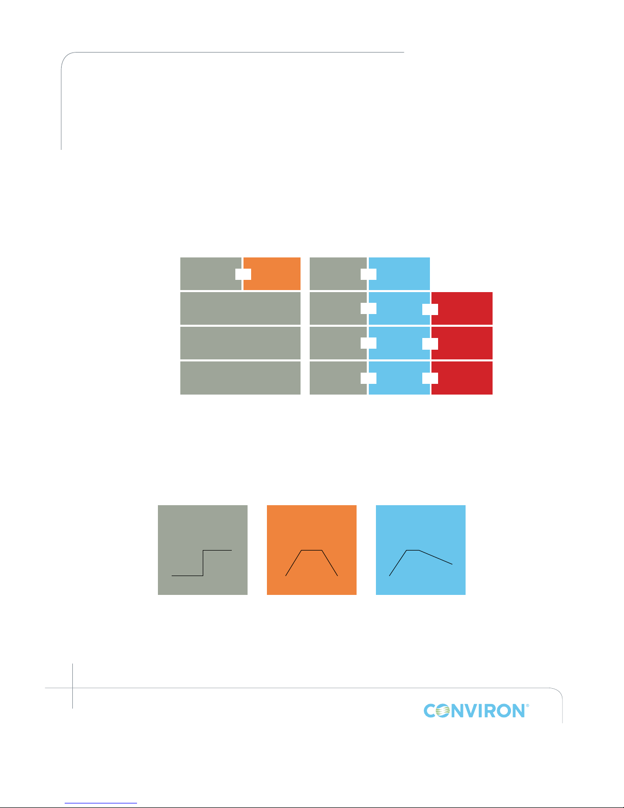
different ways the chamber can transition between target set points: step (STEP), global
ramp (gRAMP) and variable ramp (vRAMP). The control mode (BASIC or VAR) determines
which of these transition modes (step, gRAMP, vRAMP) are available to the User (Figure 2-3:
Process Control Modes, Figure 2-4: Process Transition Modes). Further information about
setting transition modes can be found in Section 5.4.4.1 Process Transition Mode – RAMP
vs STEP.
BASIC
(Standard)
VAR
(Optional)
Temp STEP gRAMP STEP vRAMP
RH STEP STEP vRAMP Disable
Light STEP STEP vRAMP Disable
CO
2
STEP STEP vRAMP Disable
OR
OR
OR
OR
OR
OR
OR
OR
Figure 2-3: Process Control Modes
STEP
vRAMPgRAMP
Process Transition Modes
Figure 2-4: Process Transition Modes
Page 17
March 2015 | 253652R06
2-7
CHAPTER 2 | CMP6050 Operator’s Manual
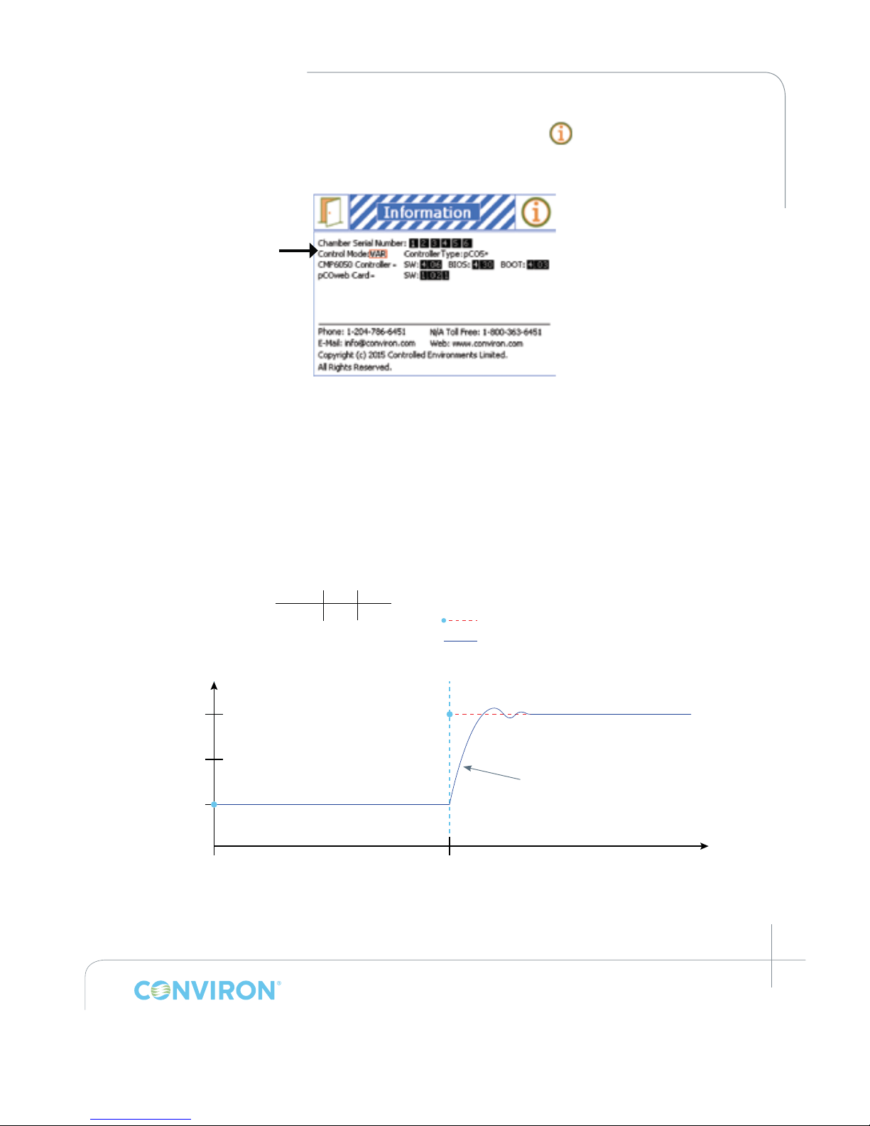
To determine the process control mode, tap the information icon in the upper left corner
of the Main Status screen (see Figure 4-1) to access the Information screen (Figure 2-5).
2.12.1 STEP Transition
• STEP transitions are available for all temperature, humidity, light, and CO2 in both
BASIC and VAR control modes. In this transition mode, the chamber increases or
decreases the process as fast as the chamber is mechanically capable (see Figure 2-6).
Figure 2-5: Information Screen
Process Control Mode
(indicating optional
VAR mode)
Figure 2-6: Example of Step Transition
20
10
15
2
Temp [ºC]
Actual chamber temperature
Time Temp
00:00 10ºC1
Timeline
1
Timeline number
Target set point
9:00
Time [hh:mm]
Example of Step Transition
2 9:00 20ºC
1
00:00
STEP transitions occur as fast as
the capabilities of the heating/
cooling system allow.
Page 18
March 2015 | 253652R06
2-8
CHAPTER 2 | INTRODUCTION TO THE CMP6050 CONTROL SYSTEM
2.12.2 Global Ramp Transition (gRAMP):
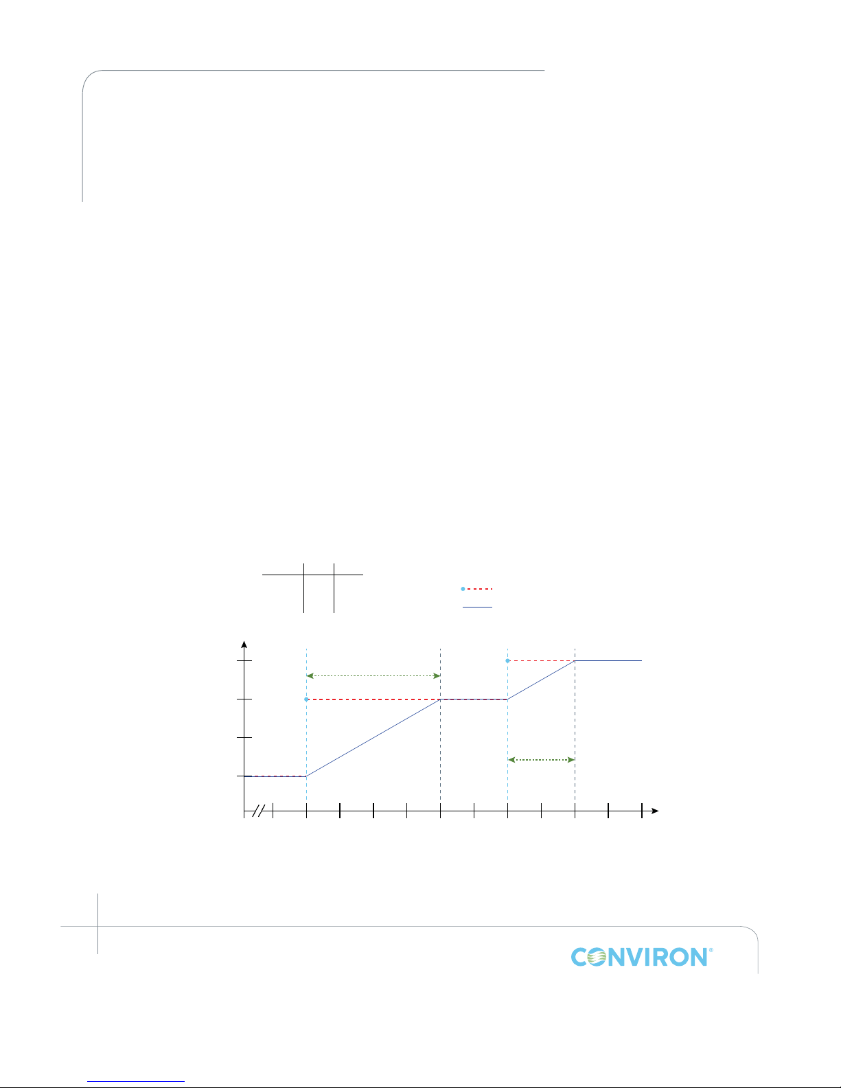
• gRAMP transitions are only available for temperature (see Figure 2-3). In this mode
the chamber increases or decreases temperature at a defined rate selected by the
operator ([x]min/[1°C]), referred to as the global ramp rate (see Figure 2-7).
• Only one global ramp rate is possible at any time. This rate may be changed by
the User, but all temperature transitions in all programs in the schedule will occur
at this global rate. The global ramp rate is set by the operator in the Schedule -->
Preferences screen (see Section 5.4.4 Preferences)
• The default ramp rate set at the factory is 4min/°C, which is the maximum (fastest)
global ramp rate possible.
• When a timeline specifies a new target set point, temperature begins to change
until it reaches that target set point temperature, encounters another timeline with a
different target set point temperature, or the program ends.
• In order to ensure the temperature achieves its target set point at a specific time,
the operator must calculate the amount of time required for the temperature to
reach that target set point from its previous set point based on the global ramp rate.
In the example below, the transition from 10°C to 20°C at 4min/°C requires:
(magnitude of change in process set point values) x (ramp rate in mins per degree)
= (20 - 10) * (4) = 40min. This means that to arrive at 20°C by 9:00, the time line
specifying the 20°C target set point value must occur at 8:20.
Figure 2-7: Example of Global Ramp Transition
2
Actual Chamber Temperature
20
10
15
8:10 9:409:309:209:109:008:508:408:308:20 10:009:50
Time [hh:mm]
25
3
Time required to achieve
target set point value =
(10ºC) x (4min/ºC) = 10 x 4
= 40 min
Time Temp
00:00 10ºC
8:20
1
2
Timeline
1
Timeline number
Target set point
5ºC x 4min/ºC
= 20min
Temp [ºC]
Example of Global Ramp Transition
3 9:20
20ºC
25ºC
1
00:00
Page 19
March 2015 | 253652R06
2-9
CHAPTER 2 | CMP6050 Operator’s Manual
2.12.3 Variable Ramp Transition (vRAMP):
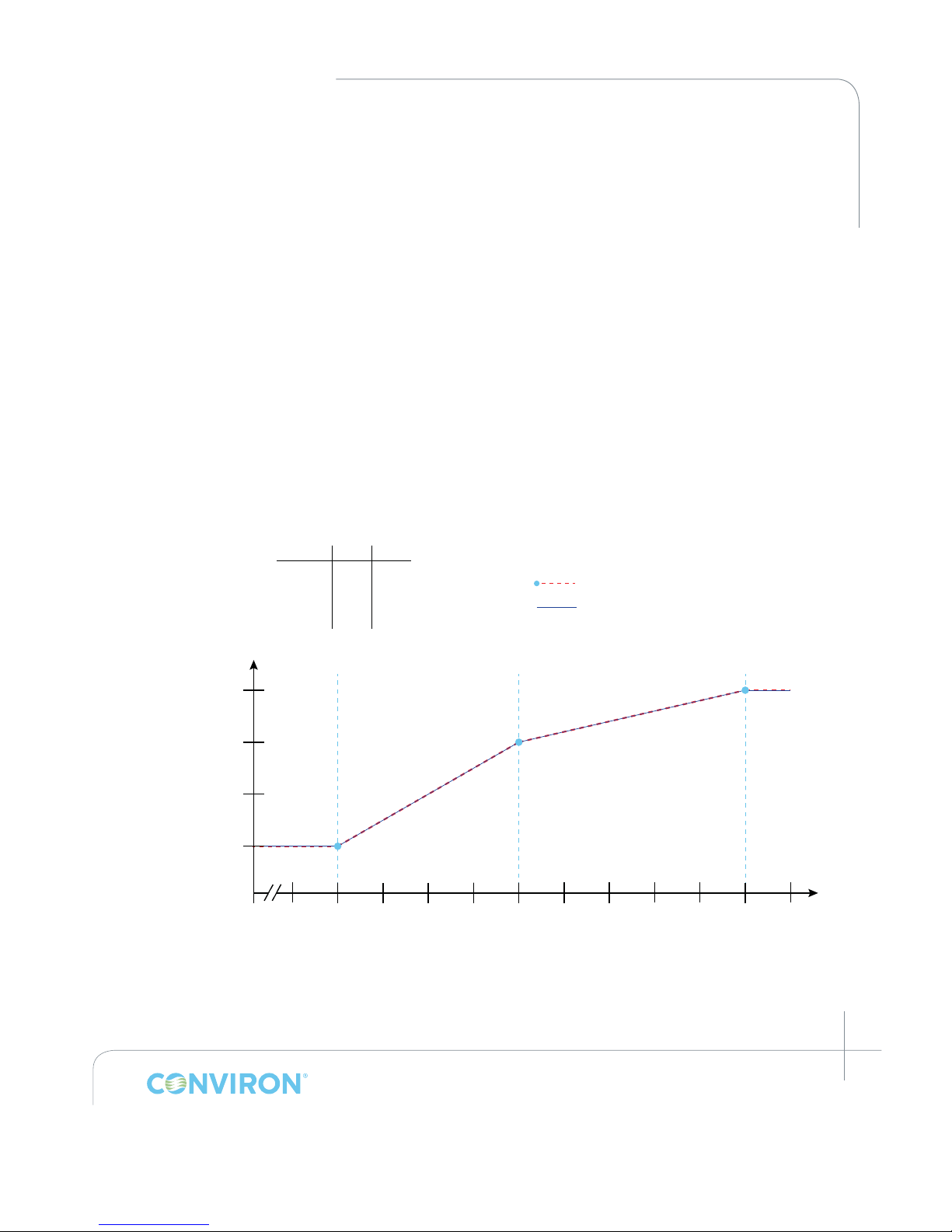
• vRAMP transitions are available for temperature, humidity, light, and CO
2
processes
(see Figure 2-3). In this mode the chamber changes the process at a linear rate
between timeline target set points. This allows the User to program ramp transitions
with many different ramp rates in the same program (see Figure 2-8).
• The ramp rate is determined automatically by the controller based on the amount of
time between timelines and the magnitude of change between process set points
specified by those timelines, eliminating the need for the User to set the ramp rate.
• Each transition requires two timelines: One to specify the start of the transition,
and one to specify the end. When the controller reaches the last timeline in the
program, it will maintain set point conditions specified by that timeline until the
program ends at midnight.
• As with gRAMP, the maximum (fastest) variable ramp rate = 4min/°C. If the User
programs timelines with target set points that exceed this maximum rate, the
controller will default to the maximum ramp rate of 4min/°C for those time lines.
2
20
10
15
7:30 9:008:508:408:308:208:108:007:507:40 9:209:10
Time [hh:mm]
25
3
4
Actual chamber temperature
Time Temp
00:00 10ºC
10ºC7:40
1
2
Timeline
1
Timeline
Target set point value
Temp [ºC]
3 8:20 20ºC
Example of Variable Ramp Transition
4 9:10 25ºC
00:00
1
Figure 2-8: Example of Variable Ramp Transition
Page 20
March 2015 | 253652R06
2-10
CHAPTER 2 | INTRODUCTION TO THE CMP6050 CONTROL SYSTEM
2.12.4 Disable
When a process is set to Disable in control mode VAR, the controller will disable control of
the process and ignore all set points for that process in all programs in the schedule. This
does not affect the values entered in any saved programs, and the process will still trigger
corresponding alarms.
For example: if Humidity is set to Disable, and the low limit alarm had previously been set
to 20% RH, humiditiy values below that limit will still trigger a warning alarm (see Section 6.0
Alarm Screen for more information on alarms).
Page 21
March 2015 | 253652R06
3-1
3.0 INITIAL START-UP AND NAVIGATION OVERVIEW
Now that a general overview of the capabilities of the CMP6050 Control system have been
presented, it’s time for the initial start-up. This section provides instructions on start-up
procedures and general navigation of the CMP6050 control system. Where appropriate,
diagrams, actual screen-shots, and step-by-step instructions are provided.
Do not touch the screen with sharp or pointed objects. Use only the stylus
provided. Use of any other objects on the display screen may damage the
screen and void the warranty.
3.1 Turning the Display On
The CMP6050 is shipped from Conviron with the
latest software installed and with the control system
congured for each specic application. Whenever
the chamber is turned on, the rst screen to be
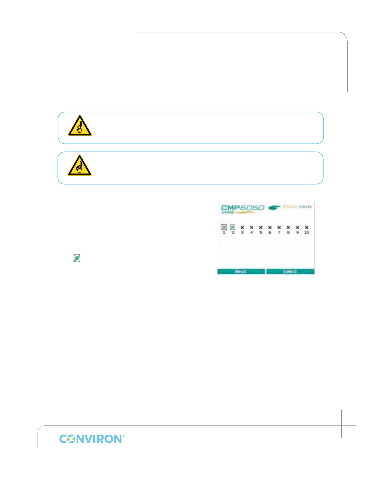
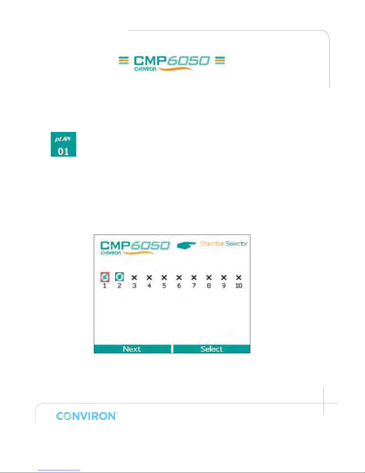
displayed is the Chamber Selector screen shown in
Figure 3-1: Chamber Selector Screen. The Conviron
wave
icon displayed in this screen represents the
chamber(s) that is (are) controllable from the display.
Each display can control up to ten (10) chambers.
If the display has been congured to control more than one chamber, then the Chamber
Selector screen will show additional Icons to represent the additional chambers. The blinking
Icon with the red border represents the chamber currently active with the display.
For example, Figure 3-1: Chamber Selector Screen illustrates that the Display is set up to control
two chambers with chamber number 1 being the currently selected chamber. To select a different
chamber, simply tap the Next tab at the bottom left of the screen with the stylus and then tap
the Select option at the bottom-right of the screen. (To congure additional chambers to be
controlled from the same Display, refer to Section 9-4: Logged Data-Network in this Manual.)
Once the desired chamber number has been selected, the main Status Screen is displayed.
(Figure 3-2: Main Status Screen).
3.2 Setting the Time and Date
The next step required during the initial start-up is to set the Time and Date. Generally speaking,
these steps are required the rst time the control system is used, and thereafter only if/when
these parameters require changing. They will also be required at times of battery replacement
(battery life is approximately 5 years).
Operate your CONVIRON equipment for a few days before introducing any
plant material to acquaint yourself with the equipment’s operation and to ensure
the equipment meets the requirements for your experiments.
Figure 3-1: Chamber Selector Screen
Page 22
March 2015 | 253652R06
3-2
CHAPTER 3 | INITIAL START-UP AND NAVIGATION OVERVIEW
The Time and Date set-up can be accessed in two ways – from the main Status
Screen and also from the Options Screen. For this Section of the Manual,
instructions are provided for accessing these parameters from the Status Screen
only. Section 8.0: Option Screen Icons and Locations covers these features via
access from the Options Screen.
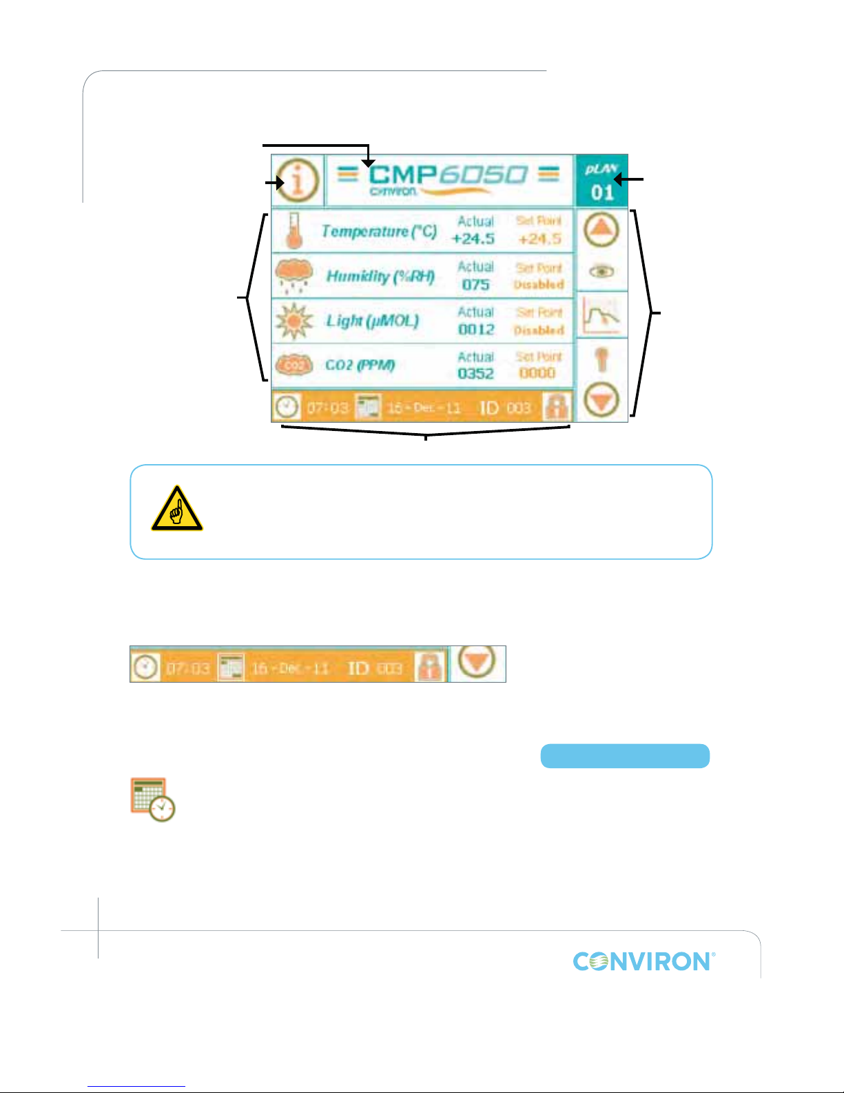
Figure 3-2: Main Status Screen illustrates the Bottom Menu Bar located along the bottom of
the Status Screen. Although this Menu Bar presents four (4) functional Icons, at this stage of
the controller set-up, it is only necessary to set up the proper Time and Date.
3.2.1 Time/Date
Time and Date are essential to the chamber experiment and it is recommended that they be
viewed periodically (daily) to prevent experimental error.
Chamber Selector
Information Icon
Controlled Parameters
Main Menu Bar
Bottom Menu Bar
Chamber status/
Alarm status
Figure 3-2: Main Status Screen
Figure 3-3: Bottom Menu Bar
Access Level 1
Page 23
March 2015 | 253652R06
3-3
CHAPTER 3 | CMP6050 Operator’s Manual
The time is displayed in a 24-hour format (00:00).
The date is displayed in day-month-year format (dd-mmm-yy).
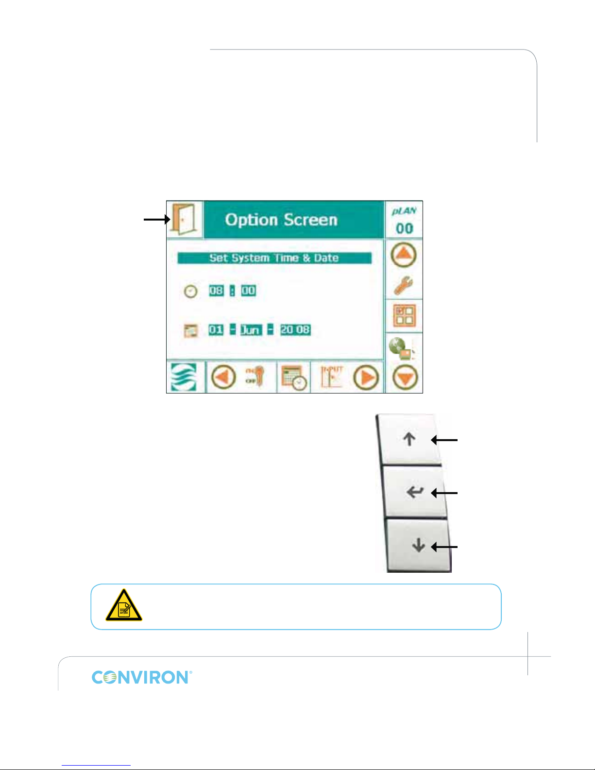
Tap either the Time or Date icon to access the following screen (Figure 3-4: Time and Date Set-up)
and enable editing of the time and date.
1. Press the ENTER key on the right side of the display to activate the Hour eld box.
(There should be a blinking cursor.)
2. Press the UP or DOWN keys to edit the hour.
3. Press the ENTER key to activate the Minute eld box.
4. Repeat Steps two and three for the other eld boxes.
5. Press the ENTER key after entering every eld box when
editing the time and date.
It is essential to follow this process because it locks in the
values entered into the controller. THIS IS MANDATORY.
All values entered are in real-time. Ensure that the time
and date are correct and checked daily to ensure proper
experiment processing.
You can also edit time and date by using the stylus and tapping on the
appropriate numbers on the keypad. Then press the "exit" icon to lock the
values entered into the calendar.
Figure 3-4: Time and Date Set-up
Exit Icon
Figure 3-5: Display Keys
Scroll Up
Enter
Scroll Down
Page 24
March 2015 | 253652R06
3-4
CHAPTER 3 | INITIAL START-UP AND NAVIGATION OVERVIEW
3.3 Other Initial Start-Up Parameters
The Bottom Menu Bar at the bottom of the Main Status screen also includes two other
icons – ID Set-Up and Security Set-Up. These parameters are not discussed in this section
of the Manual because they are more advanced features that are not critical to the initial
basic chamber set-up. That is, they are not required in order for the User to begin using the
chamber. The objective for this section is to provide sufcient information to allow the User
to get the chamber operating with the bare essentials. Note however, that security at this
stage is still disabled.
For information related to the advanced features and options, refer to Section 8.0: Option
Screen of this Manual.
3.4 Navigation Overview
The CMP6050 Display was developed
to be intuitive for the User, while also
accounting for a vast array of interactive
options and display features. To
accomplish this, the Display uses:
• Passive LED Indicator Lights to display
various conditions
• An Interactive LCD Touch-Screen
• A set of interactive Keys
3.4.1 LED Indicator Lights
There are three LED indicator lights on the CMP6050 Display. Their functions are
as follows:
• Top LED – Alarm Condition – Active
• Centre LED – Communication Error (connection between display & controller is lost)
• Bottom LED – Controller On (ashes when running a schedule)
3.4.2 LCD Touch-Screen
The Touch-Screen has two functions – to display information and to facilitate interaction
with the Users. Here, a host of primary and secondary screens are used to provide all the
necessary information required to fully interact with the controller. Sections 4 through 10
of this Manual describe each Screen in detail. Note that the main Primary (default) Screen
is the Main Status screen.
Figure 3-6: CMP6050 Display
Interactive
Touch-screen
LED Indicator
Lights
Keys
Page 25
March 2015 | 253652R06
3-5
CHAPTER 3 | CMP6050 Operator’s Manual
3.4.3 Interactive Keys
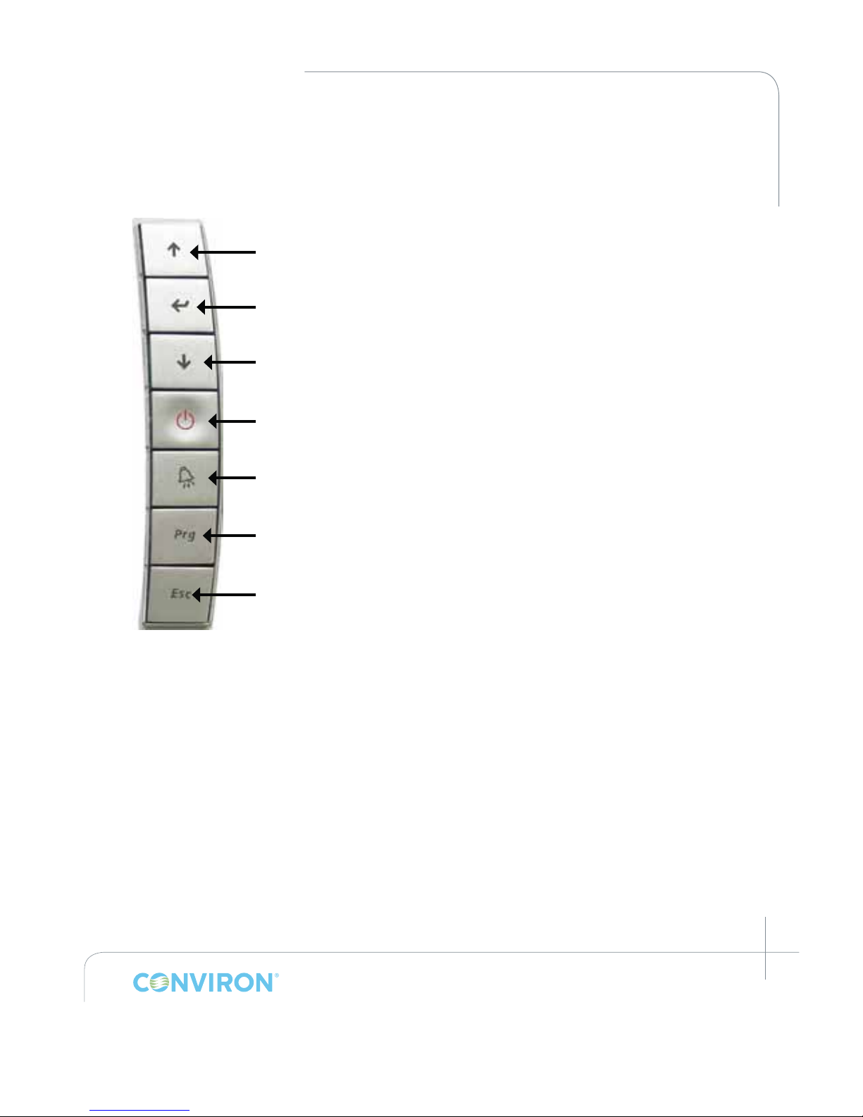
As an alternative to using the stylus with the touch screen, the User can also use the Keys at the
right of the display for many of the interactive functions. Below, a short description is provided
for each Key
.
Up navigation Key
Enter Key
Down navigation Key
OFF Key – This key provides a shortcut to stopping the schedule, when
pressed and held for 3 seconds.
Alarm Key – When an alarm is present, pressing this key will provide a shortcut
to alarm information and acknowledgement.
Program Key – Pressing this key provides a shortcut to the
program screen.
Exit Screen Key – Available on certain screens.
3.5 Battery
The CMP6050 will run off the building power supply, however the controller does have a
rechargeable battery backup to maintain the internal clock. The estimated life of the battery is 6
months and the typical recharge time is < 8 hours.
3.6 Component Stability
The generating conditions of the controller are -25 ˚C to 70 ˚C, 90% RH non-condensing. Storage
conditions are -40 ˚C to 70 ˚C, 90% RH non-condensing. For certain models a separate controller
for the lamp loft is required. Operating conditions for this controller is -10 ˚C to 60 ˚C, 90% RH
non-condensing and storage conditions -20 ˚C to 70 ˚C, 90% RH non-condensing.
Page 26
March 2015 | 253652R06
4-1
4.0 MAIN STATUS SCREEN
At this point in the Manual, instructions have not yet been provided to inform the User how to
start an experiment in the chamber. Before that can be done, it is necessary to become familiar
with the Main Status screen. This section provides an overview of this important primary screen.
Topics covered include:
• Information Icon
• Chamber Status / Alarm Status
• Chamber Selector
• Main Menu Bar
• Bottom Menu Bar
• Controlled Parameters
The CMP6050 control system uses seven (7) primary screens to interact with the various features of
the control system. This Section of the Manual provides an overview of the rst of those screens –
the Main Status Screen. Subsequent sections cover the details of each of the remaining screens.
The Main Menu Bar, which is located at the right hand side of the each of
the seven primary screens, stays constant for each of the seven screens
while the Bottom Menu Bar changes for each of the seven screens.
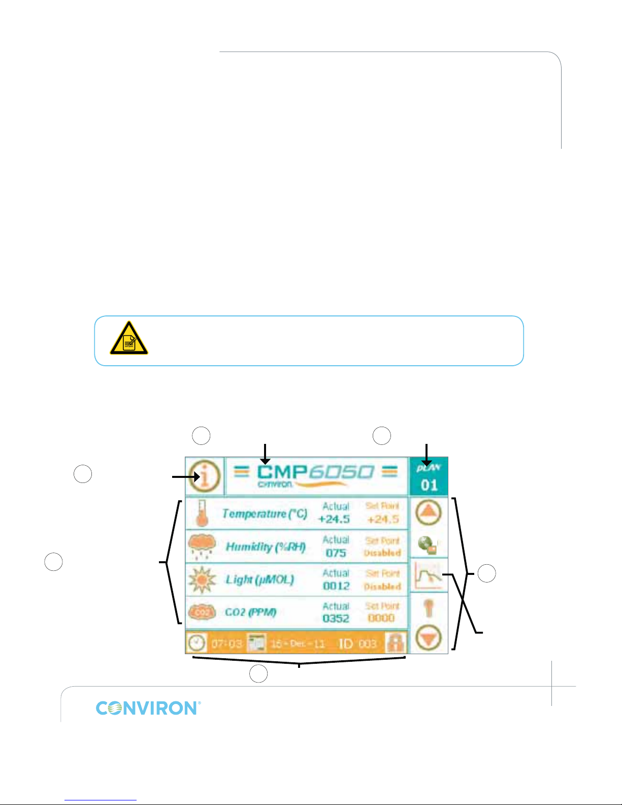
As mentioned earlier, the main (default) control screen is the Status Screen. This is the screen
that essentially acts as 'home base' for the Display. The main areas of the Status Screen are
illustrated in the Figure below:
Figure 4-1: Main Status Screen - Key Area Layout
2 Chamber status/Alarm status
3 Chamber Selector
1 Information Icon/
Schedule Status Icon
6 Controlled Parameters
(configured by chamber) 4 Main Menu Bar
5 Bottom Menu Bar
Actionable Icon
Page 27
March 2015 | 253652R06
4-2
CHAPTER 4 | MAIN STATUS SCREEN
4.1 Information Icon
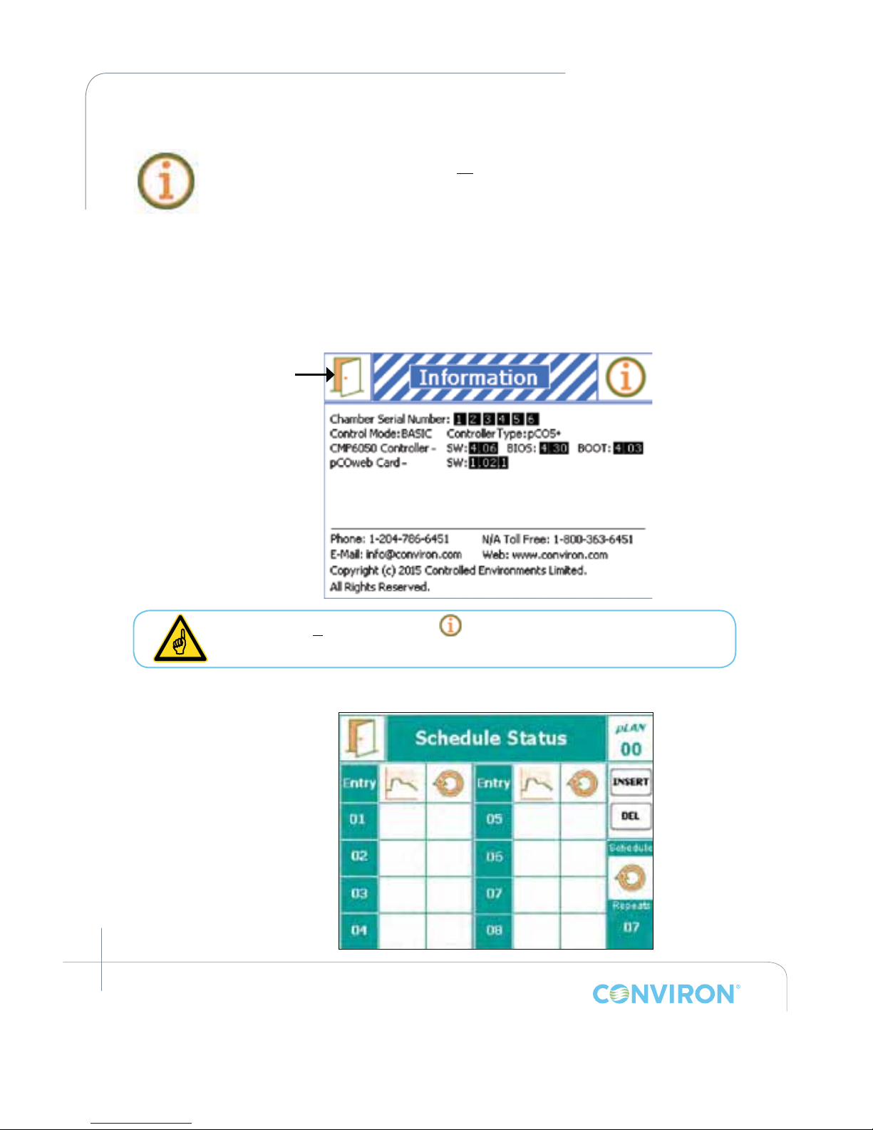
This Icon provides access to two areas of information depending on whether
a schedule is running or not. If there is no schedule running, this Icon provides
access to information related to the controller software, chamber serial number,
and contact information for Conviron's technical assistance. The information is
important for knowing, for example, what version of controller and what version
of software is loaded on the controller or what ramping style your chamber is
running (BASIC or VAR, see section 2.10 Optional Accessories). This information
is not necessarily required on a daily basis but rather during service and/or
troubleshooting activities. Activating this Icon using the stylus launches the
following screen of information. Tap the
Exit icon (top left corner) to return to the Main status screen.
If a schedule is running, then the icon launches a Schedule Status screen
which provides details about the running schedule. See below.
4.2 Chamber Status/Alarm Status
Figure 4-2: Information Icon Screen
14
02
03
01
16
04
01
02
01
01
01
01
01
05
0202
Figure 4-3: Schedule Status Screen
Exit Icon
Page 28
March 2015 | 253652R06
4-3
CHAPTER 4 | CMP6050 Operator’s Manual
This Icon provides information related to the chamber status and the alarm status. Under certain
conditions, this Icon will blink with certain color combinations. Each color combination has a
dened meaning which graphically represents the status of the chamber and alarm conditions.
Refer to Section 6.0 Alarm Screen for more details on alarm functionality.
4.3 Chamber Selector Icon
The CMP6050 control system was designed to enable a single Display to control
up to ten (10) chambers. This Icon allows the User to select which of the chambers
to control with the Display. Note that each additional chamber requires set-up and
conguration. Adding chambers to the Display is covered in Section 9.4 Logged
Data – Network of this Manual. The Figure below presents the screen image
displayed when the Chamber Selector Icon is activated.
To return to the Main Status Screen, tap the Select at the bottom of the screen. Note that in
Figure 4-4: Chamber Selector Screen, the Display has been congured to control 2 chambers.
Chamber no. 1 is the active chamber (red border around icon). To activate a different chamber,
simply tap the Next tab and then tap Select.
Figure 4-4: Chamber Selector Screen
Page 29
March 2015 | 253652R06
4-4
CHAPTER 4 | MAIN STATUS SCREEN
4.4 Main Menu Bar
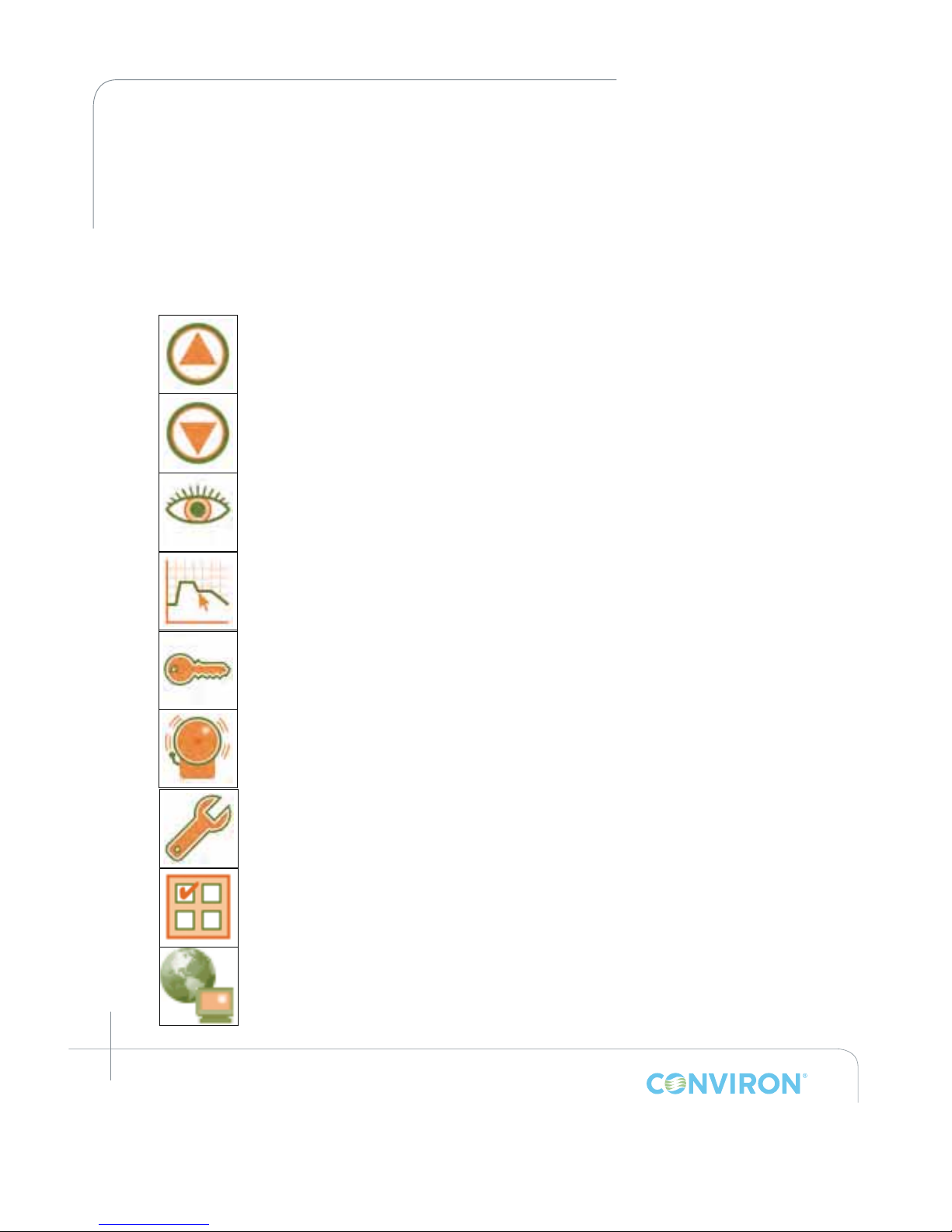
The Main Menu Bar remains constant on all seven of the Primary Screens. This Main Menu
Bar contains a total of nine (9) Icons, seven of which represent the seven Primary Screens and
two of which represent Navigation Icons – one for scrolling up and one for scrolling down.
Note that the Main Menu Bar displays only three (3) Primary Screen Icons at a time. The centre
Icon is actionable, while the other two (non-actionable) Icons displayed on either side of the
actionable Icon are simply there to indicate the next and previous consecutive Icons. The Up
and Down Icons are used for scrolling through the seven Primary Screen Icons.
Navigation Icon – Scroll Up
Navigation Icon – Scroll Down
Status Screen (Refer to Section 4 for greater detail)
Program Screen (Refer to Section 5 for greater detail)
Security Screen (Refer to Section 7 for greater detail)
Alarm Screen (Refer to Section 6 for greater detail)
Service Screen (Refer to Section 10 for greater detail)
Options Screen (Refer to Section 8 for greater detail)
Optional add on screen for increased functionality. Contact Conviron for
additional information.
Page 30
March 2015 | 253652R06
4-5
CHAPTER 4 | CMP6050 Operator’s Manual
4.5 Bottom Menu Bar
The Bottom Menu Bar is dynamic which means it changes depending on the screen being
displayed. The Icons displayed in the Bottom Menu Bar for each primary screen duplicate the
Icons displayed in the main interactive area for each screen. They are duplicated simply for ease
of use allowing Users to choose their preference. Because this section of the Manual pertains to
the Main Status Screen, the Bottom Menu Bar for that screen only will be described here.
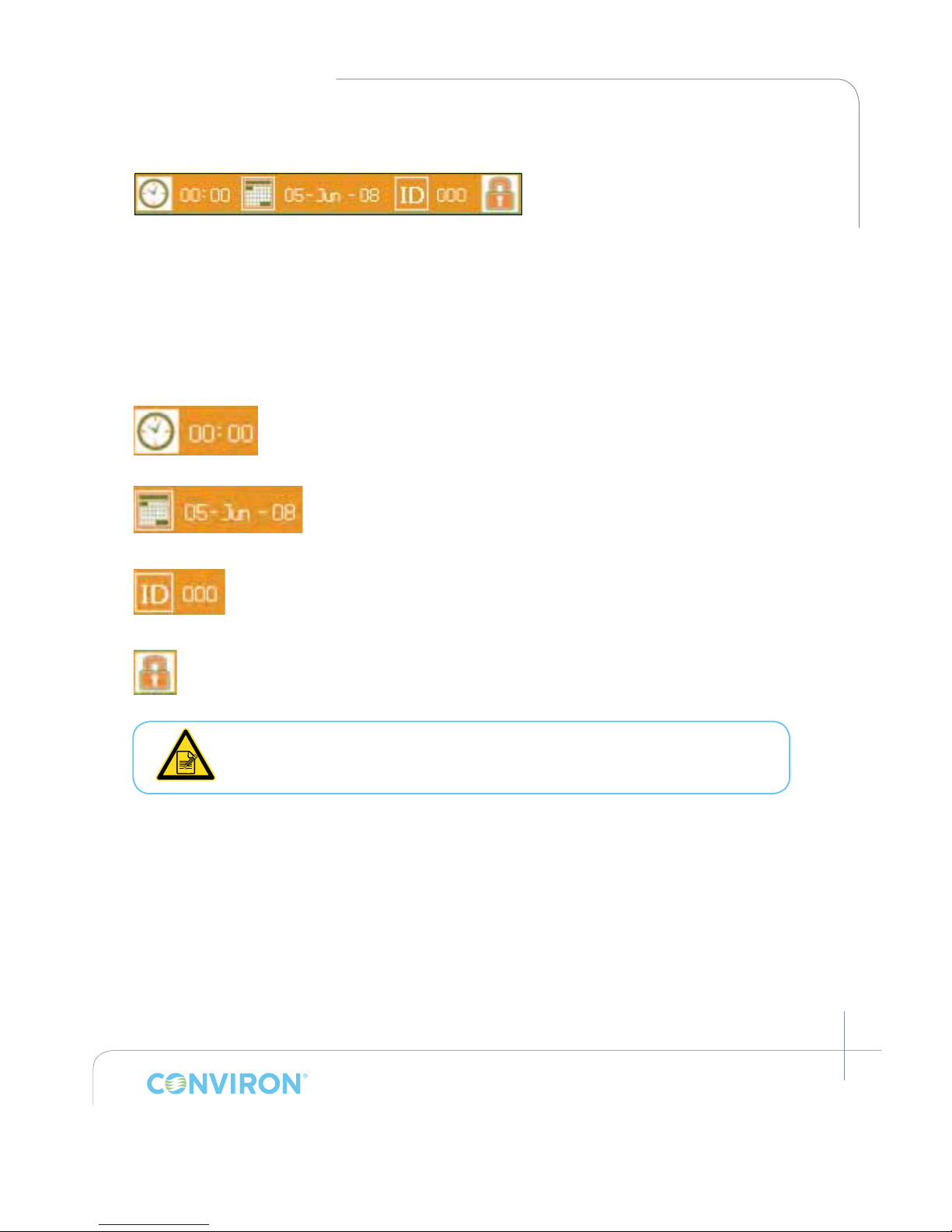
There are a total of four (4) Icons used in the Bottom Menu Bar for the Main Status Screen.
These are described as follows:
Time Icon – used to display the current time. Tapping the Icon launches the
Set System Time and Date screen. (Refer to Section 3.2 Setting Time and
Date for greater detail on this subject)
Date Icon – used to display the current date. Tapping the Icon
launches the Set System Time and Date screen. (Refer to Section 3.2
Setting Time and Date for greater detail on this subject)
ID – used to display the Network Conguration for the controller. (Refer to
Section 9.4 Logged Data – Network for greater detail on this subject.)
Security Login Icon – used to display the Security Screen for the controller. (Refer to
Section 7.5 Login Security Screen for greater detail on this subject)
The Time and Date icons were already used to set the Time and Date in
Section 3.2 of this Manual. Instructions for setting the ID and Security are
covered in Section 7.
Page 31
March 2015 | 253652R06
4-6
CHAPTER 4 | MAIN STATUS SCREEN
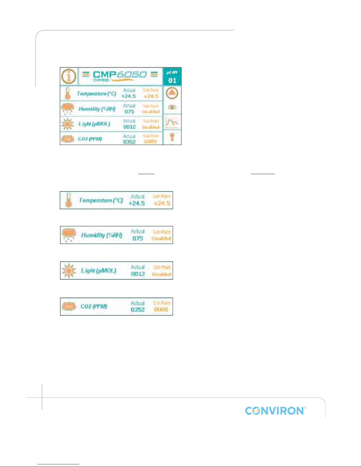
4.6 Controlled Parameters
This area of the Main Status Screen is
reserved for displaying the controlled
parameters (i.e. Temperature, Humidity,
Lighting, and CO
2
). The parameters
actually displayed depend on several
factors including the chamber design and
the conguration set-up of the controller.
For example, only some chambers come
equipped with CO
2
control and therefore
not all chambers will display CO
2
as a
Controlled Parameter.
Figures displayed in the Controlled Parameters area of the screen include the actual value
and the current program set-point value for each parameter. These gures are displayed
in two columns – one for the actual values (green font) and one for the set-point values
(orange font).
The Temperature parameter displays the
temperature in degrees Celsius only.
The Relative Humidity parameter (if applicable)
displays the relative humidity in %RH. This
parameter is valid only if the chamber is
equipped with humidity control.
The Lighting parameter displays the light
intensity in one of several ways – banks;
percentage of full power; or unit micromoles.
The CO2 / Auxiliary parameter displays the
parameter in one of several ways – For CO
2
concentration - in PPM: For an Auxiliary on/off
event – On or Off.
Page 32
March 2015 | 253652R06
5-1
5.0 PROGRAM SCREEN
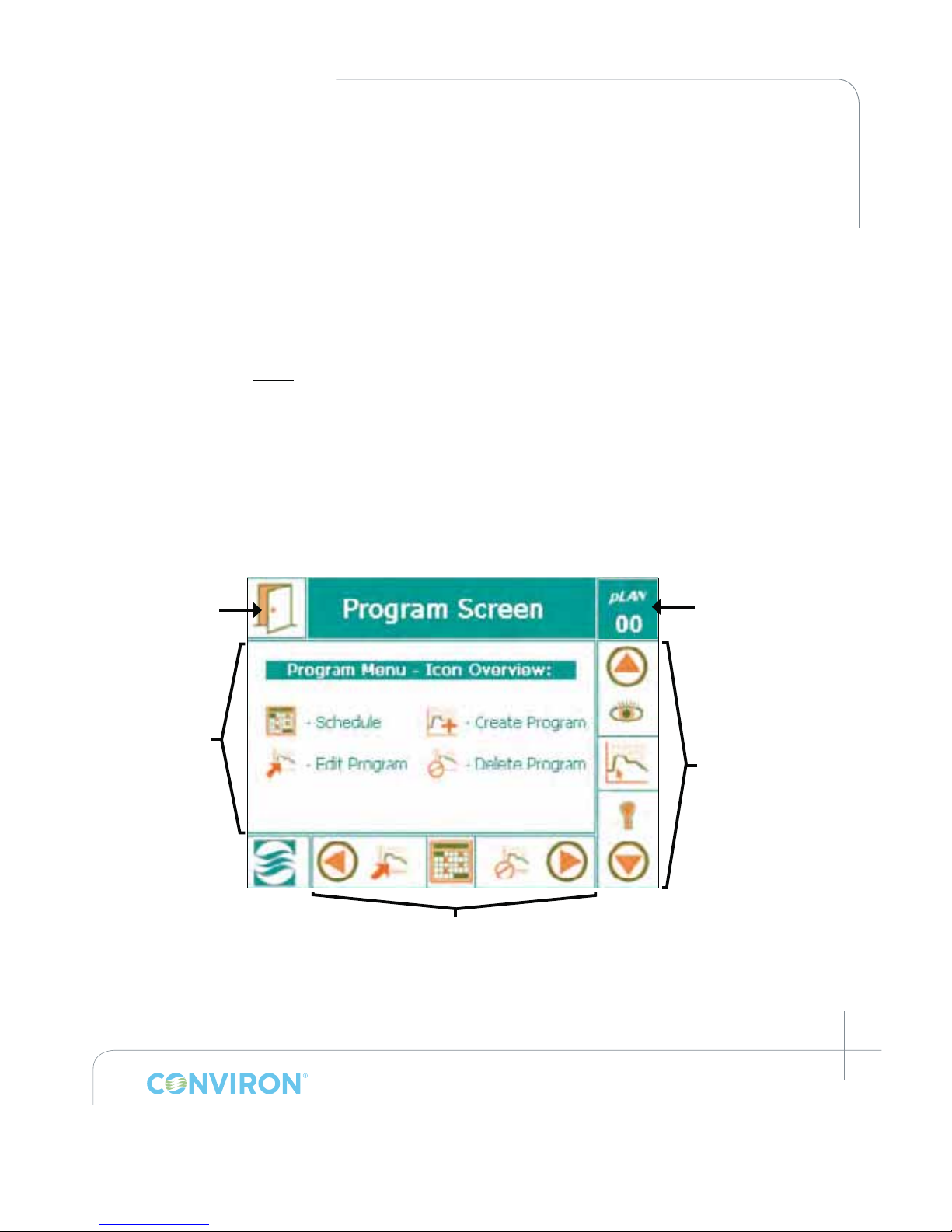
This chapter details the procedures for programming the CMP6050 using the Program Screen
(Figure 5-1). Upon completion of this chapter, the User will be ready to start the chamber and
run a schedule. The settings entered in the Program Screen control the conditions in the plant
growth chamber.
A Program is dened as User specied experimental set-point data (in real time) that establishes
the desired operating conditions of the chamber. Each Program denes a single 24-hour period
and each Program starts at midnight. A time of 00:00 therefore denotes a midnight setting. The
CMP6050 controller can store up to a maximum of 16 Programs while each Program can have
up to 48 timelines. Regardless of the number of timelines, the total period encompassed by all
timelines within a single Program is 24 hours.
Furthermore, the controller does not run individual Programs – it runs a Schedule. A Schedule
is dened as a User specied sequence of Programs linked together to form a Schedule. A
Schedule can have up to a maximum of 8 Programs where each Program can be repeated from
1 to 99 times, or set to innity.
5.1 Program Screen Icons and Locations
Chamber Selection
Exit Icon
Program Screen
Main Menu
Main Menu Bar
Bottom Menu Bar
Figure 5-1: Program Screen – Key Area Layout
Page 33
March 2015 | 253652R06
5-2
CHAPTER 5 | PROGRAM SCREEN
5.2 Program Screen Main Menu
The Program Screen-Main Menu contains four Sub-menus including
• Schedule
• Create Program
• Edit Program
• Delete Program
These sub-menus can be accessed in two ways – either directly on the main screen area or
via the Bottom Menu Bar. Both methods contain the same information and options. User
preference will determine the access method. If using the main screen area, simply tap the
desired sub-menu. If using the Bottom Menu Bar, use the right and left navigation arrows until
the desired sub-menu is displayed in the centre eld and then tap that sub-menu icon.
5.3 Accessing the Program Screen
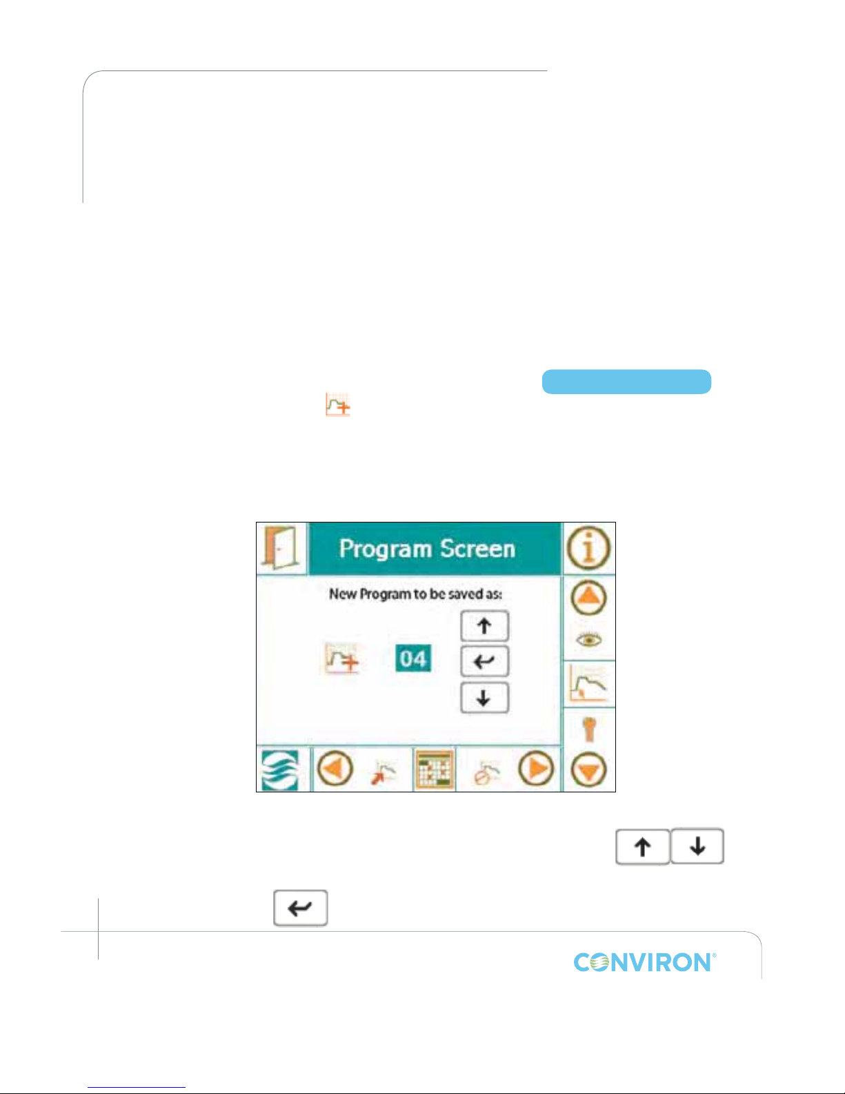
Tap the Create Program icon to access the Create Program sub-menu screen. (Figure 5-2:
Program Screen: Save New Program As...)
• By default, the rst program number will show as 01. If a program already exists, then
the CMP6050 will automatically show the next program number available.
• If another program number is required, use the UP or DOWN
buttons to select the program. (Programs do not have to be saved
in numerical sequence.)
• Tap the ENTER button once a program number has been selected.
Access Level 1
Figure 5-2: Program Screen: Save New Program As...
Page 34
March 2015 | 253652R06
5-3
CHAPTER 5 | CMP6050 Operator’s Manual
5.3.1 Create Program
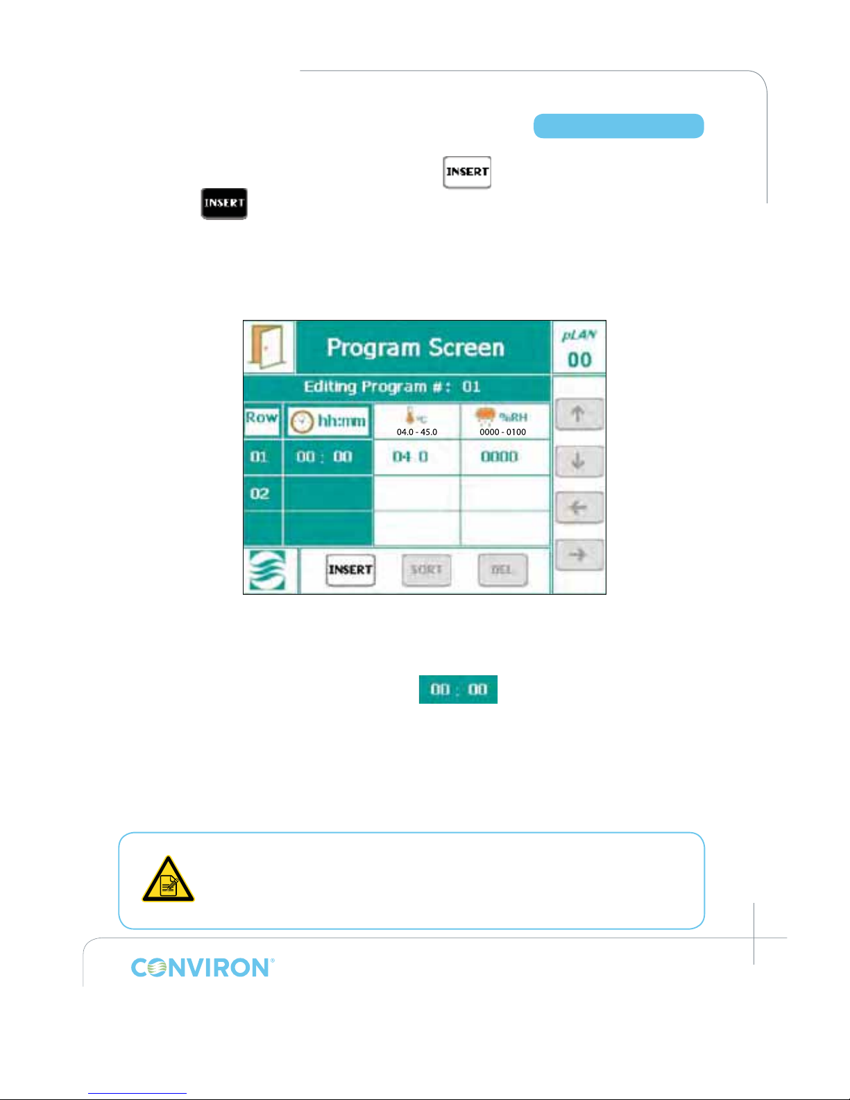
1. To activate the rst timeline (Row) number, tap the button. The INSERT button will
turn black
once tapped and will return to its original state once you have selected the
timeline row number
2. Tap the timeline row number 01 in the program to create the rst timeline (Figure 5-3: Creating
a Timeline).
• All the default values will appear in the rst timeline.
• All the program timeline icons will now be activated.
(i.e. INSERT, SORT, DEL, and all arrow buttons)
3. To change time, tap the hours and/or minutes
eld in the rst timeline (Row 01).
• Hours and minutes must be entered separately.
• Touch the 00: eld for hours.
• Touch the :00 eld for minutes.
• A standard pop-up keypad will appear allowing for numerical data entry. (Figure 5-4:
Numeric Keypad)
When entering the time field, you are NOT entering a time duration in hours
and minutes but rather the actual clock-time at which point you would like the
chamber to change to the new set-point parameters. This is why setting the
actual Time and Date in Section 3.2 was important. Also, remember that the
time field format is 24-hour.
Access Level 1
Figure 5-3: Creating a Timeline
Page 35
March 2015 | 253652R06
5-4
CHAPTER 5 | PROGRAM SCREEN
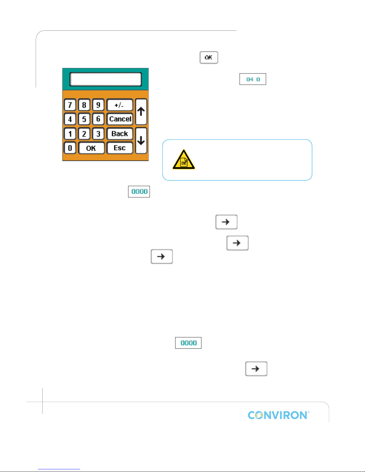
4. Tap the OK button once data has
been entered.
5. Tap the temperature value
to set the
desired Temperature.
• Temperature value is the only parameter with a
decimal point. Therefore, always enter 3 digits and
a negative sign if the chamber is low temp. Note:
set-point parameters have specied ranges. The
controller will only allow values to be entered that
are within the range.
Temperature is the only Set-point
parameter that is provided on every
controller. All other parameters are
optional based on the configuration/
application of the chamber.
6. Tap the humidity value to set the desired Humidity percentage. (If available).
• The program screen can only display two set-point columns in a single display
frame. To access additional parameters press
• If more than two parameters are controllable, the
will be displayed
white. Otherwise, the
will be displayed grey, indicating no other
parameters are available.
7. There are many different lighting congurations for the CMP6050 and it is beyond the scope
of this Manual to dene every one. Generally speaking, every controller is congured by
Conviron for each application. When creating a Program, and provided that Lighting is
an available controlled parameter with your chamber conguration, the lighting set-point
is accomplished in the same manner as other set-points. Tap the Light eld and use the
keypad screen to select the desired set-point. If there are multiple Lighting columns for your
conguration, then repeat this procedure for each column.
8. If equipped with CO
2
, tap the CO2 value and/or the Auxiliary value to set the
desired levels.
• To view/modify the CO
2
/Auxiliary values, touch the right arrow button
to navigate to the eld box.
• To add more programs, repeat the above steps in order.
Figure 5-4: Numeric Keypad
Page 36
March 2015 | 253652R06
5-5
CHAPTER 5 | CMP6050 Operator’s Manual
9. To add another Timeline to the program, tap the eld and then the 02 Timeline Row.
Default values will be displayed. Repeat steps 3 – 8 above to complete the new Timeline.
Insert additional Timelines as required.
A maximum of 48 Timelines (Rows) can be entered for each Program. Each
Program covers a 24-hour Period.
If Timelines are not in chronological order, press the Sort button at the bottom of the screen
to automatically sort the rows of the program by time.
10. Program Editor Entry Removal
The program editor now allows entry of a "---" for each process at a given timeline. The "---"
entry tells the process to remain unchanged by the timeline. When a user enters a timeline into
a program, the value for each column will be initially set to the default value for the
corresponding process. The user can then touch the set point eld to change the value of one
process without affecting other environmental conditions within the chamber:
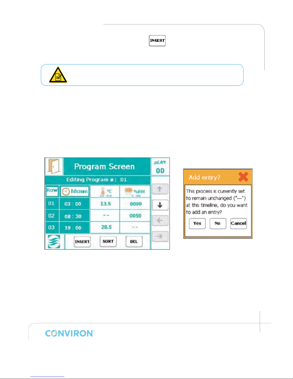
Touching a valid entry will bring up a key pad containing a “- - -“ button as in Figure 5-4. This
button will disable the entry for that process at that particular timeline.
Touching a eld that contains a non-entry or “- - -“ will bring up a dialog box asking to
conrm adding an entry (Figure 5-6: Add Entry dialog box).
Figure 5-5: Program Editor Screen
Figure 5-6: Add Entry
dialog box
Page 37
March 2015 | 253652R06
5-6
CHAPTER 5 | PROGRAM SCREEN
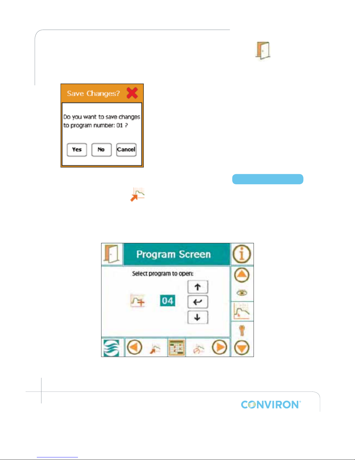
11. Once all the Timelines have been entered into the program, tap the EXIT button at
the top, left hand side of the display screen.
• A pop-up window will appear to conrm saving the
program. (Figure 5-7)
• Tap the YES button to save and return to the
Program Screen.
• Tap the NO button to cancel all entries made to the
specic program and return to the Program Screen.
• Tap the CANCEL button to go back into the
program editor and modify any required changes to
the Timelines.
5.3.2 Edit Program
Tap the edit program icon to access the following screen (Figure 5-8: Program Screen:
Select the program to edit). The default value is program 01. If more than one program has
been stored, the User may select the program to open. Use the scroll and enter tabs to open
the select Program.
• Editing a program has the same procedure as creating a program.
• Touch the necessary eld box to modify the Timeline values.
Figure 5-7: Pop-up window to
conrm saving the program
Access Level 1
Figure 5-8: Program Screen: Select the program to edit
Page 38
March 2015 | 253652R06
5-7
CHAPTER 5 | CMP6050 Operator’s Manual
1. To delete a Timeline in the program, tap the DEL button
• The DEL button will turn black
2. Now tap the desired Timeline row number to be deleted.
Note that the tab turns back to its original state.
3. To add additional Timelines to the program, repeat step 9 from the previous section.
4. Once all modications have been entered, tap the EXIT icon on the top, left hand side of
the display screen. A pop-up window will appear to conrm saving the edited program.
A program can be edited while the unit is in operation ( CMP6050 Software
Version 2.10 or greater).
5.3.3 Delete Program
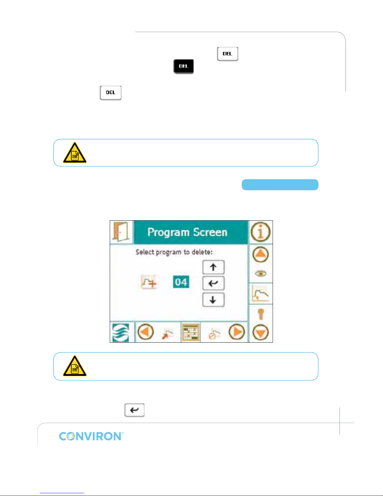
Tap the Delete Program icon to access the following screen (Figure 5-9: Program Screen: Select a
program to delete).
A program cannot be deleted while the unit is in operation.
1. To delete a program, tap the UP or DOWN buttons to select the desired program to delete.
2. Tap the ENTER button.
Access Level 1
Figure 5-9: Program Screen: Select a program to delete
Page 39
March 2015 | 253652R06
5-8
CHAPTER 5 | PROGRAM SCREEN
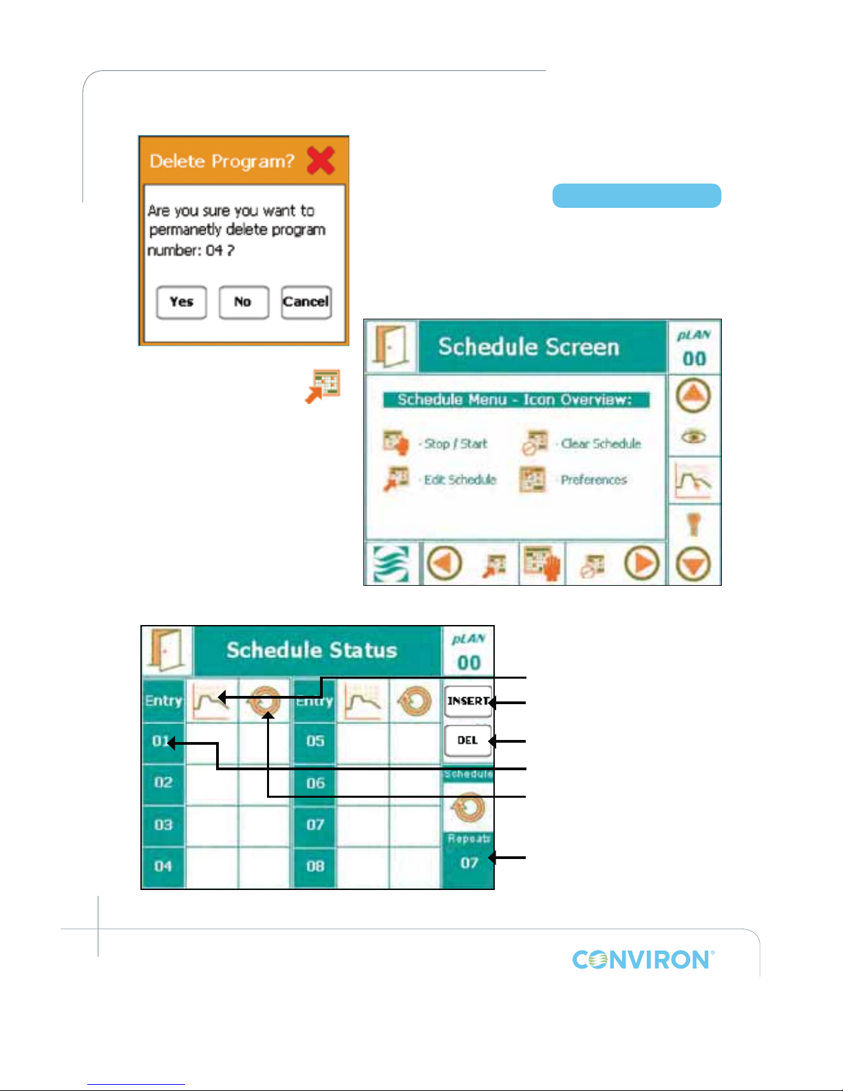
• A pop-up window will appear to conrm program
deletion (Figure 5-10: Conrmation message).
5.4 Schedule Screen
The CMP6050 scheduling system allows the User to enter
a sequence of Programs used to run chamber experiments
(Figure 5-11: Schedule Screen). When the schedule has run
through in its entirety, the chamber stops automatically.
5.4.1 Edit Schedule
Tap the Edit Schedule icon
to create or edit a schedule on the
schedule editor screen. Refer to
Figure 5-12 for an overview of the
schedule editor screen.
Figure 5-10: Conrmation message
Access Level 1
Figure 5-11: Schedule Screen
Figure 5-12: Schedule Editor Screen Overview.
14
02
03
01
16
04
01
02
01
01
01
01
01
05
0202
Program No.
Schedule Entry No.
No. of repetitions
Insert Entry
Delete Entry
No. of Schedule
repeats
Page 40
March 2015 | 253652R06
5-9
CHAPTER 5 | CMP6050 Operator’s Manual
Programs can be modied/edited while the chamber is running. However,
you cannot create or edit a Schedule while a Schedule is running. As such,
when you tap Edit Schedule, a pop-up box will appear to notify the User that
a Schedule is running. If this occurs, exit to the Schedule Screen and tap the
Stop/Start tab to stop the chamber. Now you can edit the Schedule.
1. Tap the INSERT button.
2. Tap the rst Entry of the schedule, which is 01. The
lowest program number will appear with
8
(innite) repetitions.
3. Tap the Program Number eld to toggle between
available programs until the program to run is displayed.
4. Tap the Number of Repetitions eld and select the
desired number of repetitions for the program.
• Enter 1 to 99, or
• To enter
8
press “0”
5. Repeat steps 1-4 to enter additional programs into the Schedule.
• Once all programs have been entered, and prior to saving the new/edited Schedule,
select the number of Schedule repetitions by tapping the “repeats” box at the
bottom right corner.
6. To delete any entry, touch the DEL button followed by the desired entry row.
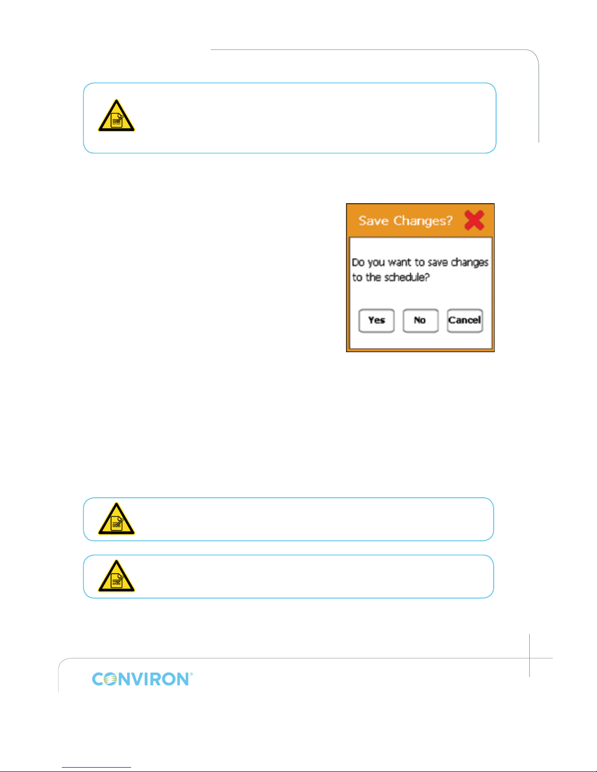
7. Once all programs have been entered into the schedule editor, touch the Exit button. A popup window will appear to conrm saving the schedule. (Figure 5-13)
For the Schedule Status screen displayed in Figure: 5-12, the schedule will run
a variety of 6 programs over 13 days and will repeat this sequence 7 times for a
total duration of 91 days.
Schedules can be set to run in either RAMP or STEP mode. Refer to Section 5.4.4
Preferences. The default setting is for parameters to run in RAMP mode.
Figure 5-13: Conrmation to
save changes.
Page 41
March 2015 | 253652R06
5-10
CHAPTER 5 | PROGRAM SCREEN
5.4.2 Start/Stop
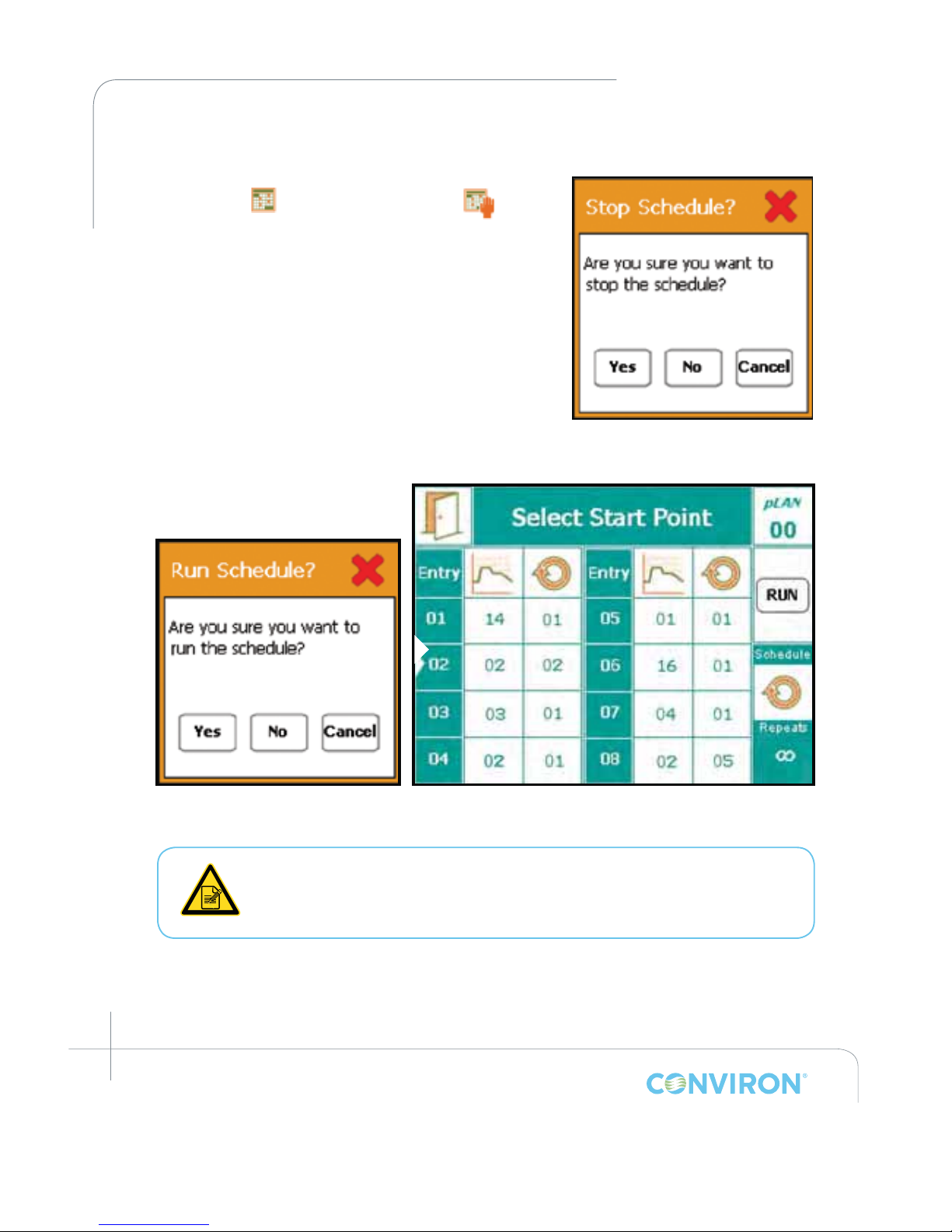
After setting up a schedule in the program screen, tap the
schedule icon
and then the start/stop icon to run
the chamber. A pop-up window appears to conrm stopping
(Figure 5-14) or running (Figure 5-15) the chamber depending
on whether a schedule is already running or not.
If you are starting to run a new schedule, then a new screen
entitled Select Start Point will appear (Figure 5-16). Review
the Schedule for correctness and then select the Schedule
entry number at which point you would like to begin the
Schedule. A small white arrowhead along the left side of the
Entry Number Column indicates the start point. Tap the Run
tab to start the Schedule.
If a chamber is shut down while running a schedule (power outage only)
upon starting up the chamber will resume running the schedule at the point
where it left off and continues at the actual chronological time. Once in
operation, to quickly stop a schedule, press the ON - OFF button.
Figure 5-14: Conrmation to
stop schedule.
Figure 5-15: Conrmation to
run schedule.
Figure 5-16: Select Start Point screen
Page 42
March 2015 | 253652R06
5-11
CHAPTER 5 | CMP6050 Operator’s Manual
5.4.3 Clear Schedule
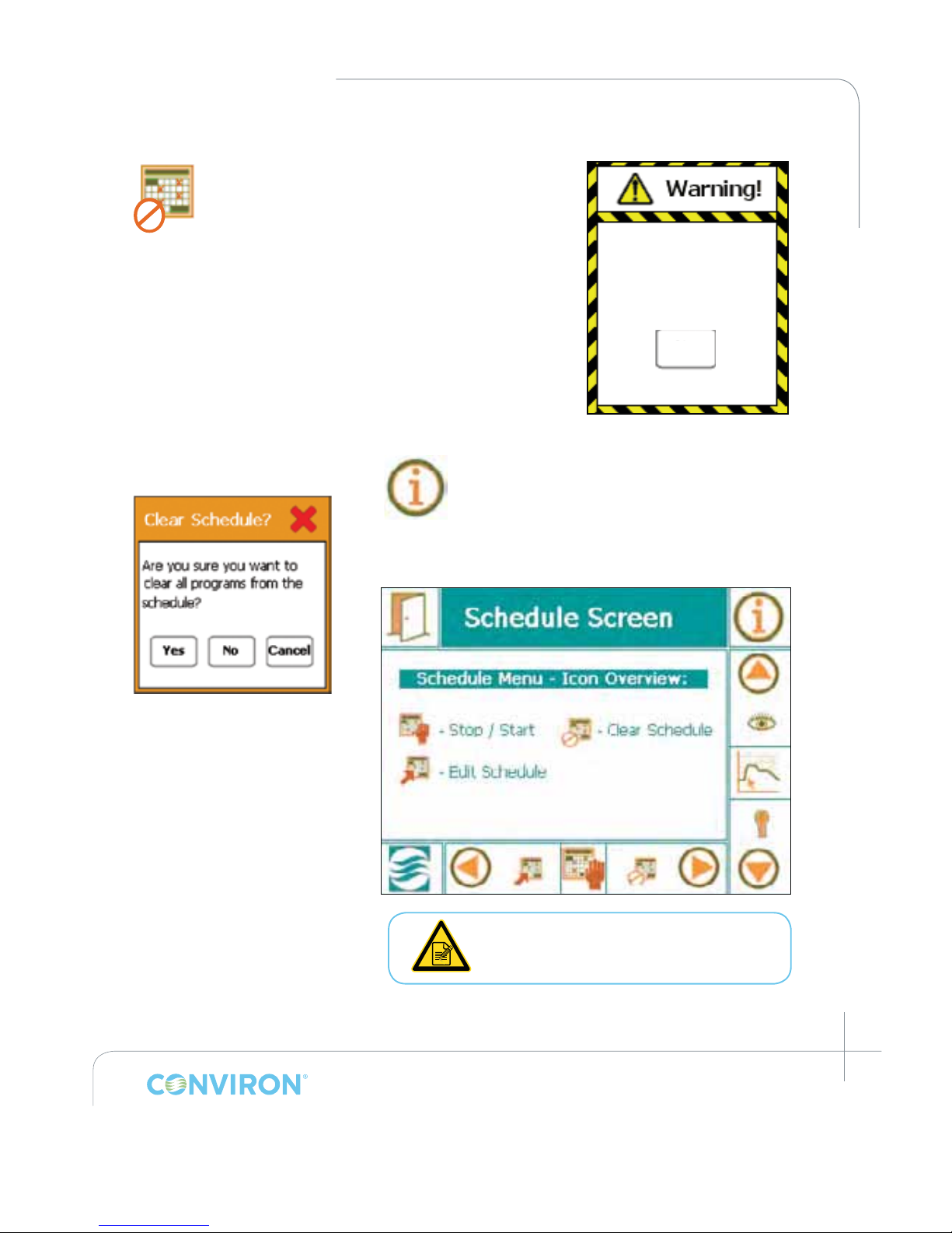
To clear the Schedule the chamber must rst be
stopped (refer to Section 5.4.2: Start/Stop). If you
attempt to clear the Schedule while a Schedule is
running, a pop-up Warning window appears as in
Figure 5-17.
Once the Schedule has been stopped, tap this icon to clear all
the programs within the schedule. The following pop-up
window displays. (Figure 5-18)
The display now returns to the Schedule Screen view (Figure
5-19). A new schedule can now be created per Section 5.4.1:
Edit Schedule.
• To see the schedule status while a
schedule is running, touch the
information icon from the Schedule
Screen (Figure 5-19).
Once a schedule has run through
completely, the unit will automatically
shut off.
Schedule cannot
be cleared while
running!
OK
Figure 5-17: Warning Window
Figure 5-18: Conrmation to
clear schedule.
Figure 5-19: Schedule Screen
Page 43
March 2015 | 253652R06
5-12
CHAPTER 5 | PROGRAM SCREEN
5.4.4 Preferences
5.4.4.1 Setting the Process Transition Mode – RAMP vs. STEP
1. Tap the Program icon . to access the Program Screen.
2. Tap the Schedule icon to activate the Schedule Screen.
3. Tap the Preferences icon
to activate the Schedule Preferences screen and
manipulate RAMP and STEP options.
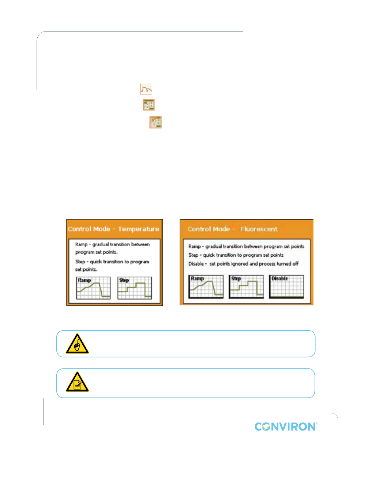
4. Select either RAMP or STEP as in Figure 5-20 or Figure 5-21. If in VAR process
control mode (see Section 2.12 for more information), there is an additional
transition mode available called Disable. The Disable feature allows the User to
disable active control for all processes individually (except temperature) without
deleting the process from a program. Note: The ability to RAMP non-temperature
processes may not be enabled on your software version.
5. Tap the Exit icon to save values and exit the setup.
When STEP Mode is selected, the tracking alarm feature (discussed in Section 6.4
Setting Alarms) is disabled.
For shock testing, use STEP mode. Do not modify Ramp mode values.
Figure 5-20: RAMP vs. STEP mode
for Temperature)
Figure 5-21: RAMP vs. STEP mode
for Fluorescent (only available in VAR mode)
Page 44
March 2015 | 253652R06
5-13
CHAPTER 5 | CMP6050 Operator’s Manual
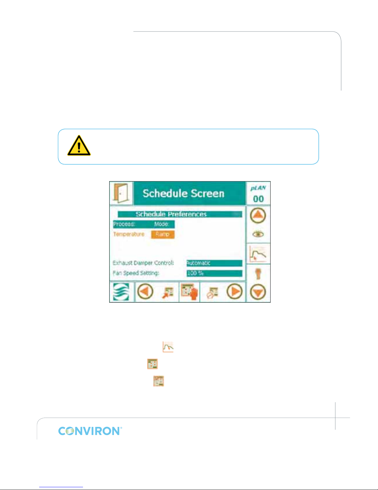
5.4.4.2 Fan Speed Control and Exhaust Damper Control
As an optional feature, clients can manipulate fan speed and CO2 exhaust by conguring the
Fan Speed Setting and the Exhaust Damper. Fan speed can be user adjusted between 0% and
100% within a factory preset minimum and maximum allowable fan rpm range. By default the
fan speed is set to 100%. The CO
2
Exhaust Damper Control has three modes, Automatic,
Open (override), and Closed (override). In Automatic mode, the position of the exhaust
damper is based on the CO
2
set-point. In Open (override) mode the damper remains open
while in Closed (override) mode the damper is closed.
When the fan speed is set to 0% it does not mean that the fan is no longer active.
A 0% setting by the User reduces the fan speed to the minimum allowable rpm
as per factory specications. Take precautions to ensure that the fan is off prior to
servicing to prevent injury.
To change the Fan Speed Setting and Exhaust Damper Control (see Figure 5-22):
1. Tap the Program Screen icon
. to access the Process Control Mode options.
2. Tap the schedule icon
to activate the eld.
3. Tap the Preferences icon
to activate the schedule screen and manipulate fan
speed settings.
Figure 5-22: Fan Speed and CO2 Exhaust Damper Setting
Page 45
March 2015 | 253652R06
5-14
CHAPTER 5 | PROGRAM SCREEN
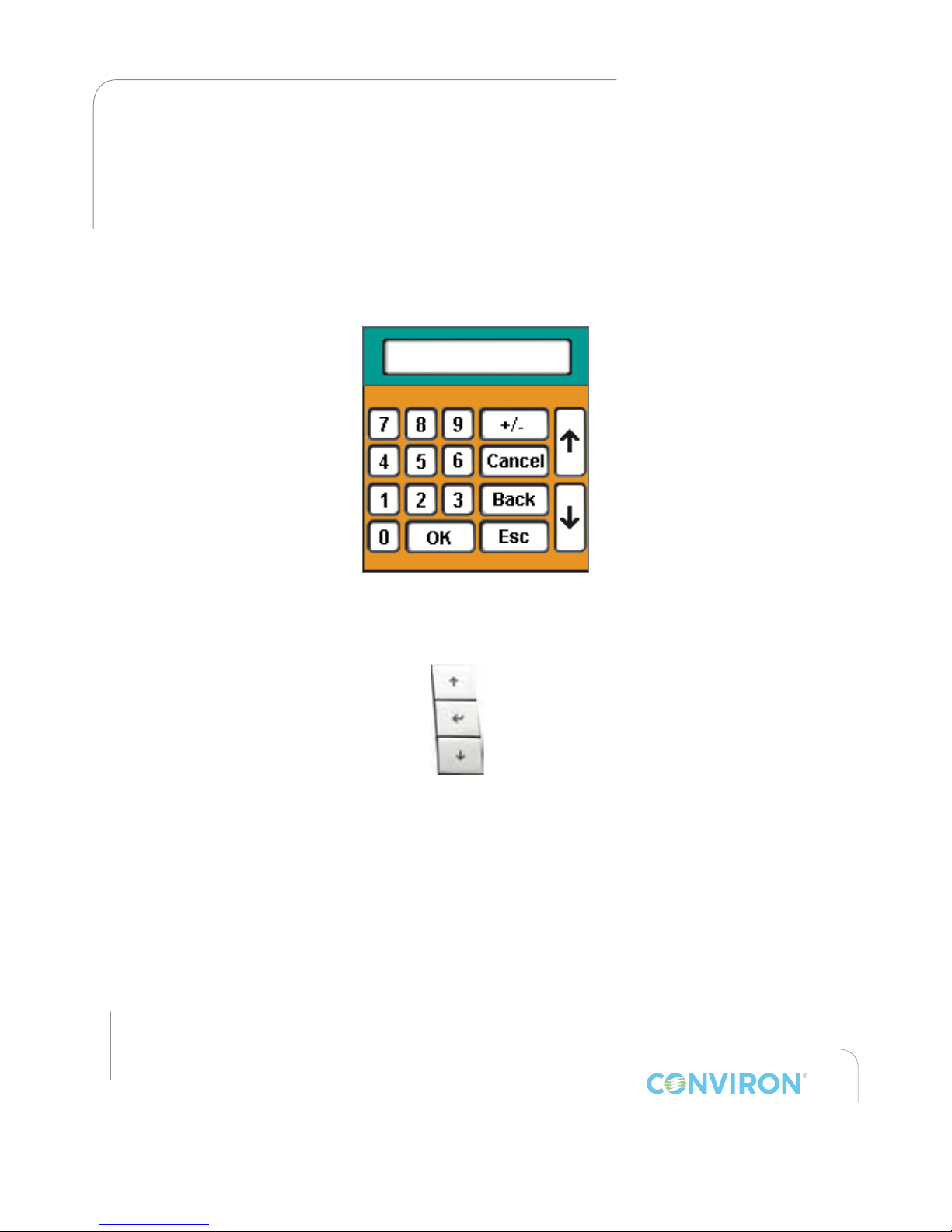
4. Tap the 100% next to Fan Speed Setting or the Automatic next to Exhaust Damper Control.
5. Enter a value of between 0% and 100% for the Fan Speed Setting using the keypad.
Tap the OK button once nished. An alternative to using the electronic keypad is to
use the Keys on the right side of the display (Figure 5-24). For the Exhaust Damper
Control, tap Automatic then use the controller keys to display Open (override) or
Closed (override) and Enter to set.
Figure 5-23: Keypad
Up
Enter
Down
Figure 5-24:
Controller Keys
Page 46
March 2015 | 253652R06
5-15
CHAPTER 5 | CMP6050 Operator’s Manual
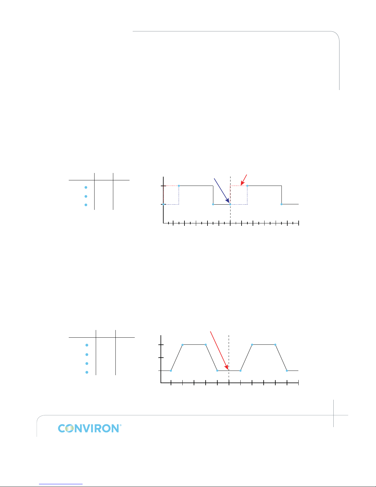
5.5 Understanding Program Transitions
Programs entered in the CMP6050 begin at 00:00 and end at 23:59. Conditions defined by
the last timeline of a program will run until 23:59, at which point the controller will load the
program file for the next day and look to the first timeline of that program to determine
process set points. Those set points are implemented at 00:00, regardless of the time
specified by the first timeline.
Figure 5-25 represents a transition from one day to the next for a program which turns the
chamber lights on at 6:00, and off at 18:00 (in STEP mode). Other set point conditions are
excluded for simplicity.
In order to maintain the same conditions in the chamber from 23:59 through 6:00 of the
following day, timeline 1 must be present at 00:00 with the same set point conditions as
were running until 23:59. In Figure 5-26 below, no timeline is necessary at 00:00 as the first
and last timelines of the program specify identical set point temperatures.
Figure 5-25: Midnight transition
requiring 00:00 timeline
Without timeline 1
00:00 16:008:0000:00 16:008:00 00:00
Time [hh:mm]
Lights ON
Lights OFF
Time Light
00:00 OFF
ON6:00
18:00 OFF
1
2
3
Timeline
1
1
Timeline 1 ensures the
lights in the chamber stay
off from 00:00 to 6:00
2
3
2
3
Figure 5-26: Midnight transition not
requiring 00:00 timeline
00:00 16:008:0000:00 16:008:00 00:00
Time [hh:mm]
20ºC
1
2
10ºC
15ºC
3
41
23
4
Time Temp
4:00 10ºC
20ºC8:00
16:00 20ºC
1
2
3
Timeline
4 20:00
10ºC
No timelines necessary at
23:59 or 00:00. Last and first
timelines of program specificy
identical set point conditions.
Page 47
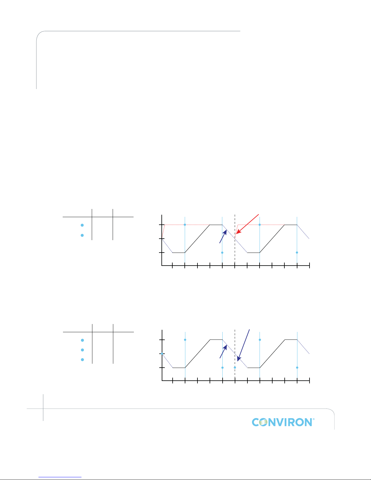
March 2015 | 253652R06
5-16
CHAPTER 5 | PROGRAM SCREEN
5.6 When Ramping Across Midnight is Necessary
The controller cannot automatically ramp across midnight. For this reason Conviron
recommends avoiding ramping across midnight if possible. However, if an experiment
requires the chamber to ramp one or more parameters across the transition at midnight, the
User must add necessary additional set points in order to ensure the desired ramp occurs
as intended. The amount of additional set points required will depend on whether or not
the process transition mode is gRAMP (control mode BASIC) or vRAMP (control mode
VAR). See Section 2.12 for more information on process control modes and corresponding
transition modes.
5.6.1 gRAMP
Figure 5-27 and Figure 5-28 demonstrate how to add a timeline to a program so that it is
possible to ramp temperature across midnight in gRAMP transition mode.
00:00 16:008:0000:00 16:008:00 00:00
Time [hh:mm]
20ºC
1
10ºC
15ºC
1
2
Time Temp
8:00 20ºC
10ºC20:00
1
2
Timeline
The controller can not look backward.
Therefore, with no timeline at 00:00 it will look
forward and instruct the chamber to set point
conditions specified by the first program
timeline (20ºC) at maximum ramp rate
Desired Ramp
2
Figure 5-27: gRAMP across midnight: INCORRECT
00:00 16:008:0000:00 16:008:00 00:00
Time [hh:mm]
20ºC
3
10ºC
15ºC
1
2
Time Temp
00:00 10ºC
20ºC8:00
1
2
Timeline
By adding a timeline at 00:00 with a set point
of 10ºC, the desired ramp continues as
intended at the global ramp rate.
Desired Ramp
2
3
1
3 20:00 10ºC
Figure 5-28: gRAMP across midnight: CORRECT
Page 48
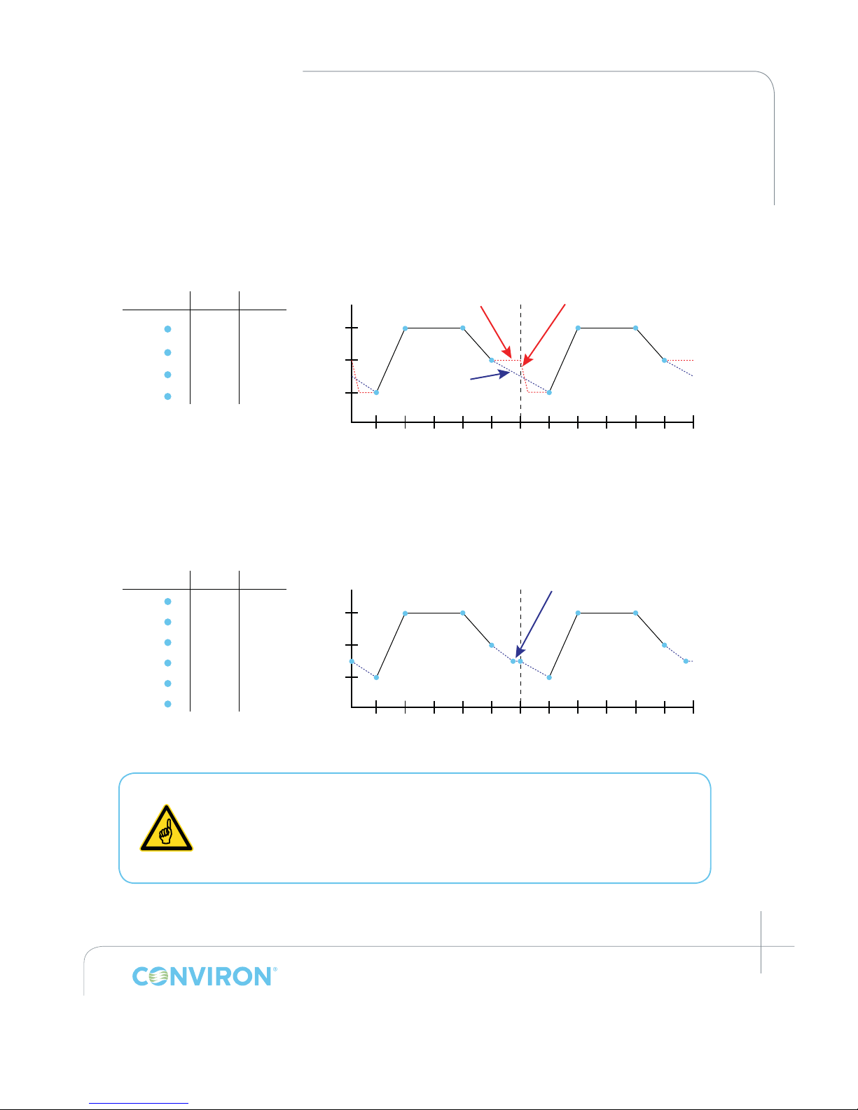
March 2015 | 253652R06
5-17
CHAPTER 5 | CMP6050 Operator’s Manual
5.6.2 vRAMP
Figure 5-29 and Figure 5-30 demonstrate how to add timelines to a program so that it is
possible to ramp processes across midnight when in vRAMP transition mode.
00:00 16:008:0000:00 16:008:00 00:00
Time
[
hh:mm
]
20ºC
1
2
10ºC
15ºC
3
4
1
23
4
Time Temp
4:00 10ºC
20ºC8:00
16:00 20ºC
1
2
3
Timeline
4 20:00
15ºC
At 00:00 the controller will instruct the
chamber to set point conditions
specified by the first program timeline
(10ºC) at maximum ramp speed
Desired Ramp
At 20:00 the controller will maintain
temperature specified by the last
timeline in the program (15ºC), as
there is no further set point from
which to calculate ramp rate
Figure 5-29: vRAMP across midnight: INCORRECT
00:00 16:008:0000:00 16:008:00 00:00
Time [hh:mm]
20ºC
2
3
10ºC
15ºC
4
6
2
34
Time Temp
00:00 12.5ºC
10ºC4:00
8:00 20ºC
1
2
3
Timeline
4 16:00 20ºC
With the addition of timelines 1
and 6, the ramp proceeds as
intended, spending only one
minute at steady temp
5
1
6
5
1
Timeline 6
exaggerated to
properly illustrate
transition.
5
6 23:59
20:00
12.5ºC
15ºC
Figure 5-30: vRAMP across midnight: CORRECT
To avoid unexpected conditions in the chamber, take care when planning
programs. Pay particular attention to program transitions. Ensure they
are well defined so that the controller interprets the settings as intended.
When possible, designate the first timeline of a program as 00:00 and the
last timeline as 23:59. Ensure the first and last timelines of programs use the
same set point conditions to avoid unexpected behavior.
Page 49
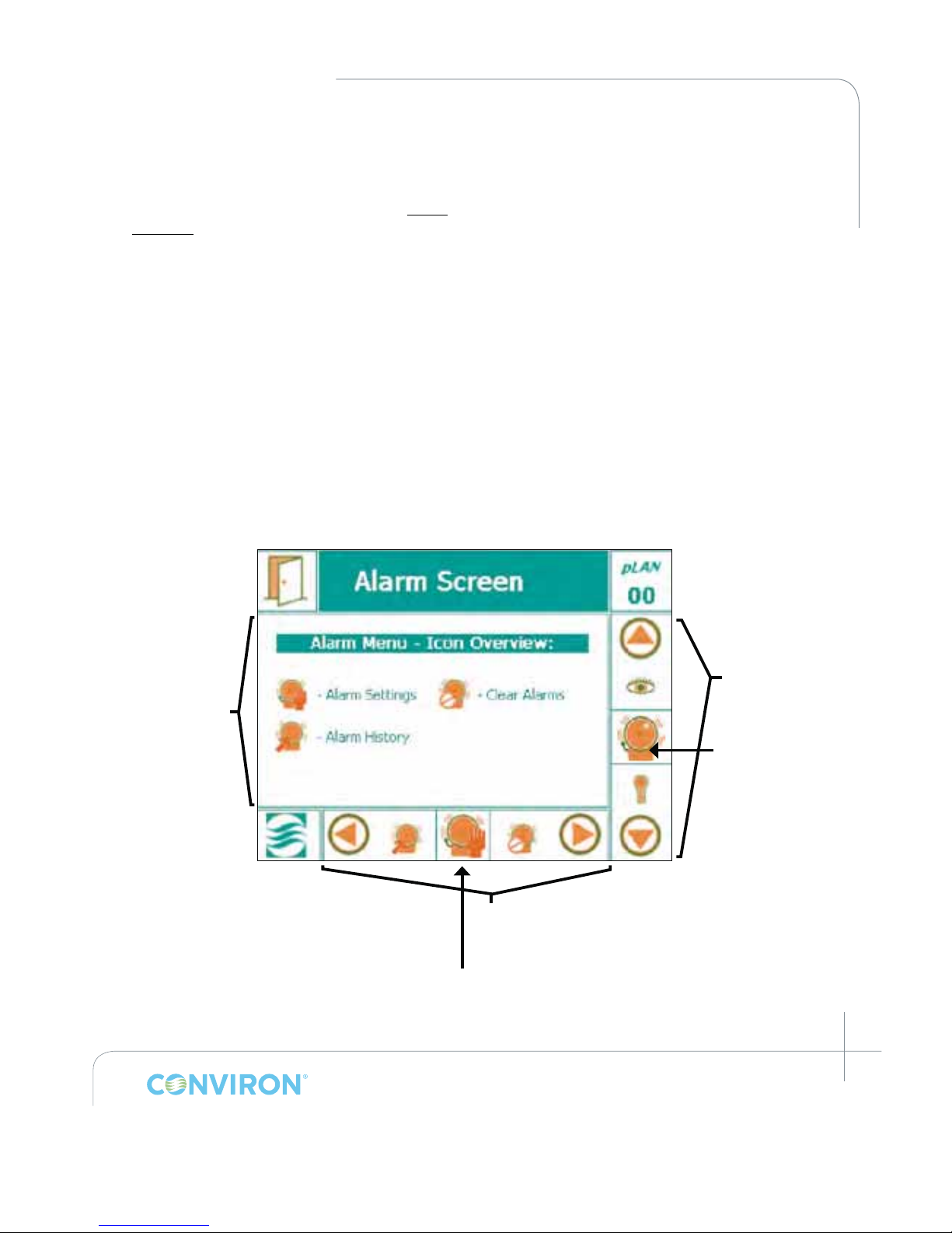
March 2015 | 253652R06
6-1
6.0 ALARM SCREEN
The alarm screen allows the User to set-up and manage alarm conditions for each chamber.
Alarms are used to notify the User when actual controlled parameters move outside of the
set-point conditions and their respective limits. With the ability to program alarms, receive
error messages and manage reporting, experimental research specimens can be effectively
protected. This section of the Manual provides information on setting-up and managing alarms
effectively. Topics covered include:
• Alarm Settings
• Alarm History
• Clear Alarms
6.1 Alarm Screen Icons
From the Main Menu Bar on the Main Status Screen, tap the Alarm Icon to access the Alarm
Screen. The Figure below illustrates the key areas of the Alarm Screen.
6.2 Alarm Overview
The CMP6050 contains a total of 20 alarm types. Based on the conguration of the unit, these
alarms will be either enabled or disabled by Conviron at the time of manufacture.
Figure 6-1: Alarm Screen – Overview
Main Menu Bar
Active Icon
Bottom Menu Bar
Alarm Screen
Main Menu
Alarm Icon
Page 50
March 2015 | 253652R06
6-2
CHAPTER 6 | ALARM SCREEN
Each of the alarms in the CMP6050 are identied by two main alarm classications – Warnings
and Shutdowns.
1. Warning
Notication of a non-critical alarm condition. The chamber will continue to operate under the
alarm condition(s). Examples of this type of alarm include humidity, light, open-door, etc.
2. Shutdowns
Notication of a critical alarm condition. The chamber will deactivate to prevent damage to the
chamber and/or experiment. Examples of this type of alarm include temperature, refrigeration
system malfunction, circulating fan malfunction, etc. Shutdown alarms are further classied by
Latching and Non-Latching as follows:
a) Latching
The chamber does not recover and user intervention is required. This alarm will stop the
schedule and force the user to manually re-start the chamber.
Example: High/low pressure.
b) Non-latching
The chamber automatically recovers without human intervention when the alarm
conditions are corrected and/or no longer active.
Example: temperature limits.
6.3 RAMP and STEP Mode
6.3.1 RAMP Mode Temperature Tracking Alarms
When temperature is set in RAMP mode (either gRAMP or vRAMP), an additional User-specied
alarm setting called Tracking is available. The Tracking alarm functions identically in both gRAMP
and vRAMP transition modes (see Section 2.12 Process Control Modes: BASIC and VAR, for more
information about gRAMP, vRAMP, and STEP transitions).
With Tracking, the User species a warning limit. This limit (e.g. ±2°C) is the tolerance around the
set point temperature that the User is willing to accept before the controller triggers a Warning
alarm. If the actual temperature exceeds the set point throughout the ramping phase by more
than the specied tolerance, a warning alarm is triggered. Tracking alarms are available for
temperature only.
In either gRAMP or vRAMP mode, the temperature parameter also has a shutdown limit.
This shutdown limit is similar to the Warning limit, however it represents a higher tolerance
(e.g. ±5°C) than the Warning limit. The Shutdown limit is the tolerance around the set point
temperature during ramping that the User is willing to accept before the controller triggers
a Shutdown Alarm. If at any time throughout the ramping phase the actual temperature
set in the shutdown limit differs from the set-point temperature by more that the specified
Page 51
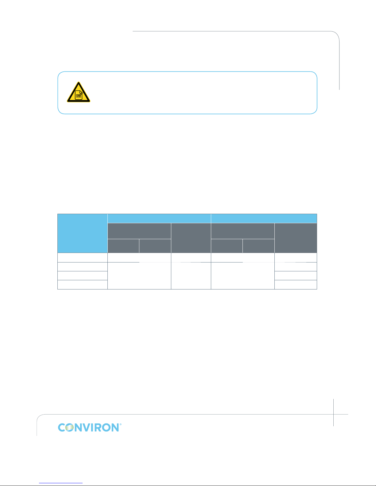
March 2015 | 253652R06
6-3
CHAPTER 6 | CMP6050 Operator’s Manual
tolerance, the chamber will be shut down and it will trigger a shutdown alarm. Automatic
shutdown is available only for the temperature parameter.
For the Warning limit in gRAMP or vRAMP mode, the actual conditions must
exceed the warning limit for 5 minutes before a warning alarm is triggered and
exceed shutdown limit for 5 minutes before a Shutdown (for temperature only)
is triggered. The reason for this is to prevent nuisance alarms where the warning
limit is exceeded for only a brief period.
6.3.2 STEP Mode - Limit Alarms
When the process transition mode is set to STEP, additional User-specied settings called “low”
and “high” limits are available for each parameter. When the low or high limits are exceeded, a
warning alarm is triggered. In the case of temperature, when the low or high limit is exceeded, the
chamber shuts down and a shutdown alarm is triggered.
6.3.3 RAMP and STEP Mode - Alarms and Shutdown
See Figure 6-2 for a summary of the warning alarms and user dened shutdown settings available
for gRAMP, vRAMP and STEP Mode for all processess:
Figure 6-2: RAMP and STEP Mode - Alarm and Shutdown
Parameter
RAMP Mode (gRAMP or vRAMP) STEP Mode
User Defined
Warning Alarm
User Defined
Shutdown
Alarm
Possible
User Defined
Warning Alarm
User Defined
Shutdown
Alarm
Possible
High Low High Low
Temperature
Yes
Yes*
No
Yes**
Humidity
n/a n/a Yes
No
Light No
CO
2
No
*gRAMP or vRAMP mode: During steady state or ramping phase to different temperature set points, the
tracking alarm feature is always enabled. That is, users can define the allowable tolerance that would trigger
an alarm. This tracking feature is applicable to temperature only. While in gRAMP or vRAMP mode for
temperature, the user can also define the shutdown tolerance that would trigger an automatic shutdown
(and a shutdown alarm).
**STEP mode: When in STEP mode the tracking alarm feature is always disabled. However, automatic
shutdown is still possible by setting the absolute temperature limits. temperature limits to trigger a
shutdown are user defined and should not exceed factory set limits. Any temperature exceeding the user
defined limits in STEP mode for the temperature parameter triggers a shutdown. Shutdown cannot be
triggered for other control parameters while in STEP Mode. However, exceeding defined limits will trigger
warning alarms for all other parameters.
Setting the process transition mode as either gRAMP, vRAMP, or STEP mode is described in further
detailin Section 5.4.4.1 Process Transition Mode – RAMP vs. STEP.
Page 52
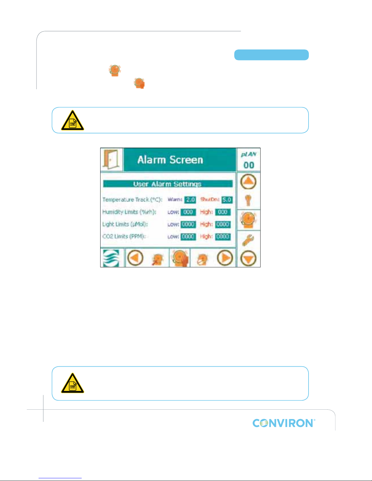
March 2015 | 253652R06
6-4
CHAPTER 6 | ALARM SCREEN
6.4 Setting Alarms
1. Tap the alarm icon to access the alarm screen.
2. Tap the Alarm Settings icon to access one of the following screens, depending on
whether the controller is set for RAMP (gRAMP or vRAMP) or STEP mode – Figure 6-3: Alarm
Screen in RAMP mode or Figure 6-4: Alarm Screen in STEP mode (default values shown).
At this point, the actual screen will vary depending on the unit chamber
conguration – that is, whether in RAMP (gRAMP or vRAMP) or STEP mode.
Figure 6-3: Alarm Screen in RAMP mode
6.4.1 When in RAMP Mode (gRAMP or vRAMP)
1. Set the Warning (low) tracking alarm tolerance.
Tap the Warn eld box to display a keypad and enter the low tracking alarm value.
• The value entered cannot be lower than the factory set minimum 2.0°C.
2. Set the Shutdown (high) tracking alarm tolerance.
Tap the shutdown eld box to display a keypad and enter the high tracking alarm value.
• The value entered must be in the range of 2.0° to 9.9°C
Setting the Low and High limits for the remaining parameters are independent of
RAMP or STEP Mode. Factory default values are set by Conviron and depend on
the chamber conguration. The User is able to change the default settings using
the same general instructions for setting the temperature limits.
Access Level 1
Page 53
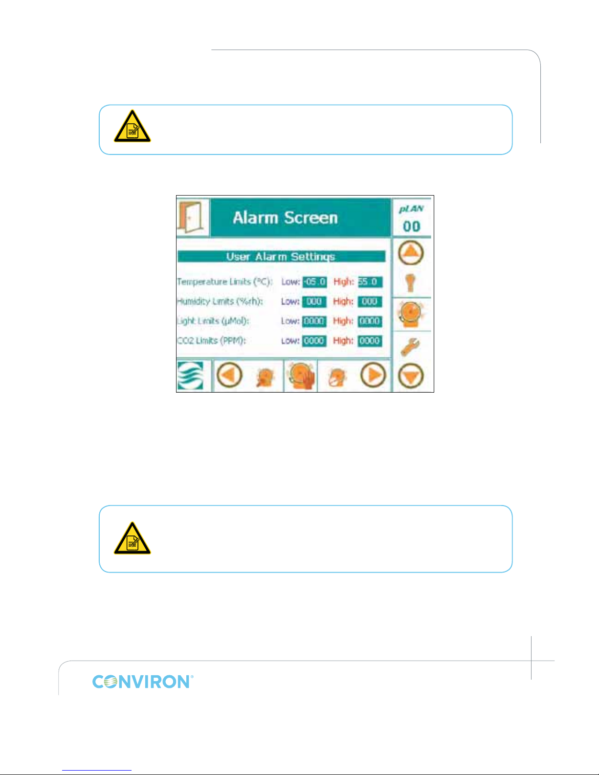
March 2015 | 253652R06
6-5
CHAPTER 6 | CMP6050 Operator’s Manual
6.4.2 When in STEP Mode
When in STEP Mode, Temperature Tracking alarms are disabled. Tracking
alarms are based on the set point at any particular time in the program,
including during ramping.
Figure 6-4: Alarm Screen in STEP mode (default values shown)
1. Set the low alarm limit.
Tap the low eld box to display a keypad and enter the low limit alarm.
2. Set the high alarm limit.
Tap the high eld box to display a keypad and enter the high limit alarm.
With Conviron CMP6050 software, the values entered in the limit elds are saved
and do not have to be re-entered when the system is re-booted. Always verify
when changing the temperature alarm limits that they are within the minimum
and maximum operating limits of the chamber. This will ensure that the ir33 does
not trigger shutdown before a high or a low temperature alarm.
Page 54
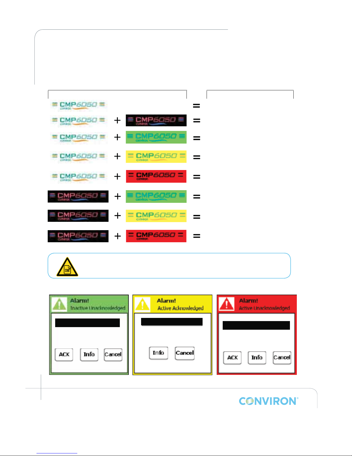
March 2015 | 253652R06
6-6
CHAPTER 6 | ALARM SCREEN
6.5 Alarm Status Indicators
The following Table provides a summary of alarm status indicators and their corresponding popup windows.
Chamber Shutdown Alert!
High temperature limit
Figure 6-5:
Chamber Warning Alert!
Temperature tracking
Figure 6-6:
High temperature limit
Chamber Shutdown Alert!
Figure 6-7:
No program running/
No alarms
Program running/No alarms
No program running/Inactive
Unacknowledged alarm (Figure 6-5)
No program running/Active
Acknowledged alarm (Figure 6-6)
No program running/Active
Unacknowledged alarm (Figure 6-7)
Program running/Inactive
Unacknowledged alarm (Figure 6-5)
Program running/Active
Acknowledged alarm (Figure 6-6)
Program running/Inactive
Unacknowledged alarm (Figure 6-7)
Status Indicator
Definition & Corresponding
Pop-up Window
Tapping the Status Indicator while any of the alarms states are active will provide
details of the alarm condition and additional options.
Page 55
March 2015 | 253652R06
6-7
CHAPTER 6 | CMP6050 Operator’s Manual
6.6 Alarm Corrective Action
For any of the above alarm conditions, tap the CMP6050 logo to access the corresponding pop-up
Alarm Screen.
1. Adjust the alarm settings if necessary.
2. Repair the fault where necessary.
3. Shut down and restart the chamber.
Inside the control panel is an independent temperature shut-off device called
the ir33. This ir33 acts as a secondary fail-safe protector that shuts off the
chamber if its temperature limits are exceeded. The ir33 is set by Conviron and
is factory protected.
The factory default setting for the ir33 temperature limit is 10˚C beyond the
chamber operating range. The standard operating range of a chamber is +4˚C to
+45˚C while the standard ir33 shutdown settings are -6˚C to +55˚C depending on
the chamber size, size of the compressor and other factors. Always ensure, when
changing the (Alarm) temperature limits, that the limits are still within the minimum
and maximum operating limits for the Chamber. This will ensure that the ir33 only
triggers in the event that the actual temperature exceeds the Chamber's minimum
or maximum temperature limit by 10˚C. It will also ensure that the ir33 does not
trigger before a high or low temperature tracking alarm.
The ir33 is located inside the control panel where there is live high voltage.
Contact Conviron Client Services for more information or help if necessary.
Page 56
March 2015 | 253652R06
6-8
CHAPTER 6 | ALARM SCREEN
6.7 Alarm Types
Following is a list of the 21 alarm types along with a description of each.
Warnings:
Bootup Alarm A message that is generated each time the
controller re-boots.
Temperature Tracking Warning Alarm A warning message when the temperature drifts
beyond the tolerance around the set-points.
Chamber Off Alarm Chamber power shuts off while a program is running
as a result of the main contactor open.
High Humidity Warning Alarm A warning message that the humidity has drifted
above the high alarm.
Low Humidity Warning Alarm A warning message that the humidity has drifted
below the low alarm.
High CO
2
Warning Alarm The amount of CO2 in the chamber is above
the alarm.
Low CO
2
Warning Alarm The amount of CO2 in the chamber is below the alarm.
High Light Warning Alarm The lighting intensity (in uMOL) is above the alarm.
Low Light Warning Alarm The lighting intensity (in uMOL) is below the alarm.
Lights are ON A warning message that lights are ON during
dark cycle.
Open Door Warning Alarm A warning message that the chamber unit door is open
for more than 60 seconds. The Chamber will shut down
after 5 minutes if the door remains open after that time.
(Available in just a few schedules)
High Pressure Warning Alarm A warning message that the refrigeration unit has
run above the high pressure limit value for more
than 30 seconds.
Low Pressure Warning Alarm A warning message that refrigeration unit has run
below the low pressure limit value for more than
30 seconds.
Loft Temperature Warning Alarm A warning message that the lamp loft temperature
has exceeded the set-point
Plenum Temperature Warning Alarm A warning message that the plenum temperature is
above or below the set-point.
Page 57
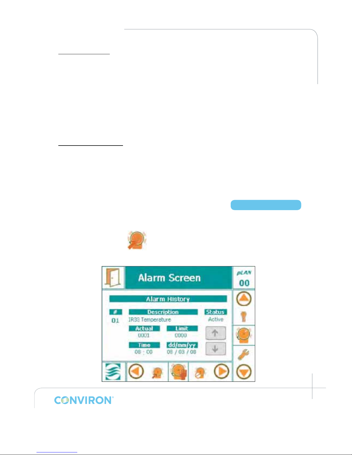
March 2015 | 253652R06
6-9
CHAPTER 6 | CMP6050 Operator’s Manual
Shutdown Latching:
High Pressure Count Alarm A warning message that the high pressure switch has been
tripped off 3 times within the last 30 minutes.
Low Pressure Count Alarm A warning message that the low pressure switch has been
tripped off 3 times within the last 30 minutes.
High Pressure Time Alarm A warning message that the high pressure switch has tripped
off for more than 30 seconds.
Low Pressure Time Alarm A warning message that the low pressure switch has
been tripped off for more than 30 seconds.
Shutdown Non-Latching:
ir33 Temperature
Shutdown Alarm
Chamber shut off as a result of exceeding the ir33
temperature settings.
Temperature Tracking
Shutdown Alarm
Chamber shut down as a result of the temperature
exceeding the user dened tracking tolerance, which is a
higher tolerance than the warning limit.
6.8 Alarm History
The Alarm History provides alarm information stored in the CMP6050 for the User to view. The
information provides a history of every alarm that the chamber encountered.
Tap the Alarm History icon to access the following screen. (See Figure 6-10)
Access Level 1
Figure 6-10: Alarm History Screen
Page 58
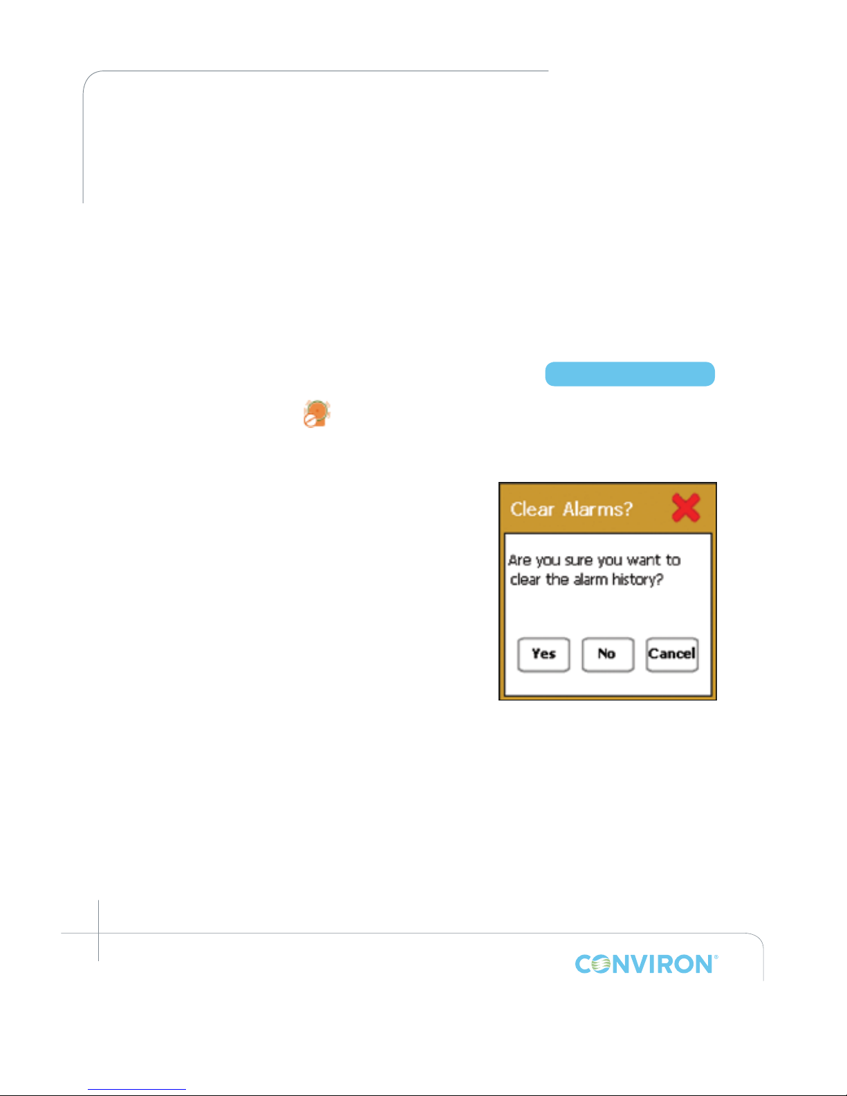
March 2015 | 253652R06
6-10
CHAPTER 6 | ALARM SCREEN
# Indicates the alarm in sequence of alarm events.
Description Indicates the alarm cause or malfunction.
Status Presents the Alarm Indicator (Ref. Section 6-5 Alarm Status Indicators)
Actual Actual value achieved of the parameter.
Limit Set-point limit of the parameter.
Time Indicates the time of the alarm set-off.
DD/MM/YY Indicates the date of the alarm set-off.
• Use the UP or DOWN arrow buttons to view the alarm history
6.9 Clear Alarms
Touch the Clear Alarms icon to access the following pop-up window:
Touch the Yes, No, or the Cancel button
to conrm (Figure 6-11).
Access Level 1
Figure 6-11: Conrmation to
clear alarm.
Page 59
March 2015 | 253652R06
7-1
7.0 SECURITY SCREEN
The CMP6050 has a security feature to manage Users by managing their level of access. The
feature requires Users to be set-up (a maximum of 3 User ID passwords can be assigned). Once
this is completed (and provided Security is turned On), Users are required to login – this is to
ensure that Program modications are made by authorized personnel only. The Administrator
can override all Users and can access all programming functionality.
The default for security features is to be turned Off (the CMP6050 is shipped with security
features turned Off). This enables any User to start the chamber and become familiar with the
chamber controls without having to enter a password.
It is recommend that a security Administrator be assigned to administer User
login authority and that security features be added as soon as possible.
7.1 Security Overview
With security enabled, there are three types of Users in the CMP6050 including:
• Users (Access Level 1)
• Administrators (Access Level 2)
• Factory (Access Level 3)
Users have Level 1 access which means they have access to the basic features such as
Programming, Alarms, Trend Graphs, and some of the Option features. Administrators have
Level 2 access which includes Level 1 access plus additional Service and Option features.
Factory has Level 3 access which includes Level 2 access plus other Service and conguration
features. Section 7-4: Edit User Screen provides details on setting up the Users and enabling the
Security feature. A step-by-step instruction is provided.
Access Level 1
When Security is turned OFF, anyone can access the Level 1 and 2 features.
For this reason, it is recommended to setup the Administrator and User login
authorities as soon as possible.
Page 60
March 2015 | 253652R06
7-2
CHAPTER 7 | SECURITY SCREEN
7.2 CMP6050 Level Access
The following table provides CMP6050 access levels available to the User, Administrator, or
Service/Factory personnel. Access level is password enabled. In this manual, access level codes
are presented at the beginning of every chapter to inform the user of specic access required.
Menu Sub-Menu Location (Page) Access Level
Status Options Input Offset 8-1 1
Time & Date 8-3 1
Security On/Off 8-4 2
Startup Delay 8-2 1
Setup 8-4 1
Security Login 7-5 1
Logout 7-6 1
Change Password 7-3 1, 2
Service I/O Status 10-2 1
CONVIRON Access n/a 3
User Reset n/a 2
O/P Runtimes n/a 2
PID Settings n/a 2
Alarms Settings 6-4 1
History 6-9 1
Clear Alarms 6-10 1
Trend Graph N/A 9-1 1
Program Create 5-3 1
Edit 5-6 1
Schedule 5-8 1
Delete 5-7 1
Legend
1 = User access 2 = Administrator access 3 = Factory access
Factory login is only available to Conviron personnel.
Page 61
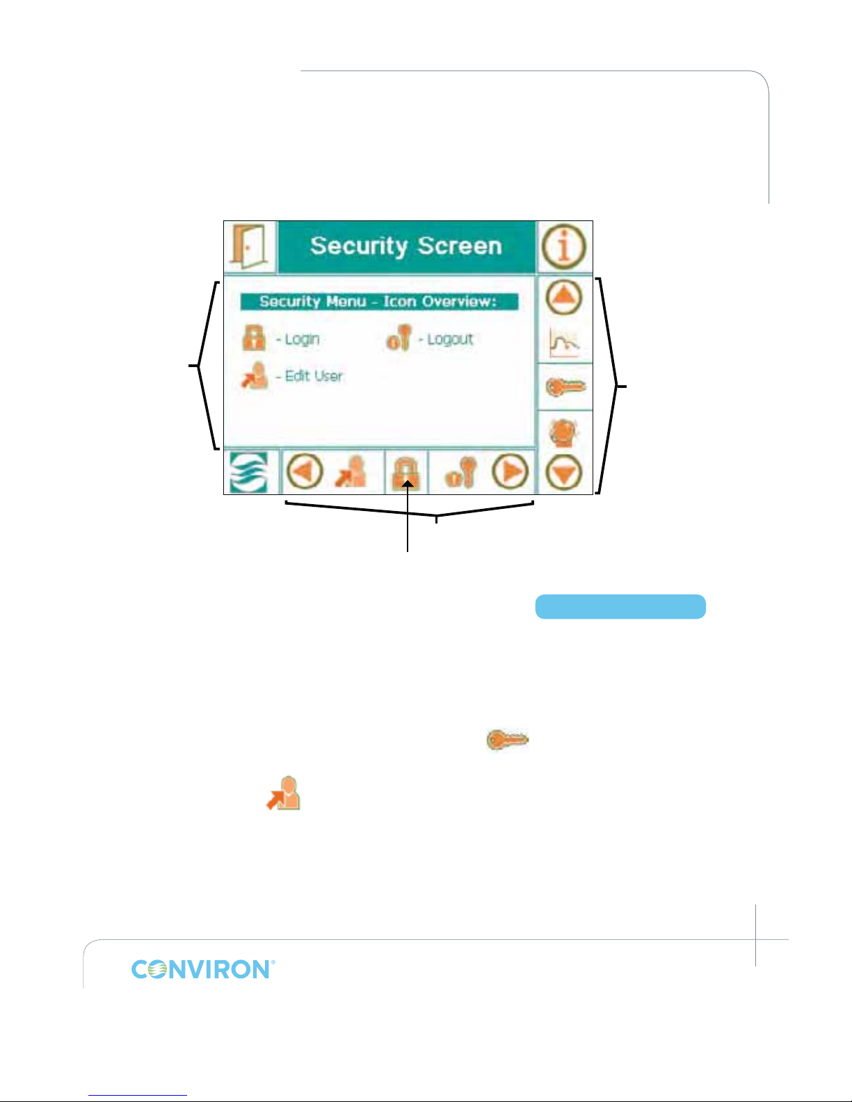
March 2015 | 253652R06
7-3
CHAPTER 7 | CMP6050 Operator’s Manual
7.3 Security Screen Icons and Locations
The gure below (Figure 7-1: Security Screen Layout) presents the key features and layout of the
Security Screen. This is the screen used to setup Administrator and User passwords.
7.4 Edit User Screen - Change Password
The rst step to setting up the Security feature is to setup the Administrator. The CMP6050
comes from the factory with a default Administrator password already set up. Note, this
password must be changed as soon as possible. The default password is 72343. Using this as
the current password, assign an Administrator and change the Administrator password. This is
accomplished as follows:
On the Main Menu Bar, scroll up or down until the Key icon appears as the active Icon.
Tap the Icon to launch the Security Screen (Figure 7-1: Security Screen Layout).
Tap the Edit User icon in the bottom menu bar to access the Edit User screen (Figure
7-2).
To navigate through this screen, use the three (3) Keys on the right side of the display (Figure 7-3).
Active icon
Main Menu Bar
Security Screen
Main Menu
Figure 7-1: Security Screen Layout
Access Level 1, 2
Page 62
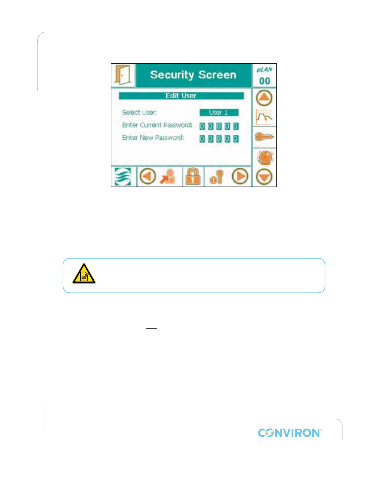
March 2015 | 253652R06
7-4
CHAPTER 7 | SECURITY SCREEN
Figure 7-2: Edit User screen.
1. Press the ENTER key to navigate to the Select User eld. A blinking white cursor will appear in
the eld box.
2. Press either the UP or DOWN Key to scroll through the available users. The options include
Users 1-3 plus Administrator.
3. Press the ENTER Key once you have selected the desired user.
It is recommended that the rst user to be setup be the Administrator. Once
the Administrator has been setup, other Users (up to 3) can be setup. An
Administrator can change their own (Level 2) password or a user (Level 1)
password, however, a user may only change their own (Level 1) password.
4. a) In the initial setup for the Administrator, insert the default password (72343) in the Enter
Current Password eld.
b) In the initial setup for each User, the Current Password is 00000. Press the ENTER Key ve (5)
times to skip through this eld.
5. In the Enter New Password section, a blinking white cursor is displayed in the 1st digit eld.
Use the UP/DOWN Keys to toggle the digit and press the ENTER Key to conrm.
6. Repeat Step 5 for every digit until completed. A notice will appear in the lower portion of the
screen: Password Change Successful.
7. Press the ENTER key again to return to the Security menu screen.
Page 63
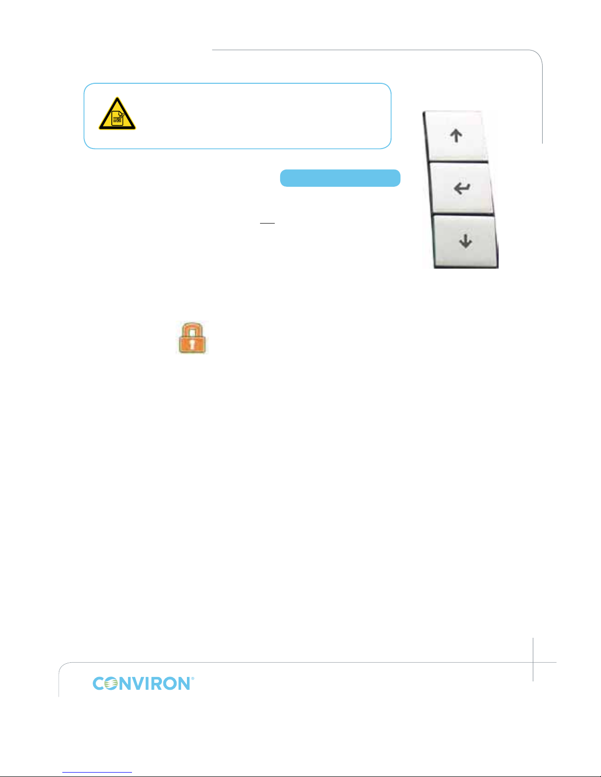
March 2015 | 253652R06
7-5
CHAPTER 7 | CMP6050 Operator’s Manual
The Administrator and all Users should record their
passwords for reference. If a User forgets/loses his/
her password, it can be reset by the Administrator.
If the Administrator forgets/loses his/her password,
Conviron Technical Services must be contacted.
7.5 Login Security Screen
Now that passwords have all been set up, Security should be turned ON.
If passwords are all set up and Security is not turned ON, anyone can
access Level 1 and 2 functions. When Security is turned ON, Users can
only access Level 1 functions while Administrators can access Level 1 and
2 functions.
Turning Security ON is accomplished from the Option Screen. Note
however that the Option Screen has not yet been covered at this point in the Manual. Please
refer to Section 8.6: Security On/Off for instructions on how to turn the Security ON. Once
Security has been turned ON, proceed with the following instructions regarding logging in.
Touch the Login icon to access the following screen. (Figure 7-4: Login screen)
To navigate through this screen, use the three (3) Keys on the right side of the display
(Figure 7-3).
1. Press the ENTER key to navigate to the Select User eld. A blinking white cursor will appear in
the eld.
• Factory is inaccessible to the User. It requires Access Level: 3.
2. Press either the UP or DOWN keys to scroll through the available users.
3. Press the ENTER key after selecting the desired user.
4. There should now be a blinking white cursor in the Enter Password (1st digit) eld box. Press
the UP or DOWN key to enter the code.
5. Once the last digit of the password has been entered, press the ENTER key. An unlocked
padlock icon and the text Login Successful are displayed when nished at the bottom of the
login screen.
• Authorized access to various Level-dependent sections of the CMP6050 is
now enabled.
• If a mistake is made entering a password, tap the Exit Icon. This will move you
back to the previous screen. You'll then have to re-enter the Login Screen.
Access Level 1
Figure 7-3: Display –
Right Side Keys
Page 64
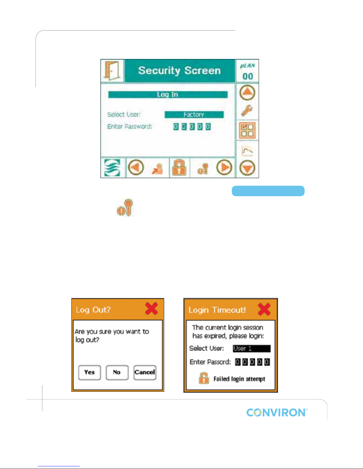
March 2015 | 253652R06
7-6
CHAPTER 7 | SECURITY SCREEN
7.6 Logout Security Screen
Touch the Logout icon to access the following pop-up window. (Figure 7-5)
Touch the Yes, No, or the Cancel button.
After selecting the desired button, by default, it will return to the Main Status Screen.
• After ve (5) minutes of inactivity, the CMP6050 will automatically Logout all Users, including
the Administrator. (Figure 7-6)
• A pop-up window will appear and inform the User to Log in again.
• Follow the same procedure as in Section 7.5 Login Security Screen to re-gain access.
Access Level 1
Figure 7-4: Login screen
Figure 7-5: Log out conrmation.
Figure 7-6: Login timeout.
Page 65
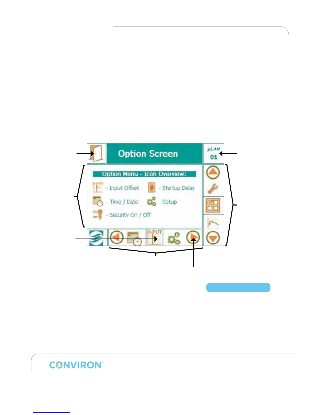
March 2015 | 253652R06
8-1
8.0 OPTION SCREEN
In previous sections of this Manual, instructions were provided to enable the User to startup and begin using the CMP6050 to control the Chamber. Those instructions comprised
the basics of what was required to begin operating the control system. In this section, an
expanded palette of features and options are presented. These new features provide the
User enhanced control over system operation. Some of the options and features presented
in this section affect the logged data, and as such it is important that the additional variables
be appropriately set.
8.1 Option Screen - Layout
The Option Screen presents five key menu options as illustrated below.
8.2 Input Offset (Sensor Calibration)
Input offset refers to sensor calibration which is a feature that allows the User to apply an
offset correction to the actual sensor reading. This is particularly useful when the User has an
independent sensor device that is considered to be highly accurate and that produces a slightly
different reading than the CMP6050 reading.
For example, if the chamber is running at 25°C and an independent temperature sensor is
placed into the chamber and it reads 24.3°C, provided the independent sensor is deemed to be
more accurate, a 0.7°C offset correction can be applied to the chamber sensor.
Figure 8-1: Option Screen Layout
Chamber Number
Exit Icon
Active icon
Menu Screen
Main Menu Bar
Bottom Menu Bar
NavigationArrow
Access Level 1
Page 66
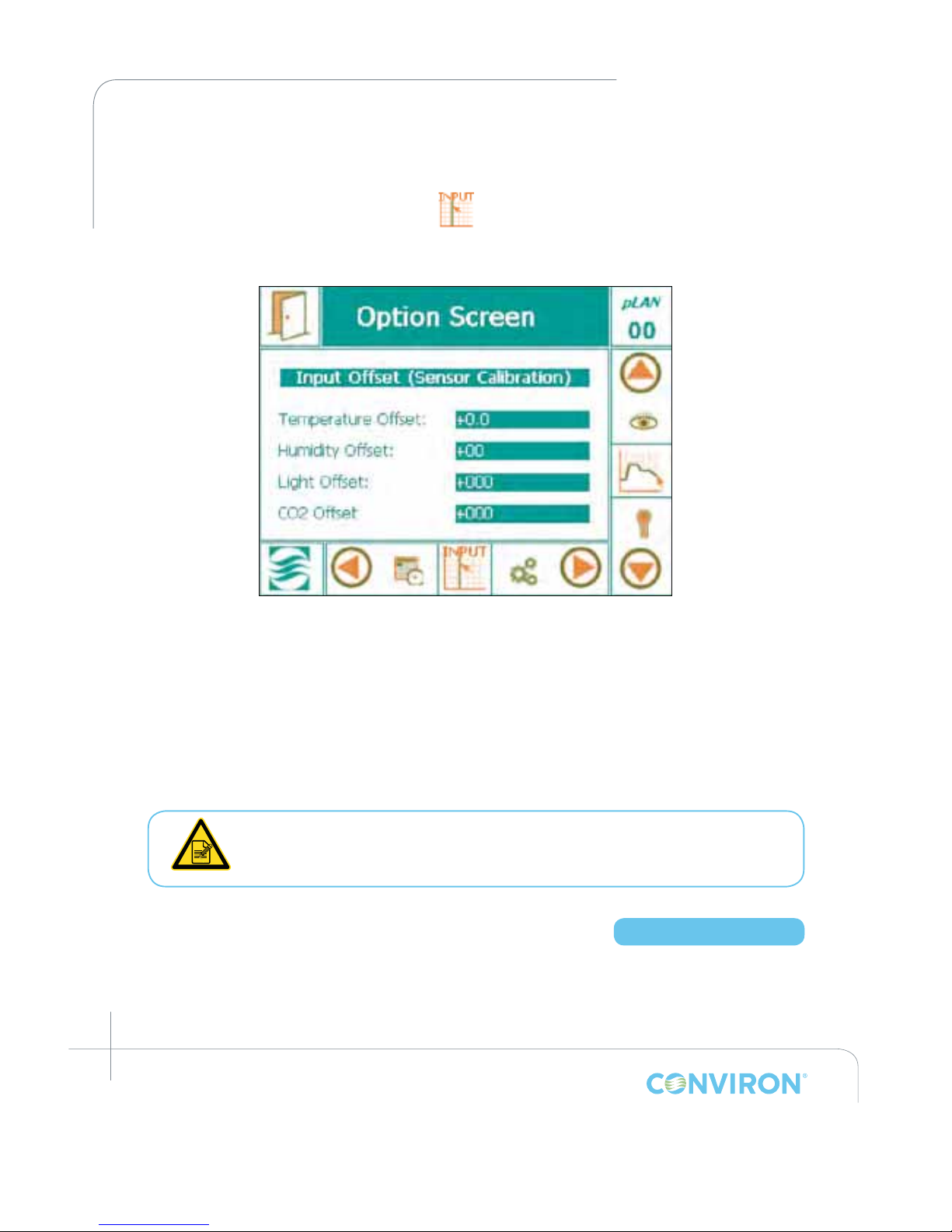
March 2015 | 253652R06
8-2
CHAPTER 8 | OPTION SCREEN
Offset correction is also useful since humidity sensors have a tendency to drift over time. In such
circumstances, the User can increase the offset correction to compensate for this. Conviron
recommends replacing the controller humidity sensor every two years.
To change the offset, tap the Input Offset icon in the main Option Screen to access the
Input Offset screen (Figure 8-2):
There are typically three (3) basic sensors installed in a chamber including Temperature,
Humidity, and Light. The CO
2
sensor is an optional component that appears below the light
sensor eld.
1. Tap the desired eld to modify the numerical data using the pop-up keypad (Figure 8-3). Tap
the OK button on the keypad when nished.
2. Repeat the process until all required offsets have been entered in the appropriate elds.
3. Tap the EXIT icon on the top, left hand side to store the values and exit to the Main
Status Screen.
If negative values are entered, there may be conict with alarm set-points,
specically with light and CO
2
, since they could reach values below 0.
8.3 (Chamber) Start-up Delay
For facilities that house multiple chambers, the CMP6050 offers a valuable feature called Startup Delay. This feature allows for the conguration of a power-on delay for each chamber which
staggers their start-up sequence. In the event of a power failure, once power is resumed,
chambers would start sequentially as opposed to all at once – an event that could cause an
Figure 8-2: Input Offset (sensor calibration)
Access Level 1
Page 67
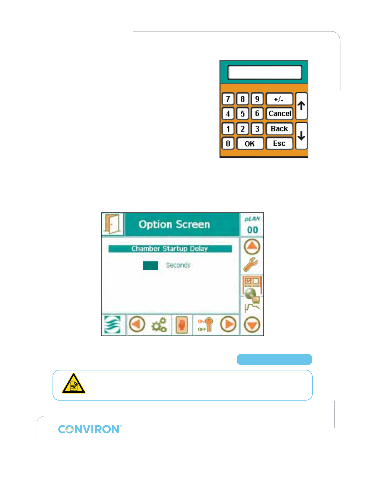
March 2015 | 253652R06
8-3
CHAPTER 8 | CMP6050 Operator’s Manual
undesirable power surge or, worse yet, another power
Figure 8-3: Keypad
failure. Conguring each chamber to start several
seconds after the previous chamber is a wise
precautionary step.
Conviron by default congures a random start-up delay
value between 1 and 59 seconds. To modify the default
value, tap the Start-up Delay icon in the Main Option
Screen to access the following screen (Figure 8-4:
Chamber Start-up Delay):
1. Tap the digit eld to access the pop-up numerical
keypad. (Figure 8-3)
2. Tap the desired number of seconds on the numerical
keypad. Conviron recommends a number between 10
and 59 seconds. When multiple chambers are present,
Conviron suggests setting this parameter 2 seconds apart.
3. Tap the OK button once nished. An alternative to using the electronic keypad is to use the
Keys on the right side of the display.
8.4 Time/Date
The Time / Date parameters were already setup in Section 3.0 Initial Start-up And
Navigation Overview. The operation does not need to be repeated here.
Figure 8-4: Chamber Start-up Delay
012
Access Level 1
Page 68
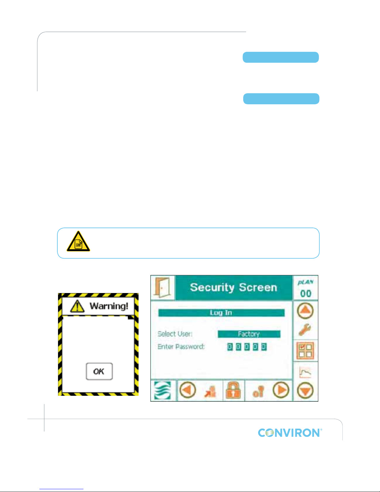
March 2015 | 253652R06
8-4
CHAPTER 8 | OPTION SCREEN
8.5 Setup
The Setup option screen designates the Data Storage Location for controller log data. This
option is factory set to Network and does not require modication by the User.
8.6 Security On/Off
Security features of the CMP6050 were already covered to some extent in Section 7: SECURITY
SCREEN, of this Manual. The focus in Section 7 was getting the Administrator and Users set up
with passwords, which is more of an infrequent (set-up) requirement. Security instructions provided
in this section of the Manual pertain more to daily security interactions with the controller. Note
that some instructions provided in this section may be redundant with those of Section 7.
The Security on/off feature is only available to the Administrator. When Security is turned OFF, all
users have access to all Level 1 and 2 features. When Security is turned ON, features are limited
by the access level (Level 1 for Users; Level 2 for Administrator).
With Security ON, anyone attempting to access a Level 1 or Level 2 screen will need to enter a
password (this is referred to as “logging in”). If a User (not the Administrator) is logged in and s/
he tries to access a Level 2 screen, a pop-up warning window appears (Figure 8-5) referencing
the need to login as an Administrator. Tapping the OK eld automatically brings up the Security
Login screen (Figure 8-6).
The Security icon located at the right side of the Bottom Menu Bar of the Main
Status Screen provides a shortcut to the Security Login Screen.
Access Level 1
Access Level 2
Access to this feature
requires “ADMIN”
status, please log in!
Figure 8-5: Warning
Pop-Up Window
1. Login per instructions in Section 7.5: Login Security Screen.
Figure 8-6: Security Login Screen
Page 69
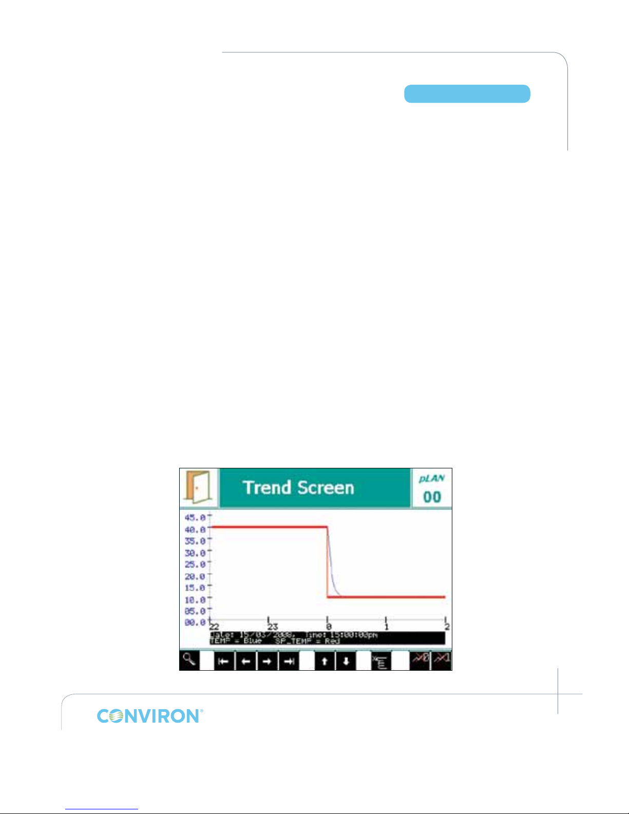
March 2015 | 253652R06
9-1
9.0 TREND SCREEN
Data management is an important aspect of controlled environment systems. Common is the
need for researchers to be able to view and assess their log data. In some cases, this is a critical
requirement. This section of the Manual is about Data Management. Key topics covered include;
• on-screen trend data, and
• log data downloadable over a network.
The CMP6050 employs a data logging feature that logs two data sets. One set of data is
viewable locally directly on the Display while the other set is viewable remotely via a networkconnected PC. The local data, viewable on the Display, is automatically logged every 18 seconds
and includes Temperature, Humidity, Light, and CO
2
(where applicable). The data is viewed in
the form of Trend Graphs (a charted history) on the Display (Figure 9-1: Trend Graph screen). The
controller has sufcient memory capacity to store 5 days worth of data after which it over-writes
the oldest data.
The remote data, viewable on a network-connected PC, is more substantial and includes
the log data for all I/O parameters. Again, the controller stores a package of data every
18 seconds, regardless of the number of parameters being logged. The data is stored
in memory as a text le with each le representing a 24-hour period. The le name used
has the format: ###.###.###.### YYYY-MM-DD.log which provides for convenient data
retrieval and management. The controller has sufcient storage capacity to store up to
approximately 20 days of data, depending on how many parameters are being stored for a
particular chamber conguration.
Given the capacity of the controller’s memory, it is recommended to extract the log data on a
weekly basis (Reference: Section 9.4 – Log Data – Network).
Access Level 1
Figure 9-1: Trend Graph screen
Page 70
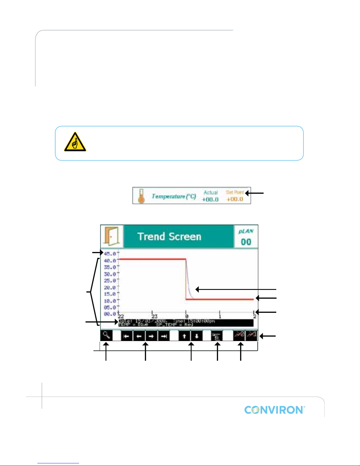
March 2015 | 253652R06
9-2
CHAPTER 9 | TREND SCREEN
To access the Trend Screen for any of the four (4) Key parameters (Temperature, Humidity, Light,
CO
2
) tap the desired parameter on the Main Status Screen. The example below (Figure 9-2)
shows the Trend Screen for Temperature.
LOCAL DISPLAY DATA
9.1 Trend Screen – Key Area Layout
When the controller memory has reached full capacity, by default, it will
overwrite the oldest data stored in the memory, without issuing a warning to
the User. To avoid losing data, Conviron strongly recommends to connect the
unit to a LAN system and utilize the CM Software.
To activate the Trend Screen, tap the Actual (green font) value of the desired parameter.
To update the graph press
Temperature
Parameter on Main
Status Screen
Bottom menu bar
Zoom Mode
"Go To"
Pan X-axis
Pan Y-axis
Screen
Pointer
Hide/Show
Actual
Figure 9-2: Trend Screen – Key Area Layout for Pan Mode
Y-Axis
Date/ Time
Display
Log Data
Trend Graph
Hide/Show
Set-Point
TimeAxis
Actual (blue)
Set-Point (red)
Page 71
March 2015 | 253652R06
9-3
CHAPTER 9 | CMP6050 Operator’s Manual
9.1.1 Pan Mode Screen Fields
Bottom Menu Bar
The Bottom Menu Bar displays all of the functions available with
Pan Mode.
Zoom Mode
Tap this icon to access magnication menus for the current trend screen.
Pan X-axis
Tap the outer left/right icons to move horizontally to the beginning or
end of the experimental data. Tap the left or right icons to view the
trend graph horizontally at specic intervals.
Pan Y-axis
Tap to pan the trend graph vertically.
Screen Pointer
Tap to activate – now tap anywhere on the trend graph screen to
view the data information with the tapped point moved to the
screen centre.
Hide/Show Actual
Tap this icon to hide or show the Actual data trend line.
Hide/Show Set-Point
Tap this icon to hide or show the Set-Point data trend line.
Actual
Actual trend line that the CMP6050 is showing (blue coloured line).
Set-Point
The trend line that the CMP6050 is programmed to follow per the
user’s program (red coloured line).
Axis
Depending on the trend graph, these values will change. For example,
temperature will indicate units in degrees Celsius while relative
humidity will indicate units measured as a %.
Time Axis
The Time Axis shows integers in units of time, and these units change
as you Pan.
To know what units the Time Axis is displaying
ensure you are viewing the Trend Screen in Pan
Mode (Figure 9-2) and then compare the Time
display (in the Date/Time eld) with the left-most
integer on the Time Axis. If the left-most integer
matches (for example) the minutes eld in the Date/
Time display, then the Time Axis is being display in
minutes. Notice that as you Pan to the right, both
the Date/Time display AND the left-most integer on
the Time Axis change simultaneously.
1
Date/Time Display
Depending on the trend graph being displayed, this display eld
shows the exact time and date synchronized to the trend displayed.
1
1
When using magnication (zoom), these values are adjusted automatically and in - sync with the Trend graph display.
Page 72
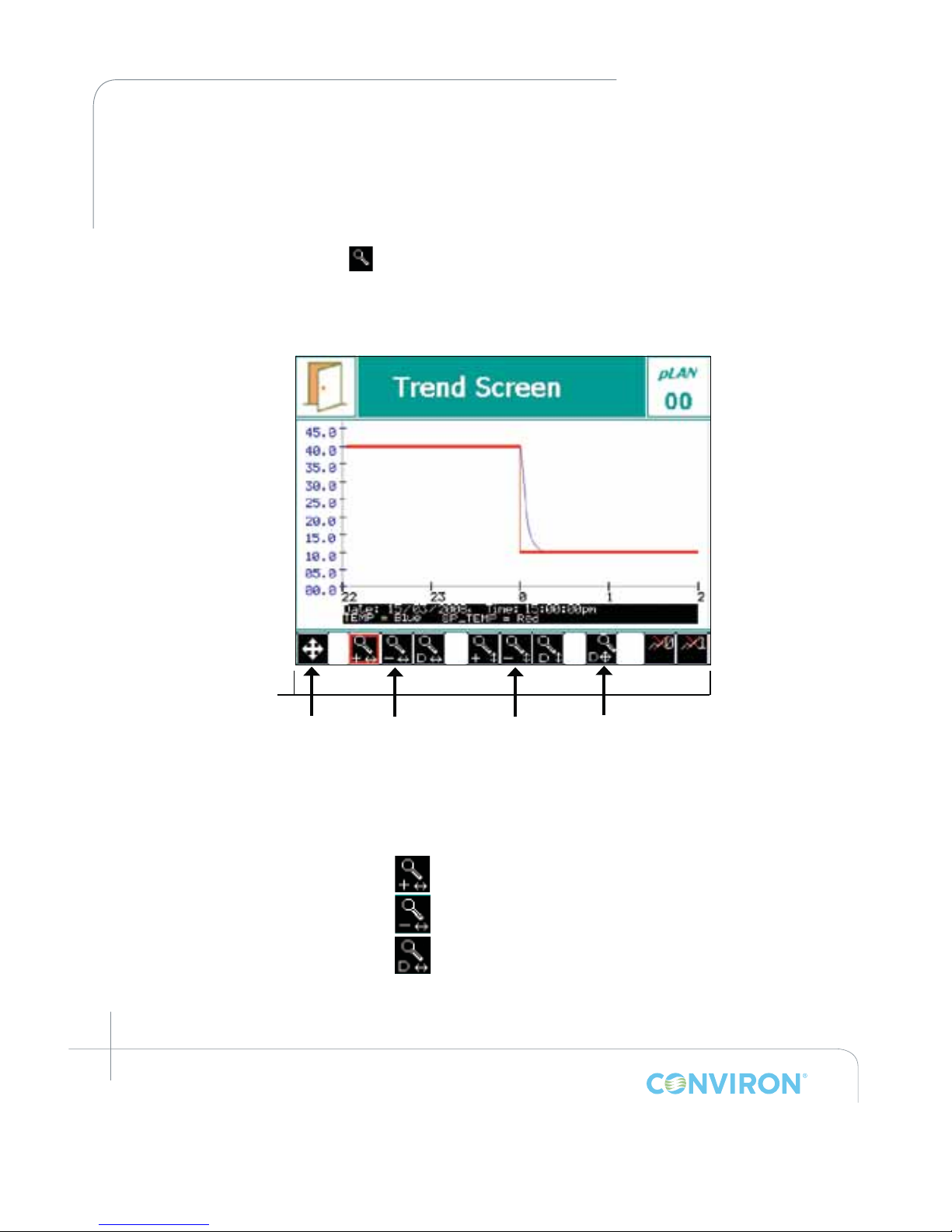
March 2015 | 253652R06
9-4
CHAPTER 9 | TREND SCREEN
Bottom Menu Bar
The bottom menu bar displays all the functions for
Zoom Mode.
Zoom X-axis
Tap the button to zoom in along the x-axis.
Tap the button to zoom out along the x-axis.
Tap the button to return to default zoom x-axis.
9.2 How to Pan on the Trend Screen
The Trend graph display can be panned left/right and up/down. To Pan right/left, tap the Pan
X-Axis buttons. To Pan up/down, use the Pan Y-Axis buttons.
9.3 How to Zoom on the Trend Screen
Tap the zoom mode button from the Pan Mode Screen to access the following Zoom Mode
screen: (same trend graph as Figure 9-1, but a different bottom menu bar)
9.3.1 Zoom Mode Screen Fields
Bottom menu bar
Pan Mode
"Go To"
Zoom X-axis
Zoom Y-axis
Return to
Default
Figure 9-3: Trend Screen - Key Area Layout for Zoom Mode
Page 73
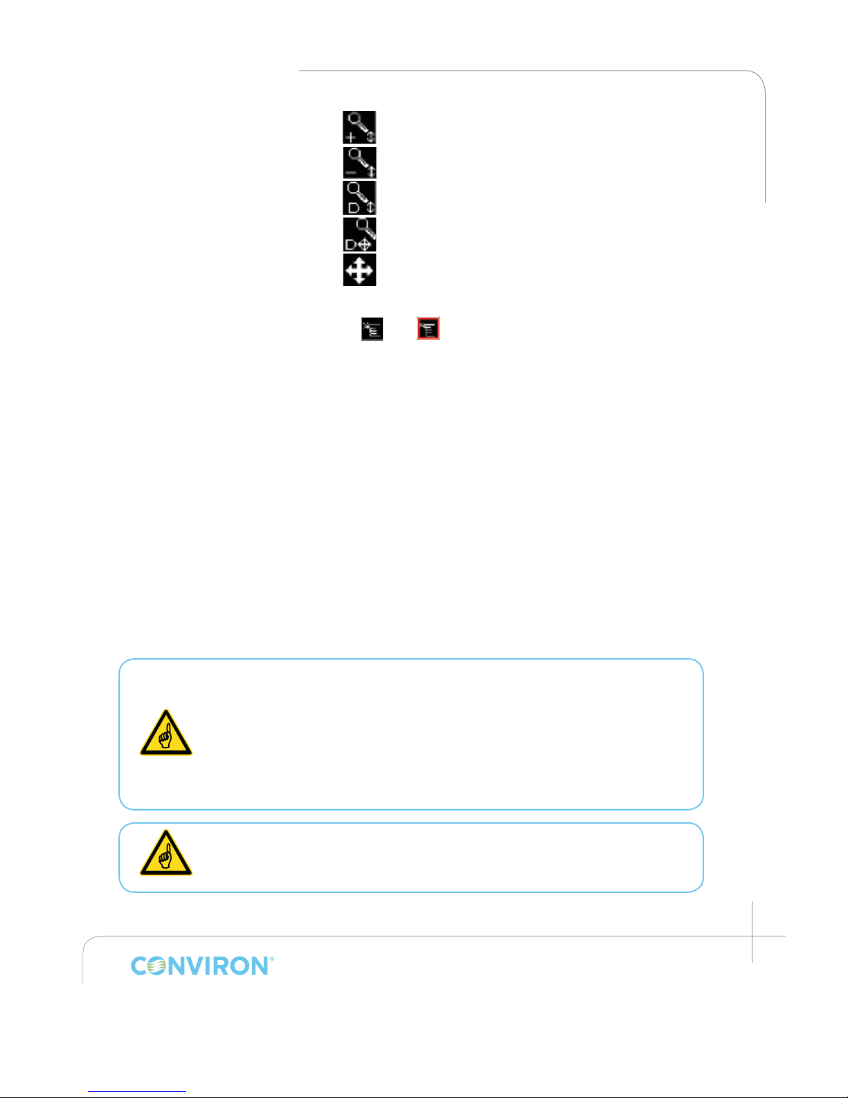
March 2015 | 253652R06
9-5
CHAPTER 9 | CMP6050 Operator’s Manual
Zoom Y-axis
Tap the button to zoom in along the y-axis.
Tap the button to zoom out along the y-axis.
Tap the button to return to default zoom y-axis.
Return to Default
Tap the button to return to default trend screen.
Pan Mode
Tap the button to return to Pan Mode.
The last button to be tapped will display a red perimeter
Example: to
REMOTE DATA
9.4 Logged Data – Network
The data available remotely is more detailed than on-screen data and includes every input
and output parameter being monitored and controlled. Data is automatically logged every 18
seconds regardless of the number of parameters. This provides exceptional data resolution for
the user and also benets service personnel.
The CMP6050 can be accessed with a network-connected PC from an FTP client to retrieve
log data or Conviron’s Central Management
™
System (Optional).
Three steps must be completed to access the CMP6050 logged data from a PC other than a
Central management system:
1. Setup the PC address
2. Set the CMP6050 controller address
3. Issue the FTP command in a Browser
Accessing data remotely typically requires assistance from the client's IT
department. Your computer may or may not be appropriately equipped to
access the CMP6050 remotely. [A computer requires a network card, an ethernet
cable (to connect via a network) or a cross-over cable (to connect directly to
a PC)]. Caution, if you set a TCP/IP address to the same value as another PC
on the network, you will disable both systems from network access. Firewall
security settings on your computer may inhibit or impair the performance of the
computer connection. Please consult your IT department for assistance.
Read the following instructions entirely before proceeding.
Page 74
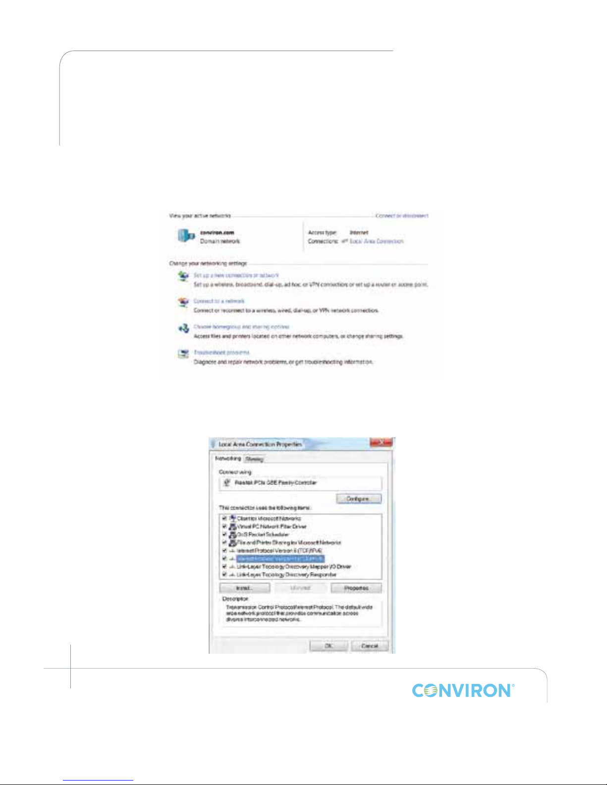
March 2015 | 253652R06
9-6
CHAPTER 9 | TREND SCREEN
To access the controller, it must be connected to a network. The network can be as simple
as connecting to a single PC or to a Local Area Network. There are two places where the
controller IP addresses must be setup - at the controller and at the connecting PC. If a Central
Management™ (CM) system is used, the CM address must also be dened.
9.4.1 Setting the IP address at the PC (for Windows 7 only)
1. Click on Start> Control Panel> Network and Internet > Network and Sharing Center. Click on the
Local Area Connection where the controller is connected (Figure 9-4).
Figure 9-4:
2. After clicking on Local Area Connection, click on Properties and scroll down and select
Internet Protocl (TCP/IPv4). Then click on Properties again. See Figure 9-5.
Figure 9-5:
Page 75
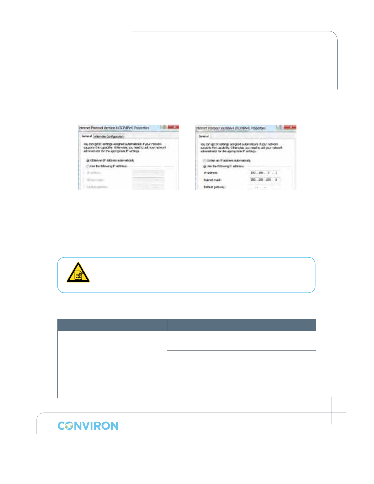
March 2015 | 253652R06
9-7
CHAPTER 9 | CMP6050 Operator’s Manual
3. Proceed as follows:
Step 1: The system has an IP that was automatically assigned by a DHCP server. In this
case, the property screen should look like the screen below and would automatically be
assigned. (Figure 9-6).
Step 2: If the IP was not automatically assigned the next step will be to configure the IP
address as in the screen below (Figure 9-7).
Figure 9-6: Internet Protocol (TCP/IP)
DHCP Addressing
Figure 9-7: Internet Protocol (TCP/IP)
Static Addressing
With either Option, if you are connecting to a "shared" local area network you must contact
your site's IT Administrator for a TCP/IP address that will be suitable to assign to the
CMP6050. This will ensure your PC and the CMP6050 are "address compatible".
If you are connecting directly to the chamber from the PC, you can safely set both TCP/IP
addresses without affecting other systems. Select the "Use the Following IP address" button and
type in the suggested address for the PC from the example below.
If you set a TCP/IP address to the same value as another PC on the network, you
will disable both systems from network access. You may have rewall security
settings on your computer that could inhibit or impair the performance of this
computer connection.
Conviron suggests the following basic conguration;
PC: CMP6050 Controller
TCP/IP Address: 192.168.0.1
Netmask: 255.255.255.0
#1
TCP/IP Address: 192.168.0.2
Netmask: 255.255.255.0
#2
TCP/IP Address: 192.168.0.3
Netmask: 255.255.255.0
#3
TCP/IP Address: 192.168.0.4
Netmask: 255.255.255.0
Etc.
Page 76
March 2015 | 253652R06
9-8
CHAPTER 9 | TREND SCREEN
9.4.2 Selecting an IP for the Controller
Set the controller address to the example on the previous page, if you are connected
directly to a PC or in the situation of a network connected PC, use the address supplied by
your IT network administrator.
To connect to PC: Use an ethernet cross-over cable to connect to the PC
To connect it to a network: Use standard ethernet cable
9.4.3 Setting the IP address at the Controller
There are two network addresses to set up in the CMP6050 as follows:
• CMP Address: Denes the identity of the controller within the network
• Netmask:
Divides an IP address into subnets
• CM Address: Conviron’s Central Management
TM
IP Address
A valid IP address is needed for the CM Address value only when there is
a Central Management system present. If there is no Central Management
system present, the CM Address should be set to Disabled.
This Section typically requires assistance from the client's IT department.
The following feature will give you a "Warning!"
pop-up window if the communication card on
the controller is not working. (Figure 9-8)
To set the Chamber Addressing:
1. From the Main Status Screen, tap the ID button
in
the Bottom Menu Bar to access the network conguration as
shown below:
Network card could
not be detected!
OK
Figure 9-8: Warning
pop-up window.
Page 77
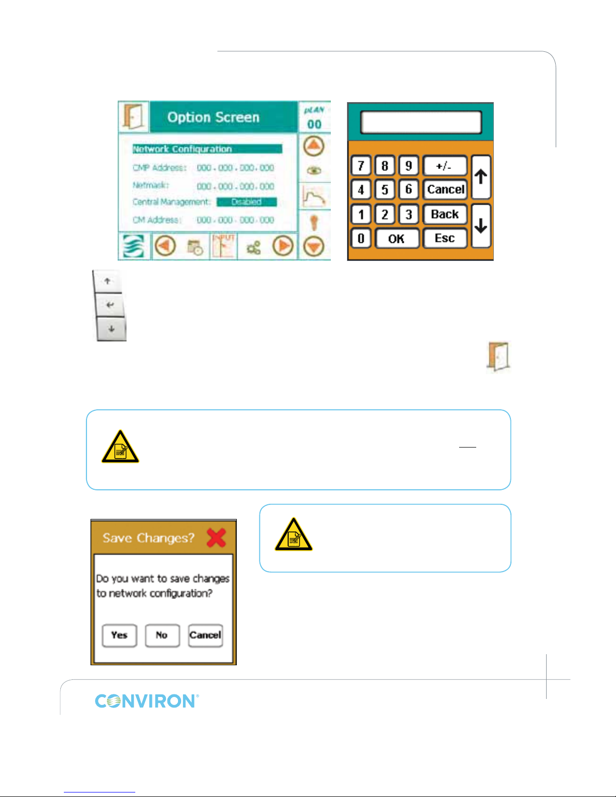
March 2015 | 253652R06
9-9
CHAPTER 9 | CMP6050 Operator’s Manual
Figure 9-9: Option Screen
Figure 9-10: Pop-up Keypad
2. To change the address numbers, tap each individual numerical eld. A
pop-up Keypad will appear each time a eld is accessed (Figure 9-10).
To enable the Central Management™ setting, tap Disabled then use
the K Up controller key as in Figure 9-11, to display Enabled and I
Enter to set.
3. Once all the addresses have been entered, tap the EXIT button
and a pop-up warning window will appear to conrm the
numerical entries (Figure 9-12).
4. Tap the Yes or No button to return to the Status Screen. Tap the Cancel button to reenter any numerical address errors.
Once the Chamber Addressing has been set, the Chamber ID displays the last
three digits of the CMP Address. If a Central Management system is installed,
the Chamber ID identifies the Chamber to the CM system. Duplicate IDs on the
CM system cannot be used, and no warning is issued. The Chamber ID's (last
3 digits) will also display in each of the respective chamber thumbnails on the
CM dashboard.
Figure 9-12: Conrmation Pop-Up
To congure additional Chambers
operating from the same controller,
tap the pLAN icon, select the
chamber number, and repeat steps
1-4 above.
Up
Enter
Down
Figure 9-11:
Controller Keys
Page 78
March 2015 | 253652R06
9-10
CHAPTER 9 | TREND SCREEN
9.4.4 Downloading logged data via FTP (for Windows 7 only)
1. Open an internet browser
2. Type in the address bar:
ftp://guest:[email protected]/usr/local/root/http/
Where xxx.yyy.www.zzz is the address of the controller.
3. The browser will display a long list of les, from which the one containing data is
generically called:
XXX.YYY.WWW.ZZZ Year-month-day.log
4. Copy the le into the folder where data is to be stored.
5. Using Microsoft® Excel or any similar application, search the le and open it.
The le was automatically saved as a .log (text) le which can be rapidly converted into a .xls
or . xlsx le for use in Microsoft® Excel.
6. To graph the variables, simply sort the table, remove the unneeded titles, and proceed with
the graph feature.
The text of XXX.YYY.WWW.ZZZ in the above lename and address is
actually a TCP/IP addresses. These will be different in each controller, as
addresses must be unique. Using the suggested Conviron address you
would substitute 192.168.0.1 for XXX.YYY.WWW.ZZZ.
Chambers should have the "ID" set, if the network log access is required.
The chamber ID identies (makes unique) the individual chamber's log les.
Page 79
March 2015 | 253652R06
10-1
10.0 SERVICE SCREEN
Service features have been available on Conviron control systems since the CMP4000 generation
and have provided a powerful, valuable, and effective tool. Primarily intended for interaction with
the control system by Conviron factory personnel and Conviron authorized service personnel,
the Service area provides the status of all controlled inputs and outputs of the chamber. Most
importantly, however, the Service area permits service personnel to override output variables
allowing for quick and effective troubleshooting in the eld.
The CMP6050 controller extends the Service capabilities of previous control systems by
providing features accessible to Users (minimum security level required is Access Level 1).
With the CMP6050, savvy Users can, with the support of Conviron’s service personnel, navigate
the Service Screen to determine why a unit is under-performing or malfunctioning. This,
together with the ability to manipulate output parameters, facilitates efcient and effective
troubleshooting which results in minimum chamber downtime and repair costs.
This Manual covers only the I/O Status area of the Security Screen. All
other areas are beyond the scope of this Manual and are restricted to
Access Level 3 personnel.
The Input and Output (I/O) parameters are congured for each chamber at the time of
manufacture based on the product model, design conguration, and client options. As such,
the I/O Status screen provides a list of the analog and digital input and output parameters
congured for the particular chamber.
The following section provides greater detail regarding the I/O Status Screen, specically as it
pertains to service/troubleshooting.
For safety reasons, interaction with the I/O Status screen is not available
remotely using Conviron’s Central Management system (previously named
CCS – Central Control System). As such, in order to manipulate any of the
output parameters from within the I/O Status screen, someone needs to be
physically present at the chamber to witness the chamber reactions.
When a Schedule is not running, Alarms are disabled! No one other than
a single, designated on-site service technician should be operating the
chamber. Altering output parameters to troubleshoot a chamber, while
others are handling mechanical or electrical systems within the chamber,
COULD BE HAZARDOUS AND MAY RESULT IN PERSONAL INJURY. As such,
manipulation of output parameters must be performed with either a qualied
service technician present or via phone support with Conviron’s Technical
Services group.
Page 80
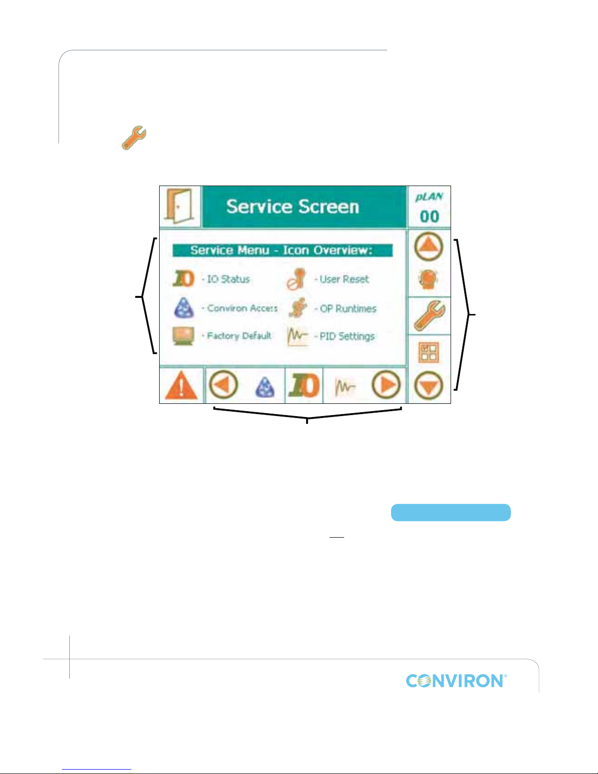
March 2015 | 253652R06
10-2
CHAPTER 10 | SERVICE SCREEN
10.1 Service Screen Icons
From the Main Status screen, scroll through the icons on the Main Menu Bar until the Service
icon appears in the active location. Tap the icon to launch the Service Screen (Figure
10-1: Service Screen).
The Service Menu shows six interactive icons. Of these, the
I/O Status
is the only one accessible
with User - Level 1 access. Tap the I/O Status icon to launch a series of screens that present the
status of all congured I/O parameters.
10.2 I/O Status
Figure 10-2 illustrates a sample I/O screen (schedule not running) showing several of the
congured Analog Input parameters for a particular chamber. Using the up and down
navigation Keys at the right of the display, scroll through the various screens to view the status
of all I/O parameters congured for that particular chamber. Only those parameters that have
been congured (at the Factory) for a particular chamber will be displayed. The parameters
are always displayed in the following order:
Figure 10-1: Service Screen
Service Screen
Main Menu
Main Menu Bar
Bottom Menu Bar
Access Level 1
Page 81
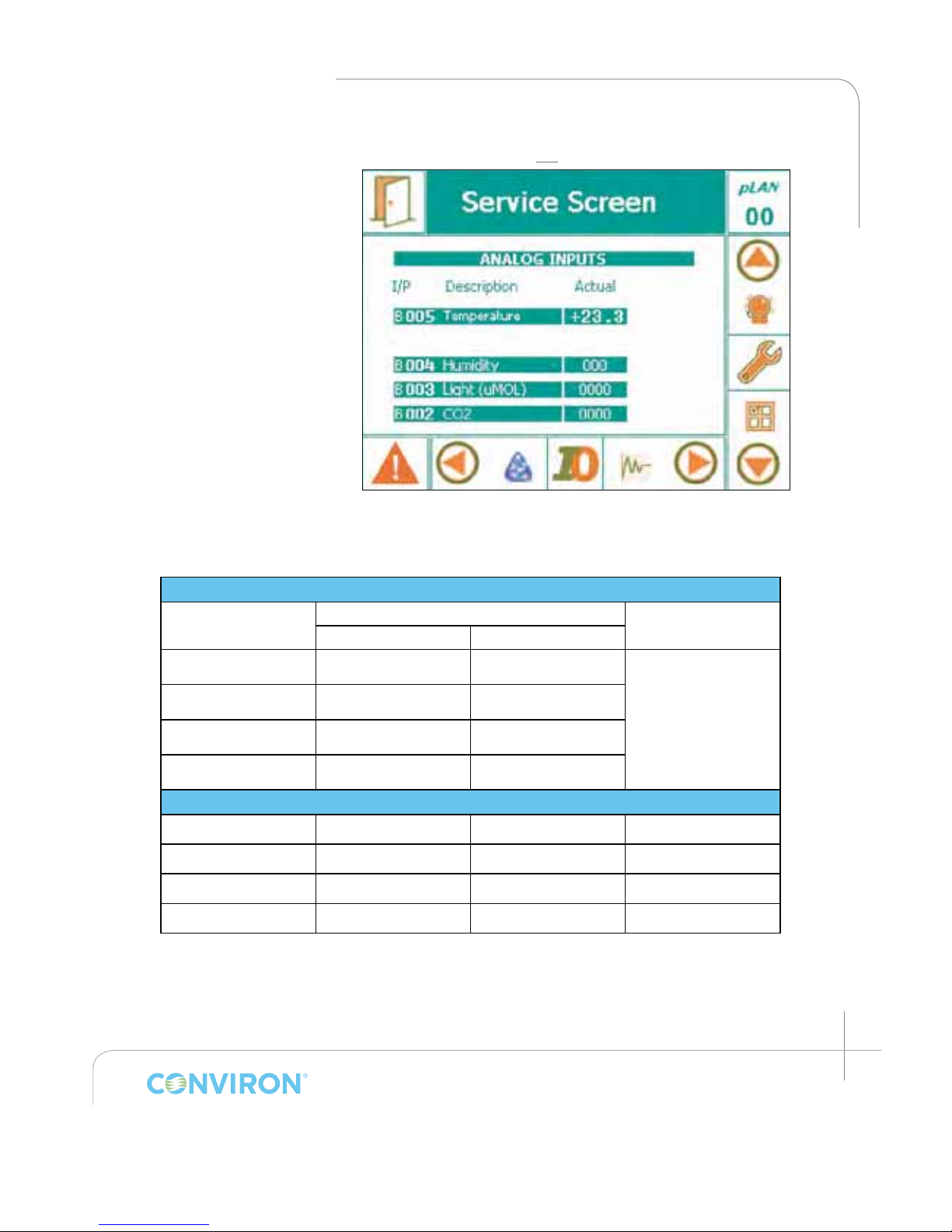
March 2015 | 253652R06
10-3
CHAPTER 10 | CMP6050 Operator’s Manual
• Analog Inputs
• Analog Outputs
• Digital Inputs
• Digital Outputs
The information presented
for each parameter type
and the corresponding
interactivity available
depends on whether or not
a schedule is running. The
following table summarizes
the I/O Status Screen
information and interactivity.
Figure 10-2: Sample I/O Screen - Analog Inputs ( Schedule
not running)
Table 10-1: Summary of I/O Status Screen Parameters
SCHEDULE RUNNING (Read-only mode)
I/O Type Display Interactivity
(Green) (Orange)
Analog Inputs Actual Value Set Point
Read-only when
schedule running.
No interactivity
allowed.
Analog Outputs Actual Value N/A
Digital Inputs Current Status N/A
Digital Outputs Current Status N/A
SCHEDULE NOT RUNNING (Troubleshooting mode)*
Analog Inputs Actual Value N/A No
Analog Outputs N/A Current Condition Yes
Digital Inputs Current Condition N/A No
Digital Outputs N/A Current Condition Yes
*Note: See Warning message – next page.
Page 82
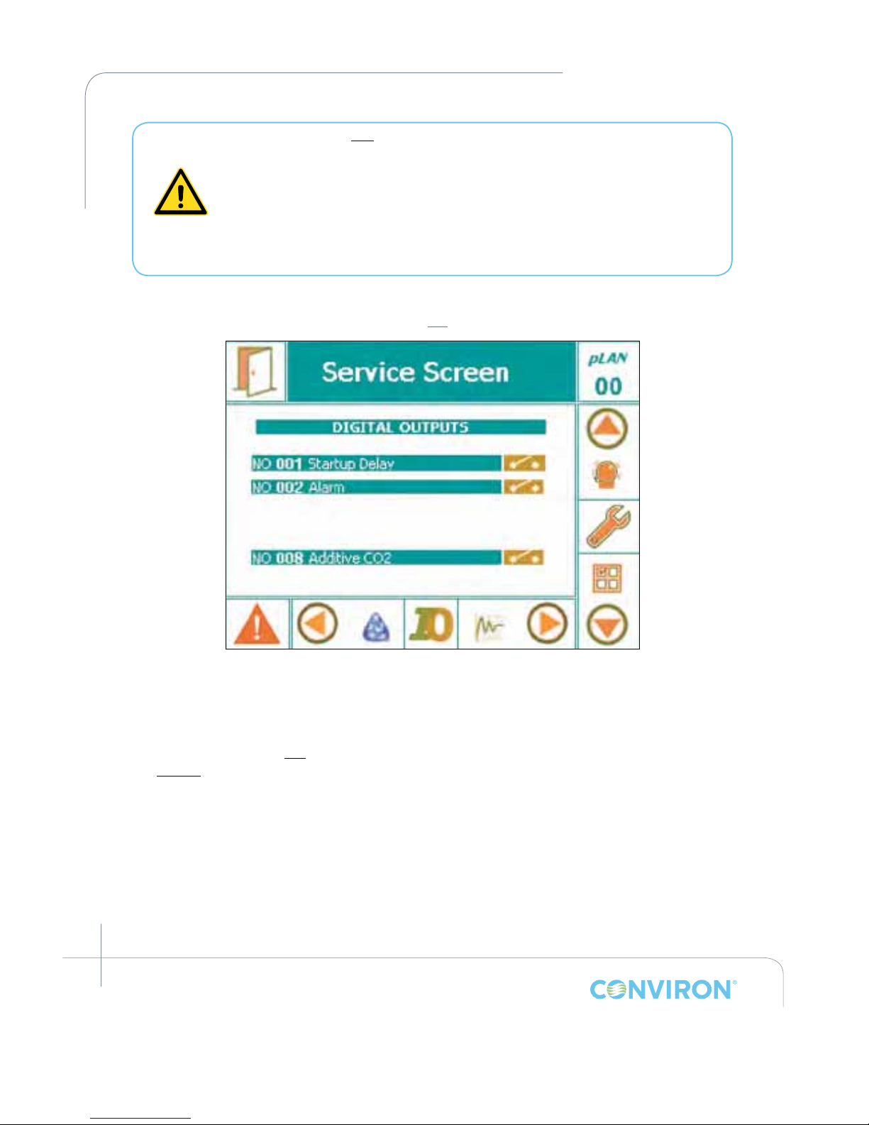
March 2015 | 253652R06
10-4
CHAPTER 10 | SERVICE SCREEN
When a Schedule is not running, Alarms are disabled! No one other than
a single, designated on-site service technician should be operating the
chamber. Altering output parameters to troubleshoot a chamber, while
others are handling mechanical or electrical systems within the chamber,
COULD BE HAZARDOUS AND MAY RESULT IN PERSONAL INJURY. As
such, manipulation of output parameters must be performed with either a
qualied service technician present or via phone support with Conviron’s
Technical Services group.
Figure 10-3: Sample I/O Screen - Digital Outputs
(Schedule not running)
From the table above, note the following:
• When a program is running, the I/O Status screen provides Read-only information regarding
the status of the I/O parameters – no interactivity is allowed.
• When a program is not running, the I/O Status screen allows analog and digital
output signals to be altered. This interactivity enables qualied service technicians
to troubleshoot the chamber. Refer to Figure 10-3 for a sample screenshot of Digital
Outputs. Note that the orange elds (when a Schedule is not running) can be altered.
(Note: Warning message above.)
To exit the I/O Status screen, tap the exit icon in the upper-left corner of the screen. When the
unit is running a Schedule (Read-only mode), this action simply returns to the Main Status Screen.
When the unit is not running a Schedule (Troubleshooting mode), this action will stop the unit.
Page 83

March 2015 | 253652R06
10-5
CHAPTER 10 | CMP6050 Operator’s Manual
10.3 Scalable Options:
One of the many impressive features of the CMP6050 is its scalability – that is, the ability
to expand the I/O capacity, congure optional devices, and add secondary controllers that
communicate with the main (primary) controller and the same (main) display. The following
represent available options also displayed on the I/O Status screen, where congured.
SENSORS – additional sensors can be added to the chamber and congured in the controller.
The (parameter) value of the additional sensors can be viewed at the I/O Status screen.
ADDITIONAL MODULES – For chambers that require the control of additional parameters,
expansion modules are added to the CMP6050 to increase the I/O capacity. In such
circumstances, the communication status and value of each additional parameter is displayed in
the I/O Status screen (appropriately as input/output, analog/digital) without differentiation from
those variables controlled by the main controller.
LAMP LOFT CONTROL - Units that require lamp loft control are equipped with a secondary
controller. The secondary controller communicates with the main (primary) control system
which records all lamp loft parameters as well. The status of the communication (On Line or
Disabled) and the variables being controlled are displayed in the I/O Status screen as well, in a
single screen.
CONTINUOUS DEFROST - As with the lamp loft control, this feature is also controlled by a
secondary controller. Communication status and parameter values are displayed in the I/O
Status screen.
IRRIGATION CONTROL - Automated watering of plants.
Page 84

March 2015 | 253652R06
A
GLOSSARY
Cell The individual entry points in the program table dened by the
intersection of any row (timeline) and any column (zone).
CCS Acronym for Central Control System. Now called Central
Management (CM).
Central Control System (CCS) A remote control and monitoring system available for
chambers with CMP6050 controllers. Contact Conviron Client
Services for more information.
Central Management
System (CM)
A remote control and monitoring system available for
chambers with CMP6050 controllers. Contact Conviron Client
Services for more information. Formerly called CCS.
Chamber The entire unit is called the chamber. Parts of the chamber
include the control screen, the electrical panel, the refrigeration
system and the plant growth area.
Controller The device that sets and records the conditions in the plant
growth area according to a user created program. The
CMP6050 is the latest generation controller.
Field box A specied area on the screen where data is displayed and/or
is entered.
Host Another term for the central control system. It is more commonly
used in alarm messages and technical documentation.
Inputs User dened parameters that enable controllers’ activity.
Ir33 Acts as a secondary fail-safe protector that shuts off the
chamber if its temperature limits are exceeded. The ir33 is set
by Conviron and is factory protected.
Latching The chamber does not recover and user intervention is
required. The alarm will stop the schedule and force the user to
manually re-start the chamber.
Non-Latching The chamber automatically recovers without human
intervention when the alarm conditions are corrected and/or
no longer active.
Outputs Switches that control specic devices or conditions within
the chamber.
Page 85
March 2015 | 253652R06
B
GLOSSARY
Plant growth area The environmentally controlled section of the chamber interior.
Program One or more timelines that create conditions in the growth
area during a 24-hour period. The timelines entered into the
Program Table indicate program conditions to the controller.
A multi-day program is a series of different programs,
scheduled together.
Program table
The series of columns and rows used for entering program
timelines on the Program screen.
RAMP mode
When conditions change gradually and steadily between
timelines, the CMP6050 works in RAMP mode.
RHS display buttons
Right hand side (RHS); Use these keys for entering controller
information and for navigational purposes.
STEP mode
When conditions are set to change dramatically between
timelines, the CMP6050 works in STEP mode.
Time line
Also referred to as "Lines", this is any single row in the
program table that contains a setting or settings that define
conditions in the plant growth area. For example, temperature
and relative humidity.
Schedule
One or more programs make up a schedule.
Menu bar/Tool bar
A series of buttons that usually displays at the bottom of the
screen. The buttons provide shortcuts to specific functions
such as on-line help, security and exit.
Page 86
Head Office
590 Berry Street | Winnipeg, MB | R3H 0R9
tel 204.786.6451 | toll free 1.800.363.6451 | fax 204.786.7736
Sales Office
PO Box 347 | Pembina, ND | 58271
toll free 1.800.363.6451 | fax 204.786.7736
Unit 1 Hall Barn Road Industrial Estate | Isleham, Cambridgeshire | CB7 5RJ | England
tel/fax +44 (0)1638 741112 | toll free +44 (0)800 0326422
Wulfsheinstr. 6 | 10585 Berlin | Germany
tel +49 (0) 30 - 315 05285 | fax +49 (0) 30 - 315 05286
Canada
USA
United Kingdom
Germany
www.conviron.com
CONVIRON IS AN ISO CERTIFIED COMPANY
 Loading...