

Page 1
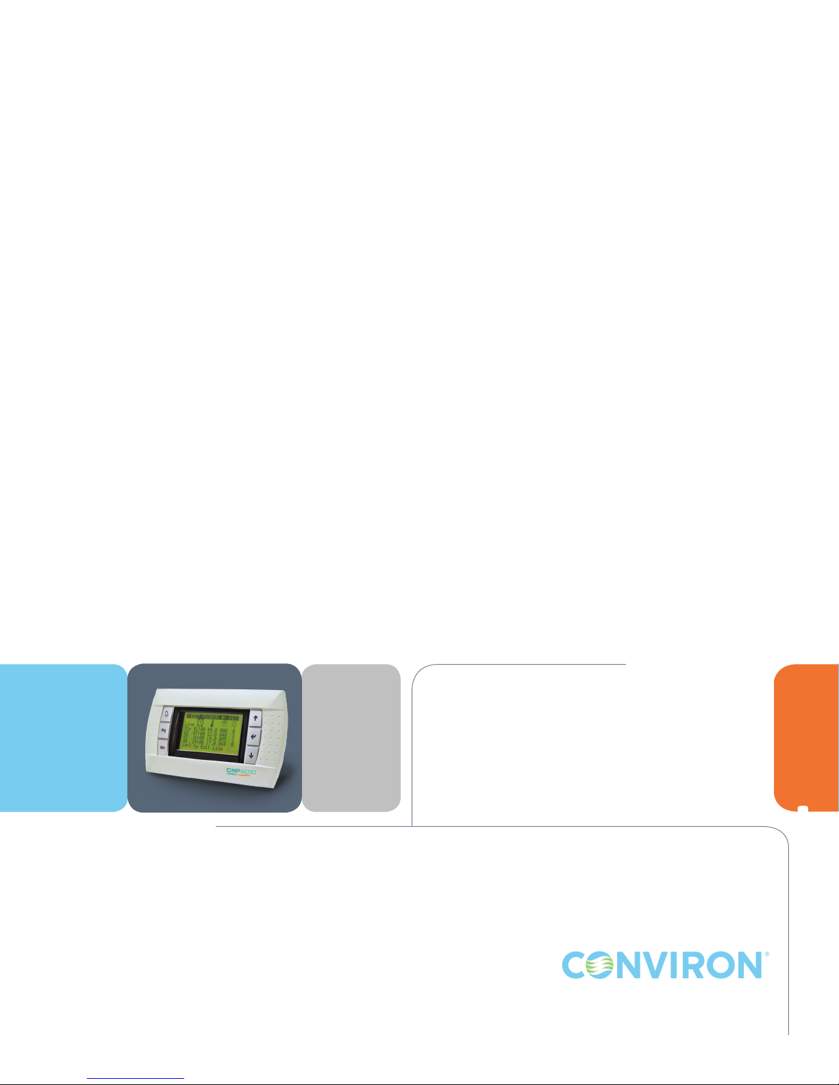
257249R04
CMP6010
USER MANUAL
Software Version 1.12
CMP6010
Page 2

Page 3

CMP6010
USER MANUAL
PLEASE READ THESE INSTRUCTIONS
CAREFULLY AND COMPLETELY
BEFORE OPERATING.
Conviron is a registered trademark of Controlled Environments Limited. All other trademarks are the property of their respective owners.
Information subject to change without written notice.
Published by:
CONVIRON
590 Berry Street
Winnipeg, Manitoba
Canada R3H 0R9
www.conviron.com
January 2016
Printed in Canada.
©2016 Controlled Environments Limited.
Page 4

Page 5

CONVIRON SERVICE AND TECHNICAL SUPPORT
Conviron welcomes the opportunity to provide assistance and to answer any technical questions related to
the start-up, use and troubleshooting of the CMP6010 control system. If you are having a problem using
your CMP6010, please ensure you have read this CMP6010 User Manual in its entirety for information
about the feature(s) with which you are experiencing trouble.
If the problem persists and/or you require additional assistance, please collect the following
information prior to contacting Conviron:
• The serial number of the chamber which is located on the rating plate on the side of the
chamber
• The software version number of the CMP6010 controller, which is located in the Help
screens. To access the Help screens, press the < > and < > hard keys at the same time
from the any of the three Status screens (temperature, humidity, or light)
• A description of the problem
• A description of what you were doing before the problem occurred.
Head ofce
Technical Services
Conviron
590 Berry St.
Winnipeg, Manitoba,
Canada R3H 0R9
Conviron Technical Services
North America Europe
Toll free +1.800.363.6451 +44.(0).800.032.6422
Telephone +1.204.786.6451 +44.(0).1638.781.731
Fax +1.204.786.7736 +44.1638.741.112
January 2016 | 256573R04
i
Page 6

Page 7

TABLE OF CONTENTS
PREFACE ................................................................................................................. xi
PRECAUTIONS ......................................................................................................13
1.0 CONTROLLER NAVIGATION .......................................................................1-1
1.1 User Interface ............................................................................................................................ 1-1
1.2 Button Functions ...................................................................................................................... 1-1
1.3 Menu Map ................................................................................................................................. 1-2
2.0 STATUS SCREENS ......................................................................................... 2-1
3.0 PROGRAM MENU ........................................................................................3-1
3.1 Introduction to Programs ........................................................................................................ 3-1
3.2 Creating a Program .................................................................................................................. 3-2
3.3 Editing a Program ..................................................................................................................... 3-4
3.4 Deleting a Program .................................................................................................................. 3-6
4.0 SCHEDULE MENU ........................................................................................4-1
4.1 Introduction to the Schedule .................................................................................................. 4-1
4.2 Schedule Hierarchy .................................................................................................................. 4-2
4.3 Creating or Editing the Schedule ........................................................................................... 4-3
4.4 Running the Schedule .............................................................................................................. 4-5
5.0 SECURITY MENU ..........................................................................................5-1
5.1 Logging In ................................................................................................................................. 5-1
5.2 Logging Out .............................................................................................................................. 5-3
5.3 Changing a Password .............................................................................................................. 5-4
6.0 ALARM MENU ..............................................................................................6-1
6.1 Changing Alarm Settings ........................................................................................................ 6-1
6.2 Viewing Alarm History .............................................................................................................. 6-1
6.3 Clearing Alarm History ............................................................................................................. 6-2
January 2016 | 256573R04
iii
Page 8

7.0 ALARM TROUBLESHOOTING ......................................................................7-1
7.1 Alarm State Indication ............................................................................................................. 7-1
7.2 Alarm Types ............................................................................................................................... 7-2
7.2.1 Viewing and Acknowledging an Alarm ........................................................... 7-2
7.2.2 Temperature Alarm: High Limit Exceeded (chamber: off) ............................ 7-2
7.2.3 Temperature Alarm: Low Limit Exceeded (chamber: off) ............................. 7-3
7.2.4 Humidity Alarm: High Limit Exceeded (chamber: on) ................................... 7-3
7.2.5 Humidity Alarm: Low Limit Exceeded (chamber: on) .................................... 7-4
7.2.6 Low Water Level (chamber: on, humidication system: off) .......................... 7-4
7.2.7 Door Open (chamber: on, humidication system: off) .................................. 7-4
7.2.8 High Pressure Alarm: Warning (chamber: on) ................................................ 7-5
7.2.9 High Pressure Alarm: Repeat (chamber: off) .................................................. 7-5
7.2.10 High Pressure Alarm: Time (chamber: off) ...................................................... 7-5
7.2.11 Low Pressure Alarm: Warning (chamber: on) ................................................. 7-6
7.2.12 Low Pressure Alarm: Repeat (chamber: off) ................................................... 7-6
7.2.13 Low Pressure Alarm: Time (chamber: off) ....................................................... 7-6
8.0 OPTIONS MENU ...........................................................................................8-1
8.1 Setting Time/Date .................................................................................................................... 8-1
8.2 Setting On-Delay ...................................................................................................................... 8-1
8.3 Enabling and Disabling Security ............................................................................................ 8-2
8.3.1 Enabling Security .............................................................................................. 8-2
8.3.2 Disabling Security ............................................................................................. 8-2
8.4 Setting Light Level and Input Offset ...................................................................................... 8-3
8.4.1 Setting Number of Discrete Light Levels ........................................................ 8-3
8.4.2 Setting Input Offset .......................................................................................... 8-4
8.5 Conguring Network Communication .................................................................................. 8-5
8.5.1 Inputting Network Communication Settings.................................................. 8-5
8.5.2 Connecting the Controller to a Network (LAN) ............................................. 8-6
8.5.3 Connecting the Controller to a Single Computer ......................................... 8-7
iv
Janaury 2016 | 256573R04
Page 9

9.0 SERVICE MENU ............................................................................................9-1
9.1 I/O Status ................................................................................................................................... 9-1
9.1.1 Accessing and Manipulating I/O Status Screens ........................................... 9-1
9.1.2 Controller Analog Inputs .................................................................................. 9-2
9.1.3 Controller Analog Outputs .............................................................................. 9-2
9.1.4 Controller Digital Inputs ................................................................................... 9-3
9.1.5 Controller Digital Outputs ............................................................................... 9-4
9.2 System ........................................................................................................................................ 9-6
9.3 PID Sets ...................................................................................................................................... 9-7
9.4 Cong .........................................................................................................................................9-8
9.4.1 Temperature Process Conguration ............................................................... 9-8
9.4.2 Humidity Process Conguration ...................................................................... 9-8
9.4.3 Carbon Dioxide Monitoring Conguration .................................................... 9-9
9.4.4 Alarm Type Conguration ................................................................................ 9-9
9.5 Reset User ................................................................................................................................ 9-10
10.0 GLOSSARY ................................................................................................10-1
January 2016 | 256573R04
v
Page 10

Page 11

PREFACE
This manual is intended for users of the CMP6010 control system. Although it is not intended as a
service manual, the Service menu of the controller and its functions are detailed as a reference for
service personnel.
The manual is presented in a visual format, using representative screen images to guide the user
through each set of instructions. The instructions proceed left-to-right and top-to-bottom, and are
augmented by arrows indicating movement from one step to the next. Text below each graphic
instructs the user in completing tasks, with required button presses indicated by angled brackets
containing the button’s graphic
For users viewing the manual electronically, navigation is simplied by the use of hyperlinks. Section
headings in the table of contents and gure/section cross-references within will take the user to the
relevant page in the manual when clicked or tapped. The user can return to the table of contents by
clicking or tapping the Conviron logo found at the bottom of each page.
< >
.
January 2016 | 256573R04
vii
Page 12

Page 13
PRECAUTIONS
The following symbols are used throughout this manual to draw your attention to important warnings,
guidelines and product information. Please take note of their respective meanings.
Hazard Warning Important Information
Dangerous Electrical Current Slippery Surface
Please note the following precautions before operating this equipment:
• This equipment is only to be operated and maintained by authorized personnel - that
is, personnel who have been trained on the proper operation and/or maintenance of
the equipment and who have read this manual.
• If in doubt about safe operation and/or maintenance of the equipment, contact the
responsible party in your organization immediately.
• Prior to operating, users should conduct a visual inspection of the equipment and
surrounding area by walking around the unit and checking both inside and outside
to ensure no debris or obstacles are present that could pose a safety hazard. If
operators see a potential hazard (e.g. water accumulating on the oor which could be
slippery or an obstruction that would prevent the door from opening/closing properly)
they should take appropriate steps such as alerting service personnel.
• Ensure that no one is using or could activate the room remotely during operation or
maintenance activities.
• When a Schedule is not running, Alarms are disabled! No one other than a single,
designated on-site service technician should be operating the chamber. Altering
output parameters to troubleshoot a chamber while others are handling mechanical
or electrical systems within the chamber, COULD BE HAZARDOUS AND MAY
RESULT IN PERSONAL INJURY. As such, manipulation of output parameters must be
performed with either a qualied service technician present or via phone support with
Conviron’s Technical Services group.
January 2016 | 256573R04
ix
Page 14
• Qualied trades-people such as electricians, plumbers, refrigeration mechanics, etc.
should perform all work as required by local codes and regulations.
• Central Management™ (CM) is an optional feature. If CM is being used it becomes
inextricably linked to the use of the Controller and therefore, both the Central
Management manual and the Controller Operators Manual must be read and
understood in their entirety prior to operation.
• Working in a high voltage environment will be required when servicing this
equipment. Do NOT attempt this work unless you have the appropriate knowledge
and experience. Always take appropriate safety precautions.
• The main terminal in the control panel has live voltage unless the external breaker is
OFF. Use extreme caution when working in the control panel to prevent injury.
• The Controller may come equipped with an optional Uninterrupted Power Supply (UPS)
such that power will remain live for a period of time even if the power supply is turned
OFF. Use extreme caution when working on the control panel to prevent injury. If you
have any doubts as to whether your unit comes equipped with a UPS, contact Conviron.
• Users should note that water may accumulate on the oor which could be slippery and
pose a safety hazard. Always ensure oors remain dry and wear non-slip footwear.
x
Janaury 2016 | 256573R04
Page 15
CHAPTER 1 | CMP6010 User Manual
1.0 CONTROLLER NAVIGATION
Using the current menu location (indicated at the top of every controller screen) and menu map
(located on the following page), it is easy for the user to navigate the controller interface.
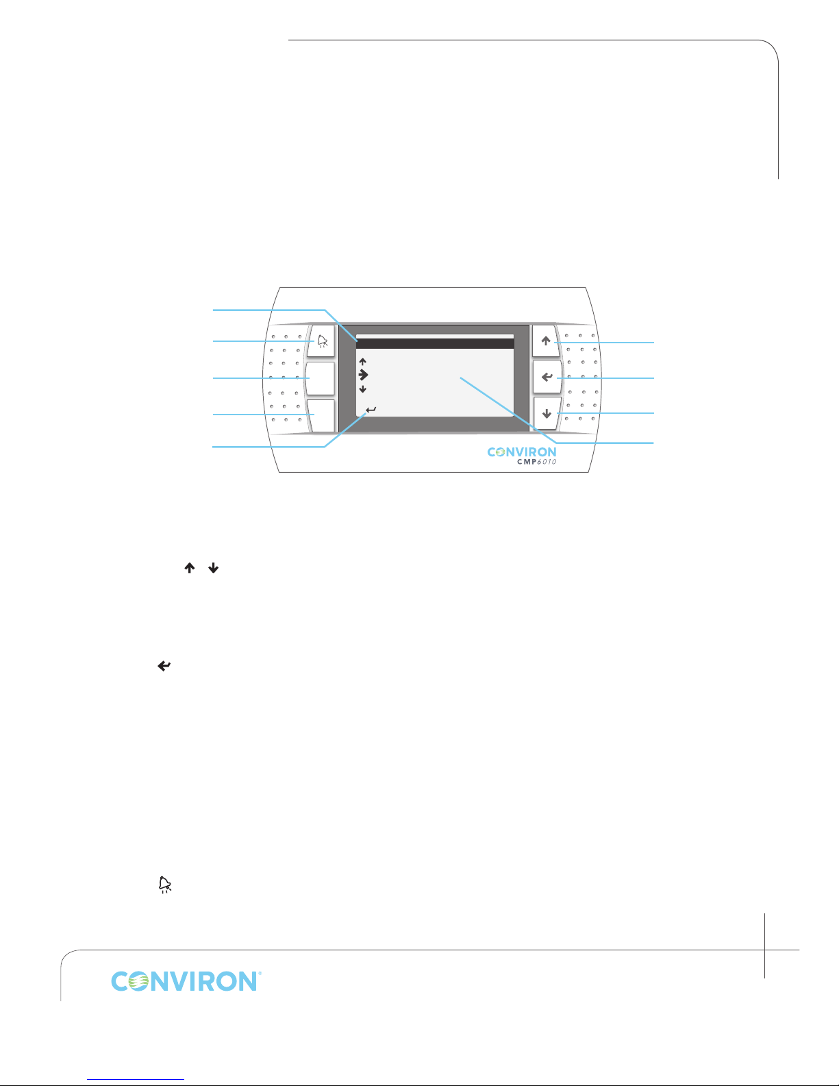
1.1 User Interface
Current
Menu Location
Alarm
Program
Escape
Menu Instruction
Prg
Esc
---MAIN MENU---
Status
Program
Security
< > to Select
Up
Enter
Down
Selected
Menu Item
1.2 Button Functions
Up/Down ( / ):
• Navigate between menu items
• Change the value of a congurable parameter
• Move to next screen (with cursor selecting menu location)
Enter ( )
• Open selected menu item
• Move cursor to the next congurable parameter on the page
Escape (
Program (
Alarm ( )
Esc
)
• Return to previous menu/screen
• Save schedule/program
Prg
)
• Flashes yellow to indicate when the schedule is running. When ashing, press to view running
schedule (from the Status screens only).
• Toggles between Edit-Add-Delete-Sort functions in Edit Program and Edit Schedule screens
• Flashes red to indicate an active unacknowledged alarm. Solid red indicates inactive
unacknowledged alarm. When illuminated (solid or ashing), press to view alarm.
January 2016 | 256573R04
1-1
Page 16
CHAPTER 1 | CONTROLLER NAVIGATION
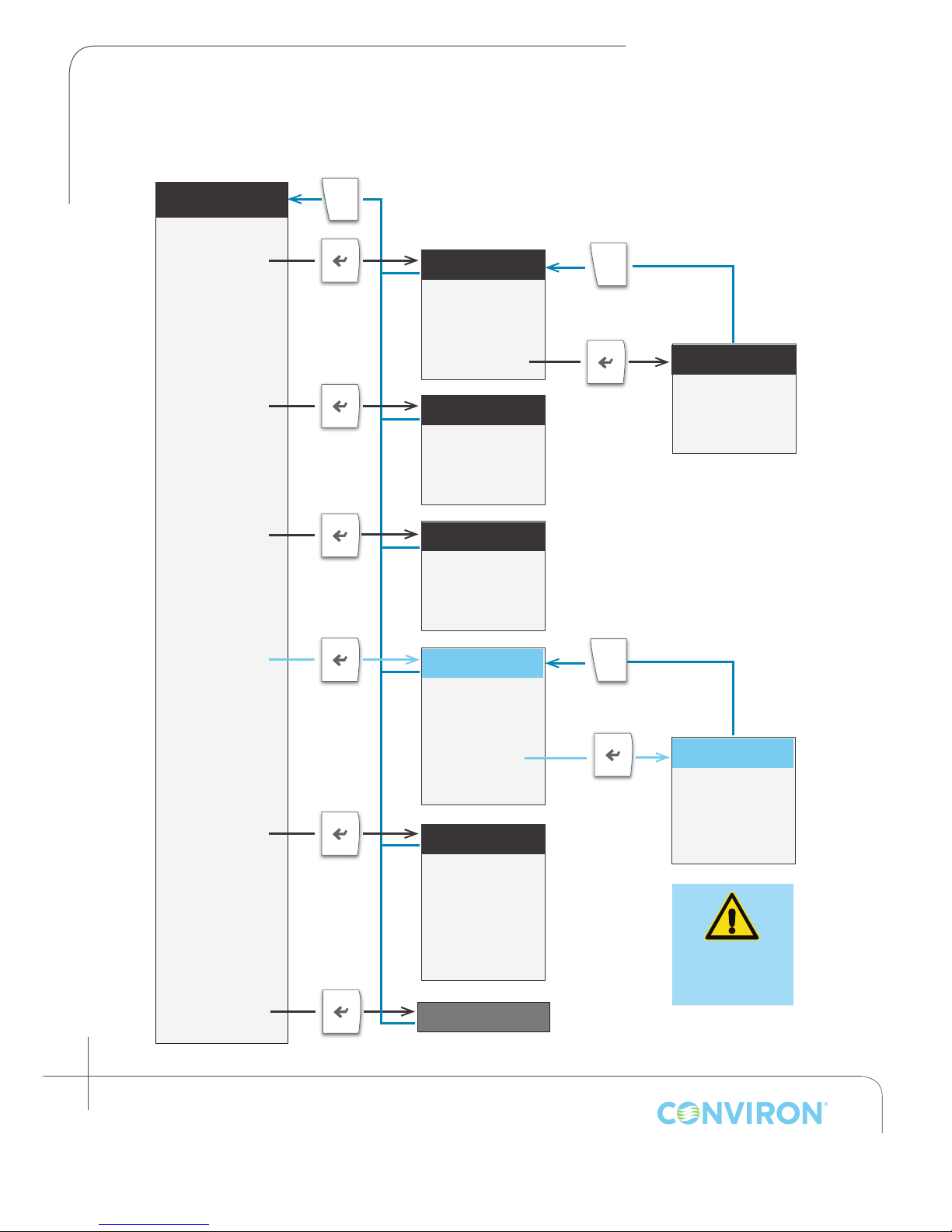
1.3 Menu Map
MAIN MENU
PROGRAM
SECURITY
ALARM
Esc
PROGRAM MENU
CREATE
DELETE
EDIT
SCHEDULE
SECURITY MENU
LOGIN
LOGOUT
PASSWORDS
ALARM MENU
SETTINGS
VIEW
CLEAR
Esc
SCHEDULE MENU
EDIT
CLEAR
RUN
1-2
Janaury 2016 | 256573R04
SERVICE
OPTIONS
STATUS
SERVICE MENU
IO STATUS
SYSTEM
PID SETS
CONFIG
RESET USER
OPTIONS MENU
TIME/DATE
ON DELAY
SECURITY
NETWORK
SETUP
STATUS SCREEN
Esc
CONFIG MENU
TEMP
ALARMS
HUM
MONITOR
AUTHORIZED
PERSONNEL
ONLY
Page 17
CHAPTER 2 | CMP6010 User Manual
< > for Main Menu
< > for Main menu
< > for Main menu
TEMPERATURE STATUS
< > for Main Menu
HUMIDITY STATUS
< > for Main menu
LIGHTING STATUS
< > for Main menu
< > for Main Menu
< > for Main menu
< > for Main menu
CO2 MONITORING
< > for Main Menu
< > for Main Menu
< > for Main Menu
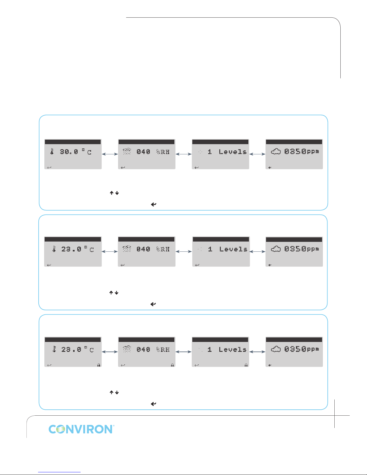
2.0 STATUS SCREENS
The Status screens display actual and set point conditions for the three controlled parameters:
temperature, relative humidity, and light level. Large type indicates actual measured values
(temperature, humidity) and current level (light), while smaller icons indicate set point values. A
padlock icon in the lower right of the screen indicates security has been enabled via the options
menu (if security is disabled no icon is present).
When the controller is powered on, it will display the temperature status screen by default.
Status Screens: Security Disabled, No Schedule Running
Optional
3 0. 0
Status screens displaying actual chamber conditions (large type). The absence of set point conditions indicates that the
< / > to toggle between temperature, relative humidity, and light level
0 40
Schedule is NOT running
< > to access the Main menu
1 Levels
0 350
Status Screens: Security Disabled, Schedule Running
Optional
TEMPERATURE STATUS
2 3 . 0
Setpoint 23.0
Status screens displaying actual chamber conditions (large type) and set point conditions (smaller type). The presence of set
< / > to toggle between temperature, relative humidity, and light level
HUMIDITY STATUS
0 40
Setpoint 040
point conditions (small type) indicates that the Schedule is running
< > to access the Main menu
LIGHTING STATUS
1 Levels
Setpoint 1
CO2 MONITORING
0 350
Status Screens: Security Enabled, Schedule Running
ppm
ppm
TEMPERATURE STATUS
2 3 . 0
Setpoint 23.0
Status screens displaying actual chamber conditions (large type) and set point conditions (smaller type). The presence of set
point conditions (small type) indicates that the Schedule is running. The padlock icon indicates that security has been enabled.
< / > to toggle between temperature, relative humidity, and light level
HUMIDITY STATUS
0 40
Setpoint 040
< > to access the Main menu
LIGHTING STATUS
1 Levels
Setpoint 1
Optional
CO2 MONITORING
0 350
January 2016 | 256573R04
ppm
2-1
Page 18

Page 19
CHAPTER 3 | CMP6010 User Manual
< > to Edit Line
3.0 PROGRAM MENU
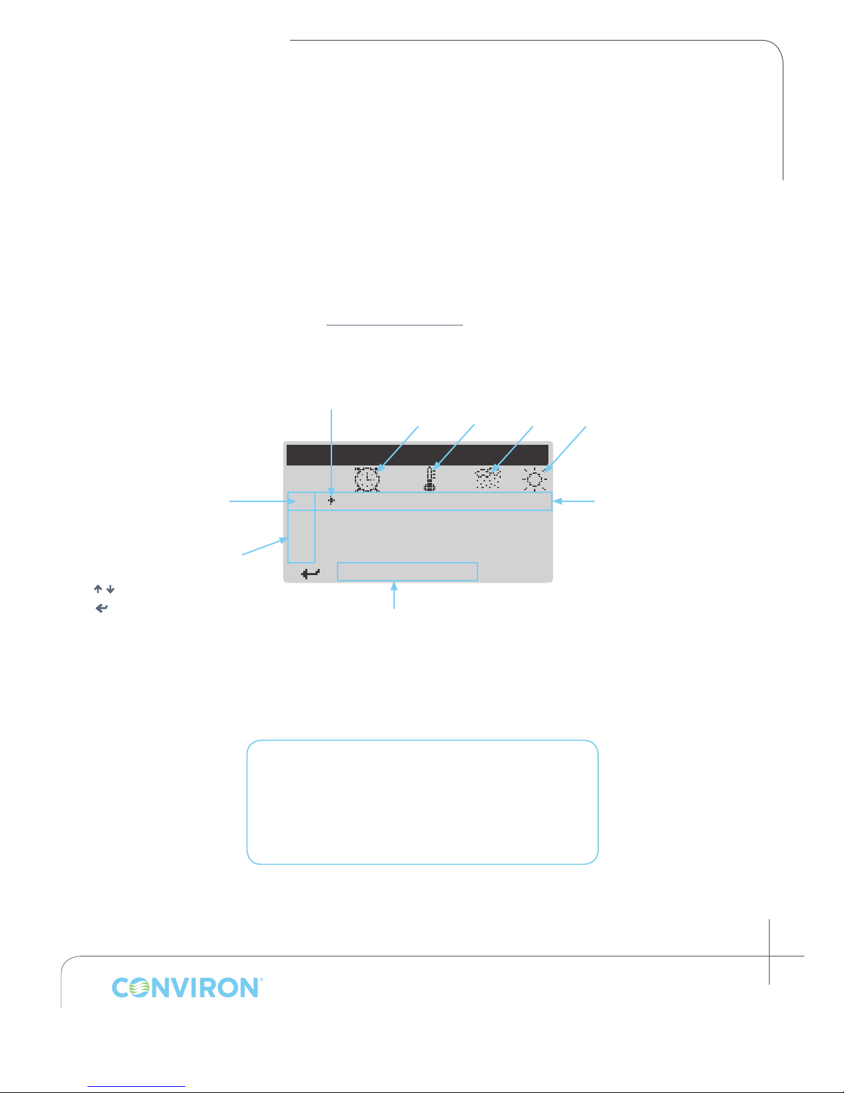
3.1 Introduction to Programs
A program is a list of timelines, each of which species chamber environmental conditions—
temperature, humidity, and light—for a specic point in time. Each program represents a single
24 hour period and can contain up to 24 timelines. The controller memory can store up to 16
programs. Programs are created and edited via the Edit Program screen, which can be accessed via
the Create and Edit menu items from the Program menu (dependent on whether you are creating a
new program or editing an existing program). Programs are then listed in the Schedule to dene an
experimental protocol (see section 4.0 SCHEDULE MENU).
Cursor
Timeline Number Column
< / > to change selected line
> to use selected function
<
Arrow Indicates
Chamber Set Point Value
Selected Line
Time; Temperature; Humidity; Light Level
EDIT PROGRAM #: 01
Line
{ 1 00 : 00 00 . 0 0 00 0
0 2
Currently Selected Function
<Prg> to toggle
Program Parameters:
Columns
Timeline (01)
Maximum Number of Programs per Controller: 16
Maximum Number of Timelines per Program: 24
Timeline Resolution: 1 minute
January 2016 | 256573R04
3-1
Page 20
CHAPTER 3 | PROGRAM MENU
< > to Add Line
< > to S elect
< > to Sort Program
< > to Delete Line
< > to Edit Line
< > to S elect
<Esc> t o Exit
< > to Edit Line
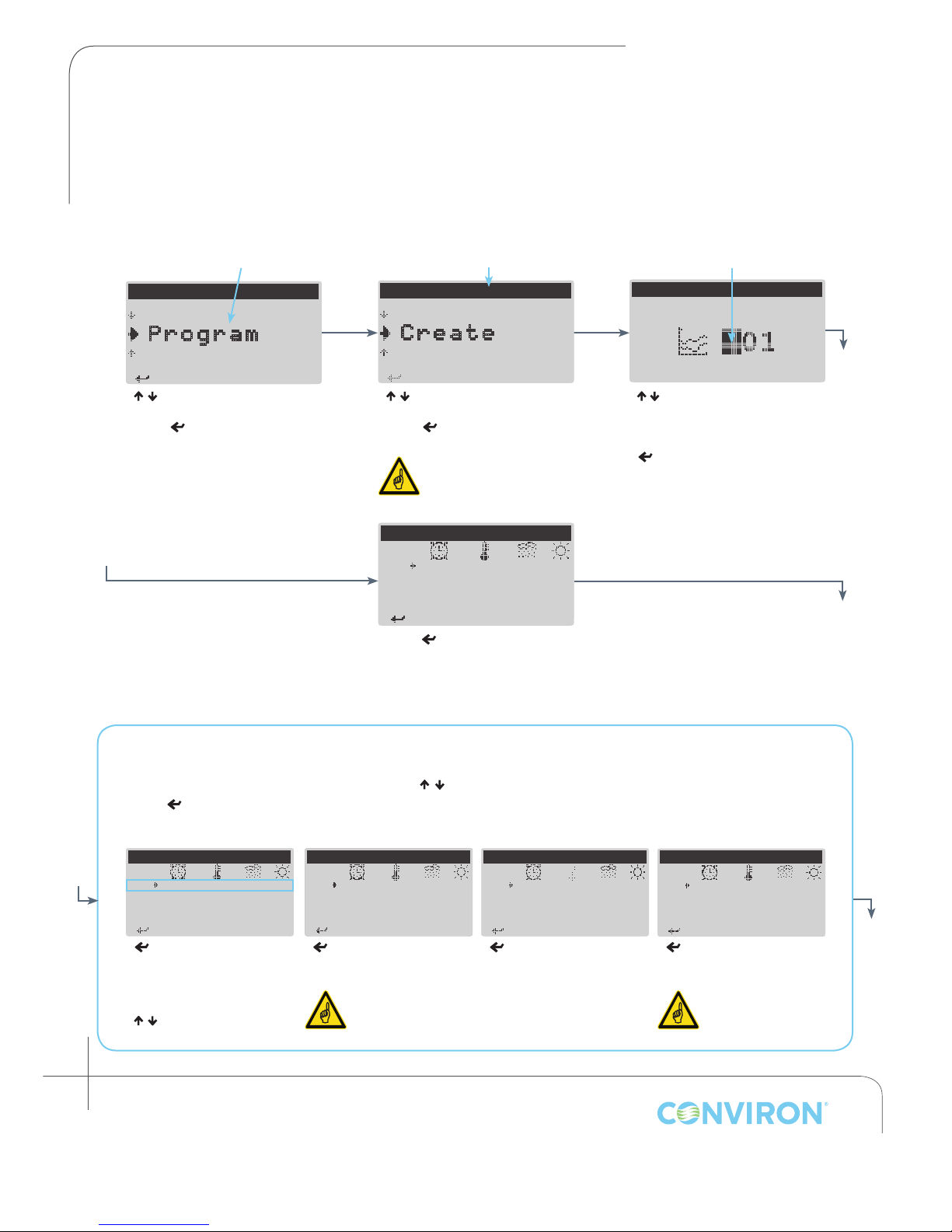
3.2 Creating a Program
Creating new programs using the CMP6010 interface is a simple procedure. The user must designate
a number under which to save the program, input desired set point values at their respective time
lines, and save the program once complete.
CursorSelected Menu Item Current Menu Location
---MAIN MENU---
S tatus
P rogram
S ecurity
< / > to select Program.
Enter < > to access the
Program menu.
---PROGRAM MENU---
S chedule
C reate
E dit
< / > to select Create.
Enter < > to access the Create
Program screen.
The controller can
store a maximum of 16
programs
CREATE PROGRAM
S ave new program as:
< / >
to designate program
number (controller default = lowest
available
< > to accept and access the
Edit Program screen
number from 1-16)
EDIT PROGRAM #: 01
Line
{ 1 00 : 0 0 0 0 .0 000 0
0 2
Press < > to add the rst
timeline to the program. The
controller will automatically
default to the Edit function as it
is the most commonly used.
There are four functions that can be used when creating and editing programs:
• Edit, Add, Delete, and Sort.
With the cursor in the Line column, Press < / > to select line, <Prg> to toggle between functions,
and
< >
to use the selected function.
Edit SortDeleteAdd
EDIT PROGRAM #: 01
Line
{ 1 00 : 00 00 . 0 00 0 0
0 2 05 : 0 0 15 .0 055 1
0 3 09 : 3 0 2 5 .0 06 0 3
0 4 14 : 0 0 22 .0 055 2
< > to move cursor leftto-right through set point
parameters for the selected
timeline
< / >
to adjust value of
selected parameter.
3-2
Janaury 2016 | 256573R04
Line
{ 1 00 : 00 00 . 0 00 0 0
0 2
< > to add a new timeline
at the current cursor position.
EDIT PROGRAM #: 01
Programs can
contain up to a
maximum of 24 lines.
EDIT PROGRAM #: 01
Line
{ 1 00 : 00 00 . 0 00 0 0
0 2
< > to delete a timeline at
the current cursor position.
EDIT PROGRAM #: 01
Line
{ 1 00 : 00 00 . 0 00 0 0
0 2
<
> to arrange the
timelines of the program in
chronological order.
Programs are
automatically
sorted when saved.
Page 21
< > t o continue
EDIT PROGRAM #: 01
< > to Edit Line
SAVE CHANGES
< > t o continue
< > t o continue
< > t o continue
W a r n i n g
< > t o continue
Line
{ 1 00 : 0 0 0 0 .0 000 0
0 2 05 : 0 0 15 .0 05 5 1
0 3 09 : 3 0 2 5 .0 0 60 3
0 4 14 : 0 0 22 . 0 05 5 2
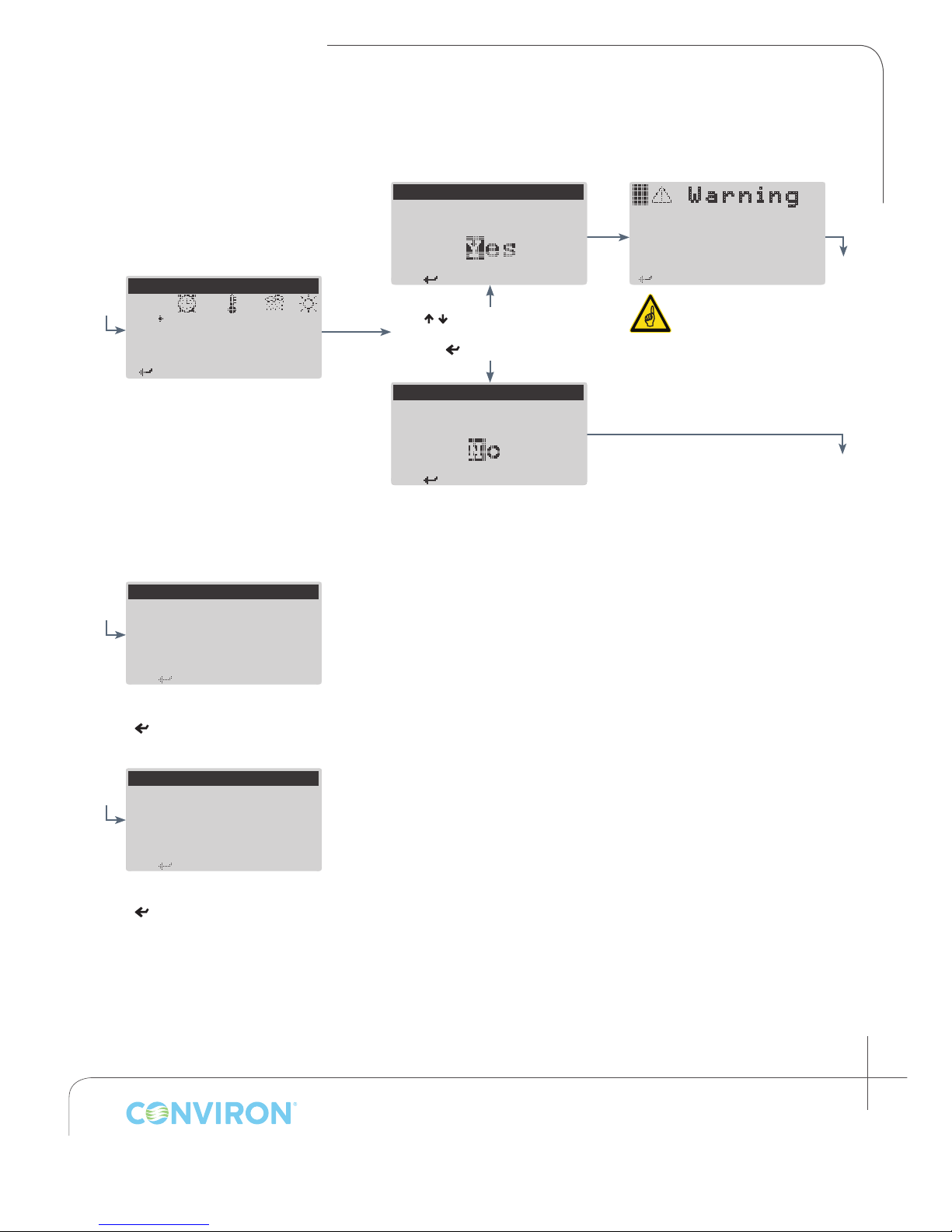
Once all timelines have been
entered/edited and the
program is complete, press
<Esc> to save changes
S ave changes to
program # 01?
< / > to select Yes or No
< > to continue
SAVE CHANGES
S ave changes to
program # 01?
CHAPTER 3 | CMP6010 User Manual
P rogram contains
duplicate time lines!
a
If the program contains
two or more timelines
which specify identical
times, the program will
not save until they are
resolved in the Edit
Program screen
b
PROGRAM SAVED
a
P rogram 01 saved.
Program has been saved
< > to continue and return to
Program menu
PROGRAM NOT SAVED
b
C hanges to program
#: 01 have been
discarded.
Program has
< > to continue and return to
Program menu
not
been saved
January 2016 | 256573R04
3-3
Page 22
CHAPTER 3 | PROGRAM MENU
< > t o continue
< > to S elect
< > to S elect
EDIT PROGRAM
<Esc> t o Exit
Select program number
< > to Add Line
< > to Sort Program
< > to Delete Line
< > to Edit Line
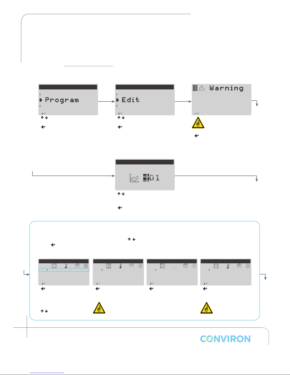
3.3 Editing a Program
The Edit menu item in the Program menu allows the user to make changes to an existing program.
The Edit Program screen is accessed from either the Create program or Edit program menu items
(see section 3.2 Creating a Program). The only difference is the Create menu item uses the Edit
Program screen to create a new program, while the Edit menu item allows the user to make changes
to an existing program only.
---MAIN MENU---
S tatus
P rogram
S ecurity
< / > to select Program
< > to access Program menu
---PROGRAM MENU---
C reate
E dit
D elete
< / > to select Edit
< > to access Edit Program
selection screen
< / > to select the number of the
program to be edited
< > to access Edit Program
screen
W a r n i n g
N o programs stored!
Use -create- from the
program menu.
If no programs are saved
the above warning will
be displayed
< > to continue and return to
the Program menu
There are four functions that can be used when creating and editing programs:
With the cursor in the Line column, Press < / > to select line, <Prg> to toggle between functions,
and
< >
EDIT PROGRAM #: 01
Line
{ 1 00 : 00 00 . 0 00 0 0
0 2 05 : 0 0 15 .0 055 1
0 3 09 : 3 0 2 5 .0 06 0 3
0 4 14 : 0 0 22 .0 055 2
< > to move cursor leftto-right through set point
parameters for the selected
timeline
< / >
selected parameter
3-4
Janaury 2016 | 256573R04
• Edit, Add, Delete, and Sort.
to use the selected function.
Edit SortDeleteAdd
EDIT PROGRAM #: 01
Line
{ 1 00 : 00 00 . 0 00 0 0
0 2
< > to add a new timeline
at the current cursor
position.
Programs can
to adjust value of
contain up to a
maximum of 24
lines
EDIT PROGRAM #: 01
Line
{ 1 00 : 00 00 . 0 00 0 0
0 2
< > to delete a timeline
at the current cursor
position.
EDIT PROGRAM #: 01
Line
{ 1 00 : 00 00 . 0 00 0 0
0 2
<
> to arrange the
timelines of the program in
chronological order.
Programs are
automatically sorted
upon saving.
Page 23
< > t o continue
EDIT PROGRAM #: 01
< > to Edit Line
SAVE CHANGES
< > t o continue
< > t o continue
< > t o continue
W a r n i n g
< > t o continue
Line
{ 1 00 : 0 0 0 0 .0 000 0
0 2 05 : 0 0 15 .0 05 5 1
0 3 09 : 3 0 2 5 .0 0 60 3
0 4 14 : 0 0 22 . 0 05 5 2
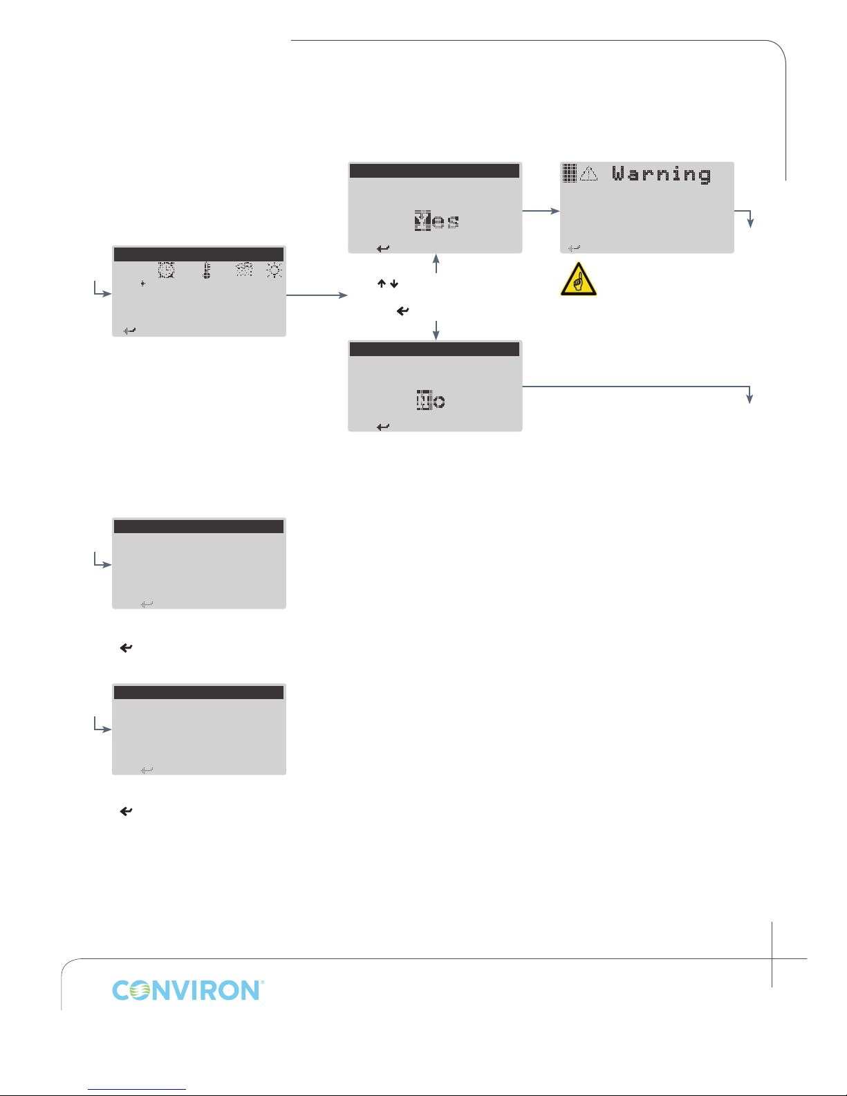
Once all timelines have been
entered/edited and the
program is complete, press
Escape <Esc> to save changes
S ave changes to
program # 01?
< / > to select Yes or No
< > to continue
SAVE CHANGES
S ave changes to
program # 01?
CHAPTER 3 | CMP6010 User Manual
P rogram contains
duplicate time lines!
a
If the program contains
two or more timelines
which specify identical
times, the program will
not save until they are
resolved in the Edit
Program screen
b
PROGRAM SAVED
a
P rogram 01 saved.
Program has been saved
< > to continue and return to
Program menu
PROGRAM NOT SAVED
b
C hanges to program
#: 01 have been
discarded.
Program has
< > to continue and return to
Program menu
not
been saved
January 2016 | 256573R04
3-5
Page 24
CHAPTER 3 | PROGRAM MENU
< > to S elect
< > to S elect
< > t o continue
<Esc> t o Exit
Select program number
A
to permanently delete
program number: 01?
< > t o continue
A
to permanently delete
program number: 01?
< > t o continue
DELETE PROGRAM
< > t o continue
< > t o continue
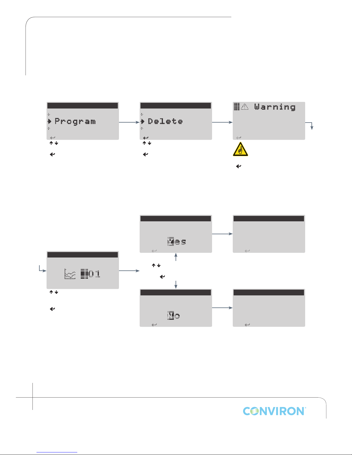
3.4 Deleting a Program
To delete a program, select Delete from the Program menu and identify the number of the program
to be deleted.
---MAIN MENU---
S tatus
P rogram
S ecurity
< / > to select Program
< > to access Program menu
DELETE PROGRAM
---PROGRAM MENU---
E dit
D elete
S chedule
< / > to select Delete
< > to access Delete
Program selection screen
DELETE PROGRAM
re you sure you want
< / > to select Yes or No
W a r n i n g
N o programs stored!
Use -create- from the
program menu.
If no programs are saved
the above warning will
be displayed
< > to continue and return to
the Program menu
DELETE PROGRAM
Program deleted.
< / > to select the number of the
program to be deleted
< > to accept
3-6
Janaury 2016 | 256573R04
< > to continue
DELETE PROGRAM
re you sure you want
Program restored.
Page 25
CHAPTER 4 | CMP6010 User Manual
4.0 SCHEDULE MENU
4.1 Introduction to the Schedule
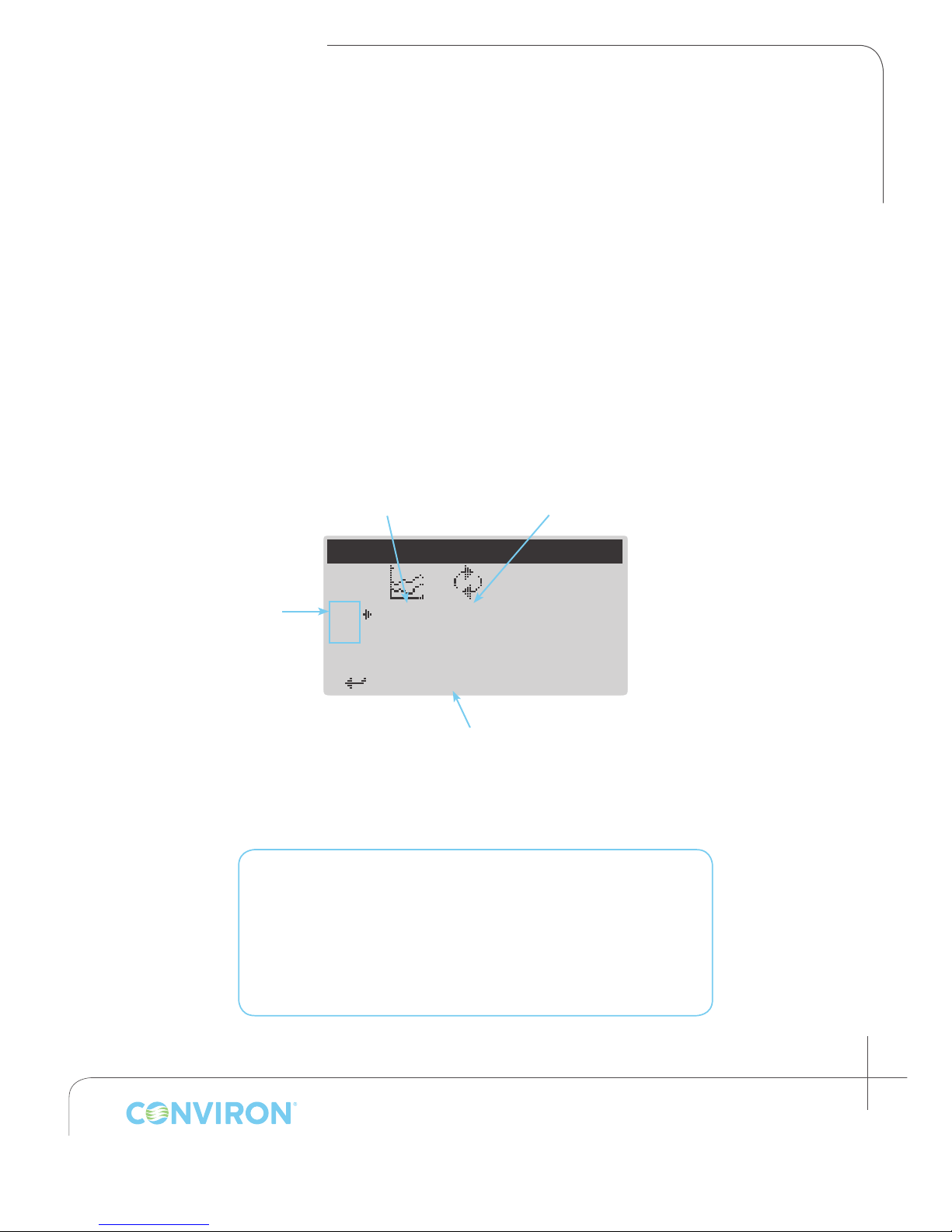
The schedule is a list of entries, with each entry designating a saved program and the number of
times for that program to run before moving to the next entry listed in the schedule. The CMP6010
controller can store one schedule. The schedule can contain up to eight entries, each of which can
be set for up to 99 repetitions, or set to run continuously (indicated by ∞ on the screen). In addition,
the entire schedule itself can be set for up to 99 repetitions, or set to run continuously.
The Edit Schedule screen uses the same functions as the Edit Program screen with the exception
of the Sort function, which is not necessary for editing the schedule as it is the order of the list that
determines the next program to be run rather than a specic time.
Number of Program
Program Number
Repetitions
Schedule Entry
Number
Maximum = 8
Schedule Parameters:
Maximum number of schedules per controller: 1
Maximum number of schedule entries: 8
Number of repetitions per entry: 1-99, or continuous (∞)
Number of schedule repetitions: 1-99, or continuous (∞)
EDIT SCHEDULE
0 1 1 7
0 2
< > to Edit Entry
Currently Selected Function
Press <Pgm> to toggle
January 2016 | 256573R04
4-1
Page 26
CHAPTER 4 | SCHEDULE MENU
4.2 Schedule Hierarchy
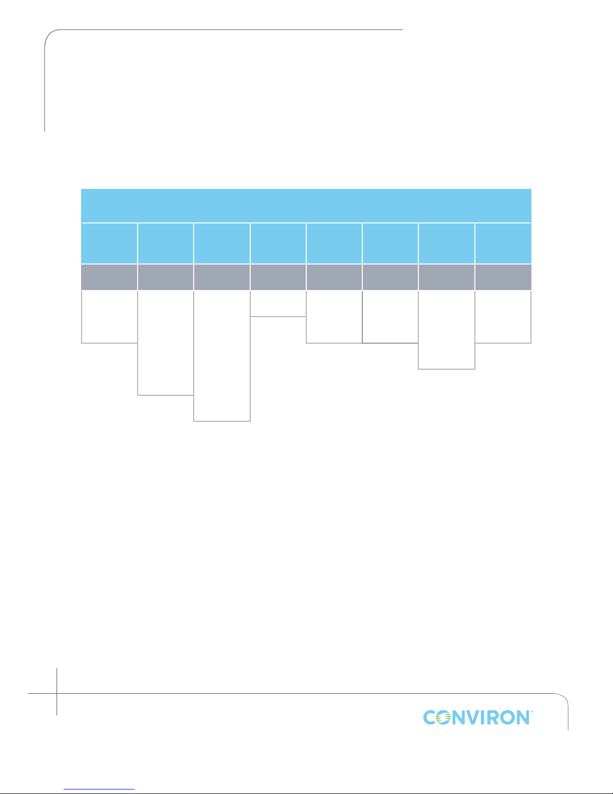
The table below illustrates the relationship between the Schedule and the Programs which comprise
the Schedule.
Schedule (0-99 Repetitions)
Entry 1
0-99
Repetitions
Program 1 Program 6 Program 4 Program 2 Program 3 Program 14 Program 11 Program 16
Timeline 1 Timeline 1 Timeline 1 Timeline 1 Timeline 1 Timeline 1 Timeline 1 Timeline 1
Timeline 2 Timeline 2 Timeline 2 Timeline 2 Timeline 2 Timeline 2 Timeline 2
Entry 2
0-99
Repetitions
Timeline 3 Timeline 3 Timeline 3
Timeline 4 ...
Entry 3
0-99
Repetitions
Timeline 24
Entry 4
0-99
Repetitions
Entry 5
0-99
Repetitions
Entry 6
0-99
Repetitions
Entry 7
0-99
Repetitions
Entry 8
0-99
Repetitions
4-2
Janaury 2016 | 256573R04
Page 27
CHAPTER 4 | CMP6010 User Manual
< > to Add Entry
< > to Edit Entry
< > to S elect
< > to S elect
< > to S elect
< > t o continue
< > to Delete Entry
4.3 Creating or Editing the Schedule
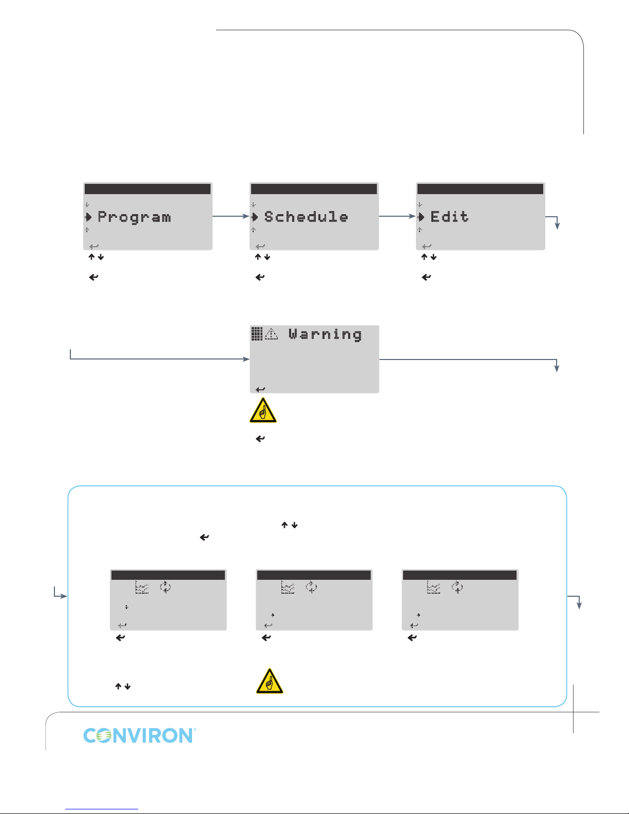
The process of creating and editing the schedule is very similar to the process of creating and editing
programs. The user must access the Edit Schedule screen from the Schedule menu, create or edit
the desired schedule entries, and save the schedule upon completion.
---MAIN MENU---
S tatus
P rogram
S ecurity
< / > to select Program
< > to access Program menu
---PROGRAM MENU---
D elete
S chedule
C reate
< / > to select Schedule
< > to access Schedule menu
W a r n i n g
No programs available
for scheduling!
Use -Create- from the
program menu.
If no programs are saved
the above warning will
be displayed
< > to continue and return to
Program menu
---SCHEDULE MENU---
R un
E dit
C lear
< / > to select Edit
< > to access Edit Schedule
screen
There are three functions that can be used when editing the schedule:
• Edit, Add, and Delete.
With the cursor in the entry column, Press < / > to select an schedule entry, <Prg> to toggle
between functions, and
< > to use the selected function.
Edit DeleteAdd
EDIT SCHEDULE
0 1 1 7
0 2 _ 0
< > to move cursor left-toright through program and
repetition parameters for the
selected entry
< / > to adjust value of
selected parameter
EDIT SCHEDULE
0 1 1 7
0 2 2 7
_ 3 0 0
< > to add a new entry at
the current cursor position.
The Schedule can
contain a maximum
of eight entries
EDIT SCHEDULE
0 1 1 7
0 2 2 7
_ 3 0 0
< > to delete an entry at
the current cursor position.
January 2016 | 256573R04
4-3
Page 28
CHAPTER 4 | SCHEDULE MENU
< > to Delete Entry
< > t o continue
schedule repeats
< > t o Continue
< > t o continue
< > t o continue
< > t o continue
< > t o continue
EDIT SCHEDULE
0 1 1 7
0 2 2 7
0 3 3 7
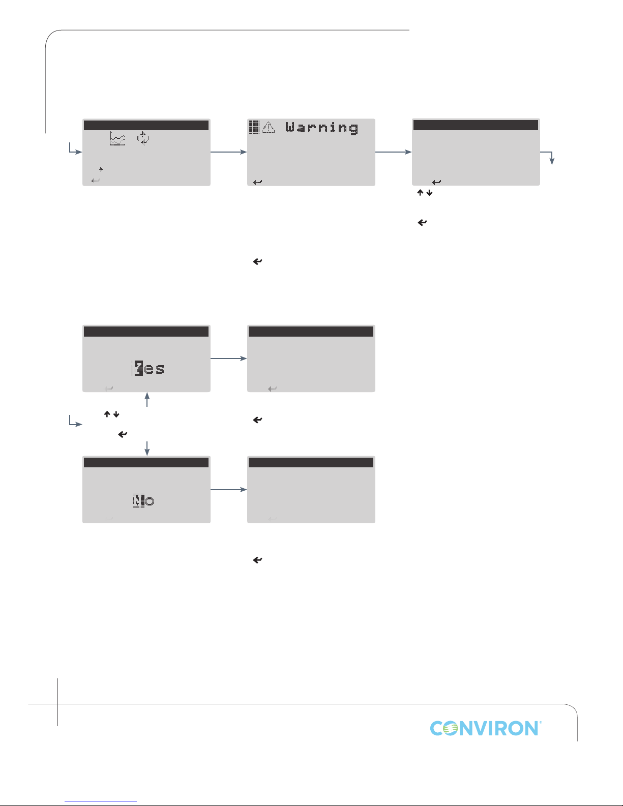
When creation/editing of the
schedule entries is complete, press
Escape <Esc> to designate the
number of times to repeat the
entire schedule.
SAVE CHANGES
Save changes to the
schedule?
< / > to select Yes or No
< > to continue
W a r n i n g
No programs available
for scheduling!
Use -Create- from the
program menu.
If any entries in the schedule
contain invalid program selections
(no program designated, or
designated program has been
deleted), the above warning will
appear.
< >
to continue and return to
the Edit Schedule screen.
SCHEDULE SAVED
Schedule saved.
Schedule has been saved
< > to continue and return to
the Schedule menu
EDIT SCHEDULE
Enter the number of
_1
/ > to select number of
<
schedule repetitions
< > to accept
Save changes to the
schedule?
4-4
Janaury 2016 | 256573R04
SAVE CHANGES
SCHEDULE NOT SAVED
Changes to schedule
have been discarded.
Schedule changes have
saved
< > to continue and return to
the Schedule menu
not
been
Page 29
CHAPTER 4 | CMP6010 User Manual
< > to S elect
< > to S elect
< > to S elect
< > t o continue
repeat number:
< > t o Continue
< > t o Continue
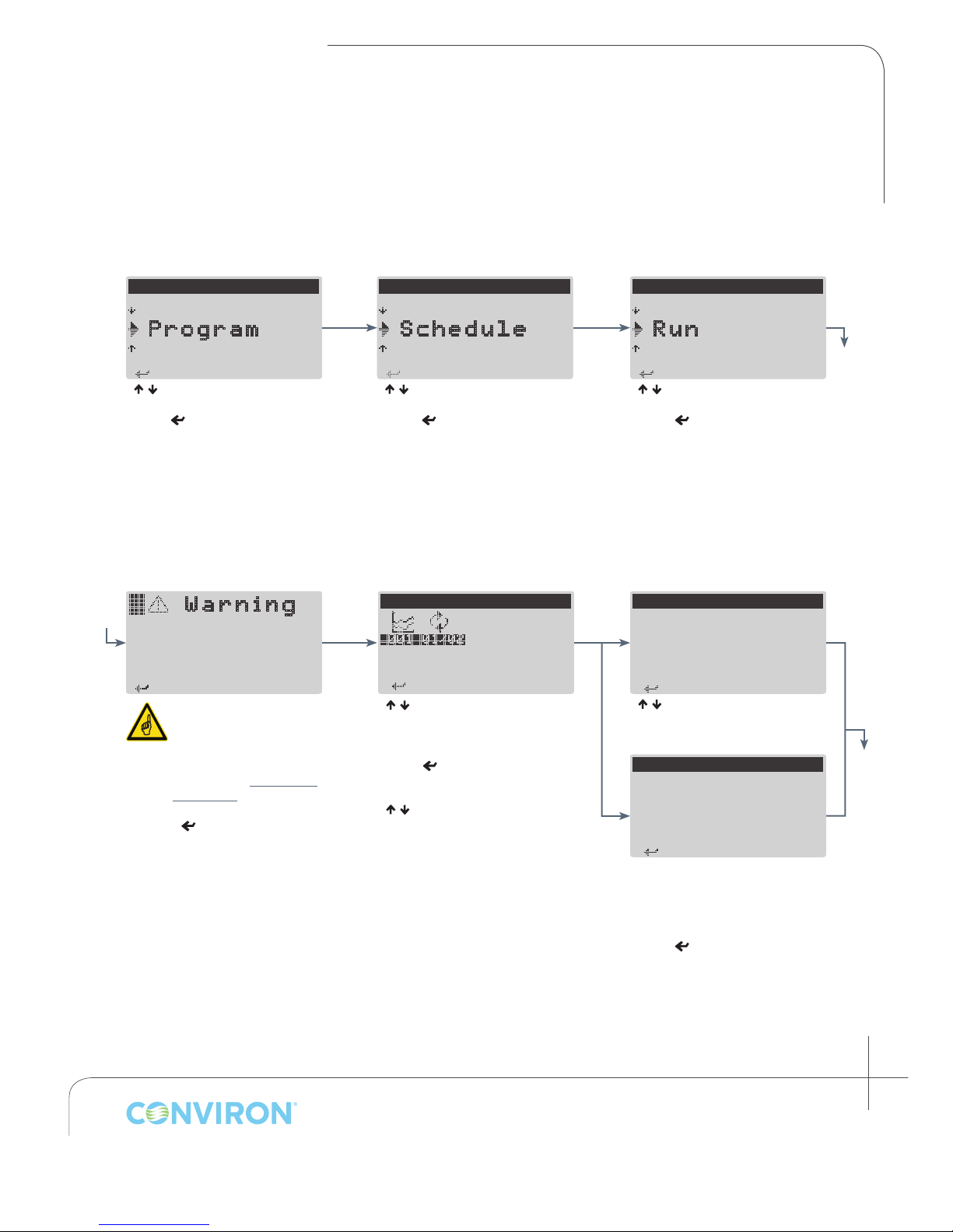
4.4 Running the Schedule
To run the schedule, a user has only to choose a starting point for the schedule and conrm that it is
ready to be run. The starting point can be any entry and repetition within the schedule.
---MAIN MENU---
S tatus
P rogram
S ecurity
< / > to select Program
Enter < > to access Program
menu
W a r n i n g
Time and date settings
should be verified
prior to running the
schedule!
Time and Date settings
should ALWAYS be
veried before running
the schedule to ensure
experimental integrity
(See section 8.1 Setting
Time/Date).
< > to continue to
Starting Entry screen
---PROGRAM MENU---
D elete
S chedule
C reate
< / > to select Schedule
Enter < > to access Schedule
menu
STARTING ENTRY/REPEAT:
02 02
< >-Edit, <Esc>-Save
< / > to select the entry from
which to start the Schedule (black
bar indicates starting Entry)
Enter < > to select starting
repetition for that entry
< / > to change starting
repetition
<
Esc
> to save and continue
---SCHEDULE MENU---
C lear
R un
E dit
< / > to select Run
Enter < > to access Starting
Entry screen
SCHEDULE REPEAT
Start schedule from
_1
< / > to select starting repetition
for the
ENTIRE
schedule
SCHEDULE REPEAT
Schedule is set to
continuous.
If the entire schedule was set
to run continuously (∞), the
message above will display as a
reminder to the user
Enter <
> to continue
January 2016 | 256573R04
4-5
Page 30
CHAPTER 4 | SCHEDULE MENU
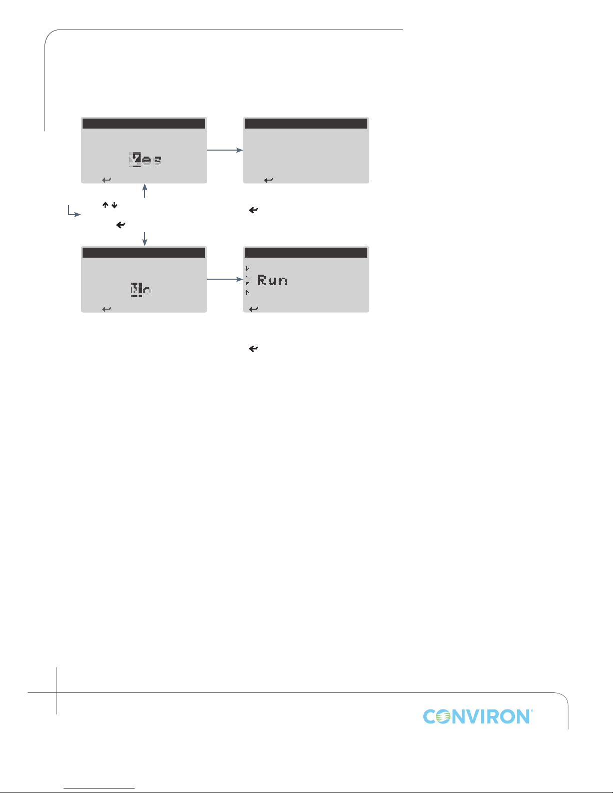
RUN SCHEDULE
< > t o continue
to run the schedule?
to run the schedule?
< > t o continue
< > t o continue
chedule started.
< > to S elect
Are you sure you want
< / > to select Yes or No
< > to continue
RUN SCHEDULE
Are you sure you want
RUN SCHEDULE
S
Schedule has been started
< > to continue and return to
the Schedule menu
---SCHEDULE MENU---
C lear
R un
E dit
Schedule changes have
saved
< > to continue and return to
the Schedule menu
not
been
4-6
Janaury 2016 | 256573R04
Page 31
CHAPTER 5 | CMP6010 User Manual
< > for Main Menu
5.0 SECURITY MENU
The Security menu allows the user to login, logout and modify user level passwords for the controller.
There are three security access levels possible: Factory, User and Public.
• Factory: Allows authorized/qualied personnel to access the Service menu. Factory level
security is
password is required
• User: Intended for users who require the ability to create/edit programs and modify chamber
settings. A logged in user can access all menus and menu items
controller provides three User level accounts. The default user password is 00000
• Public: Only the Status screens are available to any user when Security is enabled and a User is
not logged in. This is intended to allow anyone to check the current status of the chamber.
By default, Security is disabled until activated via the Security menu item from the Options menu (see
section 8.3 Enabling and Disabling Security).
always
enabled, and cannot be disabled by the user. Call Conviron if the Factory
except
the Service menu. The
After a period of ve minutes of inactivity, any users or service personnel will be
automatically logged out to help prevent unauthorized access to the controller.
5.1 Logging In
Security is enabled/disabled via the Security item in the Options menu (see section 8.3 Enabling and
Disabling Security).
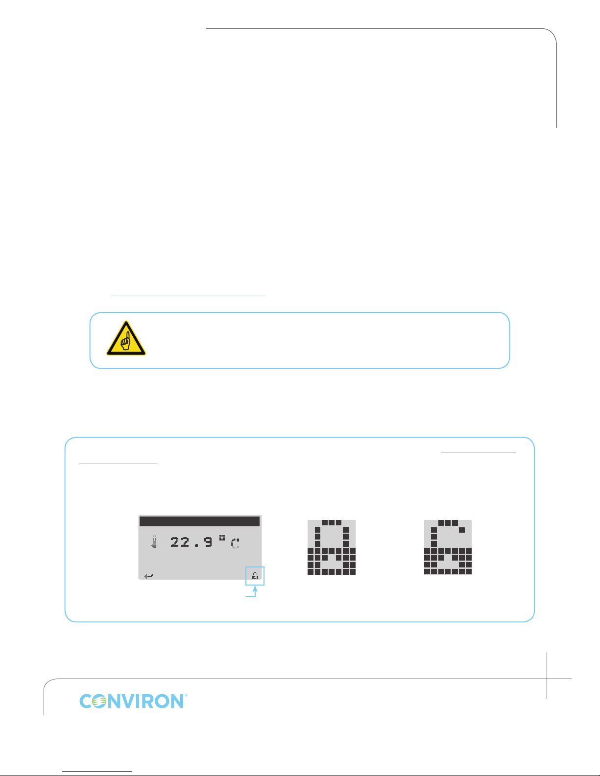
Security status is indicated by the padlock icon in the lower right of the screen. If no icon is present,
security is disabled.
TEMPERATURE STATUS
2 2 . 9
Security Stats Icon
(absent when DISABLED)
SECURITY ENABLED
User Logged OUT
SECURITY ENABLED
User Logged IN
January 2016 | 256573R04
5-1
Page 32
CHAPTER 5 | SECURITY MENU
---MAIN MENU---
< > to S elect
< > t o Continue
< > t o Continue
< > t o Continue
---SECURITY MENU---
< > to S elect
LOGIN
< > t o continue
Security is turned off
only factory access
level requires login!
< > t o Continue
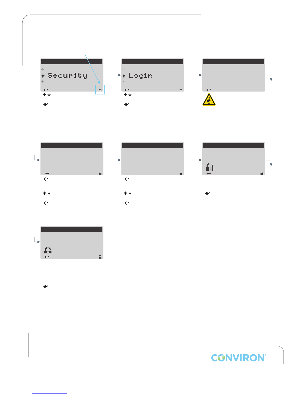
Icon Indicates
Security ENABLED
P rogram
S ecurity
A larm
< / > to select Security
< > to access Security menu
LOGIN
Select User: _ser 1
Password : 00000
> to move cursor to Select
<
User parameter
< / > to select user
< > to accept and move
cursor to Password parameter
L ogout
L ogin
P asswords
< / > to select Login
< > to access Login screen
LOGIN
Select User: User 1
Password : 12_00
> to move cursor to rst
<
digit of Password
< / > to change digit value
< > to move to next digit
Repeat until all digits are entered.
If security is DISABLED
in the Option menu, only
the Service menu requires
a user to login using the
Factory password (which
can be obtained by
calling Conviron)
LOGIN
Select User: User 1
Password : 12300
Login Failed
If Password is incorrect ‘Login
Failed’ will display
< > to continue and return to
the Security menu.
Select User: User 1
Password : 12345
If Password is correct ‘Login
Successful’ will display, and the
security icon will change to an
open padlock.
<
> to continue and return to
the Security menu
5-2
Janaury 2016 | 256573R04
LOGIN
Login Successful
Page 33
CHAPTER 5 | CMP6010 User Manual
< > to S elect
< > to S elect
< > t o continue
You are already logged
< > t o continue
< > t o continue
< > t o continue
< > t o continue
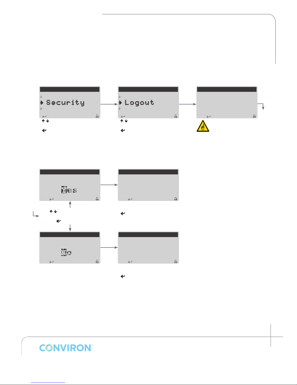
5.2 Logging Out
Users should log out immediately after completing necessary tasks at the controller to ensure that no
changes are made unintentionally to programs or chamber parameters by anyone other than the intended
user. As a safeguard, all users are automatically logged out after a period of ve minutes of inactivity.
---MAIN MENU---
P rogram
S ecurity
A larm
< / > to select Security
< > to access Security menu
Are you sure you want
to logout?
LOGOUT
< / > to select Yes or No
< > to continue
---SECURITY MENU---
P asswords
L ogout
L ogin
< / > to select Logout
< > to accept
LOGOUT
Logout successful.
Logout successful
< > to continue and return to
Security menu
LOGOUT
out!
The above screen will
display if the user is
already logged out.
Are you sure you want
to logout?
LOGOUT
LOGOUT
Logout cancelled.
Logout canceled
< > to continue and return to
Security menu
January 2016 | 256573R04
5-3
Page 34
CHAPTER 5 | SECURITY MENU
< > t o Continue
< > to S elect
< > to S elect
Enter User / Passwords
Enter User / Passwords
< > t o Continue
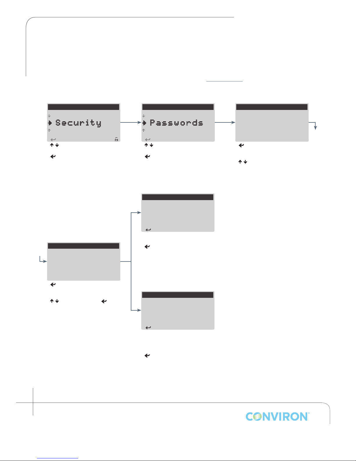
5.3 Changing a Password
To change the password for a specic User, follow the procedure below. If a password has been
forgotten, the corresponding User account must be reset using the Reset User item from the Service
menu, which requires the Factory login password (see section 9.5 Reset User).
---MAIN MENU---
P rogram
S ecurity
A larm
< / > to select Security
< > to access Security menu
CHANGE PASSWORD
Select User: User 1
Old Password: 00000
New Password: 123{0
---SECURITY MENU---
L ogin
P asswords
L ogout
< / > to select Passwords
< > to access Change
Password screen
CHANGE PASSWORD
Select User: User 1
Old Password: 00000
New Password: 12345
Password Successfully
Changed.
Password successfully changed
<
> to continue and return to
the Security menu
CHANGE PASSWORD
Select User: User 1
Old Password: 00000
New Password: 00000
< > to move cursor to User
parameter
< / > to select the user for which
the password is to be changed
< > to move cursor to ‘Old
Password’ parameter.
< / > to change value,
move to next digit.
Repeat until Old and New
passwords are entered
5-4
Janaury 2016 | 256573R04
< > to
CHANGE PASSWORD
Select User: User 1
Old Password: 00000
New Password: 12345
Incorrect Password!
Operation Cancelled.
If Old Password is entered
incorrectly, the above message
will display
<
> to continue and return to
Security screen
Select Passwords and repeat
procedure until password is
changed successfully.
Page 35
CHAPTER 6 | CMP6010 User Manual
< > to S elect
< > to S elect
< > to S elect
Set Low Limit: -05.0c
55.0c
<Esc> t o Exit
< > to S elect
to Scroll
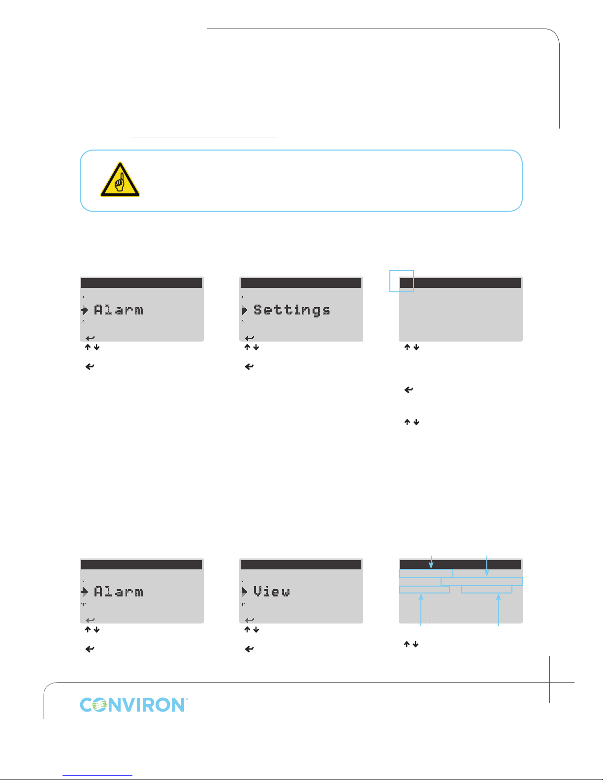
6.0 ALARM MENU
From the Alarm menu the user can view and clear the alarm history and change alarm settings for
temperature and humidity processes. For information on specic alarms and alarm troubleshooting,
see section 7.0 ALARM TROUBLESHOOTING
• If the temperature alarm limit is reached, the controller will trigger a visual and
audible alarm, and will shut the chamber OFF
• If the humidity alarm limit is reached, the controller will trigger a visual and
audible alarm however the chamber will remain ON
6.1 Changing Alarm Settings
Flashing Cursor Indicating
Screen/Menu Title Selected
---MAIN MENU---
S ecurity
A larm
S ervoce
< / > to select Alarm
< > to access Alarm menu
---ALARM MENU---
C lear
S ettings
V iew
< / > to select Settings
< > to access Settings screens
TEMPERATURE ALARM
—
Set High Limit:
< / > to toggle between
Temperature Alarm and
Humidity Alarm screens (with
cursor selecting screen title)
<
> to move cursor through
congurable parameters on
screen
<
/ > to change value of
selected parameter
<
Esc
> to exit (parameter values
are
automatically saved)
6.2 Viewing Alarm History
The View option allows the user to review the most recent 15 alarm events. Each event includes date,
time, and status (alarm limit set point—‘Lim’, and actual value—‘Act’) information. Each time the
controller is powered on, a ‘Bootup’ alarm is saved to the alarm history.
Alarm Type Time/Date
---MAIN MENU---
S ecurity
A larm
S ervoce
---ALARM MENU---
S ettings
V iew
C lear
VIEW ALARM HISTORY
01 Bootup
Act: 000 Lim: 000
02 Bootup
Act: 000 Lim: 000
< / > to select Alarm
< > to access Alarm menu
< / > to select View
< > to access View screen(s)
Actual Conditions Alarm Limit
< / > to scroll through Alarm
events
<
Esc
>
to return to Alarm menu
January 2016 | 256573R04
6-1
Page 36
CHAPTER 6 | ALARM MENU
< > to S elect
< > to S elect
A
to clear all alarms?
< > t o continue
CLEAR ALARM HISTORY
A
to clear all alarms?
< > t o continue
Alarm history cleared.
< > t o continue
< > t o continue
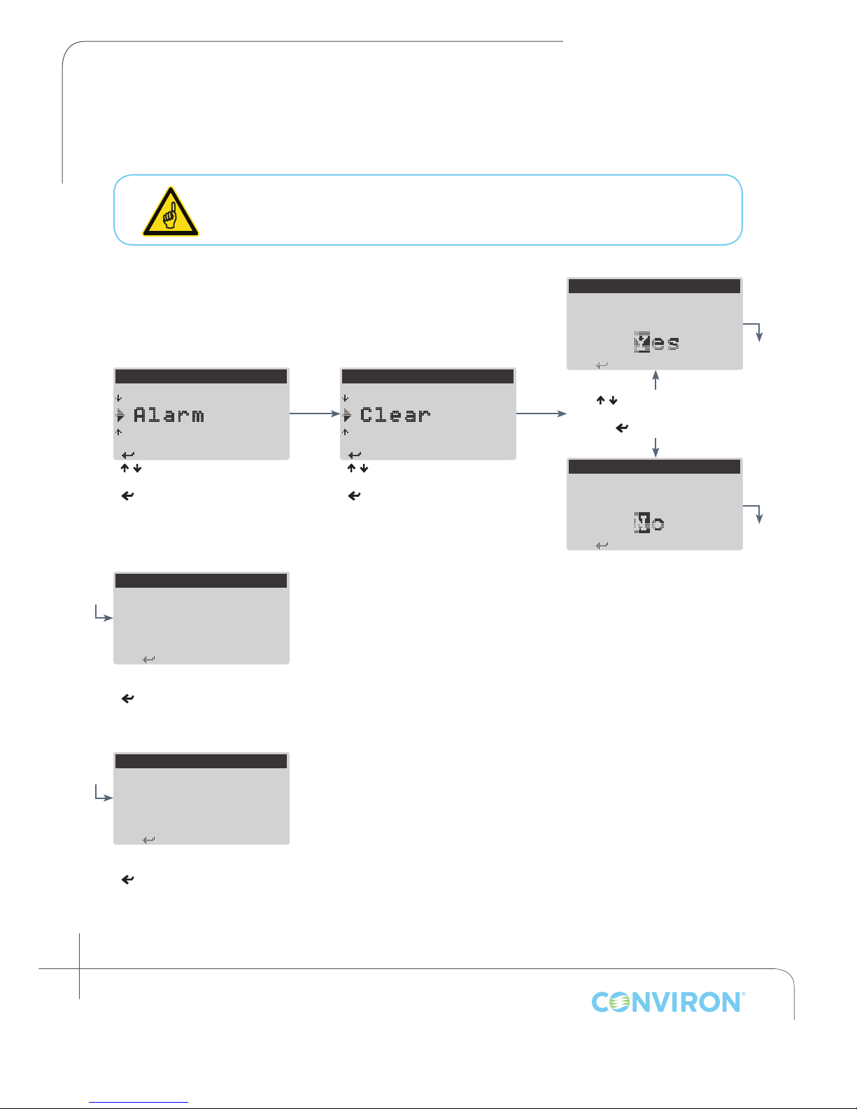
6.3 Clearing Alarm History
The Clear menu item allows the user to clear all entries from the alarm history.
Users should clear the alarm history after it has been viewed to avoid confusion
between old and new alarms.
CLEAR ALARM HISTORY
re you sure you want
a
---MAIN MENU---
S ecurity
A larm
S ervoce
< / > to select Alarm
< > to access Alarm menu
CLEAR ALARM HISTORY
a
Alarm history cleared
< > to continue and return to
Alarm menu
CLEAR ALARM HISTORY
b
Alarm history
restored.
---ALARM MENU---
V iew
C lear
S ettings
< / > to select Clear
< > to clear alarm history
< / > to select Yes or No
< > to continue
re you sure you want
b
Alarm history restored
< > to continue and return to
Alarm menu
6-2
Janaury 2016 | 256573R04
Page 37
CHAPTER 7 | CMP6010 User Manual
7.0 ALARM TROUBLESHOOTING
The CMP6010 controller is equipped with several different alarms designed to protect equipment from
damage and help ensure experimental integrity.
Controller alarms include:
• Temperature limit
• Humidity limit
• Low water level or door open
• Refrigeration low pressure: 3 different alarm conditions
• Refrigeration high pressure: 3 different alarm conditions
When temperature and refrigeration alarms are triggered, the chamber will automatically shut OFF to
protect core components from damage.
Humidity and low water alarms will trigger the appropriate alarm indicators, but the chamber will
remain ON.
7.1 Alarm State Indication
The CMP6010 Controller uses two warning devices to indicate alarm state. The Alarm button on the
keypad will illuminate red (either ashing or solid depending on alarm state), and the alarm buzzer
will sound. The table below indicates the meaning of each alarm state based on the behavior of the
warning devices.
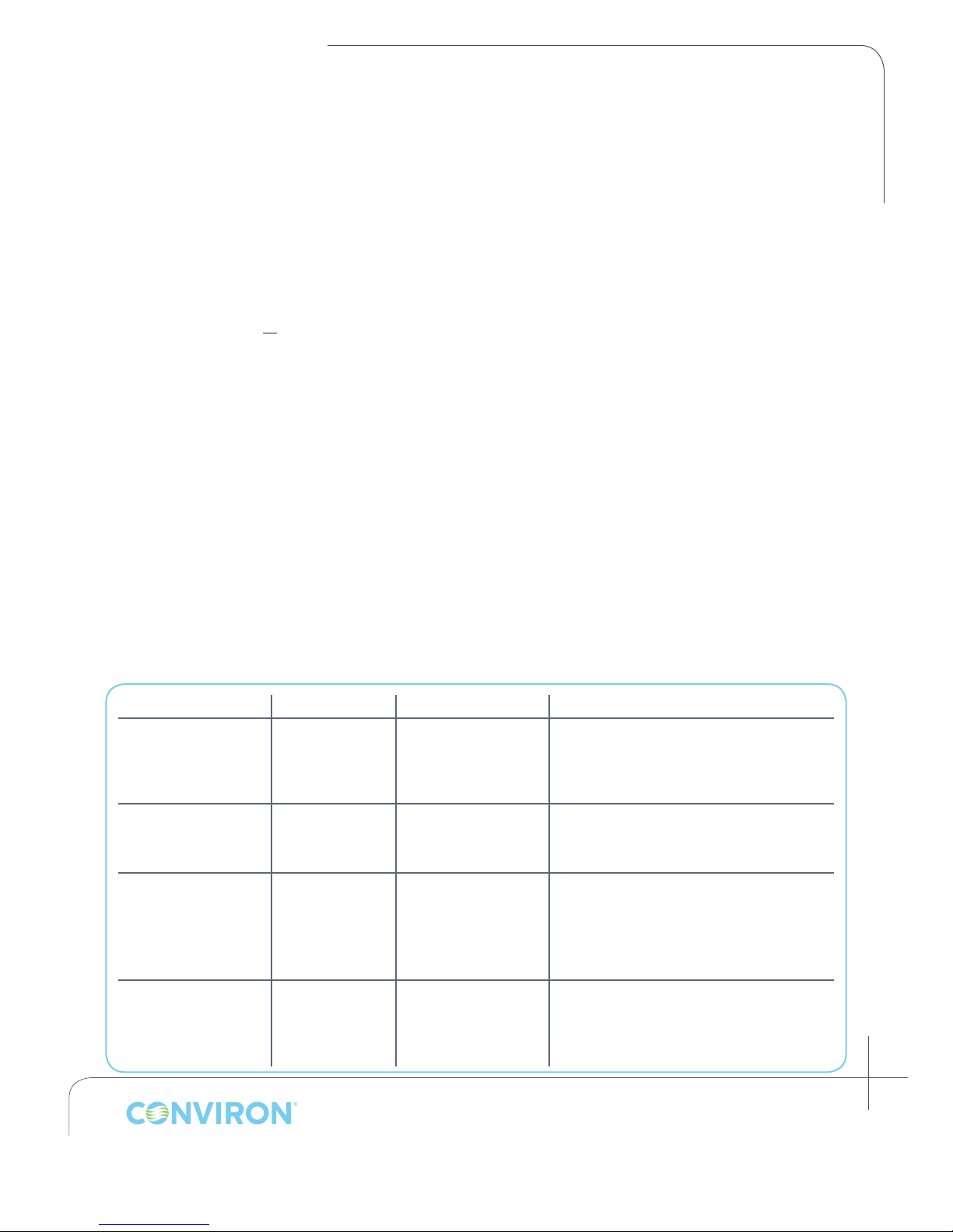
Alarm Button Alarm Buzzer Alarm State Description
An alarm condition has triggered
Flashing Red ON
Flashing Red OFF
Solid Red OFF
Active,
Unacknowledged
Active,
Acknowledged
Inactive,
Unacknowledged
an alarm, no corrective action has
been taken, and the user has not
acknowledged it.
An alarm condition has triggered an
alarm, no corrective action has been
taken, and the user has acknowledged it.
An alarm condition has triggered
an alarm and corrective action has
been taken (or the problem has
resolved itself), and the user has not
acknowledged it
OFF OFF
Inactive,
Acknowledged
An alarm condition has triggered an
alarm, corrective action has been taken,
and the user has acknowledged it.
January 2016 | 256573R04
7-1
Page 38
CHAPTER 7 | ALARM TROUBLESHOOTING
< > t o Acknowledge
7.2 Alarm Types
The CMP6010 Controller uses ve different primary alarm types with a total of 12 possible alarms
to monitor and alert the user to problems affecting chamber operations. All alarms are listed in
the following section, along with user troubleshooting suggestions that address the most common
cause(s) of each.
7.2.1 Viewing and Acknowledging an Alarm
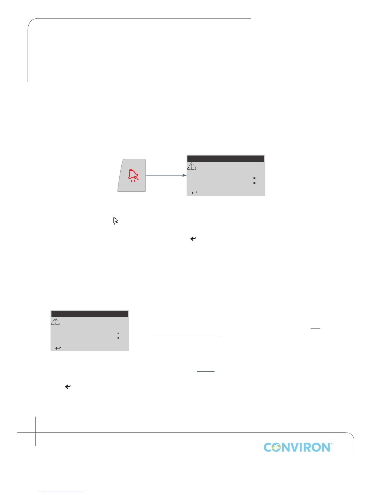
When an alarm is triggered the user must determine the alarm type in order to take action to resolve
the problem.
*TEMPERATURE ALARM*
High Limit Exceeded
Actual:
H igh Limit:
40 . 1 C
40.0 C
When Alarm button is red
(ashing or solid):
Press < > to view the alarm
information
Take note of the alarm type, and
use the alarm descriptions in
the following pages to identify
potential actions to resolve the
problem
< >
to continue and return to last
active screen before alarm button
was pressed.
7.2.2 Temperature Alarm: High Limit Exceeded (chamber: off)
*TEMPERATURE ALARM*
High Limit Exceeded
Actual:
H igh Limit:
< > t o Acknowledge
Indicates the actual temperature
within the chamber is higher than
the temperature alarm High Limit
set point.
40 . 1 C
40.0 C
User corrective action(s):
1. Check the High Temperature Alarm set point (see section 6.1
Changing Alarm Settings)
2. Remove any sources of heat that may have been placed inside
the chamber
3. Call your local representative or contact Conviron for more
information (see page i).
• < >
7-2
Janaury 2016 | 256573R04
to acknowledge alarm
Page 39
CHAPTER 7 | CMP6010 User Manual
7.2.3 Temperature Alarm: Low Limit Exceeded (chamber: off)
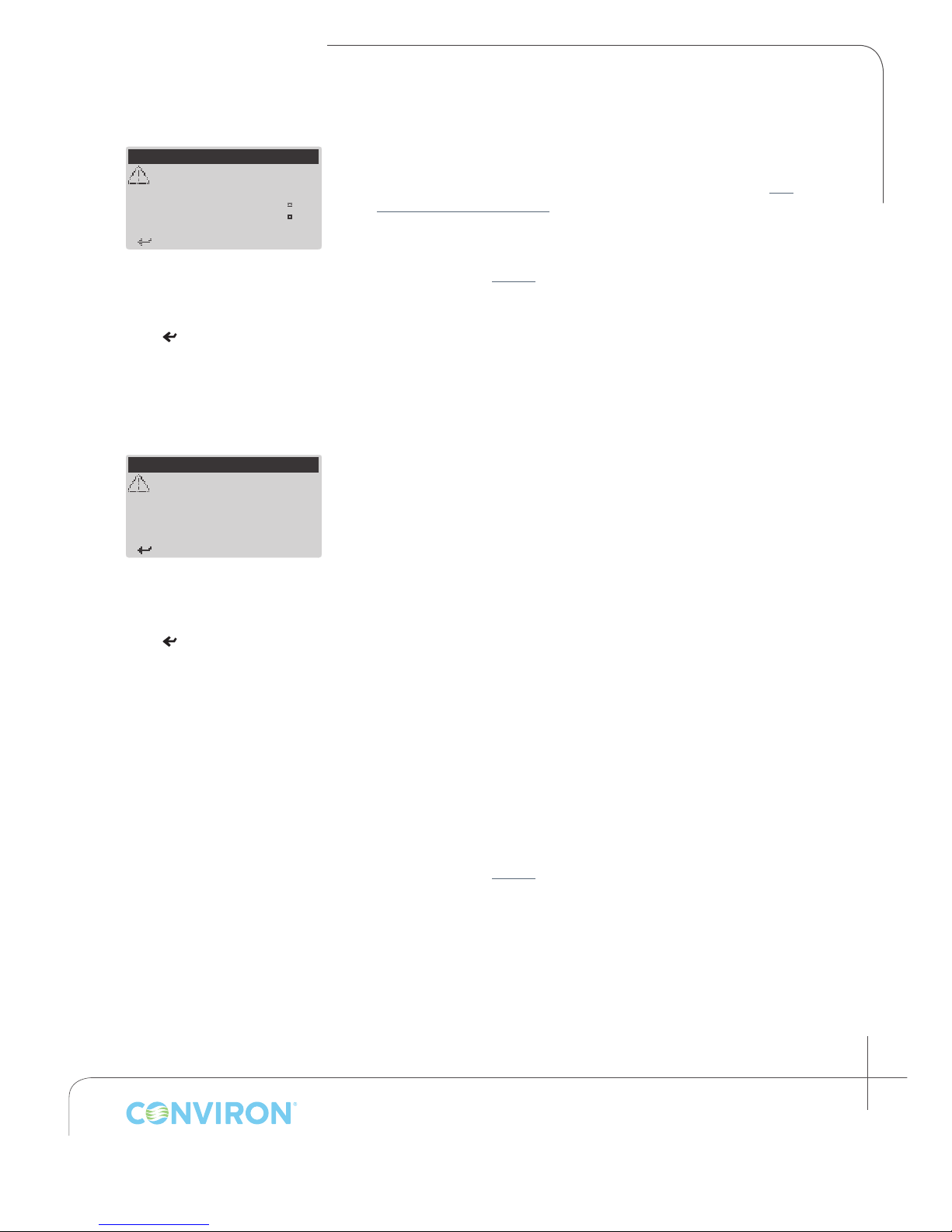
*TEMPERATURE ALARM*
Low Limit Exceeded
Actual:
L ow Limit:
< > t o Acknowledge
Indicates the actual temperature
within the chamber is lower than
the temperature alarm Low Limit
set point.
• < >
to acknowledge alarm
3.9 C
4.0 C
User corrective action(s):
1. Check the Low Temperature Alarm set point (see section 6.1
Changing Alarm Settings)
2. Ensure the door is closed properly
3. Call your local representative or contact Conviron for more
information (see page i).
7.2.4 Humidity Alarm: High Limit Exceeded (chamber: on)
***HUMIDITY ALARM***
High Limit Exceeded
Actual: 091 %RH
High Limit: 090 %RH
< > t o Acknowledge
Indicates the actual relative
humidity within the chamber is
higher than the humidity alarm
High Limit set point.
• < >
to acknowledge alarm
User corrective action(s):
1. Inspect the inside of the chamber for signs of water. If there is
water present, stop the chamber immediately and shut the water
supply off
2. If the relative humidity set point is high (more than 90%), water
droplets may occasionally form on the humidity sensor resulting
in an inaccurate reading of 100%. Open the door until the
display reading drops below the Humidity Alarm High Limit set
point value
3. If relative humidity is not critical for the experiment, keep the
door open for less than 1 minute or until the actual relative
humidity reading is lower than the relative humidity set point
4. Verify the relative humidity set point is lower than 90% AT ALL TIMES
5. The Humidity Alarm High Limit must be higher than the relative
humidity set point at anytime throughout the programs that
comprise the Schedule or it will unintentionally trigger an alarm
6. Remove any sources of humidity that may have been placed
inside the chamber
7. Call your local representative or contact Conviron for more
information (see page i).
January 2016 | 256573R04
7-3
Page 40
CHAPTER 7 | ALARM TROUBLESHOOTING
< > t o Acknowledge
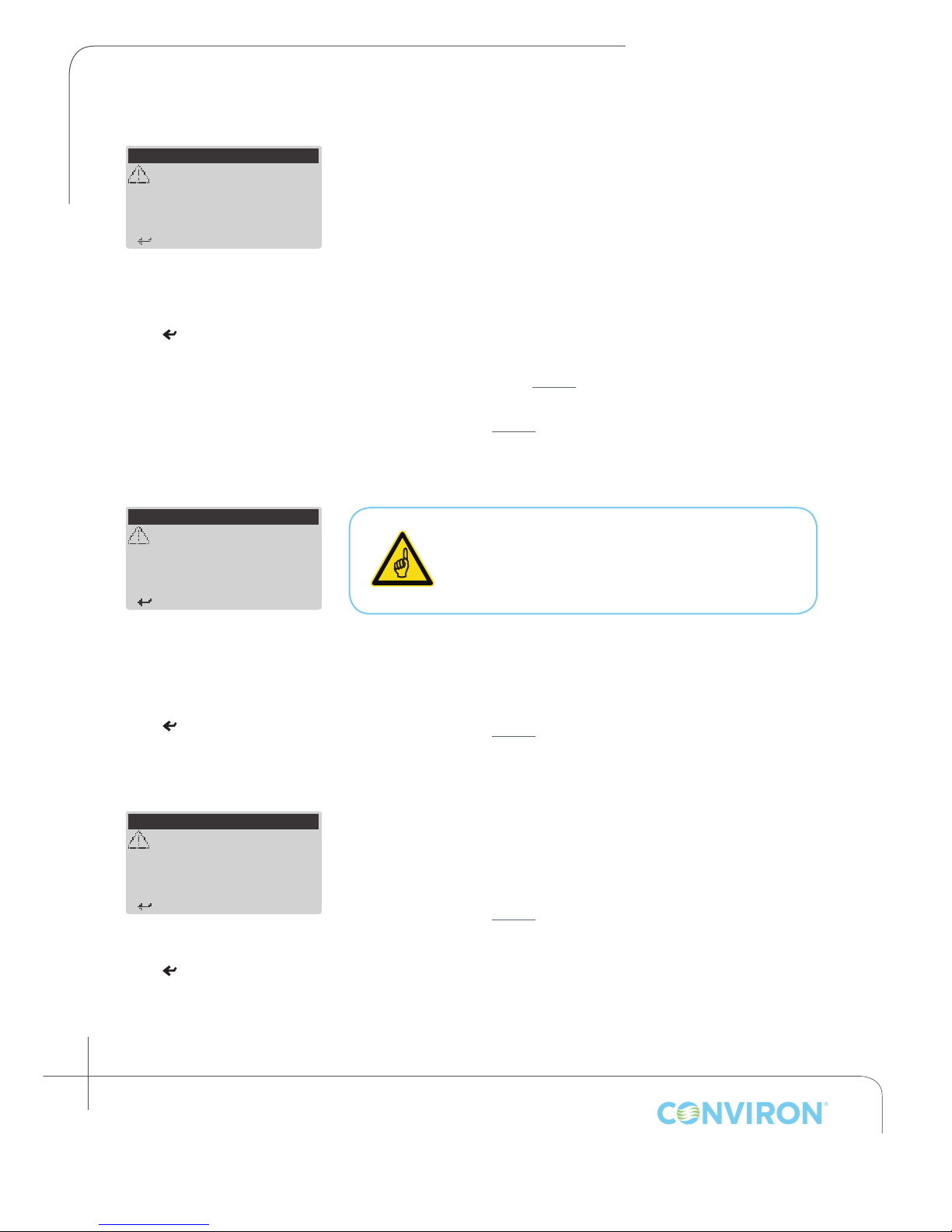
***WATER ALARM***
7.2.5 Humidity Alarm: Low Limit Exceeded (chamber: on)
***HUMIDITY ALARM***
Low Limit Exceeded
Actual: 029 %RH
Low Limit: 030 %RH
Indicates the actual relative
humidity within the chamber is
lower than the humidity alarm Low
Limit set point.
User corrective action(s):
1. Verify the water supply and strainer (if equipped) are functioning
properly
2. Verify the chamber door is closed properly
3. Verify that the exhaust/fresh air regulator is functioning properly
4. The Humidity Alarm ‘Low Limit’ must be lower than any relative
humidity set point at any time throughout the programs that
comprise the Schedule
• < >
to acknowledge alarm
5. If the Humidity Alarm ‘Low Limit’ is set to 0 and the alarm
persists, the sensor must be replaced. Contact Conviron for
more information (see page i)
6. Call your local representative or contact Conviron for more
information (see page i).
7.2.6 Low Water Level (chamber: on, humidication system: off)
Low Level
Water level low for
60 seconds with
additive RH setpoint!
< > t o Acknowledge
Indicates the liquid level switch
in the ultrasonic humidier has
detected a low water level for 60
seconds, during a time when an
additive humidity set point has
been programmed.
• < >
to acknowledge alarm
User corrective action(s):
1. Verify the water supply and strainer (if equipped) are functioning
properly
2. Call your local representative or contact Conviron for more
information (see page i).
The Low Water Level warning will stop the
Humidier to protect the ultrasonic transducers
from damage. To restart humidication, stop and
restart the Schedule once the problem is resolved.
7.2.7 Door Open (chamber: on, humidication system: off)
***DOOR ALARM***
Door open for
60 seconds with
chamber running!
< > t o Acknowledge
Indicates the chamber door has
been open for 60 seconds.
• < >
7-4
Janaury 2016 | 256573R04
to acknowledge alarm
User corrective action(s):
1. Ensure no obstructions prevent the chamber door from closing
completely
2. Call your local representative or contact Conviron for more
information (see page i).
Page 41
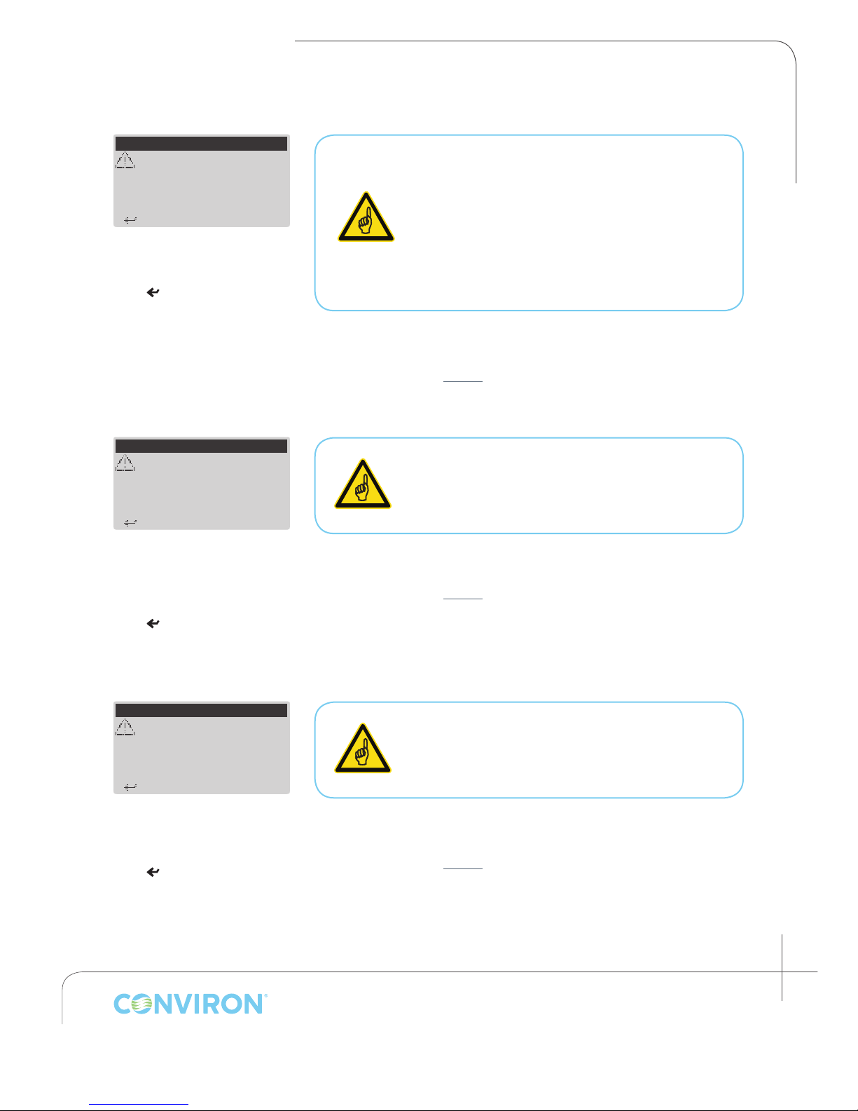
< > t o Acknowledge
< > t o Acknowledge
7.2.8 High Pressure Alarm: Warning (chamber: on)
**PRESSURE ALARM**
High Pressure
High pressure cut-out
warning!
Indicates the refrigerant pressure
has exceeded the factory set high
pressure cut-out limit.
• < >
to acknowledge alarm
User corrective action(s):
1. Call your local representative or contact Conviron for more
information (see page i).
If this Alarm occurs only once, or very infrequently,
it is an indication that the refrigeration system
experienced a temporary condition which triggered
the high pressure cut-off set point, but recovered
automatically and does not require service.
If this Alarm occurs frequently, it may be an indication
that the refrigeration system requires service.
7.2.9 High Pressure Alarm: Repeat (chamber: off)
CHAPTER 7 | CMP6010 User Manual
**PRESSURE ALARM**
High Pressure
High pressure cut-out
3 times in 30 minutes!
Chamber shut down.
Indicates the refrigerant pressure
has exceeded the factory set
high pressure cut-out limit and
recovered 3 times in a 30 minute
timespan.
• < >
to acknowledge alarm
User corrective action(s):
1. Call your local representative or contact Conviron for more
information (see page i).
This Alarm is an indication of a potential failure in
the refrigeration system. To protect components of
the refrigeration system, the chamber automatically
shuts off
7.2.10 High Pressure Alarm: Time (chamber: off)
**PRESSURE ALARM**
High Pressure
High pressure cut-out
for 45 seconds!
Chamber shut down.
< > t o Acknowledge
Indicates the refrigerant pressure
has exceeded the factory set high
pressure cut-out limit for a duration
of 45 seconds.
• < >
to acknowledge alarm
User corrective action(s):
1. Call your local representative or contact Conviron for more
information (see page i).
This Alarm is an indication of a potential failure in
the refrigeration system. To protect components of
the refrigeration system, the chamber automatically
shuts off
January 2016 | 256573R04
7-5
Page 42
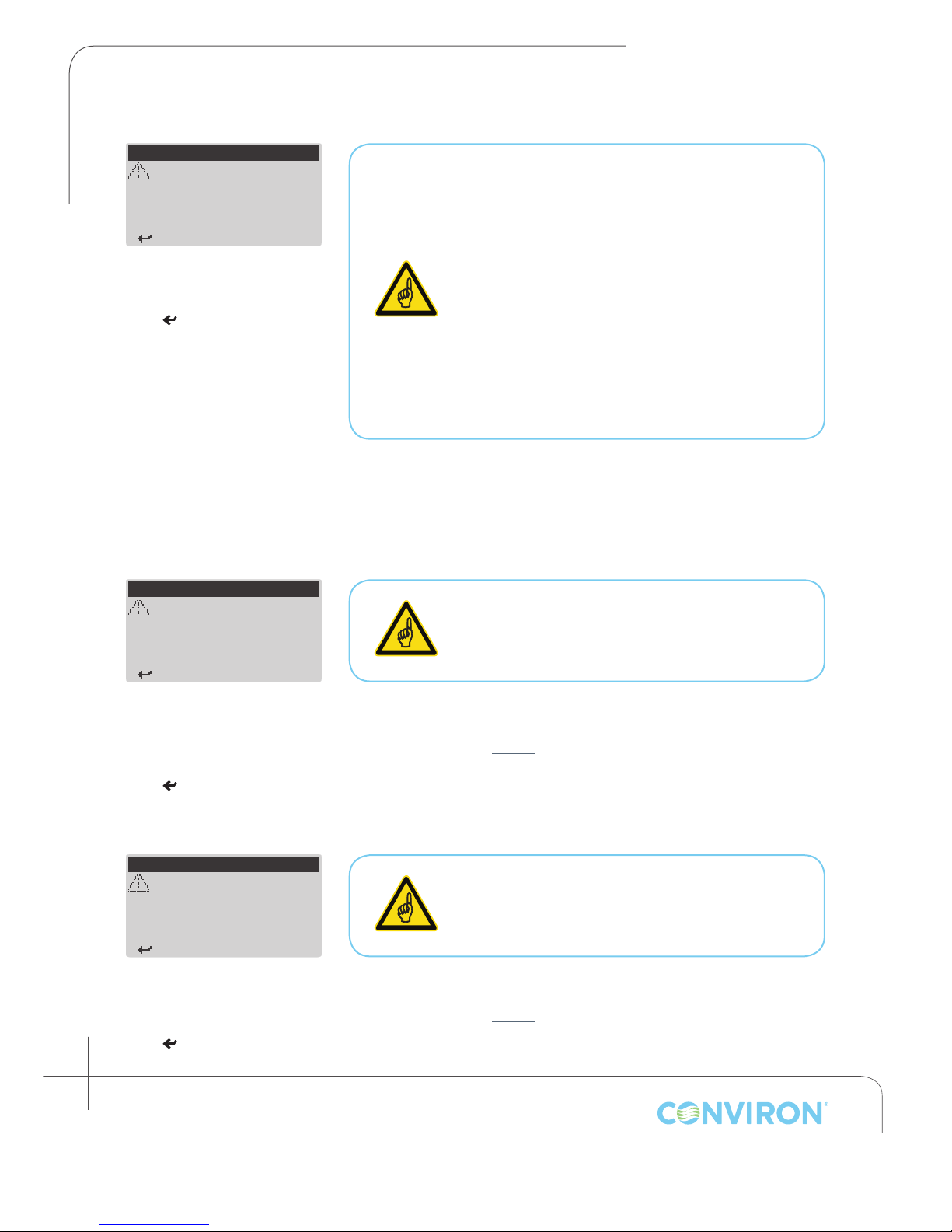
CHAPTER 7 | ALARM TROUBLESHOOTING
< > t o Acknowledge
7.2.11 Low Pressure Alarm: Warning (chamber: on)
**PRESSURE ALARM**
Low Pressure
Low pressure cut-out
warning!
< > t o Acknowledge
Indicates the refrigerant pressure
has exceeded the factory set low
pressure cut-out limit.
• < >
to acknowledge alarm
If this Alarm occurs only once, or very infrequently,
it is an indication that the refrigeration system
experienced a temporary condition which
triggered the high pressure cut-off set point, but
recovered automatically and does not require
service.
This may also occur after the doors have been
open for a long period. NEVER KEEP THE DOOR
OPEN FOR LONGER THAN three MINUTES
WHILE THE CHAMBER IS RUNNING. If more than
three minutes are required, stop the Schedule
If this Alarm occurs frequently, it may be an
indication that the refrigeration system may
require service.
User corrective action(s):
Call your local representative or contact Conviron for more
information (see page i).
7.2.12 Low Pressure Alarm: Repeat (chamber: off)
**PRESSURE ALARM**
Low Pressure
Low pressure cut-out
3 times in 30 minutes!
Chamber shut down.
This Alarm is an indication of a potential failure in
the refrigeration system. To protect components
of the refrigeration system, the chamber
automatically shuts off
Indicates the refrigerant pressure
has exceeded the factory set
low pressure cut-out limit and
recovered 3 times in a 30 minute
timespan.
• < >
7.2.13 Low Pressure Alarm: Time (chamber: off)
**PRESSURE ALARM**
Low pressure cut-out
for 45 seconds!
Chamber shut down.
< > t o Acknowledge
Indicates the refrigerant pressure
has exceeded the factory set low
pressure cut-out limit for a duration
of 45 seconds.
• < >
7-6
Janaury 2016 | 256573R04
to acknowledge alarm
Low Pressure
to acknowledge alarm
User corrective action(s):
1. Call your local representative or contact Conviron for more
information (see page i).
This Alarm is an indication of a potential failure in
the refrigeration system. To protect components
of the refrigeration system, the chamber
automatically shuts off
User corrective action(s):
1. Call your local representative or contact Conviron for more
information (see page i).
Page 43
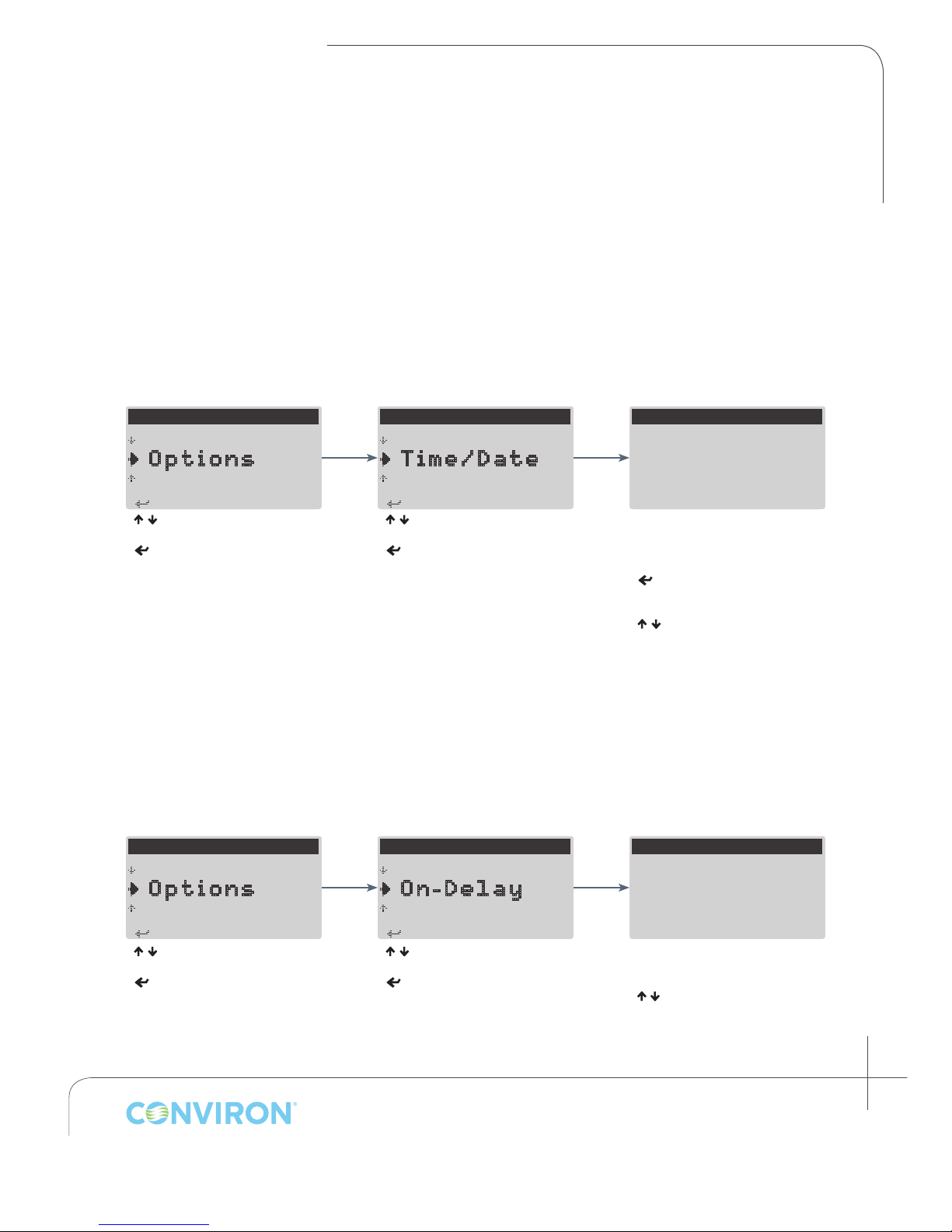
CHAPTER 8 | CMP6010 User Manual
< > to S elect
< > to S elect
< > to S elect
<Esc> to exit
< > to S elect
8.0 OPTIONS MENU
The Options menu contains items that allow the user to congure time and date, on-delay, enable/
disable security, set up network communications, and designate light range and temperature/
humidity offsets (if required).
8.1 Setting Time/Date
To ensure experimental integrity it is important for the time and date to be set before running the
schedule. Time and date can be adjusted after the schedule has begun, but it will affect the duration
of the currently running program timeline, and is not recommended.
---MAIN MENU---
S ervice
O ptions
S tatus
< / > to select Options
< > to accept
---OPTIONS MENU---
S etup
T ime/Date
O n-delay
< / > to select Time/Date
< > to accept
SET CLOCK
T ime:
D ate:
There are ve parameters to
adjust: Hours, Minutes, Day,
Month, and Year.
> to scroll through
<
parameters
< / > to adjust parameter
<
Esc
> to exit and return to the
Options menu
04:56
01-JAN-2013
8.2 Setting On-Delay
The controller has the ability to delay start-up of the chamber after a power failure to reduce electrical
demand when multiple chambers are utilizing the same power supply. The delay can be set from
0-900 seconds, accommodating installations where large numbers of growth chambers are used.
---MAIN MENU---
S ervice
O ptions
S tatus
---OPTIONS MENU---
T ime/Date
O n-Delay
S ecurity
ON DELAY
S elect unit on-delay
after power outage:
_00 Seconds
< / > to select Options
< > to access the Options
menu
< / > to select On-Delay
< > to access the On-Delay
screen
Cursor will default to Seconds
parameter
< / > to select On-Delay in seconds
<
Esc
> to exit and return to the
Options menu.
January 2016 | 256573R04
8-1
Page 44
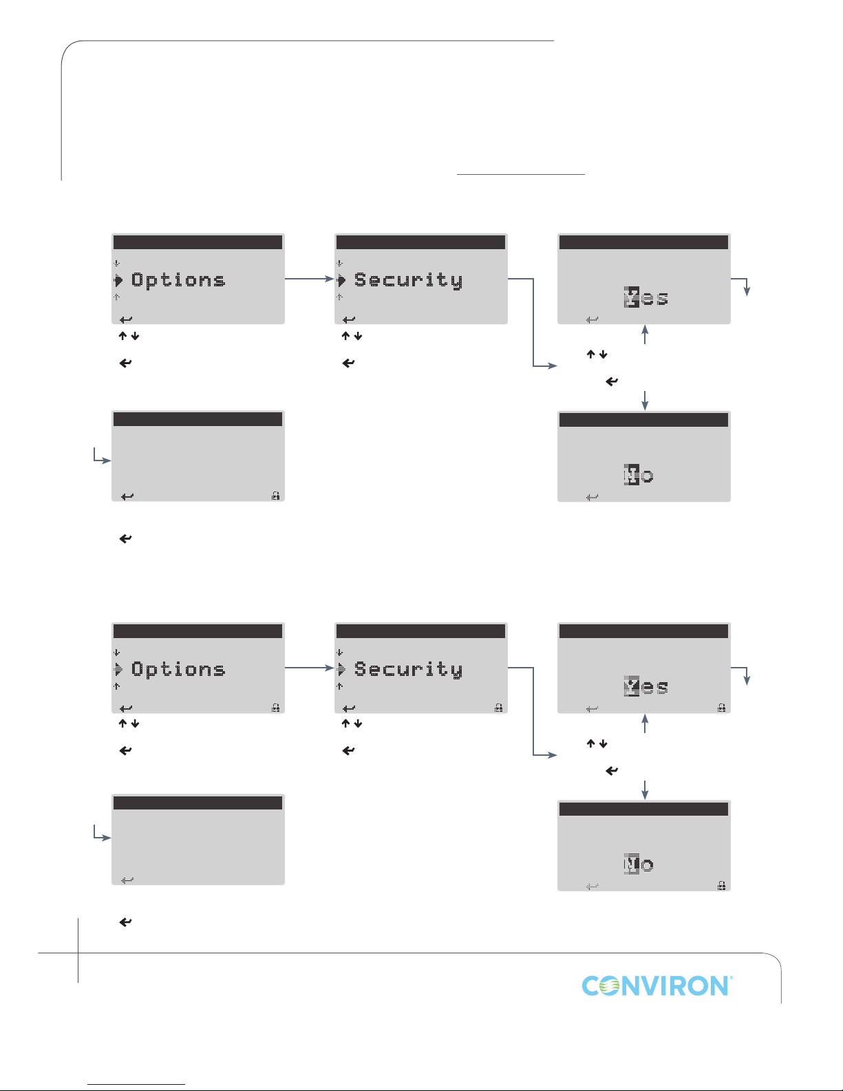
CHAPTER 8 | OPTIONS MENU
< > to S elect
< > to S elect
A
< > t o continue
A
< > t o continue
< > t o continue
< > to S elect
< > to S elect
< > t o continue
< > t o continue
turned off. Only
< > t o continue
8.3 Enabling and Disabling Security
The Security item from the Options menu allows the user to enable or disable User level security (for
more information on using Security features, see section 5.0 SECURITY MENU).
8.3.1 Enabling Security
---MAIN MENU---
S ervice
O ptions
S tatus
< / > to select Options
< > to access the Options
menu
SECURITY ON/OFF
Security has been
turned on. User
operations will now
require user login.
Security has been enabled
< > to continue and return to
Options menu
8.3.2 Disabling Security
---MAIN MENU---
S ervice
O ptions
S tatus
---OPTIONS MENU---
O n-delay
S ecurity
N etwork
< / > to select Security
< > to access the Security
ON/OFF screen
---OPTIONS MENU---
O n-delay
S ecurity
N etwork
CLEAR ALARM HISTORY
re you sure you want
to turn security ON ?
< / > to select Yes or No
< > to continue
CLEAR ALARM HISTORY
re you sure you want
to turn security ON ?
CLEAR ALARM HISTORY
Are you sure you want
to turn security OFF ?
< / > to select Options
< > to access the Options
menu
SECURITY ON/OFF
Security has been
factory operations
will require login.
Security has been disabled
< > to continue and return
to Options menu
8-2
Janaury 2016 | 256573R04
< / > to select Security
< > to access the Security
ON/OFF screen
< / > to select Yes or No
< > to continue
CLEAR ALARM HISTORY
Are you sure you want
to turn security OFF ?
Page 45
CHAPTER 8 | CMP6010 User Manual
< > to S elect
< > to S elect
< > / < > t o scroll
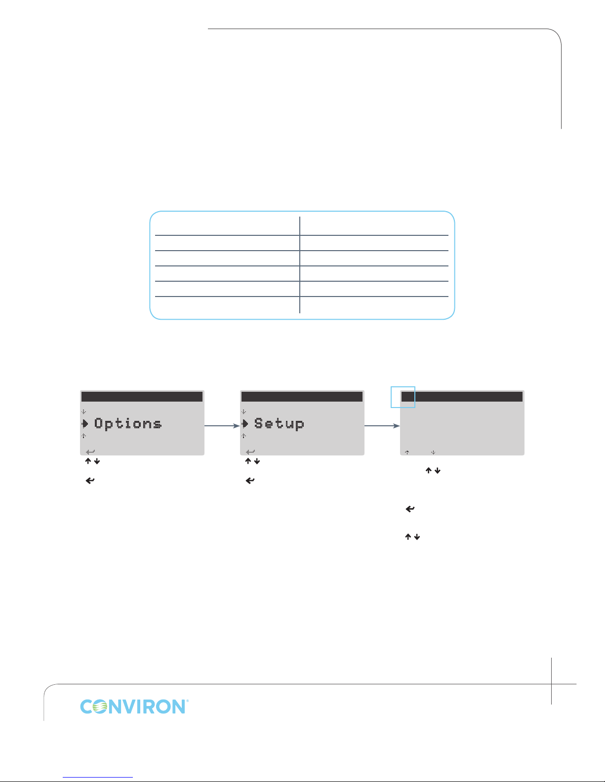
8.4 Setting Light Level and Input Offset
8.4.1 Setting Number of Discrete Light Levels
The number of discrete light levels available differs depending on chamber model and kit
conguration. Use the table below to input the correct values for the chamber kit/model.
Model Maximum Light Level
A1000PG 3
A1000AR 3
A1000TC 1
A1000IN 1
G1000 1
---MAIN MENU---
S ervice
O ptions
S tatus
< / > to select Options
< > to access the Options
menu
---OPTIONS MENU---
N etwork
S etup
T ime/Date
< / > to select Setup
< > to access the Setup
screens
Flashing Cursor Indicating
Screen/Menu Title Selected
SETUP - LIGHT LEVELS
—
Lighting Range:
0 - 3
With cursor selecting screen title,
press < / > to scroll between
Light Level setup and Input Offset
screens
< > to move cursor to Lighting
Range parameter
< / > to input maximum light
level
<Esc> to exit and return to
Options menu
January 2016 | 256573R04
8-3
Page 46
CHAPTER 8 | OPTIONS MENU
---MAIN MENU---
< > to S elect
---OPTIONS MENU---
< > to S elect
SETUP - LIGHT LEVELS
< > / < > t o scroll
C
<Esc> t o Exit
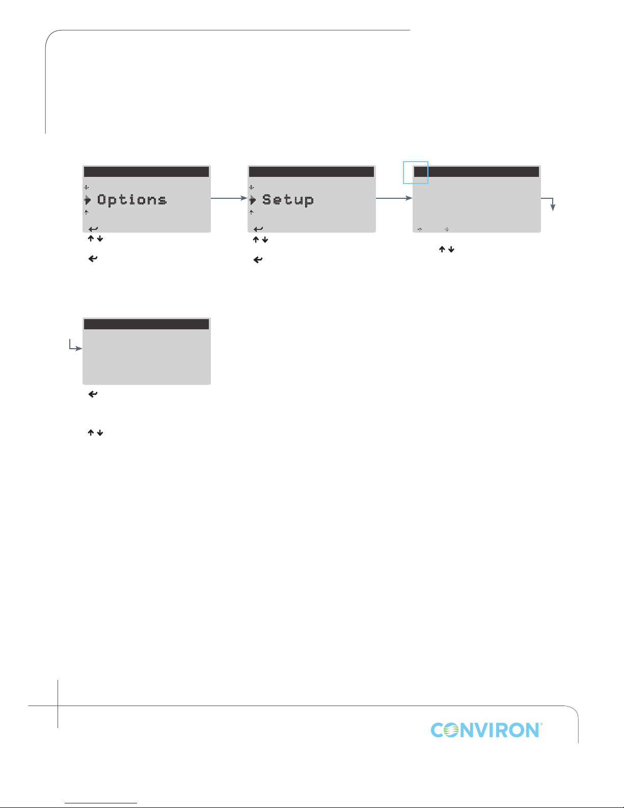
8.4.2 Setting Input Offset
The temperature and humidity sensor input to the controller can be offset if necessary to allow
calibration of the chamber sensor and display with a third party measuring device.
Flashing Cursor Indicating
Screen/Menu Title Selected
—
S ervice
O ptions
S tatus
N etwork
S etup
T ime/Date
Lighting Range:
0 - 3
< / > to select Options
< > to access the Options
menu
SETUP - INPUT OFFSET
TEMP Offset:
HUM Offset:
CO2 Offset:
< > to scroll cursor through
TEMP and HUM Offset
parameters
< / > to change values
<Esc> to exit and return to
Options menu
00.0
00 %RH
0000
ppm
õ
Optional
< / > to select Setup
< > to access the Setup
screens
With cursor selecting screen title,
press <
Light Level setup and Input Offset
screens
/ > to scroll between
8-4
Janaury 2016 | 256573R04
Page 47
CHAPTER 8 | CMP6010 User Manual
< > to S elect
< > to S elect
Controller IP Address:
<Esc> t o Save & Exit
C
H
Controller IP Address:
<Esc> t o Save & Exit
C
H
< > t o continue
< > t o continue
< > t o continue
< > t o continue
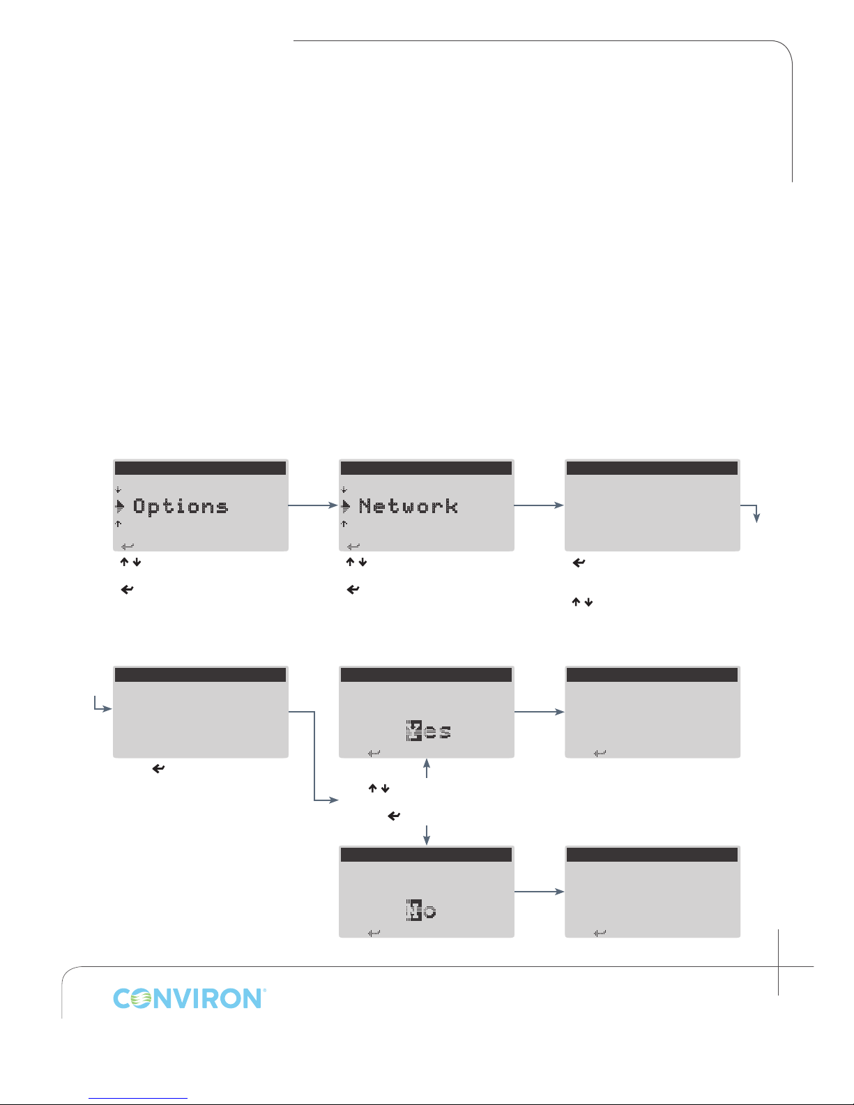
8.5 Conguring Network Communication
Network settings are input and edited at the Communication Settings screen. Network
communications allow the controller to be connected to a local area network or single computer for
downloading of logged experimental data via le transfer protocol (FTP). The controller can also
be connected to an optional Conviron Central Management™ network, which provides additional
functionality such as downloading experimental data, trend graphs, and alarm notications. For more
information on Central Management, contact Conviron.
The controller can be connected in one of two ways:
• A single computer directly to the controller. This requires a cross-over Ethernet cable connected
to the chamber (or controller) Ethernet port (located at the rear of Adaptis and G1000 chambers).
• Controller connected to network on which computer resides. This requires a straight-through
Ethernet cable connected to the chamber (or controller) Ethernet port.
8.5.1 Inputting Network Communication Settings
---MAIN MENU---
S ervice
O ptions
S tatus
< / > to select Options
< > to accept
COMMUNICATION SETTINGS
192.168.000.010
ontroller Netmask:
255.255.255.000
ost, IP Address:
192.168.000.100
Press < > once the last
parameter has been edited.
<Esc> to continue to save
prompt
---OPTIONS MENU---
S ecurity
N etwork
S etup
< / > to select Network
< > to accept
COMMUNICATION SETTINGS
Save changes to
network settings?
< / > to select Yes or No
< > to continue
COMMUNICATION SETTINGS
Save changes to
network settings?
COMMUNICATION SETTINGS
000.000.000.000
ontroller Netmask:
000.000.000.000
ost, not present
< > navigate through
congurable parameters
< / > to change value of selected
parameter
COMMUNICATION SETTINGS
Changes saved.
COMMUNICATION SETTINGS
Changes discarded.
January 2016 | 256573R04
8-5
Page 48

CHAPTER 8 | OPTIONS MENU
8.5.2 Connecting the Controller to a Network (LAN)
1. Ensure that the controller is physically connected to the network on which the computer to be
used for downloading data resides. This requires a straight-through Ethernet cable.
2. Navigate to the controller Communication Settings screen via the Options > Network menu. See
section 8.5.1 Inputting Network Communication Settings for instructions on inputting network settings.
3. Input the network subnet mask under the ‘Controller Netmask’ heading
4. Choose an unused IP address from the same network on which the computer resides, and input
under the ‘Controller IP Address’ heading. Determining a suitable IP address may require
assistance from a network administrator or Information Services professional
5. Using an FTP client or internet browser enter the following address:
ftp://httpadmin:[email protected]
Where:
httpadmin = User name
fhttpadmin = Password
aaa.bbb.ccc.ddd = IP address chosen for the controller in Step 7
6. Once connected, the browser or FTP client will display a list of les. Files containing
experimental log data will appear in the format:
aaa.bbb.ccc.ddd YYYY-MM-DD.log
Where aaa.bbb.ccc.ddd is the IP address of the controller, and YYYY-MM-DD is the date of the
log le. Download or copy any required log les.
7. Values in the log le are comma-separated. Log les can be opened with Microsoft Excel or any
other application capable of managing comma separated values.
8-6
Janaury 2016 | 256573R04
Page 49

CHAPTER 8 | CMP6010 User Manual
8.5.3 Connecting the Controller to a Single Computer
1. Ensure that the controller is physically connected to the computer to be used for downloading
data. This requires a cross-over Ethernet cable.
2. Navigate to the controller Communication Settings screen via the Options > Network menu. See
section 8.5.1 Inputting Network Communication Settings for instructions on inputting network settings.
3. Input the network subnet mask under the ‘Controller Netmask’ heading
4. Choose an unused IP address from the same network on which the computer resides, and input
under the ‘Controller IP Address’ heading. Determining a suitable IP address may require
assistance from a network administrator or Information Services professional
5. Using an FTP client or internet browser enter the following address:
ftp://httpadmin:[email protected]
Where:
httpadmin = User name
fhttpadmin = Password
aaa.bbb.ccc.ddd = IP address chosen for the controller in Step 7
6. Once connected, the browser or FTP client will display a list of les. Files containing
experimental log data will appear in the format:
aaa.bbb.ccc.ddd YYYY-MM-DD.log
Where aaa.bbb.ccc.ddd is the IP address of the controller, and YYYY-MM-DD is the date of the
log le. Download or copy any required log les.
7. Values in the log le are comma separated. Log les can be opened with Microsoft Excel or any
other application capable of managing data organized into comma separated values.
January 2016 | 256573R04
8-7
Page 50

Page 51
CHAPTER 1 | CMP6010 User Manual
< > to S elect
<Esc> to Exit
45 %RH
< > to S elect
9.0 SERVICE MENU
This section refers to features of the controller that are available only to
personnel who possess skills and knowledge required to service the chamber.
Access to this menu and all sub-menus requires Factory level login. Call
Conviron if the Factory password is required.
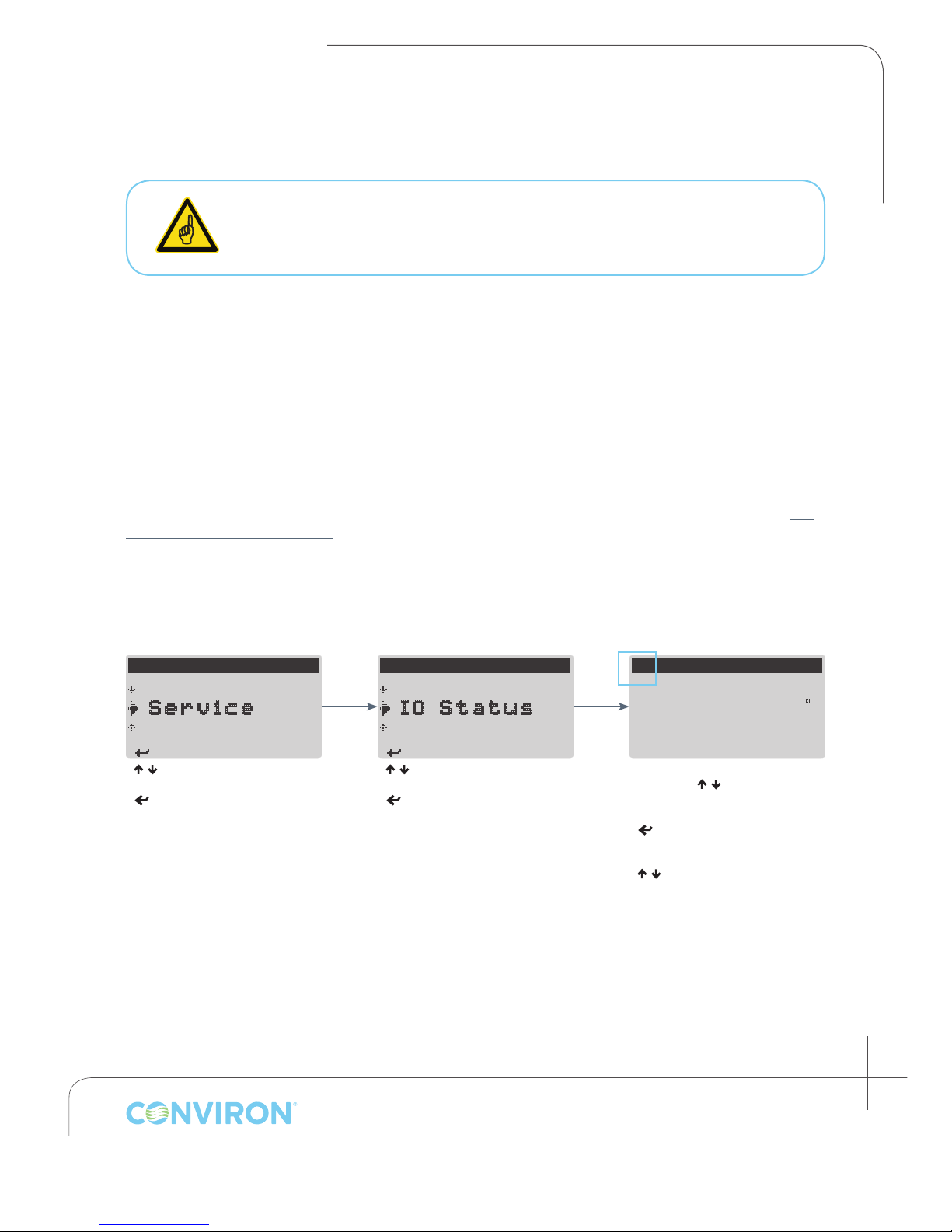
The Service menu provides technicians and other authorized personnel access to fundamental
chamber settings and diagnostic tools required for troubleshooting and service. To access this menu,
enter the Factory login password at the Security > Login screen.
9.1 I/O Status
The I/O (input/output) Status screens provide real time feedback on the state of both analog and
digital inputs and outputs at the controller. Digital and analog outputs can be manually triggered
and adjusted for servicing purposes. The Schedule must be stopped before the I/O Status screens
can be accessed. For further information on alarms types mentioned in this section, see Section 7.0
ALARM TROUBLESHOOTING.
9.1.1 Accessing and Manipulating I/O Status Screens
---MAIN MENU---
A larm
S ervice
O ptions
< / > to select Service
< > to access the Service
menu
---SERVICE MENU---
R eset User
I O Status
S ystem
< / > to select IO Status
< > to access the IO Status
screens
Flashing Cursor Indicating
Screen/Menu Title Selected
I/O STATUS
—
Analog Inputs:
Temperature:
Humidity:
With the cursor selecting screen
title, press < / > to move
between screens
< > to move between
congurable parameters
< / > to change value of selected
parameter.
23.0 C
0
January 2016 | 256573R04
9-1
Page 52

CHAPTER 1 | SERVICE MENU
9.1.2 Controller Analog Inputs
Temperature
• 24.0 °C
Displays the current chamber temperature in °C.
Humidity
• 045 %RH
Displays the current chamber humidity in percentage relative
humidity (%RH)
CO2
• 750 PPM
9.1.3 Controller Analog Outputs
Displays the current chamber carbon dioxide in parts per
million (PPM)
SUDLY
• 00.0 VDC = NOT energized
• 05.0 VDC = energized
Main power contacter. Indicates the main contacter is either
energized/not energized.
Controller Terminal:
Controller Terminal: B4
Controller Terminal: B3
Controller Terminal: B2
(if valve type = STEPPER): Y3
(if valve type = SOLENOID): Y2
ALARM
• 00.0 VDC = buzzer OFF
• 10.0 VDC = buzzer ON
HMVLV
• 00.0 VDC = fully CLOSED
• 10.0 VDC = fully OPEN
9-2
Janaury 2016 | 256573R04
Controller Terminal: Y1
Analog output for alarm buzzer. Functions as on/off device.
Controller Terminal: (if valve type = STEPPER): Y2
An analog output controlling the position of the stepper valve
when ‘stepper’ is selected as heat control type from the Service
> Cong > Temp screen. Functions across a 0-10 VDC range.
Page 53
9.1.4 Controller Digital Inputs
CHAPTER 1 | CMP6010 User Manual
DI-COASW
= CLOSED. Normal
Operation
= OPEN. Indicating alarm
condition
DI-LEVELSW
= CLOSED. Water level
nominal
= OPEN. Indicating low
water level
DI-DOORSW
= CLOSED. Indicates
chamber door closed.
= OPEN. Indicates chamber
door open.
Controller Terminal: ID1
Chamber Off Alarm. Generated when the Schedule is
running and the chamber should be running but is not for a
period of 60 seconds.
Controller Terminal: (if Float Switch Alarm = ENABLED): ID2
Low Water Level switch. Active when Float Switch Alarm
is set to enabled in the Service > Cong > Alarms screen.
Input is monitored while the Schedule is running and
humidity set point is greater than zero. Generates an alarm
when oat switch in ultrasonic humidier indicates low
water level for 60 seconds.
Controller Terminal: (if Door Open Alarm = ENABLED): ID2
Door Open switch. Active when Door Open Alarm is
enabled in Service > Cong > Alarms screen. Alarm is
generated when the chamber door is open for 60 seconds.
DI-HI-PRES
= CLOSED. Head pressure
at or above high pressure
limit. Alarm triggered
= OPEN. Head pressure
within acceptable range.
DI-LO-PRES
= CLOSED. Suction pressure
at or above high pressure
limit. Alarm triggered
= OPEN. Suction pressure
within acceptable range.
Controller Terminal: ID4
Refrigeration High (head) Pressure monitoring input.
Actively monitors head pressure while the Schedule is
running. Generates High Pressure Warning alarm each time
contact closes. Generates High Pressure Shutdown alarm
if contact remains closed for 45 seconds and/or contact
closes 3 times in a span of 30 minutes.
Controller Terminal: ID3
Refrigeration Low (suction) Pressure monitoring input.
Actively monitors suction pressure while the Schedule is
running. Generates Low Pressure Warning alarm each time
contact closes. Generates Low Pressure Shutdown alarm
if contact remains closed for 45 seconds and/or contact
closes 3 times in a span of 30 minutes.
January 2016 | 256573R04
9-3
Page 54
CHAPTER 1 | SERVICE MENU
9.1.5 Controller Digital Outputs
RSVLV
= CLOSED. Solenoid valve
open and lling.
= OPEN. Solenoid valve
closed.
CFMTR
= CLOSED. Circulating fan
ON.
= OPEN. Circulating fan
OFF.
USHUM
= CLOSED. Ultrasonic
transducers active.
= OPEN. Ultrasonic
transducers inactive.
Controller Terminal: (if Float Switch Alarm = ENABLED): NO2
Ultrasonic humidier reservoir ll solenoid digital output.
Active when Float Switch Alarm is enabled in the Service >
Cong > Alarms screen. Input is CLOSED when the humidity
set point > 0 and DI_LEVELSW remains open for longer than 5
seconds.
Controller Terminal: (if Door Open Alarm = ENABLED): NO2
Circulating fan digital output. Active when Door Open Alarm
is enabled in the Service > Cong > Alarms screen. Input is
closed when DI_DOORSW = CLOSED
Controller Terminal: NO4
Ultrasonic Humidier transducer digital output. Longburst
type output with 10 second period. PID controlled based on
B3 humidity sensor input and humidity set point. When Float
Switch alarm is enabled via Service > Cong > Alarms, USHUM
= closed when DI_LEVELSW = closed.
HMVLV1
HSVLV
9-4
Janaury 2016 | 256573R04
= CLOSED. Stepper board
energized.
= OPEN. Stepper board
de-energized to reset
valve position.
= CLOSED. Heating
solenoid energized.
= OPEN. Cooling solenoid
energized.
Controller Terminal: (if Valve Type = STEPPER): NO5
Stepper valve reset digital output. Enabled when ‘valve type
= stepper’ and ‘boost heat = no’, in the Service > Cong >
Temp screen. On/Off style. Output turns off once a week at
midnight for 5 seconds to reset the position of the stepper
valve.
Controller Terminal: (if Valve Type = SOLENOID): NO5
Heating solenoid valve digital output. Enabled when ‘Valve
Type = Solenoid’ in the Service > Cong > Temp screen.
Longburst style. PID controlled based on B4 Temperature
sensor and set point temperature (SP_TEMP). When HSVLV =
OPEN, cooling solenoid valve (CSVLV) = CLOSED.
Page 55
CHAPTER 1 | CMP6010 User Manual
HTR-DUTY
= CLOSED. Electric heaters
energized.
= OPEN. Electric heaters
de-energized.
FLUOR1
= CLOSED. Fluorescent
ballasts energized (lights
ON).
= OPEN. Fluorescent
ballasts de-energized
(lights OFF).
FLUOR2
Controller Terminal: NO5
Electric boost heater control digital output. Enabled when
‘Valve Type = Stepper’ and ‘Boost Heat = Yes’ in the Service
> Cong > Temp screen. Activation is determined by values
entered for ‘Activation Temp’ and ‘Boost Heat Offset’ in the
conguration screens.
Lighting control digital output. On/off style. Control is based
on light level set point (SP_LIGHT). FLUOR_1 is delayed by 1
second upon startup (SUDLY > 0).
(if Valve Type = STEPPER and
Enable Boost Heat = YES) :
Controller Terminal: NO1
Controller Terminal: NO3
= CLOSED. Fluorescent
ballasts energized (lights
ON).
= OPEN. Fluorescent
ballasts de-energized
(lights OFF).
Lighting control digital output. On/off style. Control is based
on light level set point (SP_LIGHT). FLUOR_2 is delayed by 2
seconds upon startup (SUDLY > 0).
January 2016 | 256573R04
9-5
Page 56
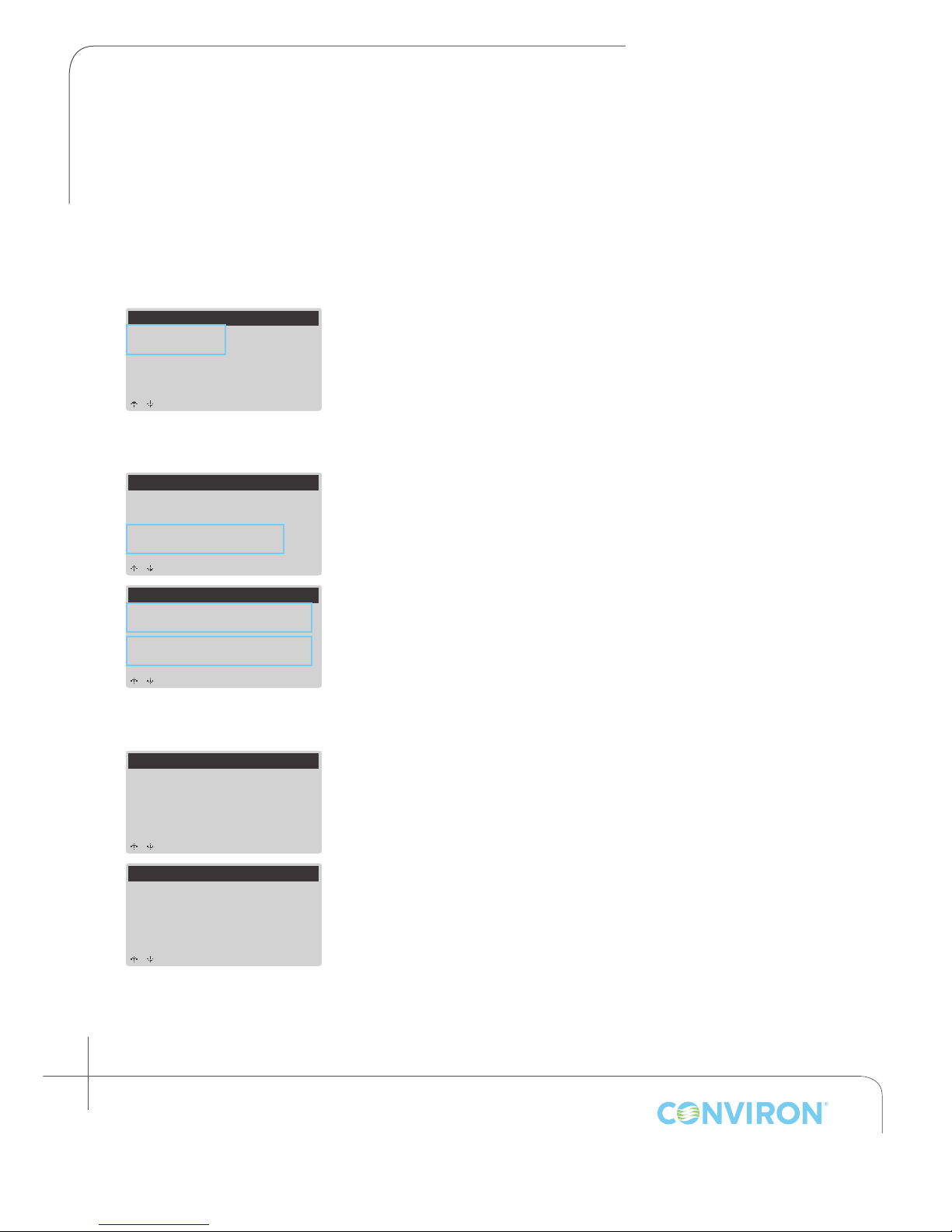
CHAPTER 1 | SERVICE MENU
00000
SYSTEM
from -Status- screen).
9.2 System
The System screens provide general information about controller memory and communications status.
Clock Card
Clock Card:
SYSTEM
Not Working
Permanent Memory:
Working
Memory
Clock Card:
Not Working
Permanent Memory:
Working
SYSTEM
Ext Permanent Memory:
Present + Working
Permanent Mem Writes:
Communications
SYSTEM
Communications:
Disabled
The clock card contains a battery that allows the controller
to maintain time/date settings through power outages and
chamber down time. No modiable settings.
Permanent Memory, Ext (extended) Permanent Memory, and
Permanent Memory Writes all report on the status of the
controller’s memory. No modiable settings.
The communications item will show enabled when a network
card has been installed in the controller. There is no
requirement for modication of this parameter.
to scroll
SYSTEM
Communications:
_nabled
(for network settings
press <Prg> + <Esc>
9-6
Janaury 2016 | 256573R04
Page 57
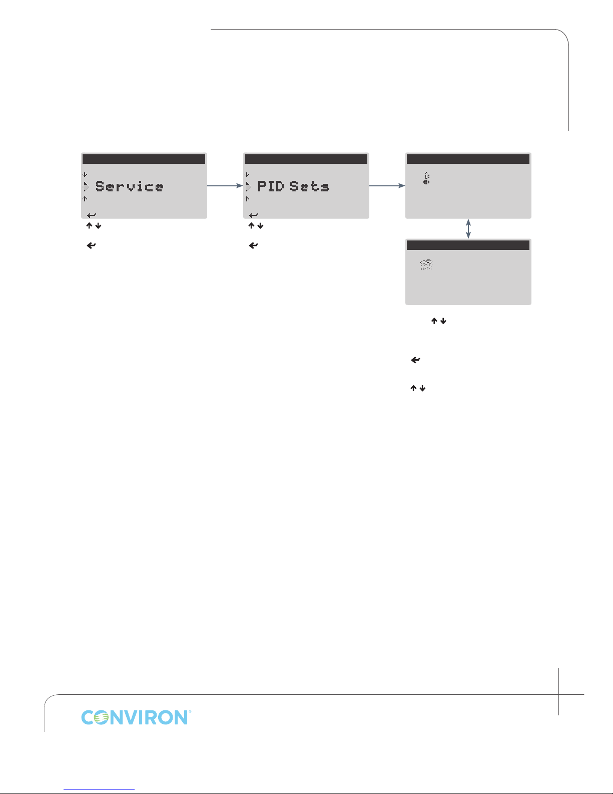
CHAPTER 1 | CMP6010 User Manual
< > to S elect
< > to S elect
9.3 PID Sets
The PID Settings screens contain the proportional, integral, and derivative values for controlled
processes (temperature and humidity). These values are factory set by Conviron, and should not
require modication, except under strict guidance from Conviron Technical Service.
---MAIN MENU---
A larm
S ervice
O ptions
< / > to select Service
< > to accept
---SERVICE MENU---
S ystem
P ID Sets
C onfig
< / > to select PID Sets
< > to accept
PID SETTINGS
Temperature
Proportional:
Integral:
Derivative:
0150
0280
0080
PID SETTINGS
Humidity
Proportional:
Integral:
Derivative:
With cursor selecting screen title,
press < / > to scroll between
Temperature and Humidity PID
settings screens
< > to cycle cursor through
congurable parameters
< / > to congure selected
parameter
<Esc> to exit and return to
Options menu
0150
0280
0080
January 2016 | 256573R04
9-7
Page 58
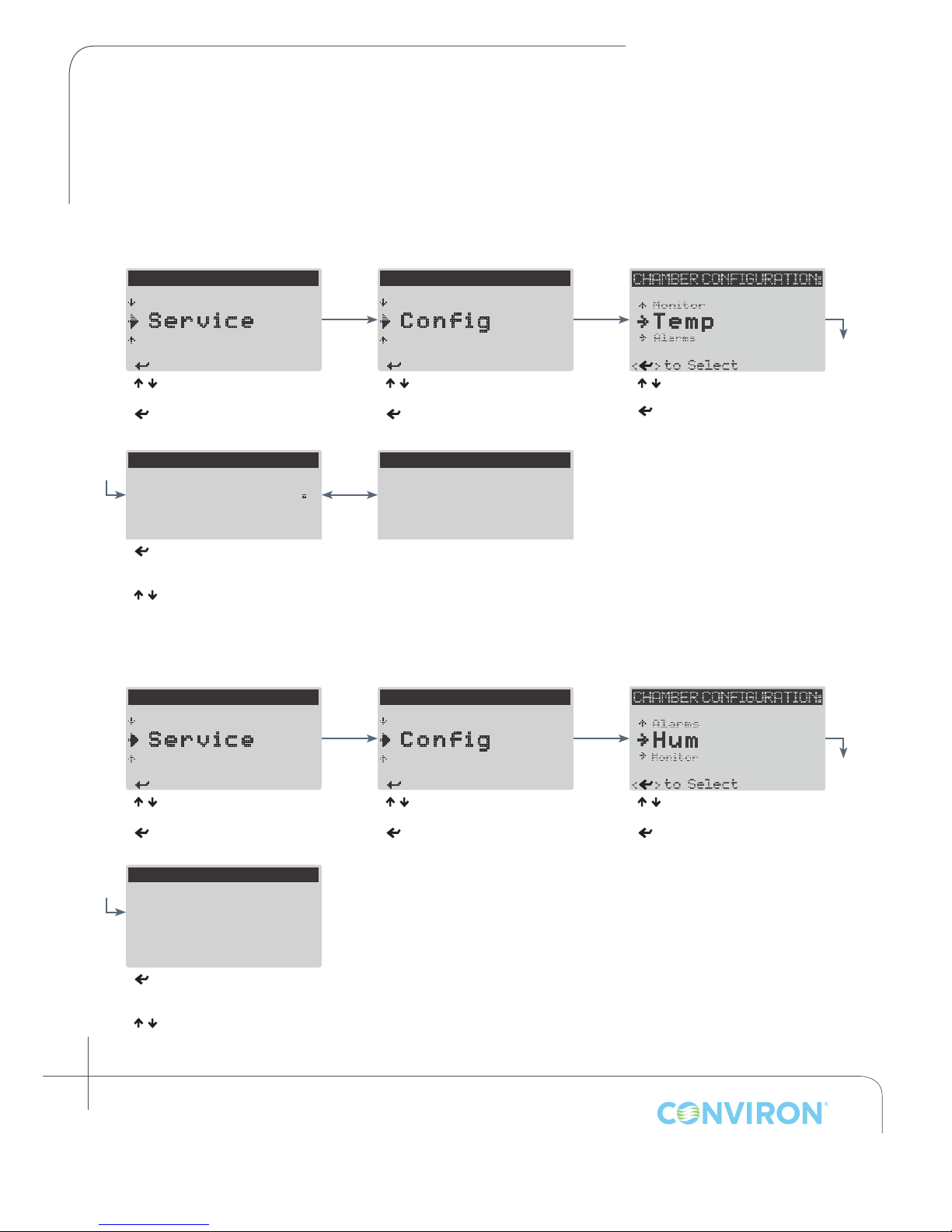
CHAPTER 1 | SERVICE MENU
< > to S elect
< > to S elect
< > to S elect
< > to S elect
<Esc> to Save & Exit
9.4 Cong
The Cong screen contains fundamental settings related to process control and the ability to select
which alarm type (Low Water or Door Open) will monitored by the controller. These settings are
congured at the factory based on chamber type and additional options.
9.4.1 Temperature Process Conguration
---MAIN MENU---
A larm
S ervice
O ptions
< / > to select Service
< > to accept
CHAMBER CONFIGURATION:
Temperature Range:
Valve Type: Stepper
Max Stepper O/P: 100%
<
> to cycle through all congurable parameters (page will scroll
automatically).
< / > to congure selected parameter
04.0 - 45.0 C
---SERVICE MENU---
P ID Sets
C onfig
R eset User
< / > to select Cong
< > to accept
CHAMBER CONFIGURATION:
Enable Boost Heat: No
9.4.2 Humidity Process Conguration
---MAIN MENU---
A larm
S ervice
O ptions
---SERVICE MENU---
P ID Sets
C onfig
R eset User
< / > to select Temp
< > to accept
< / > to select Service
< > to accept
CHAMBER CONFIGURATION:
Humidity Sensor
Type: HM1500
Humidity Range:
000 - 100%RH
< > to cycle through all
congurable parameters
< / > to congure selected
parameter
9-8
Janaury 2016 | 256573R04
< / > to select Cong
< > to accept
< / > to select Hum
< > to accept
Page 59
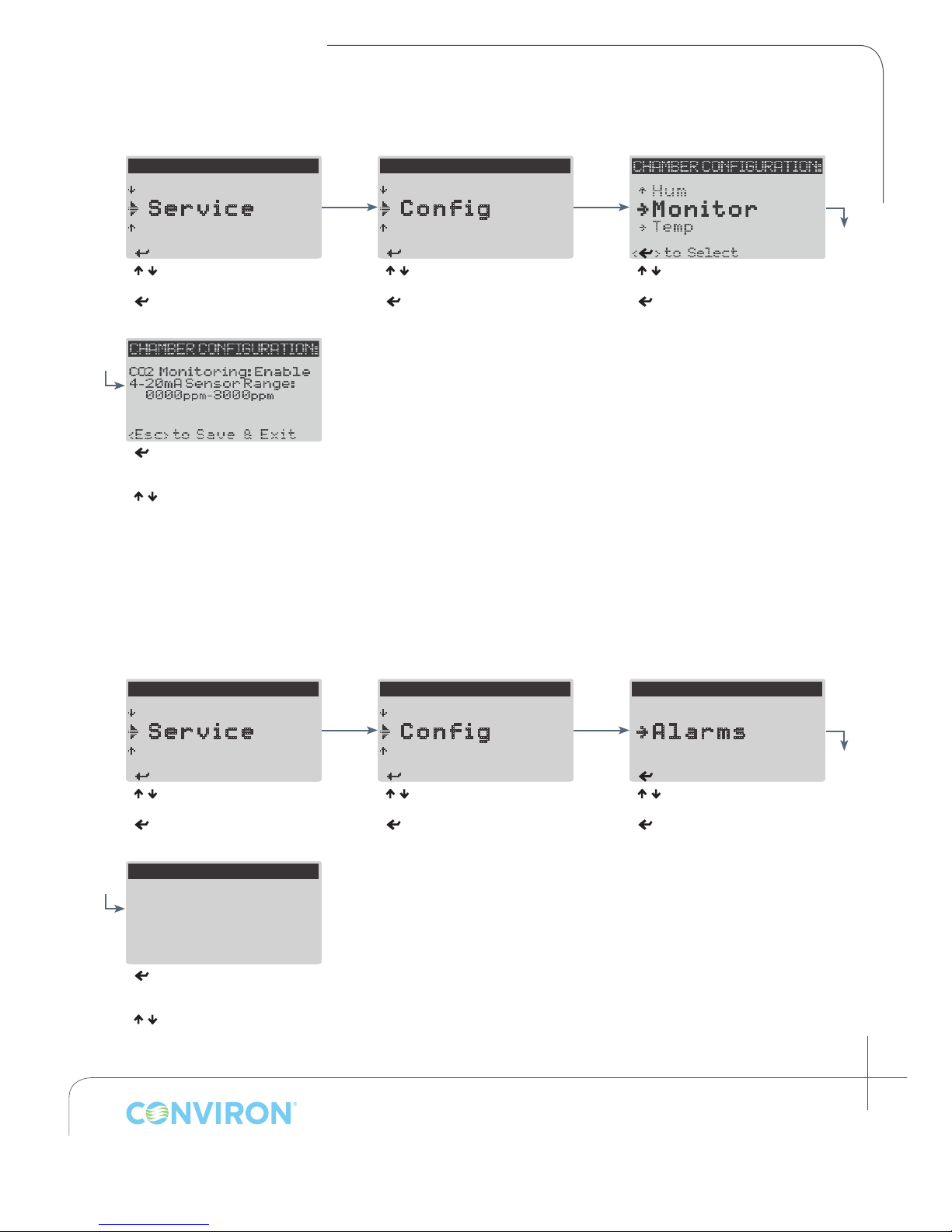
9.4.3 Carbon Dioxide Monitoring Conguration
< > to S elect
< > to S elect
< > to S elect
< > to S elect
< > to S elect
CHAMBER CONFIGURATION:
<Esc> to Save & Exit
CHAPTER 1 | CMP6010 User Manual
---MAIN MENU---
A larm
S ervice
O ptions
< / > to select Service
< > to accept
< > to cycle through all
congurable parameters
< / > to congure selected
parameter
---SERVICE MENU---
P ID Sets
C onfig
R eset User
< / > to select Cong
< > to accept
< / > to select Alarms
< > to accept
9.4.4 Alarm Type Conguration
The standard alarm type congured CMP6010 equipped chambers is the Float Switch alarm. The
controller can only enable one of the two alarm types at any given time. The Door Open alarm is an
optional feature.
---MAIN MENU---
A larm
S ervice
O ptions
< / > to select Service
< > to accept
Door Open Alarm:
Float Switch Alarm:
< > to cycle through all
congurable parameters
< / > to congure selected
parameter
Disabled
Enabled
---SERVICE MENU---
P ID Sets
C onfig
R eset User
< / > to select Cong
< > to accept
CHAMBER CONFIGURATION:
->
T emp
->
A larms
->
H um
< / > to select Alarms
< > to accept
January 2016 | 256573R04
9-9
Page 60
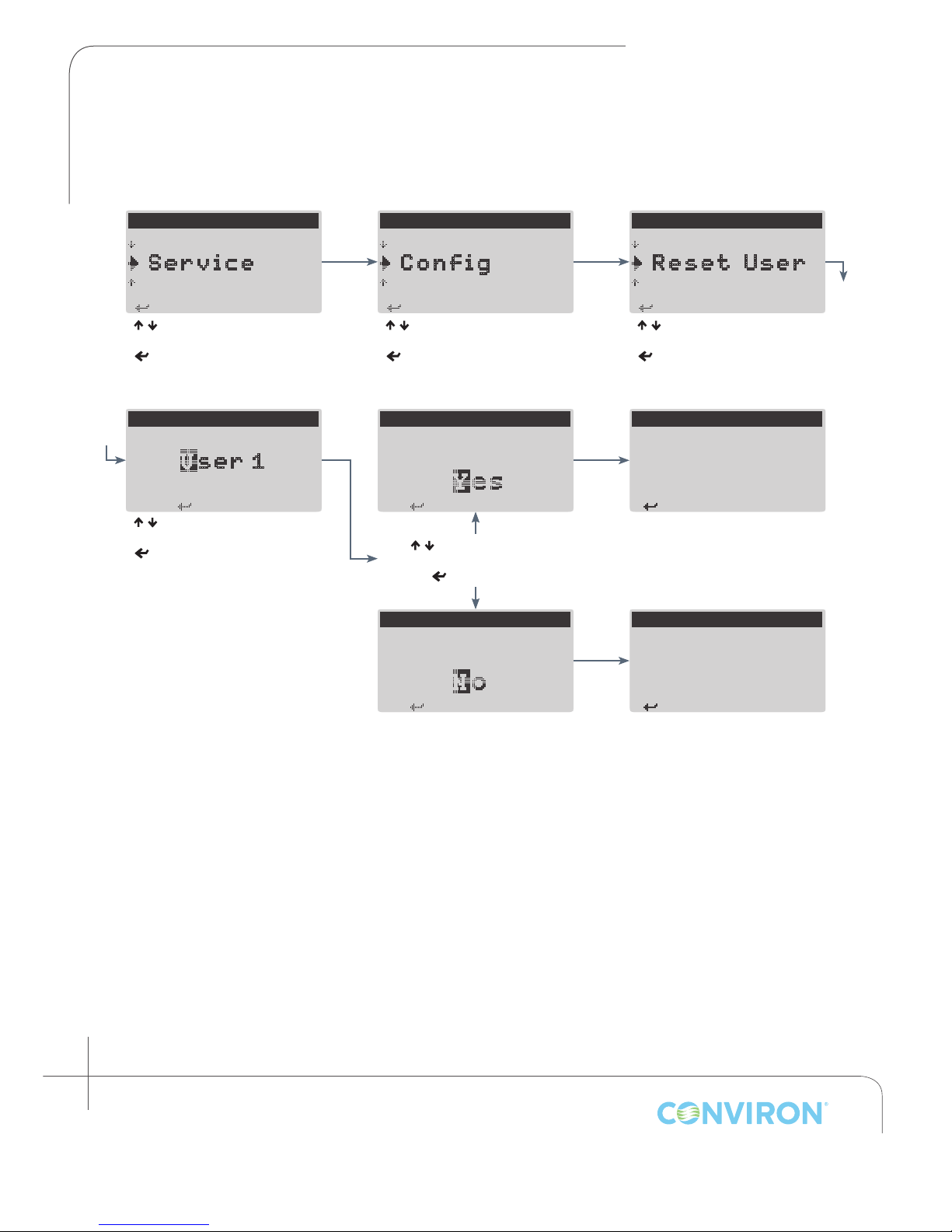
CHAPTER 1 | SERVICE MENU
< > to S elect
< > to S elect
< > to S elect
RESET USER
< > to S elect
to reset User 1?
< > t o continue
to reset User 1?
< > t o continue
< > t o continue
< > t o continue
9.5 Reset User
The Reset User menu allows a User level account to be reset to default settings.
---MAIN MENU---
A larm
S ervice
O ptions
< / > to select Service
< > to accept
Select user to reset:
s er 1
< / > to select user to reset
< > to accept
---SERVICE MENU---
P ID Sets
C onfig
R eset User
< / > to select Cong
< > to accept
RESET USER
Are you sure you want
< / > to select Yes or No
< > to continue
RESET USER
Are you sure you want
---SERVICE MENU---
C onfig
R eset User
I O Status
< / > to select Reset User
< > to accept
RESET USER
User 1 reset.
RESET USER
User restored.
9-10
Janaury 2016 | 256573R04
Page 61

10.0 GLOSSARY
CHAPTER 10 | CMP6010 User Manual
Central Management
System™ (CM)
Chamber The entire unit is called the chamber. Parts of the chamber include
Controller The device which controls chamber operations according to user inputs.
Current Menu Location A black bar at the top of every screen which indicates current
Cursor The cursor identies the currently selected parameter when
Entry
A optional remote control and monitoring system. Contact
Conviron for more information.
the control screen, the electrical panel, the refrigeration system and
the plant growth area (chamber interior).
location on the menu map.
modifying controller settings. It can be either a ashing solid block
(when within the current screen) or a ashing underscore (when
selecting the current menu location), and is toggled by the Enter
< >
key.
An entry designates a program by number, and the number of
times for that program to be run before the controller executes
the next entry. Entries are identied by number on the left side
of the Edit Schedule screen (see section 4.1 Introduction to the
Schedule)
Host Another term for the Central Management system. It is more
commonly used in alarm messages and technical documentation.
Inputs User dened parameters that enable controllers’ activity.
Outputs Switches that control specic devices or conditions within the chamber.
Program A program is a series of timelines, each of which species chamber
environmental conditions --temperature, humidity, and light-- at a
given point in real time. Each program represents a single 24 hour
period, and can contain between 1-24 timelines. The controller
memory can store up to 16 programs.
Set point A set point designates the target value for a controlled parameter.
For example, 25°C is a temperature set point.
January 2016 | 256573R04
10-1
Page 62

CHAPTER 10 | GLOSSARY
GLOSSARY
Schedule The numbered list of entries which the controller executes
sequentially in ascending order.
Timeline A timeline designates a set point value for each controlled
parameter at a specied point in real time. Each program in the
CMP6010 can store up to 24 timelines.
10-2
Janaury 2016 | 256573R04
Page 63

Page 64
®
Conviron - Head Ofce
Winnipeg, Canada
Toll Free: 1 800 363 6451
Conviron Europe Ltd.
Cambridgeshire, UK
Tel: +44 (0)1638 74 1112
Conviron - China
Shanghai, China
Tel: +86 21 62147582
Conviron - US
Pembina, USA
Toll Free: 1 800 363 6451
www.conviron.com
ISO9001
©2016 Controlled Environments Limited. Conviron is a registered trademark of Controlled Environments Limited. All other trademarks are the property of
their respective owners. Information subject to change without written notice.
Conviron GmbH
Berlin, Germany
Tel: +49 30 367 006 60
Conviron - Australia
Melbourne, Australia
Tel: 1300 438 912
 Loading...