

Page 1

Conviron CMP4030
User Guide
For controllers using:
• Version 6.0 software
• Independent temperature shut-off (ITSO)
• External battery
This Guide belongs to: _____________________________________________
Published by
Controlled Environments Limited
590 Berry Street
Winnipeg. Manitoba. Canada
R3H 0R9
November 2002
Copyright © 2003 Controlled Environments Limited. All rights reserved.
Page 2
Safety for you and the equipment
Your safety
Warning – High voltage hazard:
Some procedures in this manual involve working inside a live control
Equipment safety
Electrostatic
discharge (ESD)
cautions
Battery expiry /
Memory-loss
cautions
panel. Do
and experience. Proceed only with appropriate safety precautions.
Electrostatic hazard:
Many electronic components in the control system can be damaged or
destroyed by electrostatic discharges (ESD) that you cannot even feel.
You can discharge 5000 volts without feeling it but this voltage is
strong enough to destroy many electronic components of the system.
If you handle system components, you MUST wear a grounded
wrist strap. The best ground is to the triac heat sink.
In addition:
! Do not let anyone that is not wearing a grounded wrist strap work
on the control panel.
! Do not touch any parts or conductors on the board even when you
are wearing a grounded wrist strap.
! Do not lay paper on static-sensitive parts.
! Ship components to Conviron in anti-static bags.
! Make sure everyone that may work on the control panel is aware
of these procedures.
Failure to follow proper ESD precautions may void the warranty!
Memory-loss hazard:
A continuous supply of electricity to the controller is essential to
preserve its memory. If its memory is lost, the controller cannot
operate and will have to be replaced.
An external battery provides backup for the regular supply of electricity
for brief periods when the regular supply is not available.
The battery must be replaced (see Chapter 7: Maintenance and
Troubleshooting) at intervals
To promote battery life:
• Keep the controller disconnect switch
switch to turn power for the chamber on and off).
• Keep ambient temperatures within the range of human comfort.
Operation warning:
Always wait at least three (3) minutes after completing any procedure
before turning off the controller.
Wait at least 10 seconds before turning the controller on again.
NOT attempt them unless you have appropriate knowledge
NOT exceeding 5 years.
ON (use only the start/stop
Copyright © 2003 Controlled Environments Limited. All rights reserved.
Page 3

User Guide Table of Contents
Chapter 1 – The CMP4030
Chapter 2 – The Status Screen
Chapter 3 – Programming
Chapter 4 – Alarm Management
Chapter 5 – Login and Security Procedures
Chapter 6 – Setting Options and Logging Data
Chapter 7 – Maintenance and Troubleshooting
Appendix A – Labels
Appendix B – Alarm Messages
Appendix C – New Features of v6.0 Software
Appendix D – The Psychrometric Chart
Glossary
Index
Copyright © 2003 Controlled Environments Limited. All rights reserved.
Page 4

Index
Activating security, 5-6
Alarm
indicators, 4-6
labels, Appendix A
messages, Appendix B
options, 4-4
priority values, 4-5
programming, 4-6
responding to, 4-7
screen fields, 4-3
screen, 4-2
status field codes, 4-7
Auxiliaries, programming, 3-22
Auxiliary program example, 3-23
Binary mode, 3-19
Chain program screen fields, 3-16
Chain program screen, 3-15
Chaining
a program to itself, 3-16
programs, 3-15
several programs, 3-17
Chaining, 3-15
Chamber ID number, 2-4
Chamber information, 2-4
Changing a timeline, 3-9
Changing your password, 5-4
Chart recorder field, 2-5
Chemical drier, setting the, 6-5
Cleaning and Inspecting Control Panel
Components, 7-2
Clearing SRAM Memory and Recalibrating
the Touch Screen, 7-5
CMP4030 features, 1-4
CMP4030 security procedures, 5-1
CO2 / Auxiliary (CO2) Selector, 2-3
Controller programming, 3-7
Controller software updates, 7-8
Conviron Technical support, 1-7
Creating a graph, 6-10
Day/night program sample, 3-11
Default user IDs, 5-7
Defrost, setting , 6-5
Dehumidification, setting, 6,5
Deleting
a program, 3-14
a timeline, 3-9
cell settings in a timeline, 3-9
Diagnostic screen fields, 7-4
Diagnostic screen, 7-3
Entering timelines, 3-8
Event mode, 3-19
Expandability of CMP4030, 1-5
Exporting Logged Data, 1-5
External Controller Battery, Replacing, 7-6
Features of CMP4030, 1-4
Features of Version 6.0 software, 1-3
see also, Appendix C
Graph, creating a, 6-10
Independent Temperature Shut Off, 4-8
Inserting a timeline, 3-9
Inserting timelines in a ramp, 3-11
Inspecting and Cleaning Control Panel
Components, 7-2
ITSO, 4-8
Lighting zone selector, 2-3
Logging options, setting the, 6-6
Logging out, 5-4
Login screen fields, 5-3
Login screen, 5-2
Memory loss cautions, 1-6
Modes of operation, 3-19
Multi-day programming, 3-15
Optional alarm indicators, 4-6
Options screen fields, 6-3
Options screen, 6-2
Output Status Indicator, 2-4
Password change, 5-4
Program
indicator field, 2-4
screen fields, 3-3
screen toolbar, 3-4
screen, 3-2
table icons, 3-3
table toolbar, 3-5
table, 3-3
verifying a, 3-12
Programming
an alarm, 4-5
auxiliaries, 3-22
in step mode, 3-12
multi-day, 3-15
the controller, 3-7
system settings, 6-4
Psychrometric chart, Appendix D
Ramping, 3-7
Recalibrating the Touch Screen and
Clearing SRAM Memory, 7-5
Relative humidity zone selector, 2-3
Replacing External Controller Battery, 7-6
Responding to an alarm, 4-7
1
Page 5

Index
Running a chained program, 3-18
Save program screen fields, 3-13
Save program screen, 3-13
Saving a program, 3-14
Saving Programs to Disk, 1-5
Security
screen procedures, 5-4
levels and functions, 5-5
activating, 5-6
procedures for the CMP4030, 5-1
Setting the
chemical drier, 6-4
defrost, 6-5
dehumidification, 6-5
logging options, 6-6
SRAM, clearing, 7-5
Standard alarm indicators, 4-6
Status screen fields, 2-2
Status screen, 2-1
Step mode program sample, 3-12
Storing logged data, 6-7
System settings, programming, 6-4
Table cell information, 3-5
Technical support, Conviron, 1-7
Temperature zone selector, 2-3
Timelines, 3-8
Touch screen, 1-4
Trendgraph screen fields, 6-8
Trendgraph screen, 6-8
User IDs, default, 5-7
Verifying a program, 3-10
Version 6.0 software features, 1-3
see also, Appendix C
Zone selectors, 2-2
2 CMP4030 User Guide
November 2002
Page 6

Chapter 1: The CMP4030
Contents
This manual is intended for users with moderate experience with
computers or with Conviron products. This manual provides instruction
on:
• starting the controller
• setting up programs
• logging data
• understanding and managing alarms
• performing simple troubleshooting and maintenance tasks
Chapter 1: The CMP4030
This chapter describes:
• the features and functionality of Version 6.0 software
• the features of the CMP4030
Chapter 2: The Status Screen
This chapter describes:
• how to use fields on the Status screen
Chapter 3: Programming
This chapter describes:
• how to create timelines
• how to save and chain programs
• how to view programs graphically
• the functionality of auxiliaries
• how to open programs saved on disk
1-1
Page 7

Chapter 1: The CMP4030
Chapter 4: Alarm Management
This chapter describes:
• the function of alarms in a program
• how to set alarms
• how to respond to alarms
Chapter 5: Security
This chapter describes
• log in procedures
• security
Chapter 6: Setting Options and Logging Data
This chapter describes
• the Options screen
• the Trendgraph screen
• options for logging data
• options for viewing collected data
Chapter 7: Maintenance and Troubleshooting
This chapter describes
• starting the CMP4030 after a power outage
• how to use the diagnostic screen
• basic problem solving
This manual also contains a glossary and four appendices.
Appendix A – Labels
Appendix B – Alarm Messages
Appendix C – Features of Version 6.0 Software
Appendix D – The Psychrometric Chart
The software contained in the CMP4030 controller is the property of Conviron and its
licensors and is protected by copyright law.
1-2 CMP4030 User Guide
November 2002
Page 8

Features of Version 6.0 Software
Features of Version 6.0 Software
Boot up
Screen
Functionality
Alarms
Options
Programming
Security
Trendgraph
• boot up is faster than in previous versions
• the functionality of the screen is faster, easier and more intuitive
• a set button/keypad replaces the scrolling arrows used in previous
versions
• alarms have enhanced error reporting and display user friendly
messages
• the control of humidification and the defrost operation have been
enhanced
• time can be adjusted without losing data
• a program now maintains the current condition if it is unchained or if
the next program in the chain is corrupt
• creating and managing security ID’s is more straightforward and the
entire process is completed on one screen
• data is traced on screen many times faster than in previous versions
See Appendix C for a complete list of V6.0 features.
1-3
Page 9
Chapter 1: The CMP4030
Features of the CMP4030
The Touch Screen
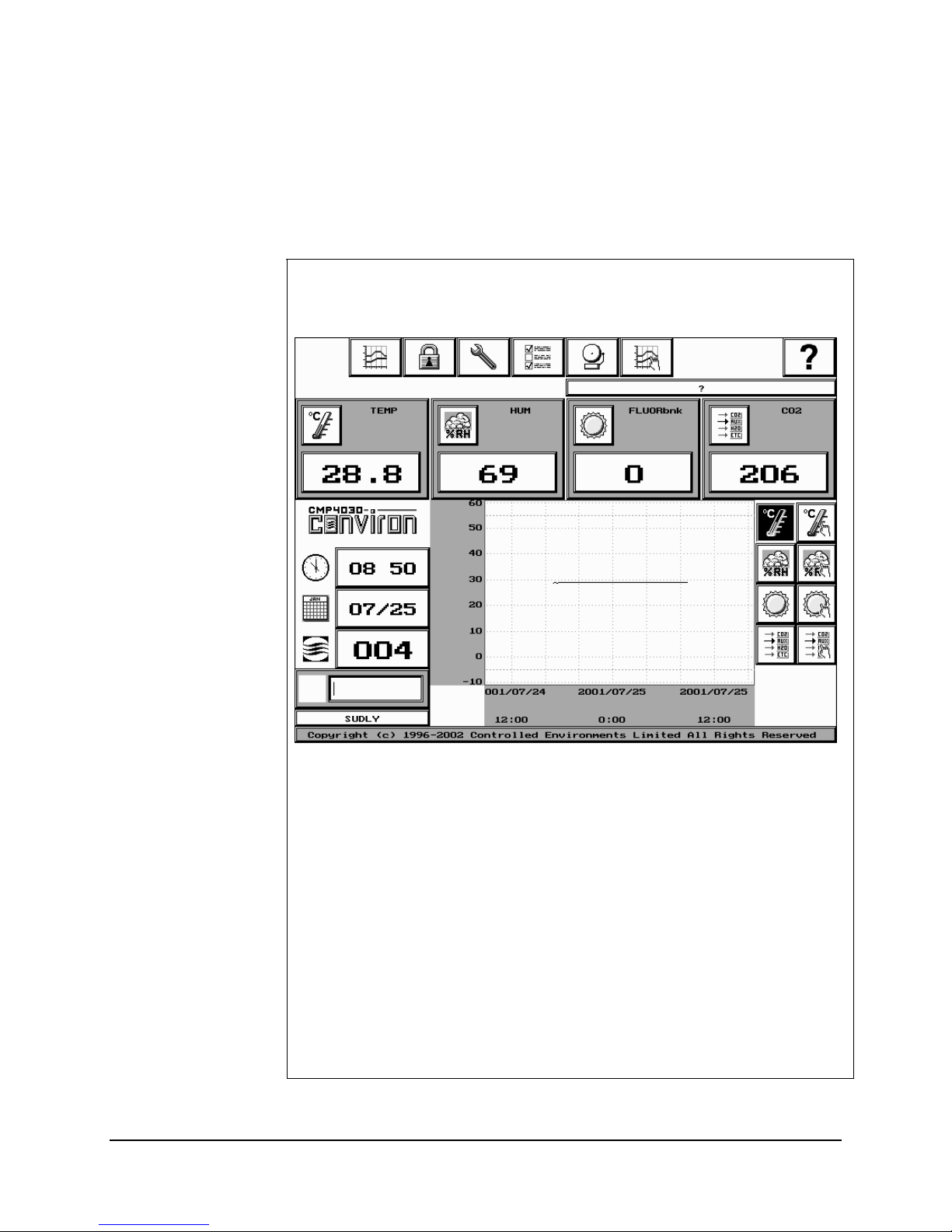
The system uses a Liquid Crystal Display (LCD) panel with an
The CMP4030 Local Control System (LCS) is used to control the plant
growth chamber. The ‘brain’ of the LCS is the Version 6.0 software.
integrated touch screen as the user interface.
The touch screen provides the facility to:
• program controls
• assist qualified personnel to service the chamber
• control temperature
• control lighting
• control relative humidity
The screen measures 210mm x 158mm (8.3" x 6.2").
Information on the touch screen is easy to read because the screen is
backlit.
Most icons are “touchable” and initiate a controller action when they are
touched. In this manual, “touchable” icons are called buttons.
When a button is touched, it will flash and the controller will beep.
1-4 CMP4030 User Guide
November 2002
Page 10
Features of the CMP4030
Important:
The screen has a backlight saver. After five minutes of inactivity, the
screen goes blank. Touch the screen to reactivate the display.
Do not touch the screen with sharp or pointed objects. Use your
fingertip or the eraser end of a pencil.
On-line help
To access on-line help, touch the Help button, then the field or button
for which help is required.
Saving Programs to Disk
Programs can be saved on disk and copied for use with other
chambers. The chamber must be equipped with a disk drive installed to
use this feature.
Caution! If a program is to be used on another chamber, the chambers
must have the same configuration.
Exporting Logged Data
Data can be exported to other software such as spreadsheets or word
processors. The data files are easily imported into programs such as
Excel
Expandability
• they must have the same number and type of program zones in
the program table
• the program zones must be in the same order
.
The CMP4030 is a flexible control system and adding capacity is a
simple process. If there is a need to control additional devices or
equipment, hardware and software upgrades are available. Contact
Conviron Customer Care.
Security
Users can be assigned User ID’s and passwords to ensure that only
authorized staff make program changes.
1-5
Page 11

Chapter 1: The CMP4030
Memory-loss Cautions
Memory-loss hazard:
A continuous supply of electricity to the controller is essential to
preserve its memory. If memory is lost, the controller will not function
and cannot be repaired.
An external battery provides backup when the regular power supply is
unavailable. To ensure that the external battery has power, replace it
every 5 years.
Instructions for replacing an external battery are provided in Chapter 8:
Maintenance and Troubleshooting.
To promote battery life:
Leave the controller disconnect switch
ON. To turn the chamber on
and off, use the start/stop switch.
Keep ambient temperatures within the range of human comfort.
1-6 CMP4030 User Guide
November 2002
Page 12
Conviron's Technical Support
Conviron's Technical Support
Head Office
(Sales and Service)
Conviron Customer
Care
Important:
When contacting Conviron for technical support, please provide the
chamber Serial Number, which is located on the rating plate on the
side of the chamber.
Customer Services
Controlled Environments Limited (CONVIRON)
590 Berry Street, Winnipeg, Manitoba, R3H 0R9
Canada
Sales Department Email: [email protected]
Toll free in North America
Regular telephone
Fax
E-mail
Web address
1-800-363-6451
1-204-786-6451
1-204-783-7736
www.conviron.com
1-7
Page 13
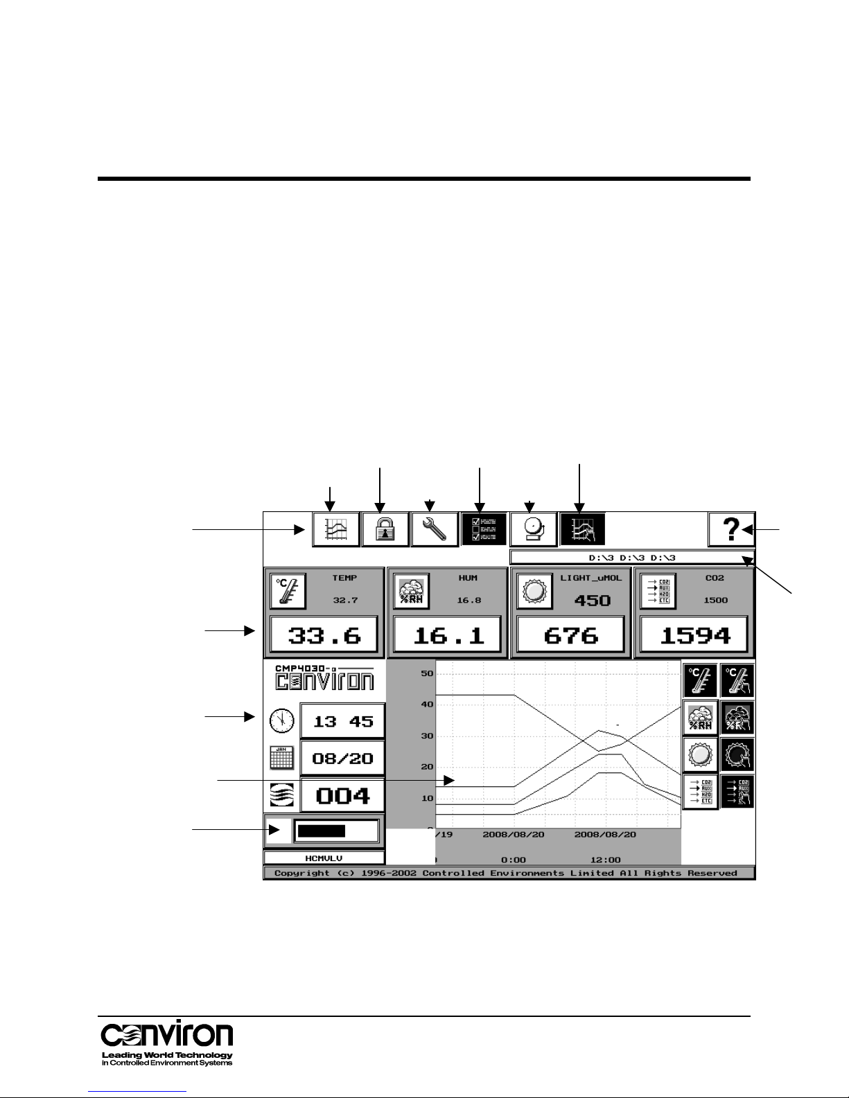
Chapter 2: The Status Screen
ecorder
r
The Status Screen
Toolbar
Zone
Selectors
The Status screen provides a comprehensive overview of the
chamber’s current program and conditions.
This chapter describes:
• how to use and read status screen fields
The Status screen is displayed when the controller is powered on.
Trendgraph
button
Security
button
Diagnostics
button
Options
button
Program
button
Alarm
button
Help
Program
Indicato
Chamber
Information
Chart
R
Output
Status
Indicator
2-1
Page 14
Chapter 2: The Status Screen
g
Status Screen Fields
Toolbar
Trendgraph
button
Security button
Diagnostics
button
Options button
Alarm button
Program button
The Status Screen Toolbar provides access to other CMP4030
functions.
Touch to access the Trendgraph screen.
Touch to access the Security screen.
Touch to access the Diagnostics screen.
Touch to access the Options screen. A flashing Options button
indicates that data is being logged.
The Options screen can be accessed at any time however the
date, time and logging options cannot be changed if a program is
running.
Touch to access the Alarms screen.
A flashing Alarm button indicates an active alarm.
Touch to access the Program screen.
A flashing Program button indicates that a program is running.
Help button
Zone Selectors
Program
Settin
Current
Conditions
s
Temperature
To access on-line help, touch the Help button, then the field or
button for which help is required.
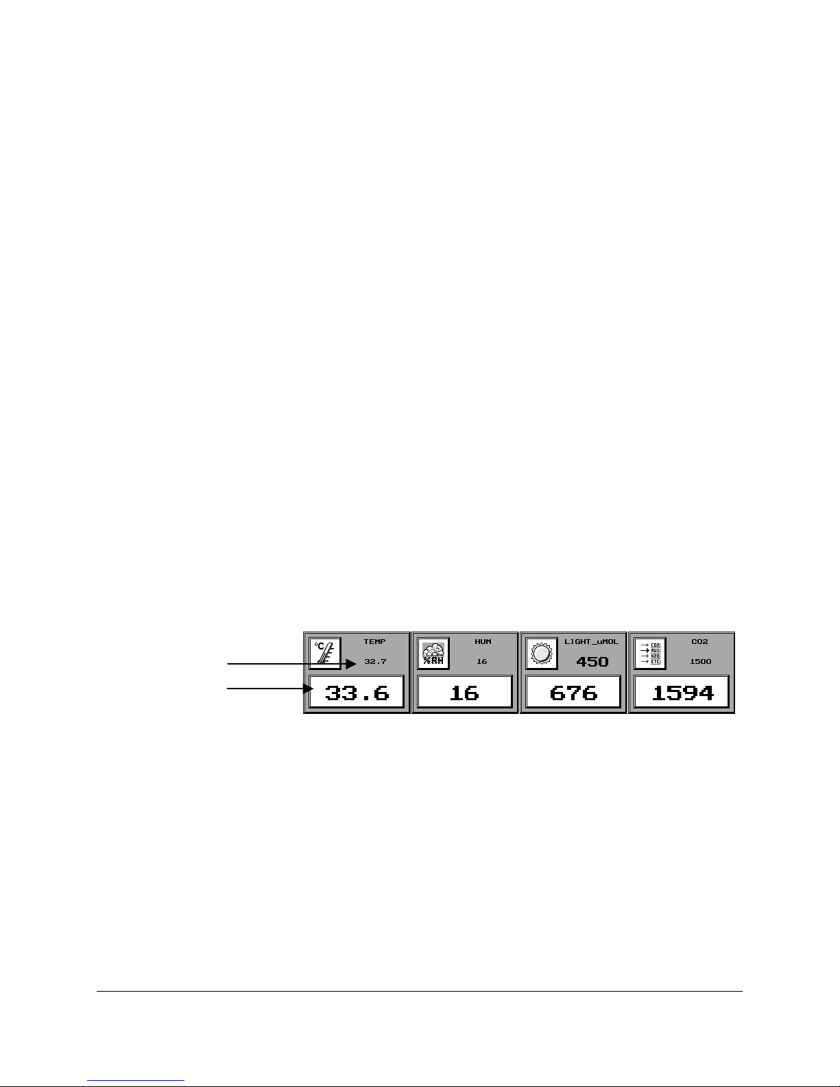
A zone is a specified area of control and/or monitoring.
Zone selectors display the current program’s settings and actual
values of the conditions in the chamber.
• Current conditions are displayed in the white fields.
• Program settings are displayed in the gray areas.
• If a zone does not have a program setting but is being
monitored, the condition will be displayed in both the gray
area and the white field of the zone selector.
• Each zone display has a zone selector button that can
display multiple sub-zones, based on chamber options
such as: soil temperature, auxiliary lighting, lamp loft
temperature, etc.
Displays chamber temperatures in degrees Celsius.
2-2 CMP4030 User Guide
November 2002
Page 15

Status Screen Fields
(TEMP) Zone
Selector
Relative Humidity
(HUM) Zone
Selector
Lighting Zone
(LIGHT_uMOL)
Selector
• The default reading, TEMP, is the control zone.
• If there is more than one temperature zone, touch the
zone selector button to display the readings for each
zone. The Chart Recorder will display each zone as it is
selected.
Displays the relative humidity percentage.
• The default reading, HUM, is the control zone.
• This feature is valid only if the chamber is equipped with
additive humidity and/or dehumidification.
• If there is more than one relative humidity zone, touch the
zone selector button to display the settings for each of the
zones. The Chart Recorder will display each zone as it is
selected.
Displays values in banks, percentage of full power, or in units
such as micromoles (µmol), depending on chamber options.
• If there is more than one set or type of lights, touch the
zone selector button to display the settings for each type.
The Chart Recorder will display each zone as it is
selected.
CO2 / Auxiliary
(CO2) Selector
(optional)
Displays one of the following depending on chamber options:
• CO
concentration, in parts per million, in the plant growth
2
area.
• An auxiliary on-off event
• Other chamber parameters
Touch the zone selector button to display the possible zones.
The Chart Recorder will display each zone as it is selected.
2-3
Page 16
Chapter 2: The Status Screen
Chamber Information
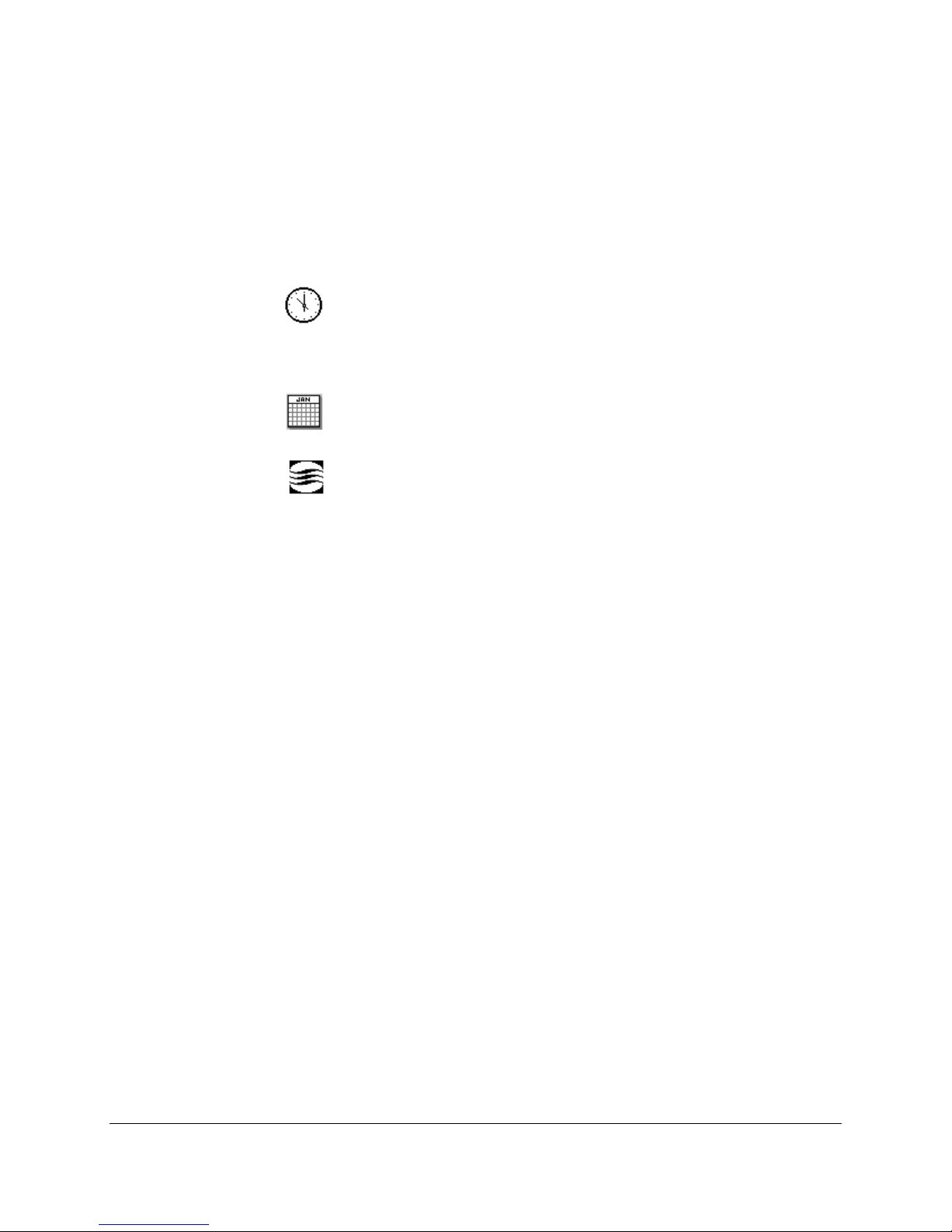
The Chamber Information fields display the current date, time,
chamber number and output status.
These settings are entered in the Options screen. Refer to
Chapter 6, Setting Options and Logging Data, for more
information.
Time – current time in 24-hour format.
Note: Data will be overwritten if time is adjusted forward for any
reason such as Daylight Savings Time.
Date – date in MM/DD format.
Chamber identification number – chamber ID.
The Chamber ID identifies the chamber to the Central Control
System (CCS).
• the factory default ID of 100 must be changed prior to
connection to a CCS.
• duplicate IDs on a CCS network cannot be used.
Output Status Indicator
An output is a switch that controls a specified device, such as a
valve or a bank of lights.
The Output Status Indicator provides a graphical view of the
operation of the selected output.
By touching the white square on the left side of the indicator, the
user is able to cycle through the various control system outputs.
• when the output is fully off, the bar graph in the indicator
does not display.
• when the output is fully on, the bar graph appears black.
• modulating or proportional outputs will display a bar
graph between 0 and 100% on.
Program Indicator
The Program Indicator field displays the program that is currently
running as well as programs that are chained to it.
If a program cannot be run, the program indicator field will
display one of the following warning messages.
– cannot open current file
? no chain specified
! cannot open chain file
✻ chain file has incorrect format (and cannot be run)
2-4 CMP4030 User Guide
November 2002
Page 17
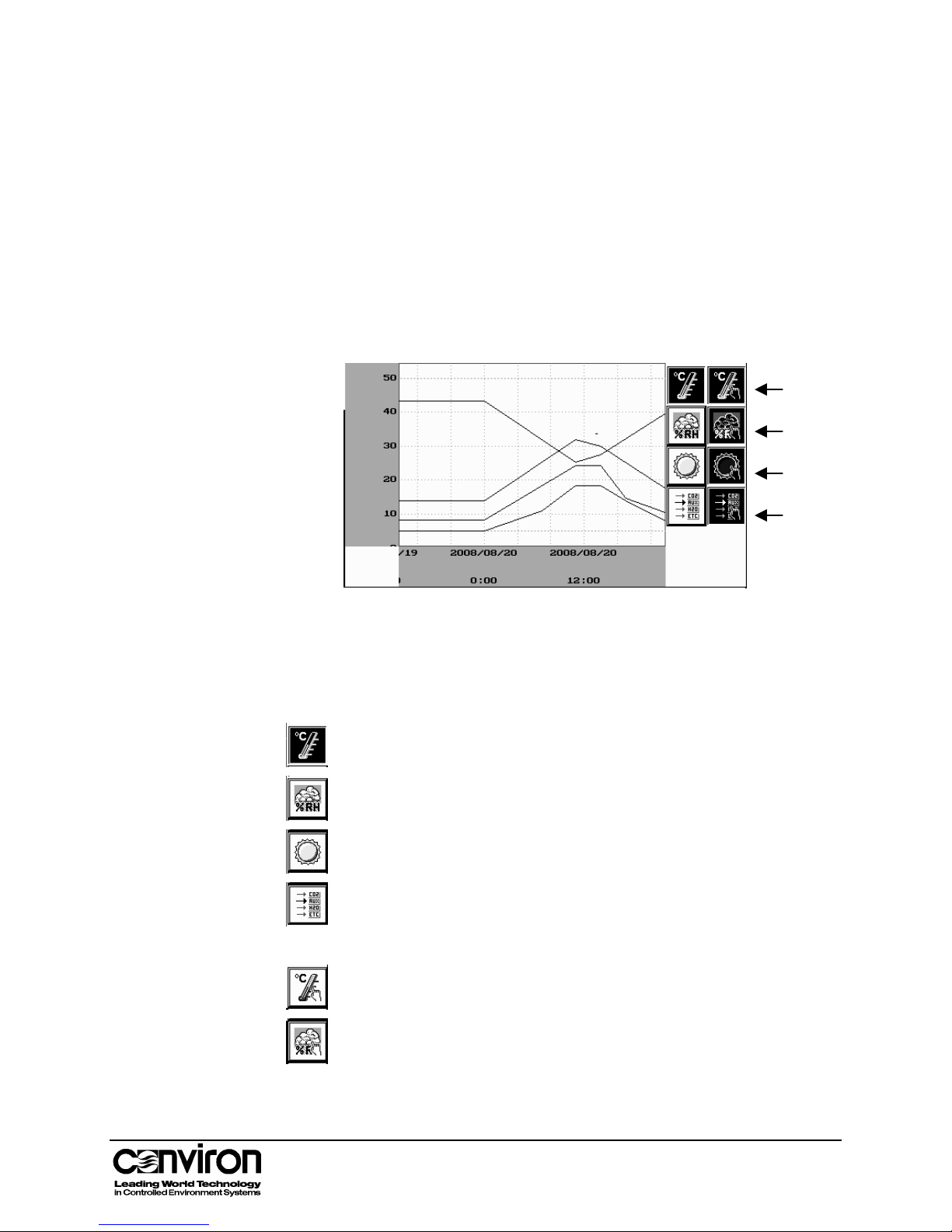
Chart Recorder
Status Screen Fields
The chart recorder provides the facility to view a charted history
of four programmed zones including:
temperature
relative humidity
lighting
CO
and/or auxiliaries
2
The recorder is comprised of a graph and eight buttons.
The eight buttons represent the actual and programmed
conditions for each of the four zones.
Temperature
Relative Humidity
Lighting
CO
/Auxiliary
2
Touch the corresponding zone button to display a charted history
of the zone. When a button is selected, it will appear darkened.
Actual
The actual chamber temperature is charted constantly. This
button will always appear darkened.
Touch to chart humidity data
Touch to chart lighting data
Touch to chart CO
or auxiliary data
2
Programmed
Touch to chart the temperature program
Touch to chart the humidity program
2-5
Page 18
Chapter 2: The Status Screen
Touch to chart the lighting program
Touch to chart the CO
or auxiliary program
2
The Chart Recorder displays thirty-two hours of graphing time.
This includes the previous 24 hours and the next 8 hours.
Note: The controller does not have the facility to read the next
day’s program.
Note:
Multiple zones can by simultaneously charted but the scales
differ for each condition. When viewing several zones on the
Chart Recorder, the scale displayed will relate to the zone that
was most recently charted.
We recommend that the chart be used to view the programmed
and actual conditions of one zone at a time.
2-6 CMP4030 User Guide
November 2002
Page 19

Chapter 3: Programming
This chapter introduces procedures for programming the CMP4030 using the Program screen.
The settings entered in the Program screen control conditions in the plant growth chamber.
This chapter describes:
• The Program screen and toolbar
• Programming the CMP4030
• Multi-day programming
• Managing programs
• How to program auxiliaries
3-1
Page 20
Chapter 3: Programming
g
g
g
g
g
g
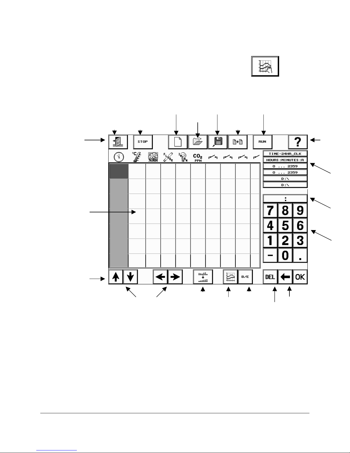
The Program Screen
Program Screen
Toolbar
Program
Table
To access the Program screen, touch the Program
button in
the Status toolbar. The Program screen will appear and will display the
last program that was opened.
Exit
Stop
Pro
ram
New
Pro
ram
Open
Pro
ram
Save
Pro
ram
Chain
Pro
ram
Run
Pro
ram
Help
Table Cell
Information
Number
Display
Program Table
Toolbar
Keypad
Scroll Buttons
Sort
Graph
Program
Binary Event
Switch
Backspace
Delete
3-2 CMP4030 User Guide
November 2002
Page 21
Program Screen Fields
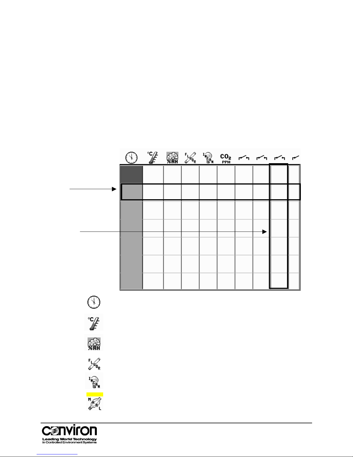
The Program Table
• Each Row of the program table represents a Timeline.
• Each Column represents a Zone.
Program Table Icons
Each icon at the top of the table corresponds to a chamber zone. The
configuration of the controller will determine which zones are displayed.
If the chamber does not have a control for a specific condition, a zone
for that condition will not be displayed.
Row
(Timeline)
The Program Screen
Column
(Zone)
Time –The start time of the timeline in a 24-hour format.
Temperature –The temperature in degrees Celsius.
Relative Humidity –The percent relative humidity.
Fluorescent lighting –The fluorescent lighting in discrete levels, as a
percentage of full power, or in micromoles/m
Incandescent lighting –The incandescent lighting in discrete levels or
percentage of full power.
2
/s.
Metal halide lighting –The metal halide lighting in discrete levels.
3-3
Page 22

Chapter 3: Programming
High-pressure sodium lighting –The high-pressure sodium lighting in
discrete levels.
Carbon dioxide –The level of CO2 in parts per million
Timer – The timer, in seconds.
Speed control or intensity –The percentage of full power, usually for
fan speed control.
Auxiliary switch – switch an auxiliary device in binary or event mode.
Program Screen Toolbar
Exit button
Stop Program
button
New Program
button
Touch the Exit button to return to the Status screen.
Touch the Stop Program button to stop a running program.
Touch the New Program button to clear the current program table
and open a new program table.
Open Program
Touch the Open Program button to open an existing program.
button
Save Program
button
Chain Program
button
Touch the Save Program button to save a program. If the
program is not saved it will be lost if the controller is powered off.
Touch the Chain Program button to link the program to another
program. This procedure is required to make programs run
continuously. If a program is not chained, it will stop at midnight.
Run Program
button
Touch the RUN button to start the displayed program. When a
program is running, the Run Program button on the Program
screen and the Program button on the Status screen flash.
Help button
To access on-line help, touch the Help button, then the field or
button for which help is required.
3-4 CMP4030 User Guide
November 2002
Page 23
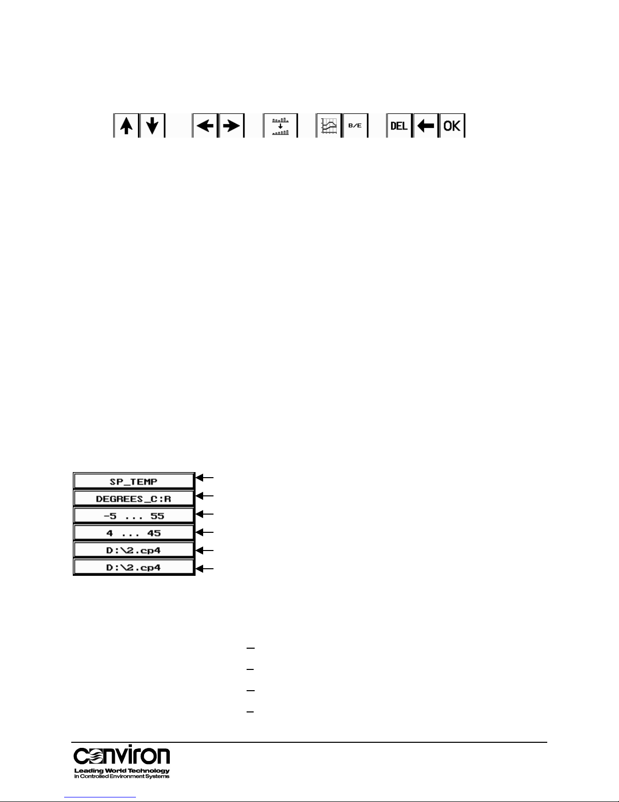
The Program Table Toolbar
The Keypad
Up/Down Scroll
Left/Right Scroll
Sort
Graph Program
Binary/Event
Switch
The Keypad
Number Display
Backspace
Delete
OK
Table Cell Information
Use to move the program table up or down.
Use to move the program table left or right.
Touch to sort timelines chronologically. When a program is
saved, timelines sort automatically.
Touch to view a graph of the program for the active zone.
Touch to set an auxiliary to Binary or Event mode.
As numbers are touched in the keypad, they will display in the
Number Display field. A colon will display for time entries only.
The decimal will function for temperature set points only.
Touch the Backspace key to clear a digit.
Touch the DEL button to delete an entry.
Touch OK to enter the value in the Number Display field into the
active table cell.
Table Cell fields display information specific to the active cell in the Program table.
Label
Active Cell Units
Active Zone Alarm Limit Range
Active Zone Operating Range
Current Program Path and Number
Label
Active Cell Units
Chained Program Path and Number
Indicates the label for the active zone
Indicate the unit of measurement and mode of operation for the
active zone. There are four modes of operation: R, S, B and E.
R
amp – The state changes gradually between timelines
S
tep – The state changes instantly between timelines
B
inary – Auxiliary operates in On/Off mode.
E
vent – Auxiliary cycles on for a specified period of time.
3-5
Page 24

Chapter 3: Programming
Active Zone Alarm
Limit Range
Displays the range of settings for the alarm limits that apply to
the active zone.
Active Zone
Operating Range
Chained Program
Displays the chamber operating range for the active zone.
Displays the chained program path and number.
Path and Number
3-6 CMP4030 User Guide
November 2002
Page 25
Programming the Controller
There are four major steps to completing a program.
1. Entering timelines
2. Saving the program
3. Chaining the program
4. Running the program
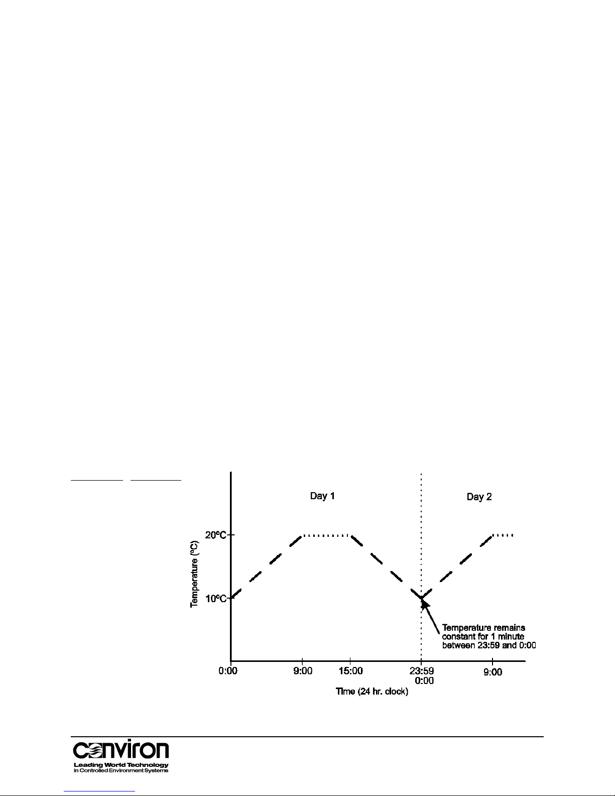
Ramping
Ramping means that the conditions in the chamber change steadily
between timelines.
Most control zones in the chamber, such as temperature, relative
humidity and CO
operate in ramp mode. For example, in the graphed
2,
program below, the chamber temperature gradually rises from 10º at
0:00 until it reaches the 20º at 9:00.
Note: The CMP4030 does not automatically ramp across midnight
because it does not read the next day’s program. Instead, the controller
runs the conditions in the last program timeline until midnight.
When one program ends and the next program begins (at midnight), the
CMP4030 opens the program file for the new day and reads the first
timeline regardless of the program’s time settings.
It is important that programs are well defined so that the controller
interprets the settings as intended. To avoid problems,
Time
0:00
9:00
15:00
23:59
Temp
10º
20º
20º
10º
• Start programs at 0:00 and end them at 23:59
• Program interim settings
3-7
Page 26
Chapter 3: Programming
1. Entering Timelines
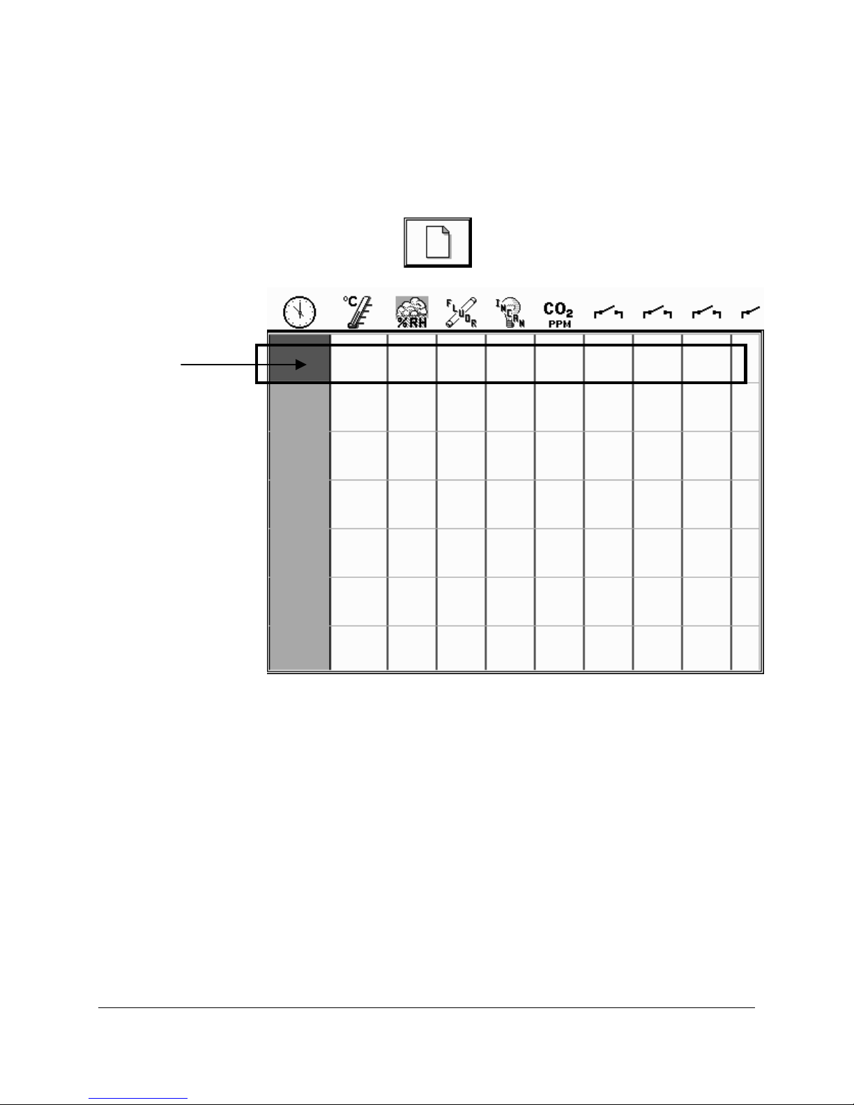
A timeline is a series of control settings scheduled to occur at a specific
time. This represents one row on the Program Table. A program can be
made up of one or many timelines. The duration of a program is a ‘day’ –
a 24-hour period from midnight to 23:59.
Timeline
1. Touch the New
button to display a blank program table.
2. Touch a cell in the Time zone. It will appear darkened.
3. Enter the time on the keypad using the 24-hour format.
4. Touch the OK button to confirm the value entered. After values are
5. Enter the temperature using the keypad. Touch OK.
6. Enter the relative humidity using the keypad. Touch OK.
7. Enter the lighting settings using the keypad. Touch OK. Depending
8. Complete the timeline by entering values in the remaining zones.
9. Complete the program by entering additional timelines as required.
3-8 CMP4030 User Guide
November 2002
entered in a cell, the cell to the right will appear darkened.
Note: If the RH is programmed at 0%, any related dehumidification
equipment will be shut off.
on the lamp types in the chamber, there may be more than one zone
for lighting.
Page 27

Programming the Controller
Tips:
• Start programs at 00:00 and end them at 23:59. Programs following
this format are easier to interpret.
• It is not necessary to enter timelines in chronological order. Touch the
Save button at any time to save and sort the timelines entered.
• To enter the default minimum value in a cell, touch the cell, then
touch OK.
• Timelines can be inserted in the middle of a ramp to control other
zones. Calculating and inserting the condition of the ramping zone is
not necessary.
Changing a
Timeline
Inserting a Timeline 1. Touch a blank cell in the Time column at the bottom of
1. Touch the cell to be changed. The cell will appear
darkened.
2. Enter the changes using the keypad.
3. Touch OK.
the program table.
2. Enter the values using the keypad. Touch OK.
3. Touch the Sort
button. The timeline will display in
the program table in the correct chronological order.
It is not necessary to sort the timelines. Touching either the
Save or Run button will automatically sort them.
Deleting a Timeline 1. Touch the first cell in the timeline to be deleted.
2. Touch the DEL button in the keypad. The contents of all
cells in the timeline will be cleared.
Deleting Individual
Cell Settings
1. Touch the cell for which the setting is to be deleted.
2. Touch the DEL button. The contents of the cell will be
cleared.
3-9
Page 28

Chapter 3: Programming
Verifying a Program
After the timelines have been entered, verify the program by
viewing the zones graphically.
1. Select the zone by touching a cell in the column.
2. Touch the Program Graph
button in the Program
Table toolbar. The Program Graph screen will display the
timelines.
3. Check the program to ensure that all entries are correct.
4. Touch the Exit button to return to the program table.
3-10 CMP4030 User Guide
November 2002
Page 29
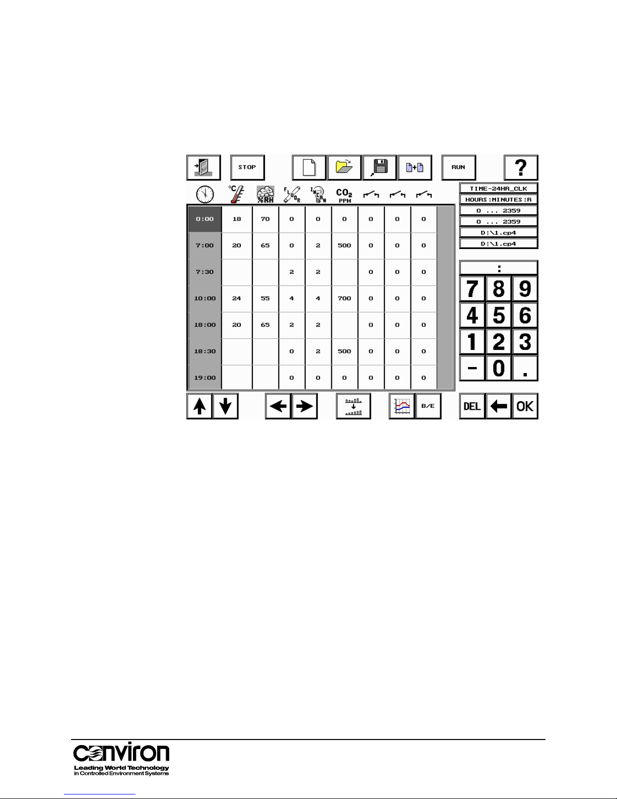
Sample Program 1: Basic Day/Night program
This program is useful to simulate outdoor conditions.
Note: Program red light spectrum for dawn and dusk by turning on two
levels of incandescent lamps and turning off fluorescent lamps.
Temperature
Relative
Humidity
Inserting
Timelines in
a Ramp
• Midnight (0:00) – Temperature in the growth chamber is 18º C
• 7:00 – Temperature has risen to 20º C
• 10:00 – Temperature has risen to 24º C
• 18:00 – Temperature has fallen to 20º and stays constant until 23:59
• Midnight (0:00) – RH is 70%.
• 7:00 – RH has decreased to 65%
• 10:00 – RH has decreased to 55%
• 18:00 – RH has increased to 65% and stays constant until 23:59
Note: Timelines were inserted into this program to control other zones:
• 7:30 – Two levels of fluorescent and incandescent lights come on
• 18:30 – All fluorescent lights shut off, CO
• 19:00 – All incandescent lights shut off, CO
level is set to 500 ppm
2
level is set to 0 ppm
2
Note: Some cells have been left blank so that zones that are ramping
are not affected when the conditions of other zones adjust.
3-11
Page 30
Chapter 3: Programming
Sample Program 2: Programming in Step Mode
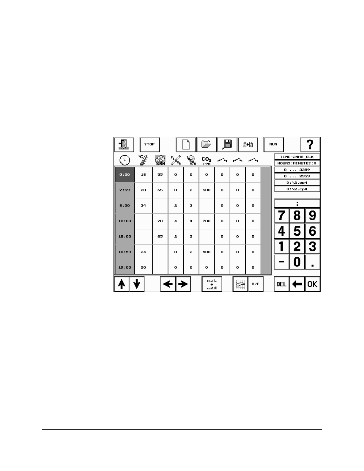
Step programming can be approximated for zones that usually ramp by
inserting timelines to keep the conditions constant until one minute
before the new condition is required.
For example, to have the temperature in the chamber rise four degrees
at 8:00, then fall four degrees at 19:00 (7:00 pm), program as follows.
Note: Programming in step mode is more likely to cause alarms due to
conditions temporarily overshooting alarm limit settings for the zone.
We recommend that the limits be increased if a step program is used.
Note: The psychrometric chart is a valuable tool when writing a
program. To view a copy of the psychrometric chart and for more
information on understanding and using the chart, refer to Appendix D.
3-12 CMP4030 User Guide
November 2002
Page 31
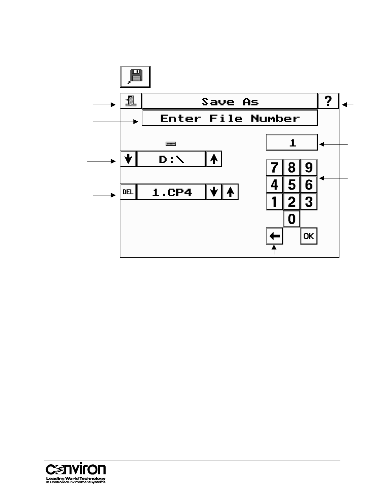
2. Saving Programs
2. Saving Programs
To access the Save Program screen, touch the Save Program
button in the Program toolbar.
Prompt
Display
Drive
Name
Program
Number
Help
Number
Display
Keypad
Save Screen Fields
Exit button
Help button
Prompt Display
Drive Name
Program Number
Number Display
Keypad
Backspace
Backspace
Touch the Exit button to return to the Status screen.
To access on-line help, touch the Help button, then the field or
button for which help is required.
Provides prompts to assist the user.
Displays the currently active drive
• C:\ or D:\ for internal storage (depending on hardware)
• B:\ for a floppy disk drive. The B:\ drive is valid for
controllers with a floppy disk drive.
Touch the arrow buttons to select the drive at the prompt.
Touch the arrow buttons to view existing file numbers on the
selected drive and display them in the number display field.
Displays the same file number as in the Program Number field.
Displays the file number entered when the keypad is used.
Use the keypad to enter a program number.
Touch the Backspace key to clear a digit.
3-13
OK
Touch OK to transfer the entry to the program number field.
Page 32
Chapter 3: Programming
Saving a Program
1. Access the Save Program screen by touching the Save Program
button in the Program toolbar.
2. Follow the prompts in the Prompt Display field.
Drive
• Defaults to the internal memory in the controller (C:\ or D:\)
• To save programs to the floppy disc drive (FDD), use the arrow
keys to select B:\.
Program Number
• To overwrite a program, use the arrow keys to view the list of
existing programs. The program number will appear in the
Program Number field. When the program to be overwritten is
displayed, touch OK to save.
• Rather than rewriting all of the timelines in a program, modify an
existing program and save it as a new program number.
• To save a program as a new program number, use the keypad
to enter a program number. Touch OK to confirm.
• Use caution when assigning a program number. If the program
number already exists, it will be overwritten with the new
program when the OK button is touched.
Deleting a Program
• To clear a digit, touch
.
• By default, the system adds the .CP4 extension to programs.
1. Locate the program number to be deleted using the arrow buttons
in the Program Number field.
2. When the program number appears, touch the DEL button. A
dialogue box will appear for confirmation to delete.
3. Touch Yes to confirm. The program will be deleted.
The delete program function is available in the Save Program or
Chain Program screens.
3-14 CMP4030 User Guide
November 2002
Page 33
3. Chaining Programs – Multi-Day Programming
The Chain Program screen provides the facility to create programs that
can run with different conditions over multiple days.
Chaining is the process of linking programs together so that they run
continuously in sequence. If a program is not chained to itself or to
another program, it will stop running at midnight.
• To run the plant growth area under the same program every day,
chain the program to itself.
• To run the plant growth area under different programs each day,
chain two or more programs together. These are called multi-day
programs. Multi-day programs are limited in size only by the amount
of storage space available in the controller. For additional storage,
use a floppy disk drive.
We recommend that each program have 0:00 and 23:59 timelines and
that the 23:59 timeline match the 0:00 timeline of the next program in
the chain to create a smooth transition from one program to the next.
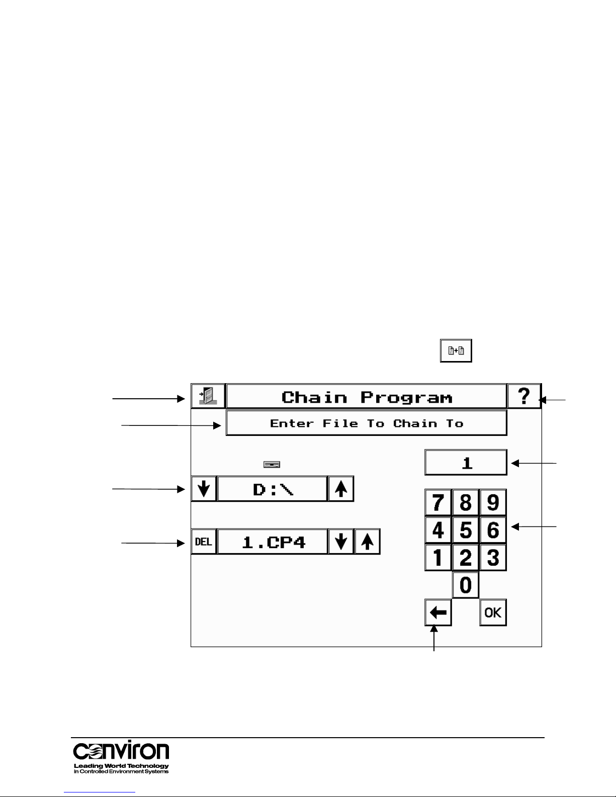
Save Screen Fields
Exit
Prompt
Display
Drive
Name
Program
Number
Access the Chain Program screen by touching the Chain
Program button in the Program toolbar.
Help
Number
Display
Keypad
Backspace
3-15
Page 34

Chapter 3: Programming
Chain Program Screen Fields
Exit button
Help button
Prompt Display
Drive Name
Program Number
Number Display
Keypad
Backspace
OK
Touch the Exit button to return to the Status screen.
To access on-line help, touch the Help button, then the field or
button for which help is required.
Provides prompts to assist the user.
Displays the currently active drive
The B:\ drive is valid for controllers with a floppy disk drive.
Touch the arrow buttons to select the drive at the prompt.
Displays the number of the selected program.
Displays the numbers entered when the keypad is used.
Use the keypad to enter the chain number.
Touch the Backspace key to clear a digit.
Touch OK to transfer the entry to the program number field.
Chaining a Program to Itself
Chaining a program to itself is the most straightforward method of
chaining. If a program is not chained to itself or to another program, it
will stop at midnight.
• C:\ or D:\ for internal storage (depending on hardware)
• B:\ for a floppy disk drive.
1. Ensure that the program to be chained is displayed on the
3-16 CMP4030 User Guide
November 2002
Program Screen.
2. Touch the Chain Program button in the Program toolbar.
The Chain screen will display. The message in the Prompt display
field will read: Enter file to chain to:
3. Enter the program number using the keypad.
4. Touch the OK button. The controller will save the chain.
The Program screen will display when the programs have been
chained. The program table cell Information field for the chained
program path will be updated with the chained program number.
Page 35
Chaining a Program to Itself
Chaining Several Programs
1. Access the Program Screen.
2. Open the first program in the chain.
3. Touch the Chain Program button in the Program toolbar.
The Chain screen will display. The message in the Prompt display
field will read: Enter file to chain to:
4. Enter the second program number using the keypad.
5. Touch OK. The controller will save the chain.
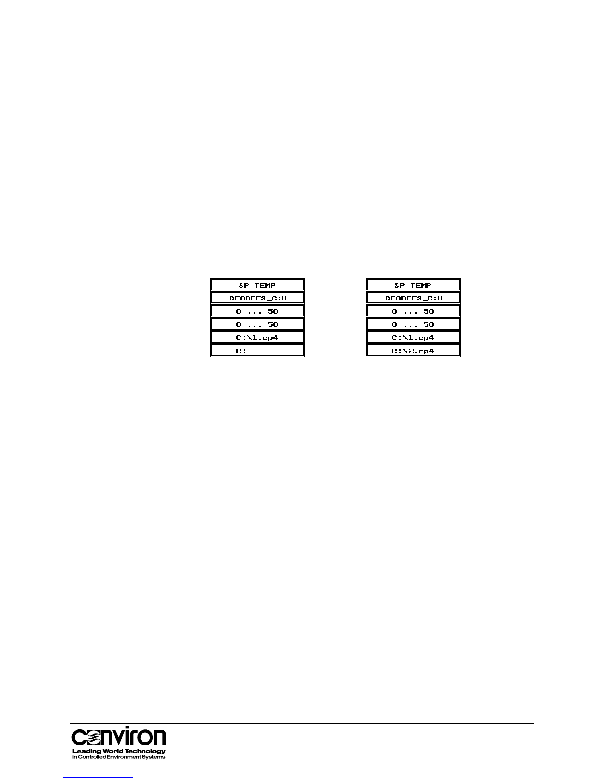
The Program screen will display. The program table cell
Information field will display the program number and extension.
before Chaining after Chaining
6. Open the second program.
7. Touch the Chain Program button in the Program toolbar.
8. Enter the third program number using the keypad.
9. Touch the OK button. The controller will save the chain.
10. Open the third program.
11. Touch the Chain Program button in the Program toolbar.
12. Enter the first program number. This will chain the third
program to the first program to form a loop. This must be done to
run the program continuously.
13. Touch the OK button. The controller will save the chain.
3-17
Page 36
Chapter 3: Programming
4. Running a Chained Program
1. Access the Program screen. Ensure the correct program is
displayed. (Usually the first program in the chain is displayed).
2. Touch the Run button to start the loaded program.
3. Touch the Exit button. The Status screen will appear.
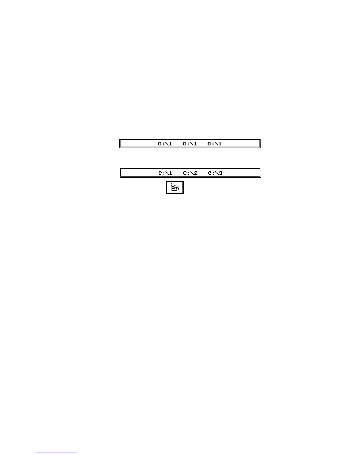
The Program Indicator field will display the location of the program
and the program numbers being run.
• The program below is stored on C:\ and program 1 is chained to
itself.
• The program below is stored on C:\ and programs 1, 2 and 3
have been chained and will be repeated.
• The Program
button in the Status toolbar will flash to
indicate an active program.
Chaining Notes
• Each program sets operating parameters for a 24-hour period
ending at 23:59 (midnight).
• If a program is run without being chained to another
program, it will stop running at midnight.
• For continuous operation, programs must be chained together in
series, with the last program chained back to the first to create a
loop.
• If there is only one program, it must be chained to itself to
allow continuous operation.
• If a program is not in the correct format, when you attempt to
chain the program and error message will appear. Programs
may be incompatible if they were written in different versions of
software.
If the controller is not able to follow the chain:
• an alarm(s) will be displayed and an error message will indicate
why the chain could not be followed
3-18 CMP4030 User Guide
November 2002
• the current program will run continuously
Page 37

Programming Auxiliaries
Auxiliary switches are programmable timers that are used to power
other devices on or off.
Auxiliary switches can be used for:
• time lapse photography
• automatic watering
• gas dosing
• fertilizing
These switches are an optional feature. If the chamber is equipped with
Programming Auxiliaries
Modes of Operation
auxiliaries, the program table will display an auxiliary icon
for
each one, as each auxiliary is a zone of control.
Auxiliary switches have two modes of operation.
• Binary mode
• Event mode
The B/E button works as a toggle switch so as the button is touched, the
Active Cell Unit box will display either B or E. Binary mode – in binary
mode, the auxiliary is either on or off.
To program an auxiliary in Binary mode,
1. Touch the B/E button in the Program Table so the Active Cell Unit
box in the Program Table Unit displays a B.
2. Touch the cell in which you want to enter information.
3. Using the keypad, enter either 0 or 1
0 – Off during the period covered by the timeline
1 – On during the period covered by the timeline
The controller displays a + symbol to represent each ‘1’ entered.
Event mode – in Event mode, the auxiliary switch can be programmed
to turn on for a defined period after the start of the timeline. Entries are
made in seconds and the value can range from 0 to 999.
To program an auxiliary in event mode,
1. Touch the B/E button in the Program Table so the Active Cell
2. Touch the cell in which you want to enter information.
3. Enter the number of seconds that the auxiliary should come on
3-19
Unit box in the Program Table Unit displays an E.
after the start of the timeline.
Note: All timelines in an auxiliary zone must be in the same
mode. Different auxiliary zones can operate in different modes.
Page 38
Chapter 3: Programming
Auxiliary Program Example
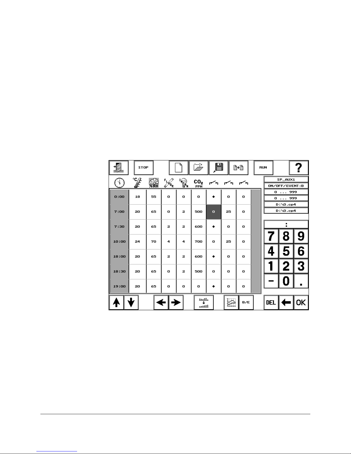
The graph below is an example of a program using auxiliaries.
The Program provides the following information:
• there are three auxiliaries
• the first auxiliary zone is in binary mode. The Active Cell Units
• the second auxiliary zone is in event mode. This is evident
• the third auxiliary is not used.
• there is one program and it is chained to itself.
field is displaying a B and plus (+) signs are displayed.
because some of the settings are greater than 1.
Auxiliary 1 – Binary mode
Auxiliary 2 – Event mode
• Is on for 25 seconds at 7:00 am
• Is on for 25 seconds at 10:00 am
3-20 CMP4030 User Guide
November 2002
• Is on from 7:30 until 10:00 am.
• Is on from 18:00 (6:00 pm) until 18:30 (6:30 pm)
• Is on from 19:00 (7:00 pm) until 7:00 am.
Page 39

Chapter 4: Alarm Management
Setting and managing Alarms are essential parts of an experiment. Alarms monitor experiment
conditions and provide notification when a condition changes beyond the set limits. The Alarm
facility provides:
• the ability to program Alarms to protect the experiment and research.
• error messages and reporting management.
• the user with ample time to systematically shut down the chamber so that an error
affects the research as little as possible.
4-1
Page 40
Chapter 4: Alarm Management
y
A
The Alarm Screen
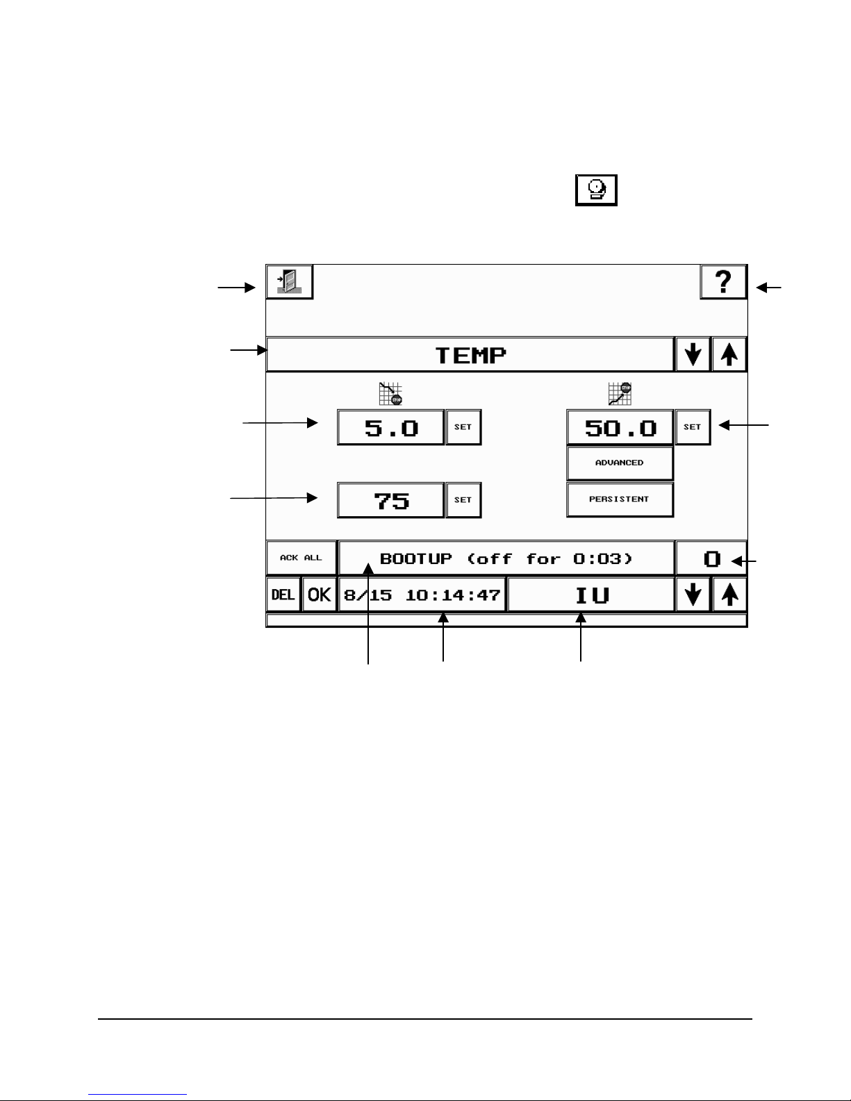
To access the Alarm screen, touch the Alarm
Status screen toolbar.
Exit
Alarm
Label
button in the
Help
High
Alarm
Limit
Alarm
Sequence
Number
Low Alarm
Limit
Alarm
Priorit
Alarm
Message
Display
larm Date
and Time
Alarm
Status
4-2 CMP4030 User Guide
November 2002
Page 41

Alarm Screen Fields
Exit button
From the Alarm screen, touch the Exit button to return to the
Status screen.
Help button
To access on-line help, touch the Help button, then the field or
button for which help is required.
Alarm Label
This field displays the current Alarm Label. Use the arrows to
scroll through the list of labels.
Low Alarm Limit
This field displays the low Alarm limit for the current Alarm
configuration. Touch the Set button to display a keypad and
enter a value.
High Alarm Limit
This field displays the high Alarm limit for the current Alarm
configuration. Touch the Set button to display a keypad and
enter a value.
Alarm Priority
This field displays the Alarm Priority. Touch the Set button to
display a keypad and enter a value.
Advanced button
Touch this button to view all possible alarm labels in the Alarm
Label field. Ordinarily, only commonly used labels are displayed.
Persistent button
Touch this button to attach the Persistent feature to an Alarm.
Persistent alarms cannot be turned off until the condition is
cleared.
Acknowledge All
Touch the Ack All button to acknowledge all active Alarms.
(Ack All) button
Alarm Sequence
Number field
Delete (Del) button
This field displays the sequence of the alarm messages, from
0 to 99.
The Delete button deletes the currently displayed Alarm.
If the alarm condition is still active the alarm will recur
immediately.
Alarm Status field
Alarm Message
Display
This field displays the current status of an Alarm
This field displays alarm messages. Touch the up and down
arrows to scroll through the Alarm messages.
See Appendix B: Alarm Messages for more information.
OK button
Touch OK to acknowledge the currently displayed Alarm.
4-3
Page 42
Chapter 4: Alarm Management
Alarm Options
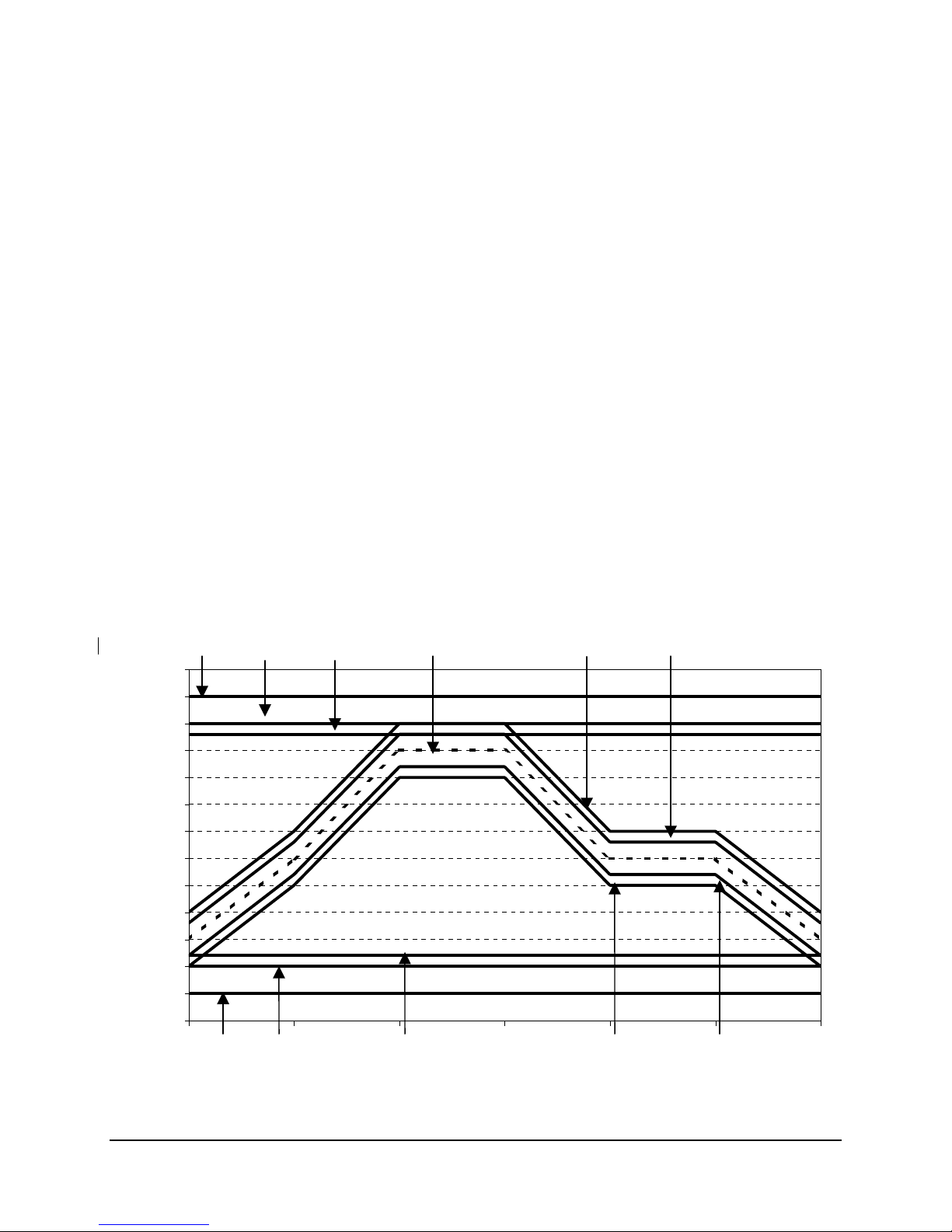
Two types of program alarm options are available, Deviation and Tracking.
• Deviation alarms set upper and lower limits that apply to the entire program.
• Tracking alarms are based on the set point at any particular time in the program,
including during ramping. The user sets the minimum and maximum variance
from set point.
• Both alarms include a preliminary warning and shutdown settings.
Priority determines what action is taken when an alarm limit is reached, for example
raising an alarm message, shutting off the chamber, initiating an auto-dialer.
The chart below displays various temperature alarms and possible settings.
ITSO = Independent Temperature Shut Off
SDTD = Shut Down on Temperature Deviation
TEMP = Temperature warning alarm
Track SD = Shut Down on Tracking alarm
High
ITSO
55
50
45
40
35
30
25
20
Temperature
15
10
5
0
-5
-10
Low
ITSO
High
SDTD
Low
SDTD
High
TEMP
ACTUAL
TEMPERATURE
Low
TEMP
Time
High
Track SD
Low Track
SD
High Track
Warn
Low Track
Warn
4-4 CMP4030 User Guide
November 2002
Page 43

Programming an Alarm
1. Access the Alarm screen.
2. Select the Alarm to be programmed. Use the arrow keys in the
Alarm Label field to cycle through the list.
For a complete list of labels, refer to on-line Help or see
Appendix A: Labels.
3. Set the Low Alarm limit. Touch the Set button in the Low Alarm field
to display a keypad and enter the low limit.
• The value entered cannot be lower than the factory set minimum.
4. Set the High Alarm limit. Touch the Set button in the High Alarm
field to display a keypad and enter the high limit.
• The value entered cannot be higher than the factory set
maximum.
Note:
New with Conviron’s Version 6.0 software, the values entered in the
limit fields are saved so that this information does not have to be
re-entered when the system is re-booted.
Complete steps 5 and 6 if a setting other than the default is required.
5. Set the Alarm Priority. Touch the Set button in the Alarm Priority
field to display a keypad and enter the high limit. Refer to the Alarm
Priority Values chart below.
• The value entered must be between 1 and 99. The chart below
lists the urgency associated to each block of numbers.
• See Appendix B: Alarm Messages for default Alarm priorities.
Alarm Priority Values
Number
1 – 20
21 – 40
41 – 60
61 – 80
81 – 99
Urgency
Very high
High
Medium
Low
None
Indicator device(s) activated
Alarm button, lamp, buzzer, auto dialer
Alarm button, lamp, buzzer
Alarm button, lamp
Alarm button
None
6. Touch the Persistent button to attach this feature to the Alarm.
Typically, this feature is used on more critical components of an
experiment because the alarm can only be cleared manually (as opposed
to other alarms that will clear automatically when the condition causing the
alarm no longer exists).
4-5
Page 44
Chapter 4: Alarm Management
Alarm Indicators
An Alarm indicator notifies the user that a problem exists.
Two standard Alarm indicators are built into every Conviron growth chamber. In
addition to these, there are optional Alarms, which can be built into the chamber.
Standard Alarm Indicators
Optional Alarm Indicators
• An Alarm button
will flash on the Status
toolbar of the controller when there is an active,
unacknowledged Alarm. The button will continue
to flash until the Alarm is acknowledged.
• A buzzer will sound as the audible equivalent of
the flashing Alarm on the CMP4030 controller or
as an indication that the ITSO (independent
temperature shut-off) has shut off the chamber.
For more information on the ITSO, refer to page 8
of this chapter.
• An external Alarm Indicator lamp, which will light
up when an Alarm is active.
• A Chamber Alarm Contact (CAC) relay. The CAC
is connected to another device or system selected
by the user which will indicate an active Alarm.
In most cases, the CAC is connected to an
existing internal building security system or an
autodialer that will dial a pre-programmed
number and leave a message to alert the
operator that an Alarm exists.
4-6 CMP4030 User Guide
November 2002
Page 45

Responding to an Alarm
An Alarm provides warning that a problem exists in the
program.
1. Access the Alarm screen by touching the Alarm
button in the Status toolbar.
2. Read the Alarm message. If you do not understand the
message, refer to Appendix B: Alarm Messages.
3. Record the time that the message was issued.
4. Acknowledge the Alarm. When the Alarm is
acknowledged, the Alarm Status will be updated.
• To acknowledge the current Alarm, touch the OK
button. The system will set the status of the Alarm
to inactive.
• To acknowledge all Alarms, touch the Ack All
button. The system will set the status of the Alarms
to inactive.
• All Alarms can be deleted. However, active Alarms
immediately recur.
• If the Persistent feature has been added to the
Alarm, the condition must be corrected before the
status of the Alarm can be acknowledged to change
the status to Inactive.
Alarm Status Field Codes
AU Active, Unacknowledged. The Alarm is active and
acknowledged.
AA Active, Acknowledged. The Alarm has been
acknowledged but the condition that caused the Alarm
has not been corrected.
IU Inactive, Unacknowledged. The condition that caused
the Alarm has been corrected, but the Alarm has not
been acknowledged.
IA Inactive, Acknowledged. The Alarm message has been
acknowledged and the condition that caused the Alarm
has been corrected.
Take corrective action.
• Adjust Alarm settings if necessary.
• Repair the fault.
• Shut down and restart the chamber.
4-7
Page 46

Chapter 4: Alarm Management
Independent Temperature Shut-Off (ITSO)
Technical Support
The ITSO is a fail-safe protector that shuts the chamber off if its
limits are exceeded. The ITSO relies on its own sensor so that it
operates completely independently in case of control system
failure.
The factory default settings are 5° beyond the chamber
operating range. If settings are changed, they should be no less
than 10° outside the range of the programmed high and low
temperature settings for the experiment.
The operation of the ITSO is not directly reflected on the Alarm
screen of the controller. However, if the ITSO shuts off the
chamber, the resulting loss of power to the outputs will trigger a
‘chamber off’ Alarm.
ITSO controls are located inside the control panel where
there is live high voltage. Service personnel under the
instruction of Conviron Technical Support should set
parameters. Contact Conviron Customer Care for more
information.
For technical support, contact your local technicians.
Conviron Customer Care
When contacting Conviron Customer Care, please provide the
chamber serial number, which is located on the rating plate on
the side of the chamber.
Toll free in North America
Local telephone
Fax
E-mail
Web address
1-800-363-6451
1-204-786-6451
1-204-783-7736
www.conviron.com
4-8 CMP4030 User Guide
November 2002
Page 47

Chapter 5: Login and Security Procedures
CMP4030 Security Procedures
The CMP4030 is shipped with security features turned off. This enables the user to start the
chamber and become familiar with the chamber controls without having to enter a password.
We recommend that a security administrator be assigned to administer user login authority and
that security features are added as soon as possible.
This chapter describes:
• The Login screen
• Login procedures
• How to change your password
• How to assign security levels
• Security Administrator procedures
5-1
Page 48
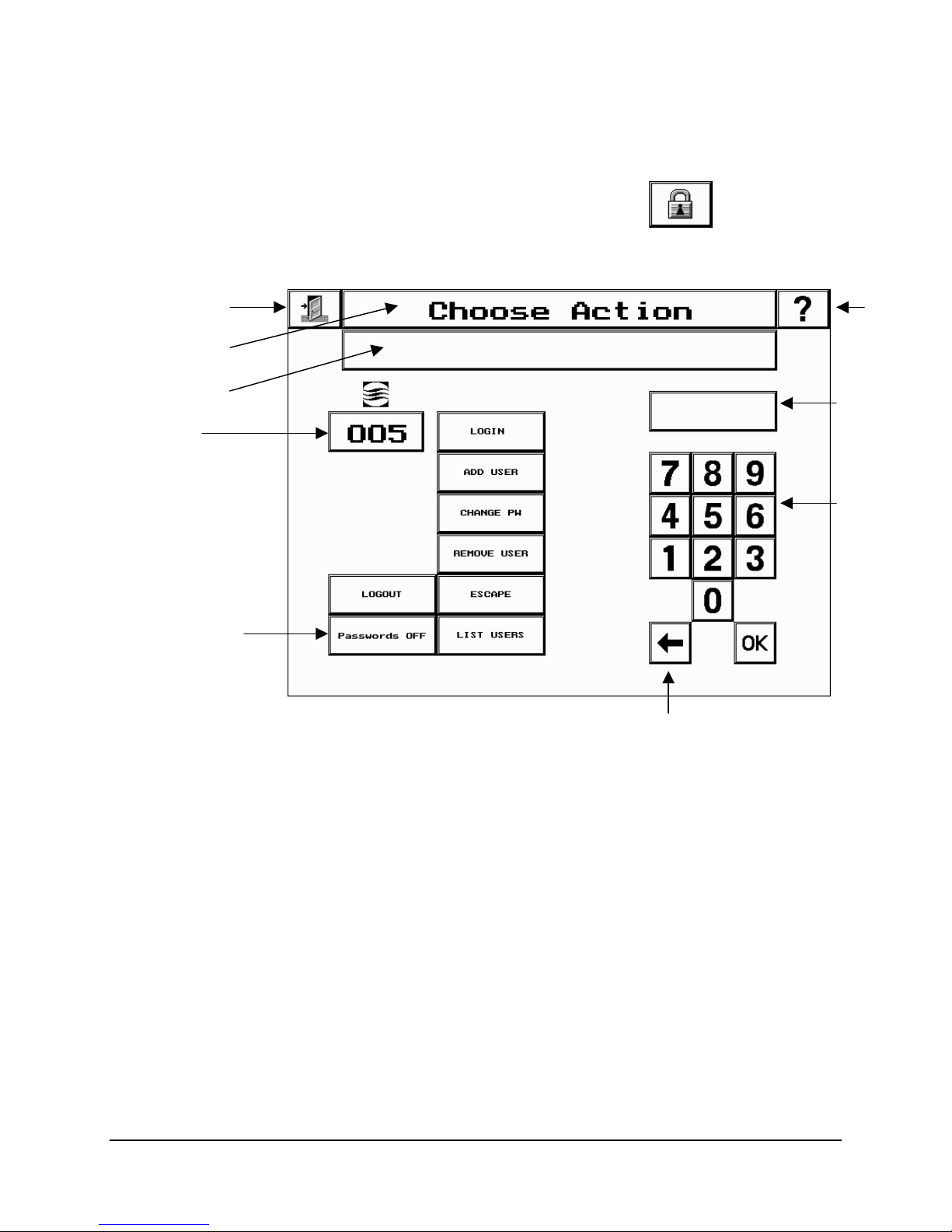
Chapter 5: Login and Security Procedures
play
The Login Screen
Function Display
Prompt Display
Chamber ID
Exit
To access the Login screen, touch the Security
Status toolbar.
button in the
Help
Number
Dis
Keypad
Security Lock
Backspace
5-2 CMP4030 User Guide
November 2002
Page 49

Login Screen Fields
Login Screen Fields
Exit button
Touch the Exit button to close the Login screen and to return to
the Status screen.
Help button
Function Display
Prompt Display
Chamber ID
Login button
Add User button
Change Password
(PW) button
Remove user
button
To access on-line help, touch the Help button, then the field or
button for which help is required.
This field displays the function selected.
Provides prompts to assist the user.
This field displays the chamber ID. The Chamber ID identifies the
chamber to the CCS if installed on a network.
Touch this button to start the login process.
Touch this button to add a new user to the system. This feature is
used most often by the security administrator.
Touch this button to change a password.
Touch this button to remove a user from the system.
Logout
Escape
Security Lock
Touch this button to log out the current user ID.
Touch this button to stop the current procedure.
A binary button used to turn security on or off. Once security is
on, only a user with the correct security level can turn if off.
List Users
Touch this button to view a current list of users that have access
to the system.
Keypad
As numbers are entered using the keypad, they will display in the
Number Display field.
Backspace button
OK
Touch the Backspace key to clear a digit.
Touch OK after correctly entering a number using the keypad.
5-3
Page 50

Chapter 5: Login and Security Procedures
Security Screen Procedures
Logging In
If the controller security lock is on, follow the login procedures below.
Note: logging in may also be done at the Central Control System.
1. Touch the Login button.
The Function Display field will read Login
The Prompt Display field will read Enter User ID
2. Enter your User ID using the keypad. Touch OK.
3. Enter your Password. Touch OK.
The Function Display field will read Login successful and you will
have access to the CMP4030 screens associated with your security
level.
If the Login screen reads User not found or Password incorrect,
contact your Security Administrator.
If this is your first time logging into the controller, change your
password now.
Changing your Password
For security reasons, it is recommended that you change your password
frequently. Your Security Administrator will assign your first (temporary)
password.
1. Touch the Change PW button on the Login Screen.
Follow the instructions that appear in the Prompt display field.
• Passwords can be between 1 and 8 characters long.
• All characters must be numeric.
2. Touch the Exit button to return to the Status screen.
Logging Out
1. Touch the Logout button on the Security screen. The Status screen
will appear and the controller will display a Local Logout message.
Note: After five minutes of inactivity, the system will automatically log
out all users and return to the Status screen.
5-4 CMP4030 User Guide
November 2002
Page 51

Security Levels and Functions
Security
Provides Access to:
Level
10
Status screen
Trendgraph screen
Security screen excluding: adding or removing users with
a security level greater than 10.
Alarm screen in view only mode, which allows you to
cycle through the labels and alarm messages but not to
change settings or delete messages.
20
Program screen
Program Graphing screen
Deleting alarms
Changing alarm settings, priority and persistence
Options screen, excluding setting chamber ID, which
requires security level 30.
30
Adding and removing users with security levels of 30 or
lower.
Setting startup delay and chamber ID
40
All screens and features
Diagnostics screen
Security lock OFF
Adding or removing users with a security level of 40 or
lower.
Note: If you attempt to access a screen for which you do not have
authority, the screen prompt field will display the message
Access Denied.
5-5
Page 52

Chapter 5: Login and Security Procedures
Activating Security
Security
Administrator Set-up
The security administrator is responsible for initiating controller
security.
The security lock default setting is
PASSWORDS OFF. In this
mode:
• The
• The
LOGIN, LOGOUT, and LIST USERS buttons function
ADD USER, CHANGE PW, REMOVE USER, and ESCAPE
buttons do not function
• User ID’s cannot be added until
1. Touch the Passwords button to toggle to
PASSWORDS ON is selected.
PASSWORDS ON.
Note: When the screen displays Passwords ON, a password
is required. Users without a password have a security level
of 10.
2. Touch the Login button. Follow the prompts to enter User
ID 40 and password 0.
Note: After entering numbers using the keypad, touch the
OK button.
3. Touch the Add User button and follow the prompts to
create an ID, between 1–8 digits, for the security
administrator. Enter 40 as the required security level.
The Security screen will display a message indicating that
the User ID has been added. The Security screen will return
to Login mode.
4. Touch the Change PW button.
• At the prompt, enter the security administrator ID created
in step 3.
• At the enter password prompt, touch OK.
• At the prompt, enter a new password (between 1– 8
digits)
• At the prompt, re-enter the new password. The prompt
will display a message that the password was changed.
Repeat steps 3 and 4 to add other users. Remember to set
the appropriate security level.
For reference, maintain a paper copy of the User ID’s and
passwords. This information is restricted and should be stored in
a secure place.
5-6 CMP4030 User Guide
November 2002
Page 53

5. For added security, change or remove the default User ID
40. Use one of the following methods.
I. Touch the Change PW button.
Enter 0 when prompted for the current password.
Change the password for User ID 40 to a number
other than 0.
II. Touch the Remove User button.
Enter 40 when prompted for the User ID. The prompt
will confirm the User was removed.
Default User IDs
Default User IDs are set at Conviron. This allows the Security
Administrators to first, activate security and then set up temporary User
IDs and passwords for themselves and for other users.
After signing on once with a default User ID and password, the user
should immediately change his or her User ID and password.
IDs and passwords can consist of numeric characters only.
User ID Security level Password
10 10 0
20 20 0
30 30 0
40 40 0
5-7
Page 54

Chapter 6: Setting Options and Logging Data
Setting options is a critical part of control system operation as the experiment data recorded is
dependent on the type of options selected.
The logging feature provides a record of chamber conditions throughout the experiment.
The Options screen allows the user to:
• enter or adjust system settings
• set logging data options
• set the chamber ID
6-1
Page 55
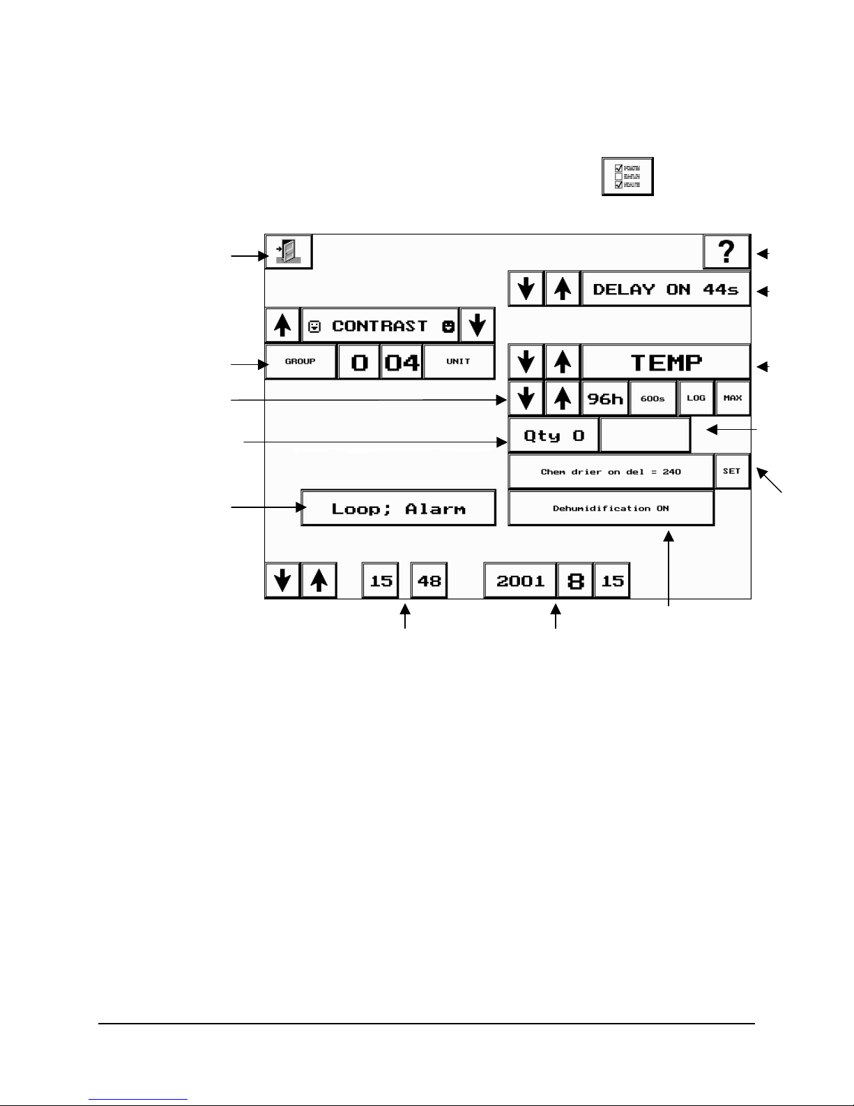
Chapter 6: Setting Options and Logging Data
y
The Options Screen
Exit
To access the Options screen, touch the Options
Status toolbar.
button in the
Help
Start
Dela
Chamber
ID
Logging Capacity
and Frequency
Quantity
Log
Function
Options Screen Fields
Help button
Exit button
Time
Date
Parameters for
Dehumidification
Touch the Exit button to return to the Status screen.
To access on-line help, touch the Help button, then the field or
button for which help is required.
Label
Time
Remaining
Parameters
for Chemical
Drier and
Defrost
Contrast and
Brightness
Chamber ID
6-2 CMP4030 User Guide
November 2002
Location of the Brightness controls depends on controller model.
The V1 and V2 hardware (displayed in the diagram on page 2),
do not have outboard controls so contrast must be set using the
on-screen control. Touch the arrows to adjust contrast.
V3 and later hardware is equipped with outboard contrast and
brightness controls so this feature does not appear on screen.
Ambient temperature can affect the brightness of the controller
screen. Use the brightness controls to make adjustments.
The Chamber ID identifies the chamber to the Central Control
Page 56

Options Screen Fields
System (CCS). The ID is comprised of Group and Unit numbers.
Group number – may be used to identify a group of chambers by
a common trait such as room, floor or owner.
Unit number – indicates the number of the individual chamber in
the group.
Log Function
button
This button is used to set the log function to one of four choices.
The field displays the Log Function selected.
The log function determines what happens when internal memory
is full.
Start Delay
This field shows the delay, in seconds, of startup for the chamber.
A start delay is recommended to avoid a drain on the electrical
power source.
Label
This field displays the label for which logging options are currently
being set.
Logging Capacity
and Frequency
The first field (to the right of the arrows), displays logging capacity
in hours. This is the number of hours of data that can be logged
to the memory in the controller. It varies inversely with the logging
frequency.
The second field displays logging frequency in seconds. This is
the number of seconds between each recording of the data. It
varies inversely with the logging capacity.
Quantity
Chemical Drier
and Defrost
The Qty field shows the number of items selected to log.
The Chemical Drier parameter button is used to make
adjustments to the additive humidity and dehumidification.
The Defrost parameter button is used to make adjustments in the
defrost cycle.
Dehumidification
The Dehumidification On/Off button allows this feature to be
turned off when it is not required.
Time Remaining
The Time Remaining field displays in hours, the amount of
logging time left on the floppy disk. This field is valid only if the
unit is equipped with an FDD.
Time
Date
Displays the time in a 24-hour format.
Displays the date in year-month-day format.
Note: The date, time and logging options cannot be changed if you have a program running. To
make modifications, stop the program from the Program screen and make the necessary
changes.
6-3
Page 57

Chapter 6: Setting Options and Logging Data
System Settings
This section provides instruction on programming system settings.
Generally, it is not necessary to change the information in the system
settings fields with each experiment.
1. Enter the chamber ID. Touch the Group and Unit buttons to set the
ID.
Note: The chamber ID identifies the chamber to the CCS. If the
chamber is not connected to a CCS, disregard this setting.
• The default ID of 100 must be changed.
• The Group number can be set from 0 – 7.
• The Group number can be used to identify a series of chambers
with some commonality. For instance, the same floor, same user,
etc.
• The Unit number can be set from 1 – 30.
• The Unit number can be used to identify the individual chamber.
• The chamber ID is displayed as a read-only field on the Status and
Security screens
Reboot the controller after completing this procedure.
2. Set the Start Delay. Use the arrows to set the number of seconds
for start delay.
• Chambers can be set to turn on at staggered times to avoid a
drain on the building power supply. It is recommended that
multiple start up delays be set in 10-second intervals.
Chemical Drier/Defrost and Dehumidification Settings
If your chamber is equipped with chemical drier, defrost or
dehumidification features, the buttons to adjust these parameters will
appear on the Options screen.
Consult Conviron Customer Care before adjusting these
settings.
6-4 CMP4030 User Guide
November 2002
Page 58

Setting the Chemical Drier
Options Screen Fields
Setting
Dehumidification
Dehumidification
ON/OFF
1. Touch the Parameter button to cycle through the parameter list.
There are two adjustable parameters for the chemical drier operation:
i. Chem drier on delay – sets the delay time before the
drier comes on when %RH is greater than the set limit.
ii. Chem drier off delay – sets the delay time before the
drier shuts off when %RH is less than the set limit.
2. Touch the Set button. The keypad will appear.
3. Enter the chemical drier settings using the keypad.
4. Touch the OK button to confirm the value entered.
5. Touch the Exit button to return to the Options screen.
The Dehumidification On/Off button allows this feature to be turned off
when it is not required.
Touch the Dehumidification button to toggle between Dehumidification
ON and Dehumidification OFF.
Setting Defrost
• The additive humidity function will still operate if the
Dehumidification feature is turned off. If the relative humidity is
greater than the set limit, it will eventually settle to ambient
condition, adjusted for the temperature variance between ambient
and chamber.
• Turning the Dehumidification feature off saves on energy costs
and wear on the components.
Defrost parameters should be set by service personnel under the
instruction of Conviron Technical Support. Contact Conviron Customer
Care for more information.
6-5
Page 59

Chapter 6: Setting Options and Logging Data
Setting Logging Options
This section provides instruction on setting logging options. Generally,
information that exists in the logging options fields is changed with each
experiment.
1. Access the Options screen.
2. Select the Label to be logged. Use the arrow keys in the Alarm
Label field to cycle through the list.
• When a label is selected for data logging,
- the Log button on the Option screen will darken.
- the Options button on the Status screen will flash.
3. Set the Logging Capacity and Frequency. Use the arrow keys to
cycle through the available logging options.
• The first field (logging capacity) displays the capacity, in hours, of
internal memory.
• The second field (logging frequency) displays the interval, in
seconds, between each data recording.
• As Labels to be logged are added, the capacity will decrease.
• As the logging frequency increases, the logging capacity
decreases.
• The controller automatically samples data every ½ second and
records the average of these samples according to the Frequency
setting.
• The Trendgraph screen displays logged data only.
4. Touch the LOG button to enable the Logging function. If the LOG
button is not touched, data for the label will not be recorded.
5. Touch the MAX button to log the maximum value in the logging
period rather than the average value.
Note: The Qty (Quantity) field displays the number of items selected
to log. As the number of items changes, the logging frequency and
capacity will change.
6. Set the Log function to specify system response when internal
memory is full. There are four available settings.
Note: Chambers equipped with an FDD or connected to a CCS,
automatically download data to those devices. Setting the appropriate
log function is important should one of these devices fail.
6-6 CMP4030 User Guide
November 2002
Settings System Response
Page 60

Options Screen Fields
1. No Loop, Alarm
(Default Setting)
2. Loop, Alarm
Stop logging to prevent overwriting of data
and raise an alarm on the Alarm screen.
Overwrite the oldest data in internal
memory and raise an alarm on the Alarm
screen.
3. No Loop, No alarm Stop logging when internal memory is full
but do not raise an alarm.
4. Loop, No alarm Overwrite the oldest data in internal
memory but do not raise an alarm.
Storing Logged Data
Logged data is automatically stored into the internal memory (storage) in
the controller. Regardless of additional storage options, logged data is
stored in this facility first. In addition to the internal memory area, your
controller may be equipped with the options of logging to a CCS or a
floppy disk.
• If the controllers are networked to a CCS, data is logged to the CCS.
• If the controller has a floppy disk drive, data is logged to the disk in
the B:\ drive.
• To export data to other software, the chamber must be equipped with
a floppy disk drive or be connected to a CCS.
• If the chamber is not equipped with a CCS or a floppy disk drive, the
data will be logged to the internal memory only and can only be
viewed on the Trendgraph screen.
6-7
Page 61
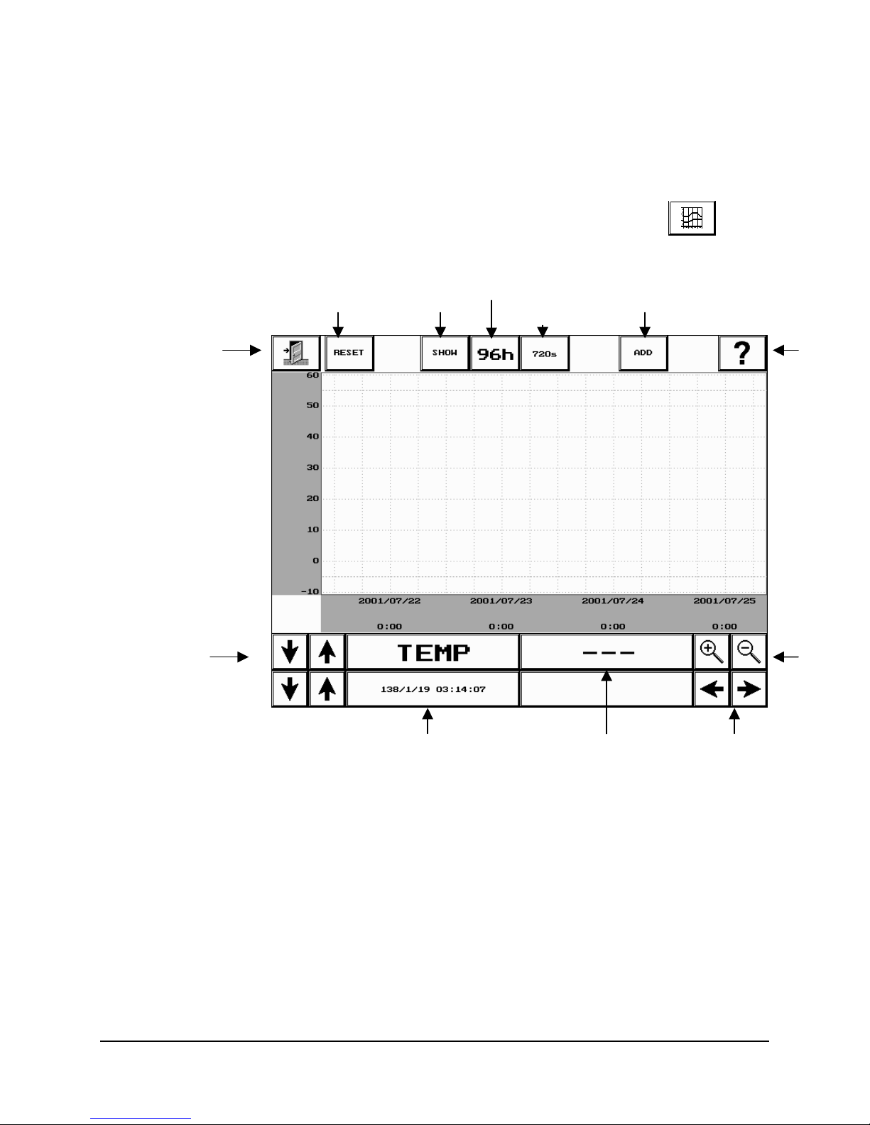
Chapter 6: Setting Options and Logging Data
The Trendgraph Screen
The Trendgraph screen provides a graphical view of logged data.
To access the Trendgraph screen, touch the Trendgraph
in the Status toolbar.
Show Reset Add
Logging
Capacity
Logging
Frequency
button
Help Exit
Label
Date and Time
Label Value
Scroll Arrows
Trendgraph Screen Fields
Exit button
Reset
Show
6-8 CMP4030 User Guide
November 2002
Touch the Exit button to return to the Status screen.
Touch the Reset button to clear the screen
Touch the Show button to display a graph of the data for the
selected label.
Zoom
Page 62

Trendgraph Screen Fields
Logging Capacity
The Logging Capacity field displays the number of hours of logged
data that can be stored in the internal memory of the controller.
If logged data exists for the time period, it will be displayed on the
Trendgraph screen and the X-axis will be scaled.
Logging
Frequency
Add
The Logging Frequency field displays the frequency that was set in
the Options screen.
Touch the Add button to plot the data from another label on the
displayed graph.
Help button
To access on-line help, touch the Help button, then the field or
button for which help is required.
Label
Label Value
This field displays the Label of the most recently displayed graph.
This field displays the value for the date and time.
• When there is no value, the field will display a row of dashes. (-
• If the number of dashes displayed is continuously changing,
- -).
this indicates that the controller is currently tracking logged
data.
Zoom
Date and Time
Scroll Arrows
These buttons provide zoom in and zoom out features.
This field displays the date and time for the Label value displayed.
These buttons provide a scroll feature to view the entire graph.
6-9
Page 63

Chapter 6: Setting Options and Logging Data
Creating a Graph
The Trendgraph screen displays data that is logged in the internal memory of the
controller. The data is logged according to the settings in the capacity and frequency
fields of the Options screen.
Data that is stored to either an FDD or to the CCS can be viewed separately on a PC
using common applications such as Excel or Lotus.
• If your controllers are networked to a CCS, data is logged to the CCS.
• If your controller has a floppy disk drive, data is logged to the disk in the B:\ drive.
• If you have neither of these, data is logged only to the internal memory in the
controller.
1. Select a Label by touching the up and down arrows.
2. Touch the Show button to display the graph on screen. The
hourglass symbol will appear and the Label Value screen will display
moving dashes while the graph is being plotted.
Note: Graphing does not disturb the operations of the chamber.
Displaying Multiple Labels
The Trendgraph screen has the ability to plot the logged data from
several or all logged labels on one screen.
Touch the Add button to plot the data of another logged label on the
graph.
• The scale of the y-axis changes to the scale of the most recently
selected label.
Stop Graphing
To stop graphing, touch the graph area of the screen once.
6-10 CMP4030 User Guide
November 2002
Page 64

Chapter 7: Maintenance and Troubleshooting
This chapter describes:
• how to inspect and clean control panel components
• how to check operating histories using the Diagnostics screen
• how to clear the static Ram (SRAM) and re-calibrate the touch screen
• how to replace the external controller battery
• controller software updates
For more information on troubleshooting with alarms, see Chapter 4, Alarm Management.
1
Page 65

Chapter 7: Maintenance and Troubleshooting
Inspecting and Cleaning Control Panel Components
Inspecting Cooling Fans
Cleaning the Air Intake Filter
Most Conviron chambers are equipped with cooling fans,
primarily for the control panel or lighting ballasts.
Regular inspection of the fans is crucial to maintaining reliability
and avoiding equipment damage.
Replace non-working fans immediately.
Most Conviron control panels are equipped with a fresh air intake
to cool the control panel components. The intake grill and filter
prevent dust and other debris from getting inside the control
panel.
Clean the air intake filter regularly to ensure adequate cooling of
the components.
To clean the filter:
1. Remove the air intake grill mounting screws. Remove the
grill and filter from the control panel.
• It is safe to leave the chamber running while the grill
and filter are being cleaned.
2. Wash the filter with a mild soap solution. Rinse with clean
water.
3. Dry the air intake filter thoroughly.
Remount the air intake grill and filter using the mounting screws.
Cleaning the BUS and Other Cable Connections
Cables connect the components of the Control system.
The connections may become dirty and may loosen with
equipment vibration or thermal expansion.
To avoid control system failure, we recommend that cleaning and
reseating these connections be performed as routine
maintenance between experiments.
Qualified service personnel using Electrostatic Discharge
precautions must perform this work. The procedure is
outlined in the CMP4030 Service Manual.
7-2 CMP4030 User Guide
November 2002
Page 66
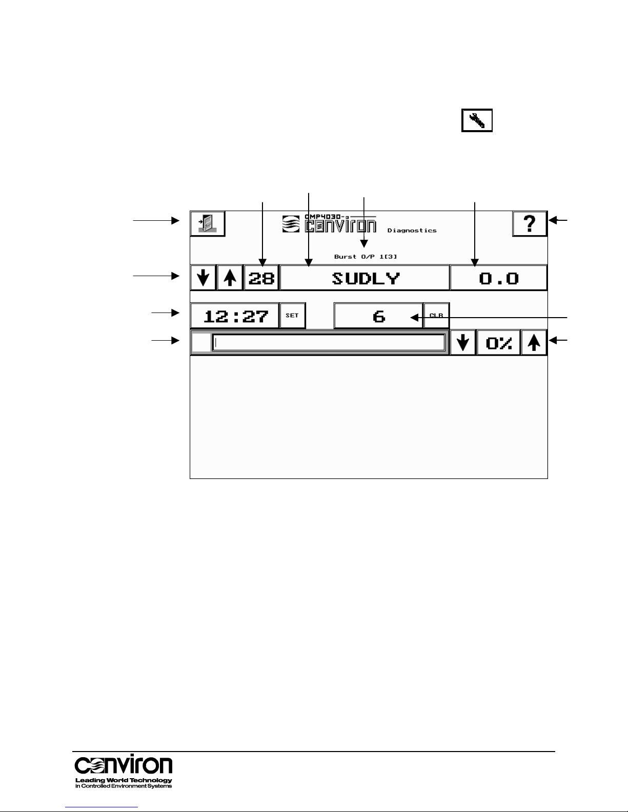
r
g
The Diagnostic Screen
To access the Diagnostic screen touch the Diagnostic
the Status toolbar.
Sequence
Numbe
Controller Software Updates
button in
Label Current
Physical Output
Location
Settin
Exit
Label
Fields
Operating
Hours
Power Bar
Help
Cycles
Power
Setting
7-3
Page 67

Chapter 7: Maintenance and Troubleshooting
Diagnostic Screen Fields
Exit
The Diagnostics screen is generally intended for use by qualified service personnel to
aid in the diagnosis of equipment problems.
In addition to this, the Diagnostics screen also displays operating histories for each
output. The operating histories are particularly useful for monitoring the ‘age’ of the
lamps in order to schedule replacement before lighting intensity decreases too much
or they fail completely.
Touch the Exit button to return to the Status screen.
Help
To access on-line help, touch the Help button, then the field or
button for which help is required.
Label Fields
Sequence
Number
Displays the output or input label sequence number.
Label
Displays the output or input label. This label matches the label on
both the chamber schematics and the physical outputs.
Physical Output
Location
Displays the physical location (board #, channel #) of the output
or input.
Current Setting
Displays the current condition of the input or output.
Service History Fields: Operating Hours and Cycles are service history fields. They display the
service history for output labels only.
Operating Hours
Displays the number of output operating hours.
Touch the SET button to display a keypad to change the
operating hours
.
Cycles
Displays the number of completed output cycles.
Touch the CLR button to clear the service history for the output
Power Bar
The Power Bar displays the current output voltage relative to
maximum output voltage.
7-4 CMP4030 User Guide
November 2002
The voltage can be adjusted to perform diagnostics.
Page 68
Controller Software Updates
Clearing SRAM Memory and Recalibrating the Touch Screen
Read these directions completely before clearing the SRAM or
recalibrating the touch screen.
This procedure is not equipped with an Escape feature. Once
started, it must be completed.
Important:
If you make a mistake,
• wait three (3) minutes before turning off the controller.
• wait another 10 seconds and turn the controller on again.
1. Turn the controller disconnect switch to OFF, wait at
least 1 minute and turn the switch to ON. This will initiate the
boot up process.
The screen will display the question:
“DO YOU WANT TO ZERO THE STATIC RAM (Y/N)?
TOUCH SCREEN FOR Y”
2. Touch the screen once.
The controller will display the message:
“Static RAM will be zero’ed.”
The calibration screen will appear.
3. Touch the circles as they appear on the screen. This
process must be completed.
When the screen is calibrated, the controller will complete its
boot up. The Status screen will appear.
The screen calibration is complete and the new software
version is active.
Note:
If the touch screen does not respond after recalibrating, the
recalibration was not successful.
1. Wait three (3) minutes before turning off the controller.
2. Wait another 10 seconds and turn the controller on
again.
3. Repeat steps 1–3.
7-5
Page 69

Chapter 7: Maintenance and Troubleshooting
Replacing the External Controller Battery
Warning:
Memory-loss Hazard
Ensure regular supply of electricity to controller is
ON.
Read these directions completely before replacing the controller
battery.
The controller battery is located at the back of the controller and
is attached with a Velcro fastener and a locking electrical
connector.
1. Open the control panel door to access the battery.
• A warning label next to the battery indicates when the
battery should be replaced.
• If the controller is equipped with an internal battery, factory
service is required to upgrade to an external battery.
Contact Conviron Customer Care.
2. Have a new controller battery as specified in the Major
Component Reference List (Appendix B of the Conviron
CMP4030 Service Manual) and one of the following tools
ready:
a probe – 1.5mm (1/16") diameter by 12mm (1/2") long
or
a flat-blade screwdriver – 3mm (1/8") wide
3. Make sure that the building electrical supply to the
chamber is
ON and is not likely to be interrupted.
4. Ensure that the Controller Disconnect switch is in the
position and is left
ON throughout this procedure.
5. Set the Start/Stop switch to Stop to turn the chamber off
(for safety reasons). Maintain power to the controller – do
not turn the controller disconnect switch to OFF.
6. To unlock the electrical connector to the battery (see
following diagram), press its release catch using one the
following methods:
insert the probe through the vent hole
or
insert the screwdriver though the battery plug opening
ON
7-6 CMP4030 User Guide
November 2002
Page 70
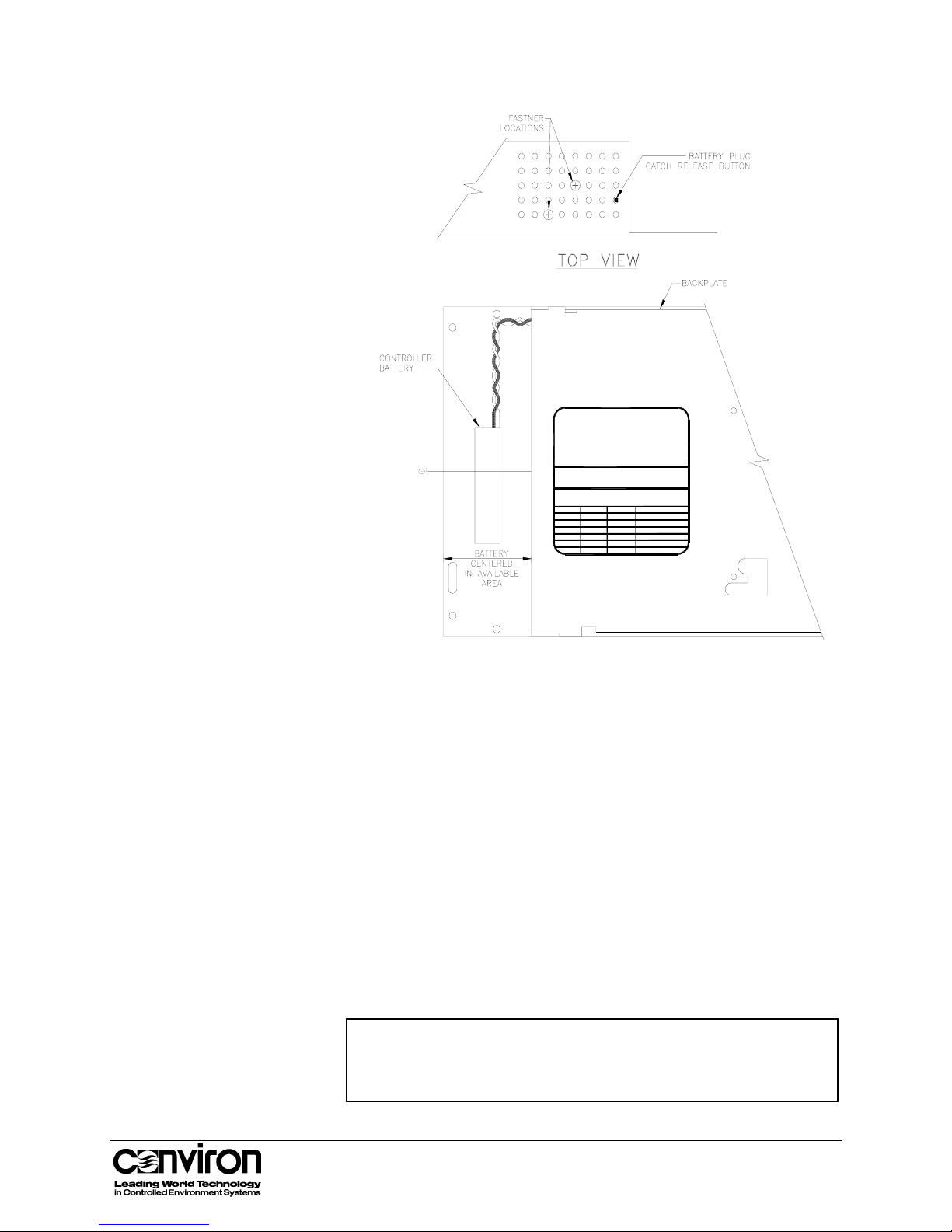
Controller Software Updates
70456
WARNING
HIS
EMOVE NLY
ATTERY
ONTROLLER
T
BW
OWER
P
battery
the Controller
Department and read
Service
only with
normal
maintenance
URNED
S
IT
when
and it will cease
to replace
to be
replaced every
Year
Controller
a Conviron
of the
the last dateshown below:beforeon or
HEN
C
N
O
power is turned off
to function.
the service manual
the battery.
approved
5 years
Controller and
Replaced by
part.
OR
Disconnecting
will damage
Conviron's
Contact
Replace
This
as part
must be
Month Day
this
before attempting
the battery
battery needs
of the
replaced
7. Remove the existing battery by separating the Velcro
fasteners.
8. To install the new battery, insert and lock its electrical
connector and join the Velcro fasteners.
9. Ensure the electrical connector and battery are secure.
10. Initial the current "replace by" date on the Warning Label.
Write a new “replace by” date that is 5 years in the future.
11. Test the new battery by turning the Controller Disconnect
switch to
OFF for 15 seconds and then ON again. If the
controller reboots completely and all functions operate
correctly, the replacement was successful. Specifically verify
the following functions:
• accept and run a program
• change time and date
• recognize the floppy disk drive, if so equipped
Note: When a battery is tested there is a risk of losing controller
memory. If the memory is lost, the controller must be replaced.
To avoid problems, perform the test when the chamber is not in
use.
7-7
Page 71

Chapter 7: Maintenance and Troubleshooting
Controller Software Updates
Conviron periodically releases new versions of controller
software.
Instructions for performing software updates are included in the
CMP4030 Service Manual. We recommend that service
personnel or users with advanced knowledge of the CMP4030
controller perform software updates.
Contact Conviron Customer Care for more information.
For more efficient service, please have the serial number of your
chamber available.
Conviron Customer Care
Toll free in North America
Local telephone
Fax
E-mail
Web address
1-800-363-6451
1-204-786-6451
1-204-783-7736
www.conviron.com
7-8 CMP4030 User Guide
November 2002
Page 72

Appendix A: Labels
This appendix lists and describes various labels displayed on the CMP4030
controller.
There are four label categories: Reference, Input, Output and Set Point. Each
label falls into one of the four categories.
Reference
• Reference labels describe useful information about the chamber, such as
the model type and/or serial number.
• The serial number is required for service.
Because the information is chamber specific, labels are not listed in the table
below.
Input
• Input labels describe parameters that are sensed by the input board or by
the TTL inputs.
• They can be monitored and logged.
Output
• Output labels describe parameters that are switched by the output boards.
• They can be monitored and logged.
Set Point
• Set Point labels describe parameters that are set in the Program screen.
• They are used to control the operation of the chamber.
• They can be monitored and logged.
App. A - 1
Page 73

Appendix A: Labels
Label Category Description
AUX1… output Auxiliary switch 1…
CFMTR output Circulating fan motor
CFMTR_SW input Circulating fan motor switch (for monitoring
fan status)
CO2 (CO2A) input Carbon dioxide sensor
COSVLV output CO2 solenoid valve
CSVLV output Cooling solenoid valve
CSW1… input Current switch 1… (for monitoring device
status)
DBDMTR output Dehumidification bypass damper motor
DDDMTR output Dehumidification drier damper motor
DECFMTR output Dehumidification evaporator circulating fan
motor
DECSVLV output Dehumidification evaporator cooling
solenoid valve
DEHMVLV output Dehumidification evaporator modulating
valve
DEHSVLV output Dehumidification evaporator heating
solenoid valve
DHTR output Defrost heater
DRIER output Dehumidification chemical (desiccant) drier
DRIER_OFF
set point Dehumidification drier off delay
(SP_DRIER_OFFDLY
)
DRIER_ON
set point Dehumidification drier on delay
(SP_DRIER_ONDLY)
DSVLV output Drain solenoid valve
EDMTR output Exhaust damper motor
FLUOR1… output Fluorescent lamp 1…
FLUORbnk output Fluorescent lamp bank
App. A - 2 CSMP4030 User Guide
November 2002
Page 74

Label Category Description
FLUOR_VOLTS input Fluorescent volts (for controlling dimming
ballasts)
HCMTR output Centrifugal atomizing humidifier motor for
additive humidity
HCMVLV output Heat/cool modulating (proportional) valve
HPSOD1… output High pressure sodium lamp 1…
HSVLV output Heating solenoid valve
HTR1… output Electric heater 1…
HUM
input Humidity (%RH)
(HUM_100)
IMµMOL input Input module light meter micromole
INCANbnk output Incandescent lamp bank
LOFT_TEMP1 input Lamp loft temperature
MHAL1… output Metal halide lamp 1…
HPRSW (PR_HIGH) input Refrigeration pressure switch - high
HLPRSW (PR_HILO) input Refrigeration pressure switch - high/low
LPRSW (PR_LOW) input Refrigeration pressure switch - low
SNVLV output Spray nozzle solenoid valve for additive
humidity
SODIUMbnk output High pressure sodium lamp bank
SP_AUX1… set point Auxiliary 1…
SP_CO2 set point Carbon dioxide
SP_DRIER set point Chemical drier (dehumidifier)
SP_FLUOR set point Fluorescent lighting
SP_HPSOD set point High pressure sodium lighting
SP_HUM set point Humidity
SP_INCAN set point Incandescent lighting
SP_LIGHT set point Lighting (Combination of different types of
App.A - 3
Page 75
Appendix A: Labels
Label Category Description
lamps)
SP_MHAL set point Metal halide lighting
SUDLY output Start up delay (controls main contactor)
TEMP input
Temperature inside the plant growth area
Tip:
The TEMP label applies to both control and
alarm settings. Enter alarm limits that are
slightly beyond the experiment’s minimum
and maximum program conditions.
TIME-24HR_CLK set point Time
App. A - 4 CSMP4030 User Guide
November 2002
Page 76
Appendix B: Alarm Messages
This appendix describes standard alarm history messages, possible causes and
recommended solutions. For more information on these procedures, refer to
Chapter 7: Maintenance and Troubleshooting.
Additional information can be found in Conviron Service Bulletins.
Note: If the recommended solutions do not resolve the existing problem, contact
Conviron Customer Care.
Alarm code
Description A triac is "half waving"
Defaults
Cause Output board line voltage problem.
Solution 1. Ensure that the Start/Stop switch is set to ON.
Alarm code
Description An input reading is out of range.
Defaults
Cause Possible sensor or input board failure
Solution Ensure that the sensor is connected to input board properly.
Alarm code
Description An input reading has the wrong polarity
Defaults:
Cause Possible sensor failure
Solution Ensure that the sensor is connected to input board properly.
Alarm code
Description The actual value of an input is higher than its high limit level.
Defaults Defaults:
Cause 1. possible sensor location or aspiration problem
Solution Ensure that the limit settings in the Alarm screen are correct for the range of
1/2 wv; bd x ch y
• priority: 75
• User Interaction Level: not accessible
2. Check the line power to the board.
A-D ov rng; bd x ch y
• priority: 75
• User Interaction Level: not accessible
A-D pol; bd x ch y
• priority: 75
• User Interaction Level: not accessible
[input] inp ov lim: x y
• [input] is the input label that generated the alarm
• x is the value of the limit that was exceeded
• y is the actual input value at the time of the alarm
• priority: 75
• User Interaction Level: normal Alarm Screen
2. possible equipment failure
the program.
App. B-1
Page 77
Appendix B: Alarm Messages
Alarm code
Description The actual value of an input is lower than its low limit level.
Defaults
Cause 1. possible sensor location or aspiration problem
Solution Ensure that the limit settings in the Alarm screen are correct for the range of
Alarm code
Description An alarm event occurred for which the msgCode is undefined.
Solution Contact Conviron Customer Care
Alarm code
Description Reports an error writing an alarm record to the CCS (host).
Defaults
Cause Probable loss of connection to CCS.
Solution 1. Check thumbnail on host to ensure connection, if not:
Alarm code
Description Reports an error writing a alarm record to the floppy disk
Defaults
Cause Possible problem with the disk, drive or communication to it.
Solution
Alarm code
Description Power on boot up message
Defaults
Cause This message displays the length of time that the controller was off for and
Alarm code
Description Reports if the main contactor opens, causing the chamber to shut off while a
Defaults
Cause Possibly caused by a safety limit or the chamber on/off switch.
[input] inp und lim: x y
• [input] is the input label that generated the alarm
• x is the value of the limit that was exceeded
• y is the actual input value at the time of the alarm
• priority: 75
• User Interaction Level: normal Alarm Screen
2. possible equipment failure
the program.
Alm msgCode x y
alm to host
• priority: 75
• User Interaction Level: not accessible
2. Check Ethernet connections.
3. Check hub(s) are powered
alm to disk
• priority: 75
• User Interaction Level: not accessible
Check storage space on the floppy disk and the controller
BOOTUP/zero SRAM BOOTUP (off for x:xx)
This message cannot be disabled
• priority: 75
• User Interaction Level: not accessible
indicates whether the SRAM was zeroed.
This is a notification message only. No action is required.
Chamber Off
program is running
• priority: 20
• persistent
• delay: 60 seconds
• User Interaction Level: not accessible
.
App. B - 2 CMP4030 User Guide
November 2002
Page 78
Solution 1. Verify Start/Stop switch set to ON.
2. Check ITSO limits.
Will not appear if SUDLY is off
• Alarm limit shut down – alarm for limit raised.
• Program stopped – no alarm message
Alarm code
Description The chamber circulation fans have stopped unexpectedly.
Defaults
Cause Probable circulation fan problem
Solution Repair circulating fans as needed.
Alarm code
Description The controller could not open the next program in the chain. The current
Defaults
Cause Probable corrupt chain file.
Solution 1. Verify/correct the program to be chained to.
Alarm code
Description
Defaults
Cause
Solution
Alarm code
Description The next program in the chain is not compatible with the controller
Defaults
Cause Program is not compatible, usually because it was created in a previous
Solution Create a new program on the controller and chain the original program to it.
Alarm code
Description
Circulation fan failure (if equipped with monitoring)
• priority: 20
• delay: 30 seconds
• persistent
• User Interaction Level: not accessible
Could not follow chain: Error opening chain file
program will continue to run until the chain problem is corrected.
• priority: 40
• persistent
• User Interaction Level: not accessible
2. If the program is corrupt, it will need to be recreated.
Could not follow chain: Error opening program file
The controller could not open the current program to follow the chain. The
current program will continue to run until the chain problem is corrected.
• priority: 40
• persistent
• User Interaction Level: not accessible
Probable corrupt program file.
1. Verify/correct the program to be chained to.
2. If the program is corrupt, it will need to be recreated.
Could not follow chain: Program not compatible
configuration and cannot be run.
• priority: 40
• persistent
• User Interaction Level: not accessible
version of software or was copied from a chamber with a different
configuration
Data Logging reset & stopped x
1. The data log was reset on boot up and any data in it was lost.
x is the actual fault reason code
App. B-3
Page 79
Appendix B: Alarm Messages
Defaults
Cause
Solution
Alarm code
Description
Defaults
Cause
Solution
Alarm code
Description An error occurred writing logged data to the host
Defaults
Cause Probable lost connection to CCS
Solution 1. Check thumbnail on host.
Fault Code
1 the number of log items or the log cycle was out of range
2 the start time of one or more data blocks was 0 indicating a
memory failure.
3
4
• priority: 75
• User Interaction Level: not accessible
In most cases this message appears due to changes to controller
configuration. In this case the message is a notification only.
If the message persists, contact Conviron Customer Care.
an item in the log list no longer exists most likely because a
change was made to the chamber configuration without zeroing
the SRAM
an item index number was out of range indicating a memory
failure
log data crpt
The system is attempting to log data from a label that was not defined in the
configuration software
• priority: 75
• User Interaction Level: not accessible
May occur on boot up if the SRAM is corrupt.
Reboot the controller to clear SRAM.
log to host
• priority: 75
• User Interaction Level: not accessible
2. Check Ethernet connections
Alarm code
Description An error occurred writing logged data to the floppy disk.
Defaults
Cause Possible problem with the disk, drive or communication to it
Solution Check storage space on the floppy disk and the controller.
Alarm code
Description Logged data was lost due to an overflow of the data buffer.
Defaults
Cause Controller memory is full. Probable floppy disk or CCS connection problem.
Solution The LOOP/NO LOOP setting in the Options screen determines if this
log to disk
• priority: 75
• User Interaction Level: not accessible
log data lost: block x lost
• priority: 75
• User Interaction Level: not accessible
message displays. Four settings are possible.
NO LOOP, ALARM: (default) Stop logging to prevent overwriting of data. An
alarm is raised if the controller is unable to transmit data to the floppy disk or
CCS.
App. B - 4 CMP4030 User Guide
November 2002
Page 80
LOOP, ALARM: Logging is continuous by overwriting the oldest data. An
alarm is raised if the controller is unable to transmit data to the floppy disk or
CCS.
LOOP, NO ALARM: Overwrite the oldest data in internal memory. No alarm
is raised.
NO LOOP, NO ALARM: Stop logging when internal memory is full. No alarm
is raised.
Alarm code
Description An AC output board cannot detect power on any output.
Defaults 1. priority: 75
Cause No line power to output board. Possible main contactor or wiring problem.
Solution If the chamber has Chamber Off detection, this alarm will only be seen if:
Alarm code
lost power to OP x board y
2. User Interaction Level: not accessible
- a program is running
- the main contactor is closed
- there is no power to an output.
The alarm will not be raised if a fuse on the board blows.
If the chamber does not have Chamber Off detection, then:
1. If there is only one board, check it,
2. If all boards but SUDLY, check the SUDLY circuit between the line side of
the SUDLY output and the main contactor coil.
If all boards including SUDLY, check Start/Stop switch.
Alarm code: max ret exc get_bd_mem
Alarm code: max ret exc set_bd_mem
Description The controller failed to read or write a byte from an input board, 3 times.
Defaults
Cause These messages indicate a serious hardware problem.
Solution Contact Conviron Customer Care
Alarm code
Description The controller failed to read or write a byte from an input board, 3 times.
Defaults
Cause This message indicates a serious problem.
Solution Contact Conviron Customer Care.
Alarm code
Description
Defaults
Cause
Solution
• priority: 75
• User Interaction Level: not accessible
max ret exc; inp bd x
Maximum retries exceeded communicating with input board.
• priority: 75
• User Interaction Level: not accessible
max ret exc; out bd x
The controller failed to read or write a byte from an output board or the output
board reported a CRC error. Maximum retries exceeded communicating with
output board.
• priority: 75
• User Interaction Level: not accessible
This message indicates a serious problem.
Contact Conviron Customer Care
App. B-5
Page 81
Appendix B: Alarm Messages
Alarm code
Description The log handler could not read a buffer from SRAM.
Defaults
Cause Possible SRAM corruption.
Solution Reboot the controller and zero the SRAM.
Alarm code
Description The chamber humidity is outside of the tracking limits.
Defaults
Cause Possible incorrect settings or equipment problem.
Solution 1. Ensure that the limit settings in the Alarm screen are adequate. RH limits
Alarm code
Description Reports a failure to communicate on the local IO (RS485) bus.
Defaults
Cause Possible COMMS board failure
Solution 1. Clean and reseat the bus cables and sockets.
Alarm code
Description No response from the COMMS board to last sync command.
Defaults
Cause This message indicates a serious problem.
Solution Contact Conviron Customer Care.
Alarm code
Description The chamber has turned itself off because the temperature is outside of the
Defaults
r err; log hand fr sram
• priority: 75
• User Interaction Level: not accessible
RH TrcLim Warning x y
• x is the value of the limit that was exceeded (humidity set point +/- limit
value) at the time of the alarm
• y is the actual input value at the time of the alarm
• priority: 40
• delay: 10 minutes
• User Interaction Level: Alarm Screen
must allow a wide tolerance from set point.
2. If the settings are adequate, there is a possible equipment failure. Contact
Conviron Customer Care.
RS485 BUS
• priority: 75
• User Interaction Level: not accessible
2. Reboot the system.
3. If the error persists, replace the controller.
sync_timeout
• priority: 75
• User Interaction Level: not accessible
Temperature Limit Shutdown x y
deviation limits.
• x is the value of the limit that was exceeded
• y is the actual input value at the time of the alarm
• priority: 20
• persistent
• delay: 15 seconds
• User Interaction Level: normal Alarm Screen
App. B - 6 CMP4030 User Guide
November 2002
Page 82
Cause Possible incorrect settings or equipment failure
Solution 1. Ensure that the limit settings in the Alarm screen are sufficient for the
range of the program.
2. If they are sufficient, there is a possible equipment failure. Contact
Conviron Customer Care.
Alarm code
Description This is a warning that the chamber temperature is outside of the tracking
Defaults
Cause Possible incorrect settings or equipment failure
Solution 1. Ensure that the limit settings are sufficient.
Alarm code
Description Reports a condition where the chamber has turned itself off because the
Defaults
Cause Possible incorrect settings or equipment failure
Solution 1. Check the limit settings to make sure they are sufficient.
Temperature TrcLim x y
limits.
• x is the value of the limit that was exceeded (temperature set point +/- limit
value) at the time of the alarm
• y is the actual input value at the time of the alarm
• priority: 40
• delay: 5 minutes
• User Interaction Level: normal Alarm Screen
2. If they are sufficient, there is a possible equipment failure. Contact
Conviron Customer Care.
Temperature TrcLim Shutdown x y
temperature is outside of the user tracking limits.
• x is the value of the limit that was exceeded (temperature set point +/- limit
value) at the time of the alarm
• y is the actual input value at the time of the alarm
• priority: 20
• persistent
• delay 5 minutes
• User Interaction Level: normal Alarm Screen
After shut down on the tracking alarm, the controller will monitor the
temperature and will restart the chamber if the temperature is moving towards
the set limit. If the temperature is not moving towards the set limit, use one of
the following procedures.
Procedure A: If the temperature exceeded the limit by a small margin, widen
the setting so the chamber restarts.
If the temperature stabilizes let the chamber run and monitor for problems.
If the temperature continues to move away from the set limit, contact
Conviron Customer Care.
Procedure B: If the temperature has significantly exceeded the limit, turn the
chamber off and open the doors to let the temperature stabilize to ambient.
At ambient temperature, restart the chamber and monitor. (To restart, it will be
necessary to either stop and restart the program or cycle the power to the
chamber).
If the temperature continues to move away from the set limit for more than a
minute, contract Conviron Customer Care.
App. B-7
Page 83
Appendix B: Alarm Messages
Alarm code
Description The tracking alarm disabled via the manual over-ride switch.
Defaults
Cause Disable switch in ON position. This is a notification message only. No action is
Alarm code
Description A triac that should be powered off is on.
Defaults
Cause Possible defective triac or driver
Solution Contact Conviron Customer Care
Alarm code
Description The log handler could not write a buffer from SRAM.
Defaults
Cause Probable SRAM corruption.
Solution Reboot the controller and zero the SRAM.
Alarm code
Description The wet bulb temperature of a humidity input is higher than the dry bulb
Defaults
Cause Probable wet bulb maintenance or possible sensor failure.
Solution 1. Ensure correct water level in reservoir.
Tracking Alarm Feature Disabled
• priority: 60
• User Interaction Level: not accessible
required
triac on; bd x ch y
• priority: 75
• User Interaction Level: not accessible
w err; log hand to sram
• priority: 75
• User Interaction Level: not accessible
wb > db
temperature.
• priority: 30
• User Interaction Level: not accessible
2. Clean or replace wet sock.
App. B - 8 CMP4030 User Guide
November 2002
Page 84
1620 Alarm Messages
The following alarm messages pertain to units equipped with the 1620 TEMP_LIMIT
sensor only. This unit was discontinued in 1998.
TEMP_LIMIT is the label used in the Alarm screen of the CMP4030 controller to set the
limits in the 1620 device.
All of the sensors are located in the aspirator. The 1620 TEMP_LIMIT sensor is
approximately 4” long.
Alarm code
Description Chamber temperature has exceeded the high setting for TEMP_LIMIT.
Defaults
Cause Possible incorrect settings or device failure.
Solution Ensure that the TEMP_LIMIT settings in Alarm screen are above and below
Alarm code
Description Chamber temperature has exceeded the low setting for TEMP_LIMIT.
Defaults
Cause Possible incorrect settings or device failure.
Solution See 1620 ov lim x y
Alarm code
Description Reports a condition where the system has shut down the chamber because it
Defaults
Cause Probable communication problem or failed sensor.
Solution 1. Reboot the controller to re-establish communications to the 1620
1620 ov lim x y
x is the value of the limit that was exceeded
y is the actual input valve at the time of the alarm
• priority: 20
• persistent
• User Interaction Level: Alarm Screen
the ranges of the program.
Check TEMP_LIMIT in Diagnostics screen to ensure that the reading is not
‘frozen’.
a) reboot the controller to re-establish communications to the 1620.
b) if rebooting is unsuccessful, replace the 1620.
If the reading is not frozen, there is a possible mechanical problem. Contact
Conviron Customer Care
1620 und lim x y
• x is the value of the limit that was exceeded
• y is the actual input value at the time of the alarm
• priority: 20
• persistent
• User Interaction Level: Alarm Screen
1620 r err A bd 999
has been unable to read the 1620 sensor temperature for a period of 30
minutes or more.
• priority: 20
• persistent
• User Interaction Level: not accessible
2. If rebooting is unsuccessful, replace the 1620.
App. B-9
Page 85
Appendix B: Alarm Messages
Alarm code
Description The 1620 config register could not be read.
Defaults
Cause Probable communication problem or failed sensor.
Solution 1. Reboot the controller to re-establish communications to the 1620.
Alarm code
Description TEMP_LIMIT settings in CMP4030 memory are not the same as in 1620
Defaults
Cause Probable communication problem or failed sensor.
Solution 1. Reboot the controller to re-establish communications to the 1620.
Alarm code
Description The limit values could not be corrected after they were found to be wrong.
Defaults
Cause Probable communication problem or failed sensor.
Solution 1. Reboot the controller to re-establish the communications to the 1620
Alarm code
Description The 1620 config register is not in the proper state and cannot be corrected.
Defaults
Cause Probable communication problem or failed sensor.
Solution 1. Reboot the controller to re-establish communications to the 1620.
Alarm code
Description The CMP4030 was unable to write new low or high limit values to the 1620.
Defaults
Cause Probable communication problem or failed sensor.
Solution 1. Reboot the controller to re-establish communications to the 1620.
1620 r err B bd x
• x is the number of the input board the 1620 is connected to
• priority: 75
• User Interaction Level: not accessible
2. If rebooting is unsuccessful, replace the 1620
1620 r err C bd x
memory.
• x is the number of the input board the 1620 is connected to
• priority: 75
• User Interaction Level: not accessible
2. If rebooting is unsuccessful, replace the 1620.
1620 r err D bd x
• x is the number of the input board the 1620 is connected to
• priority: 75
• User Interaction Level: not accessible
2. If rebooting is unsuccessful, replace the1620.
1620 r err F bd x
• x is the number of the input board the 1620 is connected to
• priority: 75
• User Interaction Level: not accessible
2. If rebooting is not successful, replace 1620.
1620 w err B bd x
• x is the number of the input board the 1620 is connected to
• priority: 75
• User Interaction Level: not accessible
2. If rebooting is not successful, replace the 1620.
App. B - 10 CMP4030 User Guide
November 2002
Page 86

Appendix C: Features of Version 6.0 Software
User Interface
Smart features
Improved look and feel to all user screens
• Faster, easier and more intuitive.
• Keypads replace arrows for faster value entry.
• Better reaction to user touches.
• User friendly on-screen information.
• Trendgraph screen plots in a few seconds.
• Option screen can be opened with a program running.
• Tracking alarm capability for both temperature and humidity.
Faster bootup sequence with better information
• Fewer on-screen messages.
• Screen calibration automatically re-starts if an error is made.
• Error codes are included to aid in diagnosing configuration
problems.
Improved CCS interaction
• Faster file transfer.
• Synchronize time from the CCS.
• Improved CCS Login/Logout operation.
User adjustable dehumidification and defrost parameters
• Turn off dehumidification when it is not needed.
• Adjust defrost threshold and cycle times.
• An RH set point of 0 disables all humidification and
dehumidification functions.
• Chamber restarts at the current temperature if the temperature
in the chamber is beyond the limits of the controller settings.
• Current program continues if it is unable to follow the chain.
• Controller checks that the program is complete before saving it.
• Controller checks that the program is compatible before using it.
• Alarm priorities are saved during the reboot procedure.
• Enhanced error detection and alarm reporting.
• Boot up message reports how long the chamber was down and
if the SRAM was zeroed on boot up.
• Main contactor state is monitored (Chamber Off alarm).
• The chamber qualifies alarm conditions to prevent nuisance
alarms that are a result of the main contactor state.
App. C -1
CMP4030 User Guide
November 2002
Page 87

Appendix D: The Psychrometric Chart
Psychrometrics defines the relationship between air temperature and moisture
content and their effect on relative humidity and dew point.
The psychrometric chart graphically represents the relationship of air
temperature and moisture content. Developing an understanding of
psychrometrics and how to read the psychrometric chart will help you,
• understand how to recognize and interpret the influence of ambient
conditions on chamber operation and achievable humidity range.
• be aware of the performance capabilities of your chamber.
The psychrometic chart identifies five values.
1. dry bulb temperature – the air temperature read by a shielded sensor
or simply, the air’s temperature.
2. wet bulb temperature – a reading based on evaporative cooling effect.
To read the wet bulb temperature, cover a sensor using a wick that has
been thoroughly wetted and placed in a moving air stream. The cooling
effect of the evaporating water causes a lower temperature compared to
the dry bulb air temperature.
3. dew point temperature – the temperature at which condensation first
begins, as a mixture of air and water vapor is cooled. Above this
temperature, the moisture stays in vapor form in the air.
4. moisture content – the amount of water vapour in the air by weight.
This is also referred to as the humidity ratio.
5. relative humidity (percent saturation) – the percentage saturation of
the air at a given dry bulb temperature. Relative humidity is a relative
measure, because the moisture-holding capacity of air increases as air
is warmed. In practice, relative humidity indicates the moisture level of
the air compared to the airs moisture-holding capacity at the same
temperature.
App. D - 1
Page 88

Appendix D: The Psychrometric Chart
Using the Psychrometric Chart
If you know the dry bulb temperature of the air and any one of the other values,
you can determine the rest of the values.
Refer to the attached psychrometric chart. Using the values that you know,
locate their intersection on the chart to determine the other values.
Example 1
Determine the relative humidity.
• the dry bulb temperature is 25°C
• the wet bulb temperature is 20°C
1. Locate the 25° point of the dry bulb temperature on the chart.
2. Locate the 20° point of the wet bulb temperature on the chart.
3. Follow the chart lines until they intersect.
From the intersection, follow the chart lines of the other variables to determine
their values. The chart indicates that the relative humidity is 63%, the moisture
content is 0.0128 kg/kg and the dew point is 16.5°C.
Example 2
Determine the moisture content.
• the dry bulb temperature is 5°C
• the relative humidity is 60%
1. Locate the 5°point of the dry bulb temperature on the chart.
2. Locate the 60% relative humidity point on the chart.
3. Follow the chart lines until they intersect.
From the intersection, follow the chart lines of the other variables to determine
their values. The chart indicates that the moisture content is 0.0032 kg/kg, the
wet bulb temperature is 3.5
°C and the dew point is 2°.
When defining experiment values in the chamber, ensure that the combination
of values entered is possible.
By referring to the Psychrometric chart, we can determine for example,
• that the condition of a dry bulb temperature of 30°C with relative humidity
of 90% is achievable only with the lights off.
• The combination of a dry bulb temperature of 40°C and 60% relative
humidity is not achievable at all.
App. D - 2 CSMP4030 User Guide
November 2002
Page 89

Error! No text of specified style in document.
Understanding your Chamber’s Performance Capabilities
A chamber’s relative humidity operating range is defined by:
• the chamber’s options
• its physical operation
Lower Limit of Operation
• The cooling coil temperature determines the lower limit of operation. The
cooling coil usually runs between 4 – 5 degrees colder than the set air
temperature.
• If the lights are on in the chamber, the cooling coil runs between
6 –10 degrees colder than the set air temperature.
• Because the temperature of the cooling coil is slightly lower than the
temperature of the chamber, the dew point is met and condensation
occurs. The result is a dehumidification effect.
Note: The coil temperature cannot run below freezing. The condensation will
freeze on the coil and result in mechanical failure.
Note: This information is accurate assuming that the chamber is equipped with
the additive humidification option and is well sealed.
Lower Limit with Dehumidification
If your chamber is equipped with a dehumidification option, the lower limit of
achievable RH is determined by:
1. The type of dehumidification
• A coil type dehumidifier is limited by the same factors that affect the
chamber cooling coil. The temperature of the cooling coil is slightly lower
than the temperature of the chamber. Most importantly, its temperature
cannot go below 0°C or it will freeze.
• A desiccant type or chemical dryer is not affected by temperature but is
limited by the amount of moisture that the desiccant can absorb. These
types of dryers come in a variety of sizes, so this limitation can be
accommodated.
2. Ambient conditions and the amount of ambient air infiltrating the chamber.
• In this case, assume the ambient conditions have a humidifying effect. It
is a matter of the dehumidifier’s ability to remove moisture versus the
amount of moisture introduced through fresh air.
App.D - 3
Page 90

Appendix D: The Psychrometric Chart
Upper Limit of Operation
The upper limit of operation is determined by the effectiveness of the additive
humidity devices (such as spray nozzles), and the cooling coil temperature.
• The warmer the air, the more moisture it can hold. However, there are
physical limitations to how much moisture can be injected and absorbed
into the air. The temperature of the cooling coil is slightly lower which
causes moisture to be condensed out of the air.
• If the fresh air and exhaust ports are open to allow air and CO
exchange
2
with ambient, the conditions of the ambient air will affect the operational
limits of the chamber.
• The RH% of the ambient air is not valid in determining the effect, unless
the ambient temperature is the same as the chamber temperature,
because this is percentage saturation at a given temperature.
Determining Moisture Content
Refer to the psychrometric chart to determine the moisture content of the
ambient air and of the air inside the chamber.
• If the ambient air has lower moisture content than the air inside the
chamber, it will create a dehumidifying effect.
• If the ambient air has higher moisture content than the air inside of the
chamber, it will create a humidifying effect.
• At normal operating and ambient temperatures, the humidifiers in the
chamber can compensate for most dehumidifying effects.
• If the chamber’s operating temperature is low, the additive humidity effect
of the ambient air at normal temperatures will create a very high resultant
RH inside the chamber.
• If the chamber’s operating temperature is high, the dehumidifying effect of
the ambient air at normal temperatures will limit the chamber’s ability to
achieve high RH values.
• If the chamber does not have any additive humidification or
dehumidification options, the RH % inside the chamber is entirely
dependent on the operating temperature of the cooling coil and more
importantly, the ambient condition, (as some air infiltration always occurs).
App. D - 4 CSMP4030 User Guide
November 2002
Page 91
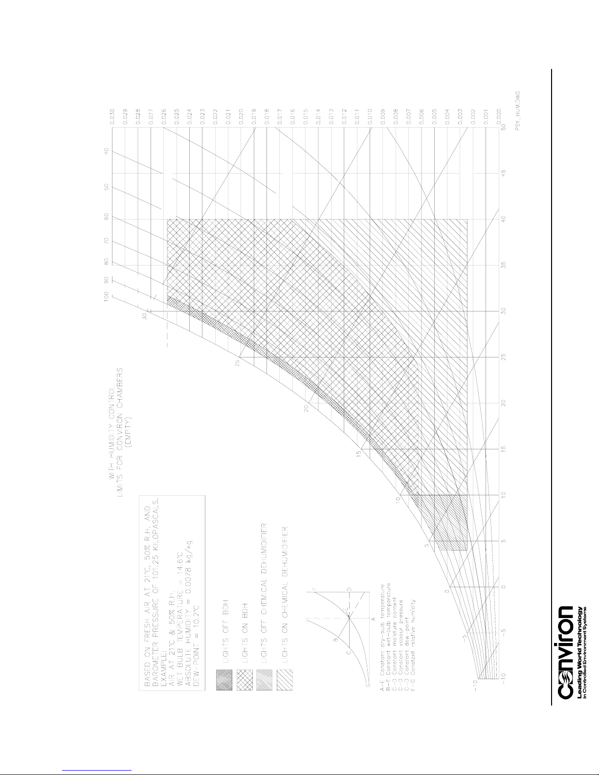
PERCENT SATURATION
MOISTURE CONTENT kg/kg ( DRY AIR )
LOW LIMIT FOR
BDH DEHUMIDIFICATION
IN TROPICS
MAXIMUM HUMIDITY
%
5
8
M
U
M
I
X
A
M
N
O
%
0
9
M
S
T
H
G
U
M
XI
A
I
M
L
F
F
O
S
T
H
G
I
L
LOW LIMIT FOR
CHEMICAL DEHUMIDIFIER
29°C DEWPOINT
CHART
PSYCHROMETRIC
C
°
E
R
U
T
A
R
E
P
M
E
T
B
L
U
B
T
E
W
DRY- BULB TEMPERATURE °C
App. D - 5
Page 92

Glossary
button
An active spot on the screen that performs an action when
touched.
Buttons on the CMP4030 screens contain text or icons.
CCS
cell
Acronym for Central Control System.
The individual entry points in the program table defined by the
intersection of any row (timeline) and any column (zone).
Central Control
System (CCS)
A remote control and monitoring system available for chambers
with CMP4030 controllers. Contact your Conviron sales
representative for more information.
chaining
The process of linking programs to run sequentially. If a
program is not chained to another program or to itself, it will stop
running at midnight.
Chaining a series of different programs together is referred to as
a multi-day program.
A program chained to itself will run continuously and repeat the
same program every 24 hours.
chamber
The entire unit is called the chamber. Parts of the chamber
include the control screen, the electrical panel, the refrigeration
system and the plant growth area.
controller
The device that sets and records the conditions in the plant
growth area according to a user created program. The
CMP4030 is the most recent controller model.
field
host
icon
Glossary-1
outputs
plant growth area
An area on the screen where data is displayed or is entered.
Another term for the Central Control System. It is more
commonly used in alarm messages and technical
documentation.
A graphical symbol.
Switches that control specific devices or conditions within the
chamber.
The environmentally controlled section of the chamber.
Page 93

Glossary
program
One or more timelines that create conditions in the growth area
during a 24-hour period. The timelines entered into the Program
Table indicate program conditions to the computer. A multi-day
program is a series of different programs, chained together.
An optional floppy disk drive or Host CCS may also be used to
store programs.
program table
The series of columns and rows used for entering program
timelines on the Program screen.
The intersection of a row and a column is a cell.
ramping
timeline
When conditions change gradually and steadily between
timelines. The CMP4030 works in ramping mode.
Any single row in the program table that contains a setting or
settings that define conditions in the plant growth area. For
example, temperature and relative humidity.
One or more timelines make up a program.
toolbar
A series of buttons that usually displays at the top of a screen.
The buttons provide shortcuts to specific functions such as
on-line help, security and exit.
zone
An area of the chamber that is independently controlled or
monitored.
Glossary-2 CMP4030 User Guide
November 2002
 Loading...