

Page 1
Page 2

CONVEX
Computer
Corporation
3000 Waterview
Parkway
P.O.
Box
833851
Richardson,
TX
75083-3851
United States
of
America
(214)497-4000
Page 3
CONVEX
Elite
3
Disc
Drive
Service Guide
Order
No. DHW-261
First Edition
April 1993
CONVEX Press
Richardson, Texas
United States of America
Page 4
CONVEX
Elite 3 Disc
Drive
Service
Guide
Order
No.
DHW-261
Copyright©
1993
CONVEX Computer Corporation
All rights reserved.
This document is copyrighted. This document
may
not,
in
whole
or
part, be copied, duplicated, reproduced, translated,
electronically stored,
or
reduced to machine readable form
without prior written consent from
CONVEX
Computer
Corporation.
Although the material contained herein has been carefully
reviewed, CONVEX Computer Corporation does
not
warrant
it to
be free of errors or omissions. CONVEX reserves the right to
make
corrections, updates, revisions
or
changes to the information
contained herein. CONVEX does
not
warrant the material
described herein to
be free of patent infringement.
UNLESS
PROVIDED
OTHERWISE
IN
WRITING
WITH
CONVEX
COMPUTER
CORPORATION
(CONVEX),
THE
PROGRAM
DESCRIBED
HEREIN
IS
PROVIDED
AS
IS
WITHOUT
WARRANTY
OF
ANY
KIND,
EITHER
EXPRESSED
OR
IMPLIED,
INCLUDING,
BUT
NOT
LIMITED
TO
THE
IMPLIED
WARRANTIES
OF
MERCHANTABILITY
AND
FITNESS
FOR A PARTICULAR
PURPOSE.
SOME
STATES
DO
NOT
ALLOW
THE
EXCLUSION
OF
IMPLIED
WARRANTIES.
THE
ABOVE
EXCLUSION
MAY
NOT
BE
APPLICABLE
TO
ALL
PURCHASERS
BECAUSE
WARRANTY
RIGHTS
CAN
VARY
FROM
STATE
TO
STATE.
IN
NO
EVENT
WILL
CONVEX
BE
LIABLE
TO
ANYONE
FOR
SPECIAL,
COLLATERAL,
INCIDENTAL
OR
CONSEQUENTIAL
DAMAGES,
INCLUDING
ANY
LOST
PROFl'IS
OR
LOST
SAVINGS,
ARISING
OUT
OF
THE
USE
OR
INABILITY
TO
USE
THIS
PROGRAM.
CONVEX
WILL
NOT
BE
LIABLE
EVEN
IF
IT
HAS
BEEN
NOTIFIED
OF
THE
POSSIBILITY
OF
SUCH
DAMAGE
BY
THE
PURCHASER
OR
ANY
THIRD
PARTY.
CONVEX and the CONVEX logo ("C") are registered trademarks of CONVEX
Computer
Corporation.
UNIX
is a registered trademark of UNIX System Laboratories, Inc.
Seagate, Seagate Technology,
and
the Seagate logo are registered trademarks
of
Seagate
Technology, Inc.
Computer Products/Power Conversion America
is a registered
trademark
of
Computer
Products, Inc.
()
This book is recyclable excluding cover
and
binding.
Printed in the United States of America
Page 5
Revision
information
for
CONVEX
Elite 3 Disc
Drive
Service
Guide
Edition Document No. Description
First
081-010230-000 Released April
1993.
Page 6
Contents
l'r4tfCIC:ft
••••••••••••••••••••••••••••••••••••••••••••••••••••••••
lci
Purpose and audience ................................................................ xi
Using this guide .......................................................................... xi
Notational conventions .............................................................. xi
Notes
and
cautions .................................................................... xii
Associated documents .............................................................. xii
Ordering documents ................................................................. xii
Technical assistance .................................................................. xiii
FCC notice .................................................................................. xiii
Electrostatic discharge protection .......................................... xiii
1
Description
and specifications ............... 1
Drive specifications ..................................................................... 1
de power requirements ......................................................... 3
Front panel indicators and switches ................................... 4
Control board jumpers .......................................................... 6
I/0
board jumpers ................................................................. 8
Power supply specifications ....................................................... 9
Elite 3 chassis ...............................................................................
11
2 Unpacking and
installation
...................
13
Unpacking and inspection ....................................................... 13
Inspection .............................................................................. 13
Unpacking .............................................................................
13
Damage claims .....................................................................
14
Preparations .......................................................................... 14
Installing power strip
and
disc tray ..................................
14
Installation ..................................................................................
14
Installing the Elite 3 chassis ................................................ 16
Connecting a single drive ................................................... 17
Connecting multiple disc drives ........................................
20
Physical configuration ......................................................... 22
3 Integration and
testing
..........................
27
Software integration .................................................................. 27
General integration procedure ........................................... 27
Contents v
Page 7
I ioconfig file ..........................................................................
28
I
etc/
disktab .......................................................................... 30
Testing the Elite 3 disc drive
with
idcfmt
............................
31
Verifying format ...................................................................
31
Formatting a drive ...............................................................
32
4 Maintenance
and
IPB
............................
33
Troubleshooting ..........................................................................
33
Elite 3 disc drive error codes ...............................................
33
Fault symptom code
(FSC)
..................................................
35
Sector errors ..........................................................................
44
FSC
codes reported
during
autoconf
............................. 45
WM
messages ..................................................................... 45
Determining disc usage ....................................................... 46
Removal
and
replacement procedures ................................... 48
Elite 3 chassis ........................................................................ 48
Disc drive ............................................................................... 48
Power supply ........................................................................ 49
Operator panel ...................................................................... 49
Fan assembly .........................................................................
50
Air filter .................................................................................
51
Illustrated parts breakdown
(IPB)
...........................................
52
A idcfmt ( 1
D)
man
page
..........................
55
vi
Elite 3 Disc
Drive
Service
Guide
Page 8
Figures
Figure 1
Figure2
Figure 3
Figure4
Figures
Figure6
Figure 7
Figures
Figure9
Figure 10
Figure
11
Figure
12
Figure
13
Figure
14
Figure
15
Figure 16
Figure 17
Figure
18
Figure
19
Figure20
Figure21
Figure22
Figure23
Figure24
Front panel ...................................................................... 4
Control board jumper location..................................... 6
J/O
board jumper locations .......................................... 8
Power
supply
component location ............................ 10
Elite 3 chassis ............. ...................................... .............
12
Additional power strip location.................................
15
Elite 3 disc tray.............................................................. 16
Connecting a single drive............................................ 17
JDC bulkhead
port
assignments for C3200/C3400.
18
JDC
bulkhead port assignments for C3800 ...............
19
Connecting multiple drives........................................
21
JDC
maximum drive configuration...........................
23
Expansion cabinet drive locations for 32 drives......
24
Expansion cabinet drive locations for 16 drives......
25
/ioconfig example 1 .....................................................
29
/ioconfig example 2 .....................................................
29
Example I
etc/
disktab ................................................. 30
WM
device failure message ...................................... 45
WM
completion message .......................................... 46
Determining disc usage
with
df
I
grep..................
46
Determining disc usage from
/etc/fstab
.................. 47
Elite 3 operator panel cable routing...........................
50
Air filter access..............................................................
51
Illustrated parts breakdown (IPB) .............................
52
Figures
vii
Page 9

Tables
Table 1
Table2
Table3
Table4
Tables
Table6
Table 7
Table8
Table9
Table
10
Table
11
Table
12
Table
13
Drive specifications ......... ........................ ........................ 1
Elite 3 disc drive de
power
requirements..................... 3
Elite 3 front panel indicators
and
switches .................. 5
Control board jumper block
J12
pin
assignments ....... 7
1/0
board jumper block
pin
assignments .................... 8
Power supply characteristics ...............
..
........................ 9
Power supply voltage specifications...........................
10
Power supply
pin
chart ..................................................
11
I
etc/
disktab description ............
..
................................
30
Elite 3 disc drive error codes........................................
34
FSC
field descriptions
..
....................................... ..........
35
FSC
descriptions ............................ ....... .................... .....
36
IPB
parts list ....................................................................
53
Tables
ix
Page 10

Preface
Purpose
and
audience
Notational
conventions
The CONVEX
Elite 3 Disc
Drive
Service
Guide
provides a general
overview of the Seagate Elite 3 disc drive and related equipment.
This guide describes how
to:
• Install the Elite 3 disc drive
and
related equipment
• Integrate the Elite 3 disc drive into the CONVEX operating
system
(ConvexOS)
This document is intended for:
• CONVEX customer support engineers
and
CONVEX
manufacturing personnel
• CONVEX customers who install
and
maintain their
own
Elite 3 disc drives and related equipment
This section discusses notational conventions used
in
this book.
Bold
mono
space
In command examples, text shown
in
bold
monospace
identifies user
input
that
must
be typed exactly as shown.
Mono
space
Italic
In paragraph text,
monospace
identifies:
• Command names
• System calls
• Data structures
and
types
In command examples,
monospace
identifies command output, including error
messages.
In command syntax diagrams, text
shown
in
monospace
must
be
typed exactly as
shown.
In paragraph text,
italic
identifies:
Preface
xi
Page 11
Notes
and
cautions
Note
Caution
Associated
documents
Ordering
documents
•
New
and
important terms
• Titles of documents
In command syntax diagrams,
italic
identifies variables
that
must
be
supplied
by
the user.
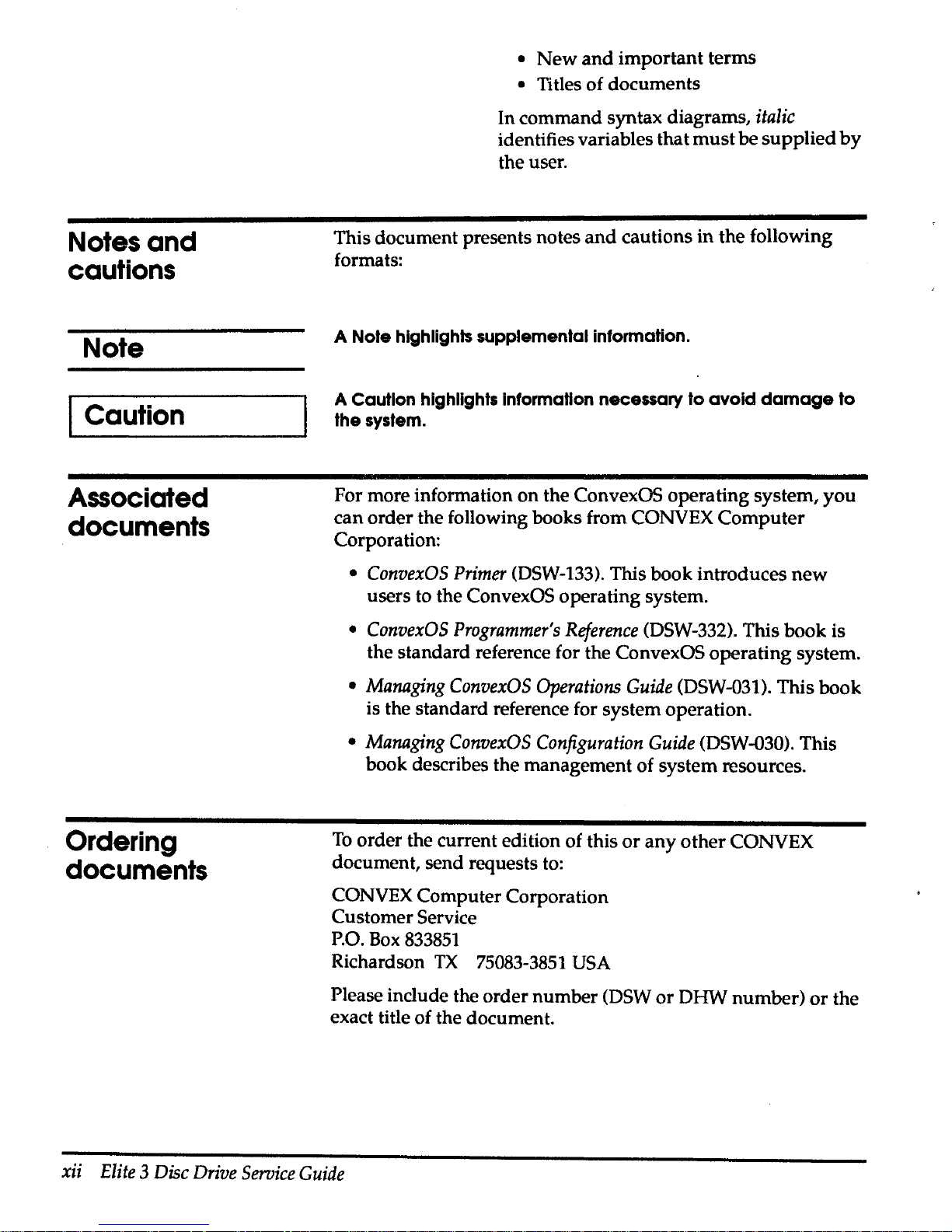
This document presents notes
and
cautions in the following
formats:
A Note highlights supplemental information.
A Caution
highlights Information necessary to
avoid
damage
to
the system.
For more information
on
the ConvexOS operating system,
you
can order the following books from CONVEX
Computer
Corporation:
•
ConvexOS
Primer
(DSW-133). This book introduces
new
users to the ConvexOS operating system.
•
ConvexOS
Programmer's
Reference
(DSW-332). This book is
the standard reference for the
ConvexOS operating system.
•
Managing
ConvexOS
Operations
Guide
(DSW-031). This book
is the standard reference for system operation.
•
Managing
ConvexOS
Configuration
Guide
(DSW-030). This
book describes the management of system resources.
To
order the current edition of this
or
any
other
CONVEX
document, send requests to:
CONVEX Computer Corporation
Customer Service
P.O.
Box
833851
Richardson
TX
75083-3851
USA
Please
include the order number (DSW
or
DHW number)
or
the
exact title of the document.
xii
Elite 3 Disc
Drive
Service
Guide
Page 12

Technical
assistance
FCC
notice
Electrostatic
discharge
protection
Caution
If
you
have questions that are
not
answered
in
this book, contact
the CONVEX Technical Assistance Center (TAC)
at
the
following locations:
• Within the continental U.S., call 1 (800) 952-0379.
•
From Canada, call 1(800)345-2384.
• From all other locations, contact the local CONVEX office.
You
may
also use the
contact
utility to report
any
problems
with
ConvexOS
or
its associated documentation. For more
information, refer to the contact(l)
man
page
in
ConvexOS
Man
Pages
for
Users,
or
the appendix ''Reporting problems"
in
the
ConvexOS
·Primer
or
Managing
ConvexOS:
Operations
Guide.
This equipment generates, uses
and
can
radiate radio frequency
energy.
If
the equipment is not installed
and
used
in
strict
accordance with the instruction manual,
it
may
cause
interference to radio communications.
This equipment has been tested
and
found to comply
with
limits
for a Class A digital device,
pursuant
to
Part
15
of
the
FCC Rules.
These limits are designed to provide reasonable protection
against harmful interference
when
equipment
is
operated
in
a
commercial environment.
When this equipment is operated in a residential area, it is likely
to cause interference. In this case, the interference
must
be
corrected at the operator's expense.
Do not connect external equipment to the utility outlets
in
CONVEX equipment cabinets. Unauthorized connection voids
all agencies' emissions certification.
The Elite 3
and
related assemblies are sensitive to static
electricity. Although some devices such as metal-oxide
semiconductors are extremely sensitive, all semiconductors, as
well as some resistors
and
capacitors,
may
be
damaged
or
degraded
by
exposure to static electricity.
Electrostatic damage to electronic devices
may
be caused
by
the
direct discharge of a charged conductor
or
by
exposure to the
static fields surrounding charged objects.
To
avoid
electrostaHc
damage,
service
personnel
must
observe
the
following
precautions
when
servicing
equipment:
Preface
xiii
Page 13

xiv
Elite 3 Disc
Drive
Service
Guide
• Ground yourself to the peripheral cabinet
or a grounded
service area whenever working
on
the Elite 3
or
related
assemblies, or whenever electronics will
be
exposed.
Connect yourself to ground with a wrist strap. Connection
may be made to any grounded metal assembly
in
the
peripheral cabinet. Remember that you
and
the electronic
devices must both be grounded to avoid potentially
damaging static discharges.
• Tum off power before removing
or
installing
power
cords.
• Shut down ConvexOS before cabling drives to the IDC
bulkhead.
•
Do
not remove any circuit boards from the drive.
• Never use an ohmmeter
on
any Elite 3 c.ircuit board.
Page 14

Description
and
specifications
1
Drive
specifications
Table 1 Drive specifications
Characteristics
Size
Interface
Capacity (bytes)
This chapter discusses the features, front panel functions,
and
electromechanical
and
physical specifications of
the
CONVEX
Elite 3 disc drive (CONVEX model DKD-505). The Elite 3 disc
drive
and
related hardware are designed to
be
used
with
the
CONVEX Integrated Disc Channel (IDC).
Table 1 contains the basic specifications for the Elite 3 disc drive.
Conditions
Specifications
Width
146
mm
(5.75
in.)
Height
83
mm
(3.25
in.)
Length
218
mm
(8.6
in.)
Weight
4.1
kg
(9.0
lb)
IPI-2E
(intelligent peripheral
interface)
Unformatted 3.1512019 Gbytes
Chapter 1 Description
and
specifications
1
Page 15
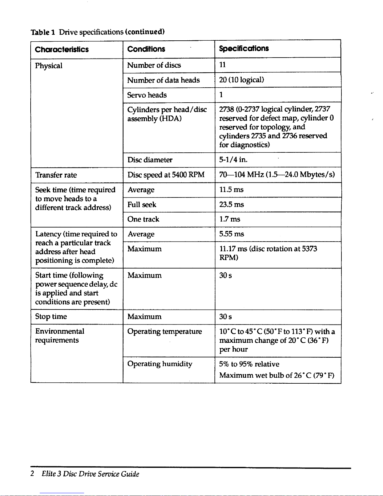
Table 1 Drive specifications (continued)
Characteristics
Conditions
Specifications
Physical
Number
of discs
11
Number
of data heads
20 (10 logical)
Servo heads
1
Cylinders
per
head/
disc
2738
(0-2737 logical cylinder, 2737
assembly (HOA)
reserved for defect map, cylinder
0
reserved for topology,
and
cylinders
2735
and
2736 reserved
for diagnostics)
Disc diameter
5-1/4
in.
Transfer rate Disc speed
at
5400 RPM
70---104
MHz
(1.5-24.0
Mbytes/s)
Seek time (time required Average
11.5ms
to move heads to a
different track address)
Full seek
23.5ms
One
track
1.7ms
Latency (time required to
Average
5.55ms
reach a particular track
Maximum
11.17
ms
(disc rotation
at
5373
address after head
positioning is complete)
RPM)
Start time (following
Maximum
30s
power
sequence delay,
de
is
applied
and
start
conditions are present)
Stop time Maximum
30s
Environmental
Operating temperature
10·c
to45°C
(50"Fto 113"F)
with
a
requirements
maximum change of
20"
C (36 • F)
per
hour
Operating humidity
5%
to
95%
relative
Maximum
wet
bulb
of
26 • C (79 •
F)
2
Elite
3
Disc
Drive
Service
Guide
Page 16
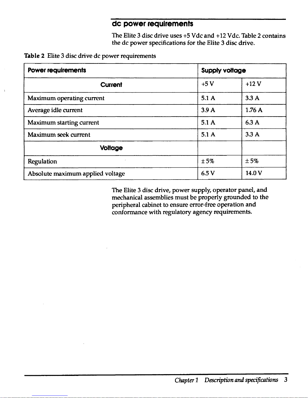
de
power
requirements
The Elite 3 disc drive uses
+5 V de
and + 12
V de. Table 2 contains
the
de
power specifications for the Elite 3 disc drive.
Table 2 Elite 3 disc drive de power requirements
Power
requirements
Supply
voltage
Current
+5V
+12V
Maximum
operating current
5.lA
3.3A
Average idle current
3.9A
1.76A
Maximum starting current
5.lA
6.3A
Maximum seek current
5.lA
3.3A
VoHage
Regulation
±5%
±5%
Absolute maximum applied voltage
6.5V
14.0V
The Elite 3 disc drive, power supply, operator panel,
and
mechanical assemblies
must
be
properly
grounded
to
the
peripheral cabinet to ensure error-free operation
and
conformance with regulatory agency requirements.
Chapter 1 Description
and
specifications
3
Page 17
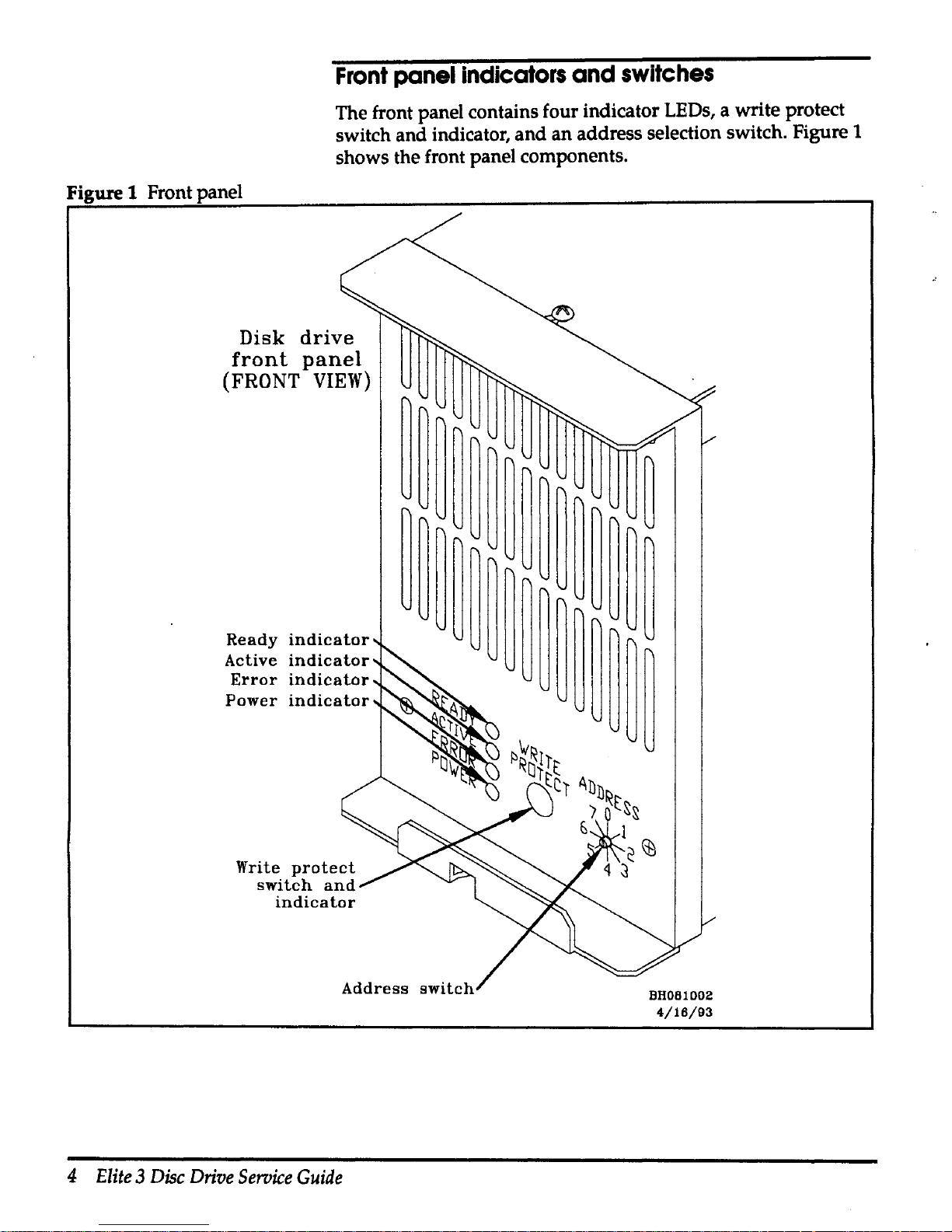
Front
panel
indicators
and
switches
The front panel contains four indicator LEDs, a write protect
switch and indicator,
and
an
address selection switch. Figure 1
shows the front panel components.
Figure
1 Front panel
Disk
drive
front
panel
(FRONT
VIEW}
Ready
indicator
Active
indicator
Error
indicator
Power
indicator
Address
switch
4
Elite 3 Disc
Drive
Service
Guide
BHOB1002
4/16/93
Page 18
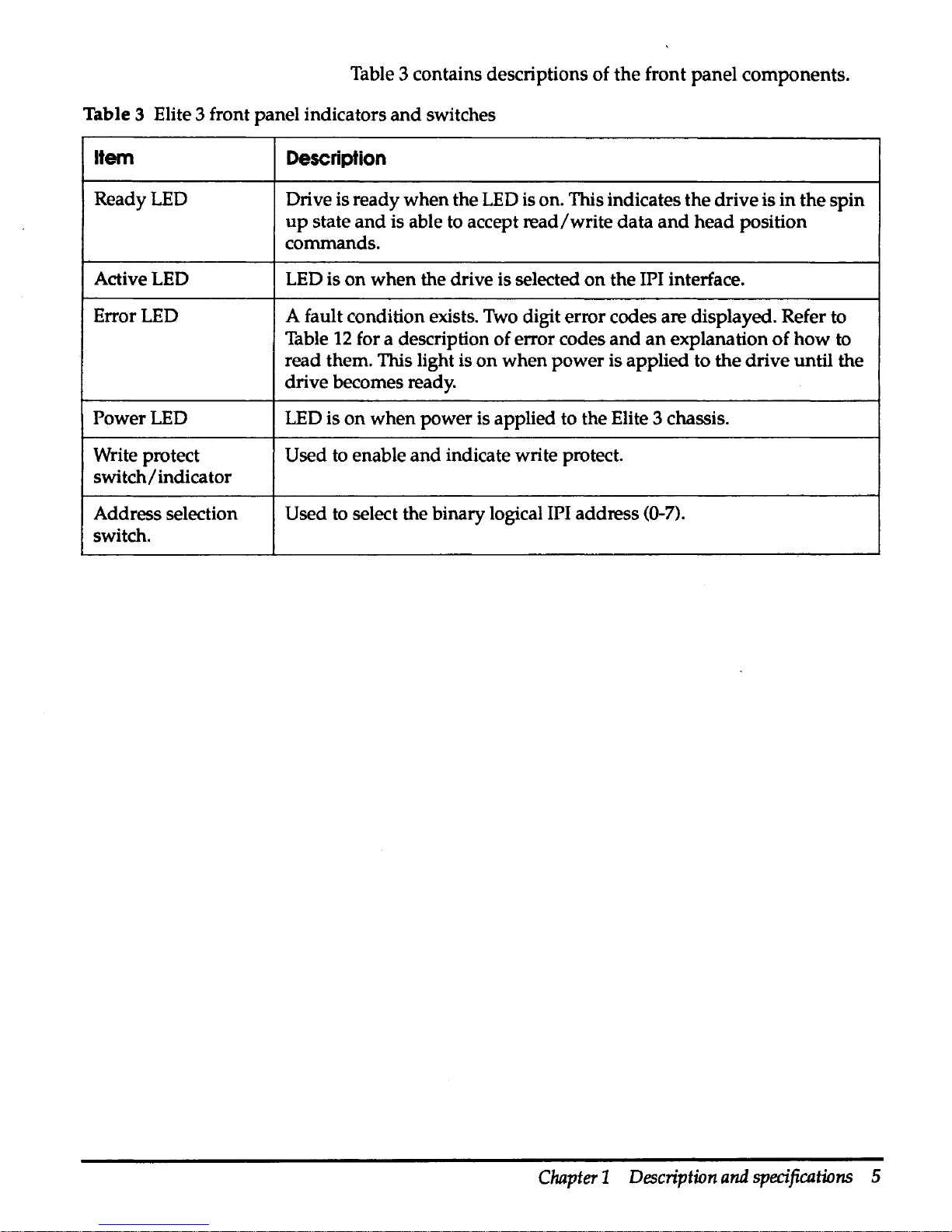
Table 3 contains descriptions of
the
front panel components.
Table 3 Elite 3 front panel indicators
and
switches
Item
Description
Ready LED
Drive is ready when the
LED
is on. This indicates the drive is
in
the spin
up
state
and
is able to accept
read/write
data
and
head
position
commands.
Active LED
LED
is
on
when the drive is selected
on
the IPI interface.
Error LED
A fault condition exists.
Two
digit error codes are displayed. Refer to
Table
12
for a description of error codes
and
an
explanation
of
how
to
read them. This light is
on
when
power
is applied to the drive until the
drive becomes ready.
Power LED LED is
on
when
power is applied to the Elite 3 chassis.
Write protect
Used to enable
and
indicate write protect.
switch/
indicator
Address selection
Used to select the binary logical IPI address (0-7).
switch.
Chapter 1 Description
and
specifications
5
Page 19

Control
board
jumpers
The disc control board is located
on
the
top
of the disc enclosure.
Jumpers
J9,
Jll,
J16-J19,
and
JSO
are reserved for manufacturing
use only.
J12
controls drive configuration. Figure 2
shows
the
location of the control board jumpers.
Figure 2 Control board jumper location
~JlO
J5
J20
J15
J12
J16
J17
~
rn
J50
c=::::J
J9
rn
J23~
J11A
~
rn
rn
1111111111
J48
JllB
J19
rn
J18
~
AH261011
4/22/93
Jumper block
J12
is a vertical header located
on
the control
board. Drive configuration is controlled
by
installing
configuration jumpers between adjacent pins.
6
Elite 3 Disc
Drive
Service
Guide
Page 20
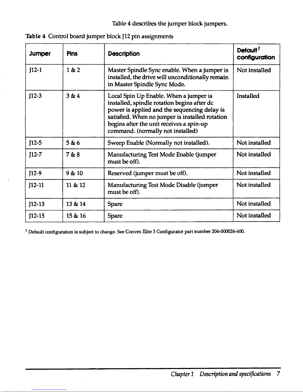
Table 4 describes the
jumper
block jumpers.
Table 4 Control board jumper block
J12
pin
assignments
Jumper
Pins
Description
Defautt
1
configuration
J12-1
1&2
Master Spindle Sync enable. When a
jumper
is
Not
installed
installed, the drive will unconditionally remain
in
Master Spindle Sync Mode.
J12-3
3&4
Local Spin
Up
Enable. When a jumper is Installed
installed, spindle rotation begins after
de
power
is applied
and
the sequencing delay is
satisfied. When no jumper is installed rotation
begins after the unit receives a spin-up
command. (normally not installed)
J12-5
5&6
Sweep Enable (Normally not installed).
Not
installed
J12-7
7&8
Manufacturing Test Mode Enable (jumper
Not
installed
must
be off).
J12-9
9&10
Reserved (jumper
must
be off).
Not
installed
J12-11
11 & 12
Manufacturing Test Mode Disable (jumper
Not
installed
must
be off).
J12-13
13&
14
Spare
Not
installed
J12-15
15&
16
Spare
Not
installed
1
Default configuration is subject
to
change. See Convex Elite 3 Configurator
part
number
204-000026-600.
Chapter 1 Description
and
specifications
7
Page 21

1/0 board
Jumpers
The
I/0
board has 4 jumper blocks (Wl,W2,W3
and
W4) for
configuring the drive.
Table 5
1/0
board jumper block
pin
assignments
Block Jumper
Pins
Description
Default'
configuration
Wl
Wl-1
1&3
Enable position calibrate
on
seek
Not
installed
Wl
Wl-2
2&4
Enable short
RPS
Not
installed
W2
W2-1
1&3
Disable
read/write
diagnostics
Installed
W2
W2-2
2&4
Reserved
Not
installed
W3
W3-1
1&3
Microcode configuration bit 2
Not
installed
W3
W3-2
2&4
Microcode configuration bit 3 Installed
W4
W4-1
1&3
Microcode configuration bit 0
Not
installed
W4
W4-2
2&4
Microcode configuration bit 1
Not
installed
1
Default configuration
is
subject
to
change. See Convex Elite 3 Configurator part number
204-000<Y26-600.
Figure 3 shows the relative location of the
I/0
board
jumpers.
Figure 3
I/
0 board jumper locations
J031
8
Elite 3 Disc
Drive
Seroice
Guide
J20
W2
W4
I I
DO
OJ
\
\,
Wl
J032
AH261012
4/5/93
Page 22

Power
supply
specifications
Computer Products Power Conversion America manufactures
the
NFS110-7602P power supply used
with
the Elite 3 disc drive.
Universal input voltage allows the
supply
to be powered
in
any
country without changing jumpers
or
switch settings.
Table 6 contains the power supply characteristics
and
Table 7
contains the power supply voltage specifications.
Table 6 Power supply characteristics
Parameter
Condition
Limits
Input voltage
85
Vac
to
264
Vac
Input frequency range
47
Hz
to 440
Hz
Input surge current Cold start
110
Vac
17 A maximum
Cold start
220
Vac
34Amaximum
Output voltage adjustability
+5.1
v
±3%
Over voltage protection threshold
+5.1
V output
6.25
v ±
0.75
v
Total output power@
50°
C ambient Convection cooled
0Wto80W
temperature
Peak
(60
s)
now
Operational environment
Operational altitude
10,000 feet
Nonoperational
40,000 feet
altitude
Operational
o·c
to
+5o·c
temperature
Nonoperational
-40°C to
+ss·c
temperature
Relative humidity
5%
to95%
Weight
1.55
lb
(0.70
kg)
Chapter 1 Description
and
specifications
9
Page 23

Table 7 Power supply voltage specifications
Output vottage
+5.1
v
+24V
+12V
-12V
Minimum current
OA
OA
OA
OA
Maximum current@
80
W
BA
3.5A
4.5 A
O.SA
Peak
current
20A
4.SA
9A
1.5A
Ripple p-p@ 50 MHz 50mV 240mV
120mV
120mV
Total regulation
±2%
+10/-5% ±3%
±3%
Figure 4 shows the component locations for the
power
supply.
Figure 4 Power supply component location
Pin
1
Jl
Pin
1
J2
5 A,
250
Vac
Fl
0
D
D
D
D
D
0
D
D
D
D
D
10
Elite 3 Disc
Drive
Seroice
Guide
11
Voltage
adjust
Tl
C6
0
0
AH261009
5/5/93
Page 24

Table 8 contains the
power
supply
connector pinout.
Table 8 Power supply pin chart
Connector
Location
Pin
number
Signal
Molex
099-50-3051
Jl
with second
and
fourth pins removed
Jl
Jl
Molex
09-50-3131
J2
J2
J2
J2
J2
J2
J2
J2
J2
J2
J2
J2
J2
Elite 3 chassis
Pin 1
acground
Pin2
ac neutral
Pin3
achot
Pin 1
+5.1
v
Pin2
+5.1
v
Pin3
+5.1
v
Pin4
Return
Pin5
Return
Pin6
Return
Pin 7 Return
Pin8
+12V
Pin 9 +12V
Pin 10
PFD
Pin
11
-12V
Pin
12
Removed for key
Pin
13
-24
v
The Elite 3 chassis, shown
in
Figure
5,
contains the Elite 3 disc
drive,
power
supply, fan assembly, operator panel, air filter,
interface cables,
and
power plug.
Chapter 1 Description
and
specifications
11
Page 25

Figure 5 Elite 3 chassis
12
Elite 3 Disc
Drive
Seroice
Guide
AH261013
4-/8/93
Page 26
Unpacking and
installation
2
Unpacking
and
inspection
Step 1
Step2
Step3
This chapter describes unpacking
and
inspection, identifies
major components of the Elite 3 disc drive
and
mechanical
package,
and
provides installation procedures.
This section gives general guidelines for unpacking
and
inspecting the Elite 3 disc drive
and
related assemblies.
Inspection
All shipping containers are designed to protect their
components
under
normal shipping conditions. Carefully
inspect each carton for signs of shipping damage as it is
unpacked.
If
damage is found after visual inspection, document
the damage with photographs
and
contact the transport carrier
immediately.
Unpacking
The customer's bill of materials lists all equipment shipped from
CONVEX.
It
should be used as a checklist to ensure that all
equipment has arrived.
Use the following procedure to unpack
the shipping container:
Remove each item from its shipping container.
Inspect each item for any signs of shipping
damage
as it is
unpacked.
If
equipment damage is found, document the damage,
and
proceed to the next section.
Save all packing material until after operational checkout of the
equipment. This enables equipment to
be returned safely to
CONVEX if required.
Chapter 2 Unpacking
and
installation
13
Page 27
Installation
Damage
claims
If the equipment is damaged, a damage claim form
must
be
completed. Damage claims should
be
completed
by
the
customer and given to the shipping representative. Claim forms
are normally obtained from the shipping representative.This
section describes the installation
of
the Elite 3 disc drive
in a high
performance peripheral cabinet (HPPC).
This section discusses the preparations for
and
installation of the
Elite 3 disc drive.
·
Preparations
Observe the electrostatic discharge procedures described
in
the
"Electrostatic discharge protection" section
on
page xiii, to
prevent damage
to
the drive
during
installation.
Installing
power
strip
and
disc
tray
An
additional power strip
must
be
added
to the
EXP-105
cabinet
to support the maximum number of Elite 3 disc drives. A
maximum of
24
drives may be installed.
The additional power strip is attached to the rear RETMA rail
centered between the existing power strips. Figure 6 shows the
location of the additional power strip.
14
Elite 3 Disc
Drive
Service
Guide
Page 28

Figure 6 Additional power strip location
Additional
power
strip
AH261004
4/16/93
Chapter 2 Unpacking
and
installation
15
Page 29
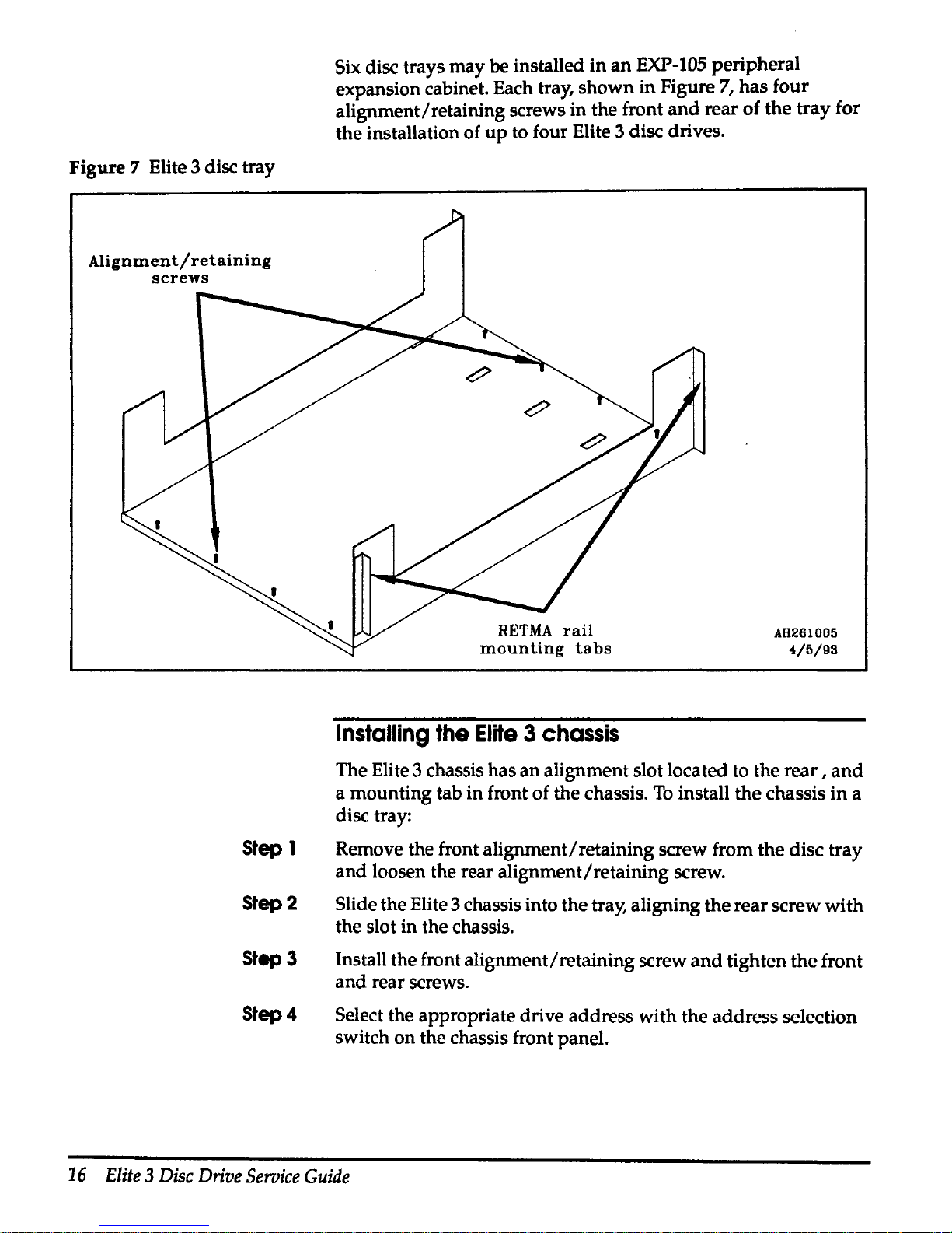
Figure 7 Elite 3 disc tray
Alignment/retaining
screws
Step 1
Step2
Step3
Step4
Six disc trays may be installed
in
an
EXP-105
peripheral
expansion cabinet. Each tray, shown in Figure
7,
has four
alignment/retaining screws in the front
and
rear of the tray for
the installation of
up
to four Elite 3 disc drives.
Installing
the
Elite 3 chassis
AH261005
4/5/93
The Elite 3 chassis has an alignment slot located to the
rear,
and
a mounting tab in front of the chassis.
To
install the chassis
in
a
disc tray:
Remove the front alignment/retaining screw from the disc tray
and
loosen the rear alignment/retaining screw.
Slide the Elite 3 chassis into the tray, aligning the rear screw with
the slot in the chassis.
Install the front alignment/retaining screw
and
tighten the front
and rear screws.
Select the appropriate drive address with the address selection
switch on the chassis front panel.
16
Elite
3
Disc
Drive
Seroice
Guide
Page 30

Caution
Step 1
Step 2
Step3
Connecting a single drive
Each Elite 3 disc chassis
has
3 connectors
at
the rear
of
the
assembly;
an
ac connector,
an
IPI
input
connector,
and
an
IPI
output
connector.
As root, use the
/etc/ebutdown
command
to
halt
ConvexOS
before connecHng a disc
to
the IDC. Failure
to
do
so
may
cause a
system crash
and
loss of data.
To
connect a single drive to
an
JDC:
Install the Elite 3 chassis
in
the peripheral cabinet.
Ensure the ac
power
switch
at
the
rear
of
the
Elite 3 chassis
is
in
the OFF position.
Attach the IPI cable to the
mate connector
on
the
rear
of
the
Elite
3 chassis.
Figure 8 Connecting a single drive
To
IDC
port
AH261008
4/5/93
Chapter 2 Unpacking
and
installation
17
Page 31
Step4
Attach the IPI cable to the appropriate JDC bulkhead connector.
It
is not necessary to remove power from the IDC
when
connecting disc drives to the IDC.
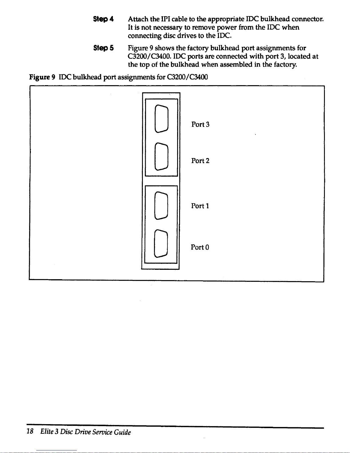
Step 5 Figure 9 shows the factory bulkhead
port
assignments for
C3200/C3400. IDC ports are connected with
port
3, located
at
the top of the bulkhead when assembled in the factory.
Figure 9 IDC bulkhead port assignments for C3200/C3400
0
Port3
0
Port2
0
Port 1
0
Porto
18
Elite 3 Disc
Drive
Seroice
Guide
Page 32
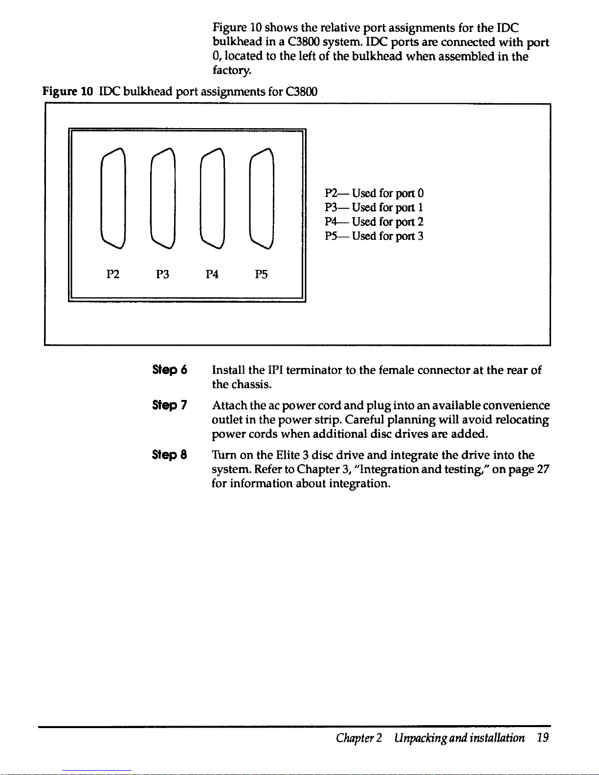
Figure 10
shows
the
relative
port
assignments
for
the
IDC
bulkhead
in
a C3800 system. IDC
ports
are
connected
with
port
0, located to the left
of
the
bulkhead
when
assembled
in
the
factory.
Figure 10 IDC
bulkhead
port
assignments for C3800
P2 P3
Step6
Step7
Step 8
P4
PS
P2-
Used
for port 0
P3-
Used
for port I
P4-
Used
for port 2
PS-
Used
for port 3
Install
the
IPI terminator to
the
female
connector
at
the
rear
of
the
chassis.
Attach
the
ac
power
cord
and
plug
into
an
available
convenience
outlet
in
the
power
strip. Careful
planning
will
avoid
relocating
power
cords
when
additional disc
drives
are
added.
Turn
on
the
Elite 3 disc
drive
and
integrate
the
drive
into
the
system. Refer to
Chapter
3, ''Integration
and
testing,"
on
page 27
for information
about
integration.
Chapter 2 Unpacking
and
installation
19
Page 33

Caution
Step 1
Step2
Step3
Step4
Step5
Step6
Connecting multiple disc drives
Each port
on
an
IDC can
support
up
to eight disc drives. These
may
be
any combination of DKD-501, DKD-502, DKD-503,
DKD-504, or DKD-505 disc drives.
As root, use the
/ate/shutdown
command
to
halt ConvexOS
before connecting a disc to the
IDC.
Failure
to
do
so
may
cause
a system crash and
loss
of data.
To
install multiple disc drives
on
an
IDC:
Install the Elite 3 chassis in the peripheral cabinet.
Ensure the ac power switches
at
the rear of the chassis are
in
the
off position.
Repeat Step 3 through Step 6 for each IDC
port
containing disc
drives. Refer to Figure
11
on
the following page.
Attach the
IPI cable to the IDC bulkhead port.
Attach the
IPI cable to the male connector
at
the rear of
the
first
Elite 3 disc drive in the daisy chain.
Install IPI daisy chain cables between additional drives
in
the
daisy chain.
Install the terminator
plug
on
the last drive in
the
daisy chain.
20
Elite 3 Disc
Drive
Service
Guide
Page 34
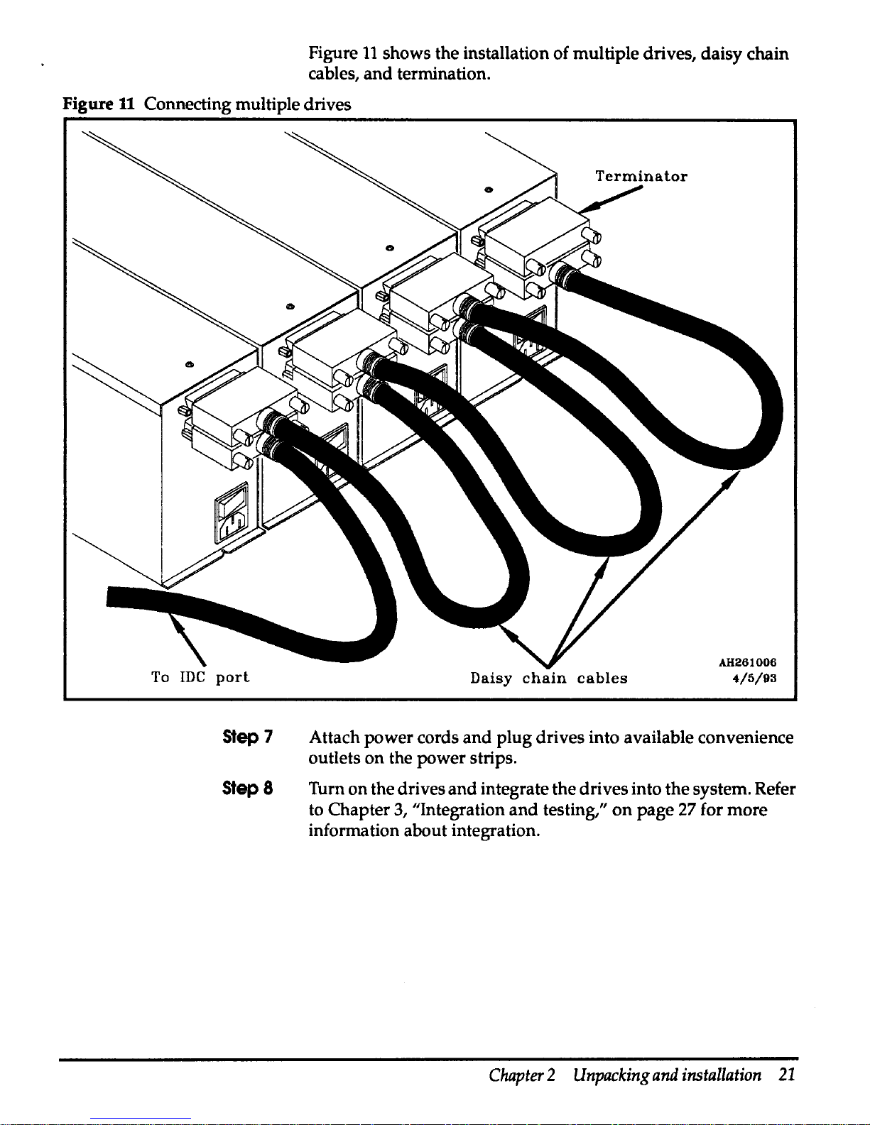
Figure
11
shows the installation of multiple drives, daisy chain
cables, and termination.
Figure
11
Connecting multiple drives
To
JDC
port
Step
7
Step8
Daisy
chain
cables
AH261006
4/5/93
Attach power cords
and
plug drives into available convenience
outlets on the power strips.
Turn on the drives
and
integrate the drives into the system. Refer
to Chapter
3,
"Integration
and
testing,"
on
page 27 for more
information about integration.
Chapter 2 Unpacking
and
installation
21
Page 35
Physical
configuration
A wide variety of configurations are possible
when
connecting
DKD-501, DKD-502, DKD-503,
DKD-504,
or
DKD-505
drives
to
an
IDC. The Elite 3 drives
may
be
added
to systems
that
currently contain Sabre 7
or
Sabre 5 disc drives. · ·
Each IDC can support
up
to
32
disc drives. The
maximum
cable
length
alln~edJ
between the IDC
and
the last disc
drive
is 100
'Ute.~
1.
~
'"2-S-
~
.
When planning your installation, consider the following
guidelines:
22
Elite 3 Disc
Drive
Service
Guide
• Group disc drives attached to a single IDC
port
together.
• Address drives in a consistent manner, starting
with
unit
0
in
the lower left-hand side
of
the cabinet,
and
incrementing
unit addresses horizontally.
• Allow for service access
when
placing the peripheral
cabinets.
• Generally, address switches determine drive numbers.
Page 36

Figure
12
shows the connection of
32
disc drives to
an
IDC.
Figure
U
IDC
maximum drive configuration
IPI
port
r::J. I I I
11
11
i 1
I
I I I
I
3
1~ve11m:ve11~vell
4
vel
drive
drive drive drive
4
5
6 7
IPI
port
T~
..
11~~11~~11~~11
~
..
11~~11~
..
11
~ve
I
2
IPI
port
r-1
I I I I I I I I I I I I I I
1
drive drive
drive drive drive
drive
drive drive
0
1 2
3
4
5
6 7
IPI
r-1
I
port
'TI'a
I I
1
0
drive
BJ
drive I drive I drive drive
drive
I
~
..
I
0
2 3 4 5
6
-
IDC
Chapter 2 Unpacking
and
installation
23
Page 37

A single peripheral expansion cabinet can contain a
maximum
of
24
Elite 3 disc drives. When connecting disc drives to
an
IDC,
disc drives attached to a single
port should
be
grouped
in
horizontal rows to allow the use of the single hot spare cable.
Figure
13
shows the relative locations of 32 Elite 3 disc drives
when
installed in 2 peripheral expansion cabinets.
Figure 13 Expansion cabinet drive locations for
32
drives
I
IPI
port2
drive4
IPI
port2
driveO
IPI
port 1
drive4
IPI
port 1
driveO
IPI-
portO
drive4
IPI
portO
driveO
I
First peripheral
expansion cabinet
Fan assembly
IPI IPI
port2
port2
drives
drive 6
IPI
IPI
port2
port2
drive 1 drive 2
IPI
IPI
portl
portl
drives
drive 6
IPI
IPI
portl
port 1
drive 1 drive2
IPI IPI
portO
portO
drive S drive6
IPI
IPI
portO portO
drive 1 drive 2
PDU
24
Elite 3 Disc
Drive
Service
Guide
11
IPI
port2
drive 7
IPI
port2
drive3
IPI
port 1
drive 7
IPI
port 1
drive 3
IPI
IPI
portO
port3
drive 7 drive4
IPI
IPI
portO
port3
drive 3
drive
0
I
I
Second peripheral
expansion cabinet
Fan assembly
IPI
IPI
port3 port3
drives
drive 6
IPI
IPI
port3 port3
drive 1 drive 2
PDU
I
IPI
port3
drive 7
IPI
port3
drive3
I
Page 38

Although it is possible for
an
IDC to
support
32
Elite 3 disc
drives, a typical configuration
may attach 16 Elite 3 disc drives
toanIDC.
Figure
14
shows
the
relative locations of 16 Elite 3 disc
drives
installed
in
a single peripheral expansion cabinet.
Figure 14 Expansion cabinet drive locations for 16 drives
Fan assembly
IPI
IPI
IPI IPI
port3
port3
port3 port3
driveO drive 1 drive2
drive3
IPI
IPI
IPI IPI
port2
port2
port2
port2
driveO
drive 1 drive2 drive3
IPI
IPI
IPI
IPI
portl
portl
port 1
portl
driveO drive 1 drive 2
drive3
IPI
IPI IPI
IPI
portO
portO portO
portO
driveO
drive 1 drive2
drive3
I
POU
I
Chapter 2 Unpacking
and
installation
25
Page 39
Integration
and
testing
3
Software
integration
Note
Step
1
Step2
Step3
Step4
Steps
Step6
Step
7
Step8
Step
9
Step
10
Step
11
This chapter contains guidelines for integrating Elite 3 disc
drives into
ConvexOS
and
information about the CONVEX
diagnostic tests.
Managing
ConvexOS
Configuration
Guide
(DSW-030) describes
device integration in detail. This section contains a summary of
the procedures used to
add
an Elite 3 disc drive
and
descriptions
of the system files that may require modification.
The
Elite 3 disc
drive
requires
ConvexOS
Vl
0.1
or
later.
Untll
ConvexOS
Vl
1.0
Is
released, a
sysgen
will
be
required
to
support
the
Ellte 3 disc
drive.
General
integration
procedure
The following steps are used to
add
a disc drive to the system:
Install the physical hardware.
Edit the /ioconfig
file.
Use
idcfmt
to verify operation
and
format.
Boot
ConvexOS to single-user mode.
Verify the entry in the
/etc/disktab
file.
Create block and character special device files using
MAKEDEV.
Create mount points.
Configure the partitions with
newfs
or
newst.
Edit /etc/fstab.
Use
preen
to check disc integrity.
Boot
ConvexOS to multiuser mode.
Chapter 3 Integration
and
testing
27
Page 40
/ioconfig
file
ConvexOS
uses
a configuration file
(/ioconfig)
located
on
the
service processor
unit
(SPU) disc to
identify
system
level
hardware.
The
/ioconfig
file describes
in
hierarchical
fashion
the
connections
between
the
integrated
disc
channels
(IDCs)
and
peripheral
devices. ConvexOS
uses
this
information
to
assign
a
logical
number
to a device
of a given
type.
Each
type
of
device is identified to ConvexOS
by
mnemonic
device
code. The device
and
marketing
code
for
the
Elite 3
disc
drive
is:
DKD-505-Elite
3 disc
drive
Elite 3 entries
in
the
/ioconfig
file
on
the
!:)PU
disc
contain:
• IDC
unit
number-Determined
by
physical
location
of
the
IOC
• IPI
port
number-Determined
by
connecting
to
the
JDC
•
Driver
number-Determined
by
device
driver
type
•
Unit
number-Determined
by
device
address
selection
•
Type-Device
code
for
the
device
• Logical
unit
number-Used
to create
the
desired
file
system
structure
(optional)
ConvexOS
uses
this information
during
autoconf
to
assign
a
logical device
number
of a given
type. This
determines
which
device files
found
in
the I dev
directory
will
be
used
for
each
disc
drive
identified
in
the
/ioconfig
file.
28
Elite 3 Disc
Drive
Seroice
Guide
Page 41
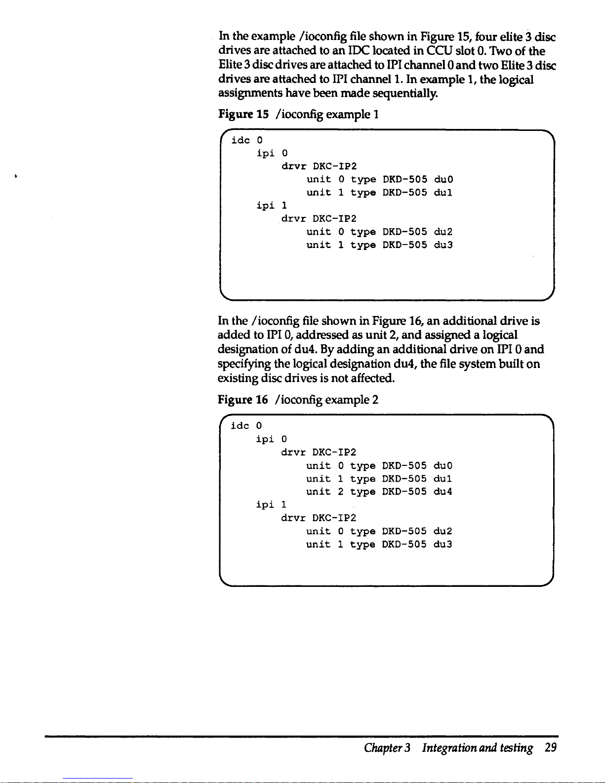
In
the example /ioconfig file
shown
in
Figure 15, four elite 3 disc
drives are attached to
an
JDC
located
in
CCU slot
0.
Two of the
Elite 3 disc drives are attached to
IPI channel 0
and
two Elite 3 disc
drives are attached to
IPI channel 1. In example 1, the logical
assignments have been
made
sequentially.
Figure
15 /ioconfig example 1
idc
0
ipi
0
drvr
DKC-IP2
ipi
1
unit
o
type
DKD-505
duO
unit
1
type
DKD-505
dul
drvr
DKC-IP2
unit
0
type
DKD-505
du2
unit
1
type
DKD-505
du3
In the /ioconfig file shown
in
Figure 16,
an
additional drive is
added
to IPI
0,
addressed as unit
2,
and
assigned a logical
designation of du4. By
adding
an
additional drive
on
IPI 0
and
specifying the logical designation du4, the file system built
on
existing disc drives is not affected.
Figure 16 /ioconfig example 2
idc
0
ipi
0
drvr
DKC-IP2
ipi
1
unit
0
type
DKD-505
duo
unit
1
type
DKD-505
dul
unit
2
type
DKD-505 du4
drvr
DKC-IP2
unit
O
type
DKD-505
du2
unit
1
type
DKD-505
du3
Chapter 3 Integration
and
testing
29
Page 42

/etc/disktab
The I
etc/
disktab file describes disc types, disc geometry, file
system partition sizes,and default block
and
fragment sizes. Do
not
change
/etc/disktab
if
an
entry for the Elite 3 disc
drive
exists.
Figure
17
contains the
/etc/disktab
entry for
an
Elite 3 disc
drive.
Figure
17
Example
/etc/disktab
rdkd-SOSIDKD-5051Elite3-2HPISeagate
ST43200K 3.0SGB
IPI-2
disk:\
:ty=winchester:spilS:set2048:nst53:nttlO:nct2734:rmt5400\
:pat70180:bat16384:fat2048:\
:pbt280555:bbl16384:fbi2048:\
:pct1402490:bct65536:fci8192:\
:pdf70540:bdt32768:fdt4096:\
:pei420320:bet16384:fet2048:\
:pfl140285:bfi16384iffi2048:\
:pgi631145:bgi16384:fgi2048:\
:phi420610:bhi16384:fht2048:
Table 9 shows
/etc/disktab
types
and
descriptions.
Table 9 /etc/disktabdescription
Name
Type/description
ty
Type of disc
se
Number of bytes
per
sector
sp
Number of spare sectors
per
cylinder
ns Number of sectors
per
track
nt
Number of tracks
per
cylinder
nc Number
of
cylinders
per
disc
rm
Disc speed (revolutions
per
minute)
p[a-h]
Partition sizes (sectors)
b[a-h]
Partition block sizes (bytes)
f[a-h]
Partition fragment sizes (bytes)
30
Elite 3 Disc
Drive
Service
Guide
Page 43
Testing
the
Elite 3
disc drive with
idcfmt
Caution
The Elite 3 disc drives are tested
by
the
idcfmt
diagnostic
program. There are two versions of
idcfmt.
The first version of
idcfmt
runs
on
the SPU
when
ConvexOS is not running. The
second version of
idcfmt
is
run
under
ConvexOS
as
root.
Appendix A contains the
idcfmt
man
page. The diagnostic
program:
• Formats disc drives
• Verifies previously formatted disc drives
• Performs disc maintenance
Some subtests
In
idcfmt
are
data
destructive. Refer to the
ldcfmt
(10) man
page
for a
detailed
description
of
idcfmt.
Verifying format
Elite 3 disc drives are formatted before shipping to the customer
site.
Use the
verify
option of
idcfmt
to ensure that the
drive
is correctly cabled to the system
and
has been formatted,
and
that each entry in the defect list points to a sector that has been
slipped.
idcfmt
is invoked by typing its name, a
-d,
followed
by
the
CCU slot number, IPI port number,
and
drive
unit
of the drive to
be used. A list of options may follow, then zero
or
more
commands.
If
no commands are given
on
the command line,
idcfmt
displays a prompt
and
expects commands to be entered
from standard input.
In the following example,
idcfmt
verifies the format
of
the
drive attached to the IDC in slot
0,
port
0,
unit
2.
idcfmt
-d
0 0 2
verify
Chapter 3 Integration
and
testing
31
Page 44

Caution
No
write operations occur
when
idcfmt
is
used
with
the
verify
option.
To
verify that the drive is formatted:
• Read one copy of all the data
on
the topology cylinder. Verify
that the checksums
and
magic numbers are correct.
• Read the remaining copies of the topology
data
and
verify
that they match the data from the first step.
• Read all logical blocks
on
the disc
and
verify that there
are
'
no header CRC
or
data ECC errors.
If
any
errors are found,
they are listed.
,
•
Read all the sector headers from the disc
and
verify that
there is a one to one correspondence of entries
in
the
defect
list with sectors that are slipped.
• Verify that each entry in the defect list points to a slipped
sector.
Formatting
a drive
The
format
command option is used
with
idcfmt
to format a
drive that has never been formatted.
If
a partial format is found,
the format resumes
at
the appropriate point,
with
the
manufacturers
and
grown defect lists that were
in
effect
when
the format was interrupted.
If
the drive has no valid format
on
it, then the program reads the manufacturers defect
data
from
the drive.
Under most circumstances a format is not required
in
the field.
Using
the
fo:mat
opHon
of
the
idcfmt
command
will destroy
any
existing flies on the disc drive.
In the following example,
idcfmt
formats
an
Elite 3 disc
drive
attached to the
JDC
in
slot
0,
port 0
and
addressed as
unit
2:
idcfmt
-d
0 0 2
fonnat
32
Elite 3 Disc
Drive
Service
Guide
Page 45

'
'
Maintenance and
IPB
4
Troubleshooting
This chapter contains maintenance precautions, removal
and
replacement procedures,
and
an
illustrated
parts
breakdown
(IPB).
This section contains information for interpreting
the
hardware
errors originating from the disc
drive
and
indicated
through
the
error light message codes. Information
about
the
fault
symptom
codes
(F'SC)
associated
with
the
disc
subsystem
is
also provided.
Elite 3 disc
drive
error
codes
The Elite 3 disc drive generates message codes for certain
circumstances
and
presents these codes to the JlO connector. This
connector is used to
drive
the error light
on
the
front panel.
Message codes consist
of
two digits
composed
of
the
numbers
1-9. The message code starts
with a long
pause
followed
by
short
pulses for the first digit, a short pause,
and
then
more
short
pulses for the second digit. The code
can
be
determined
by
counting the short pulses
that
represent the
two
digits.
In addition to being presented to
the
error
indicator on.the front
panel, FSCs associated with the
drive
messages
are
recorded
in
the
/mnt/errlog
file
on
the
SPU disc.
Chapter 4 Maintenance
and
IPB
33
Page 46

Table
10
contains descriptions of the error codes
generated
by
the Elite 3 disc drive.
Table
10
Elite 3 disc drive error codes
Error
Description
Corrective
action
code
11
Invalid micro code
ID-Switch
settings are
Check jumper installation
on
disc
incorrect
control board
21
Illegal
condition-Master
terminate
indicated,
but
the hardware did not indicate
the sending of
90
ending status
22
External RAM failure
23
Unexpected vectored
interrupt/trap
occurred
24
CSAW failure detect in power
up
Cycle power; if failure continues,
initialization
replace disc drive
25
Buffer memory failure detected in power
up
31
BIPIP IPC failure during power
up
32
BIPIP
SFC
failure
during
power
up
33
BIPIP
BUF
failure
during
power
up
34
BIPIP
VIB
failure
during
power
up
35
VIC failure
during
power
up
36
BIPIP
ECC
failure
during
power
up
34
Elite 3 Disc
Drive
Service
Guide
Page 47

Fault
symptom
code
CFSC)
Fault symptom code (FSC) is a standardized
method
for
reporting error conditions
on
the
CONVEX JDC
and
attached
JPJ
disc products.
The
FSC
is a hexadecimal code printed to the console
and
errlog
upon
detection of
an
error condition. The format
of
the
FSC is:
FSC
OxNNNN
idc
N
port
N
unit
N
cyl
OxNNN
trk
OxNNN
sec
OxNNN
p N
cnt
N
Table
11
contains a description of
the
FSC
fields.
Table
11
FSC
field descriptions
FSCfield
Description
FSCOxNNNN Hexadecimal representation of the fault symptom code.
idc
The
JDC
channel number that reported the error.
port The port
on
the
JDC
that reported the error.
unit The address of the drive that reported the error.
cylOxNNN
The hexadecimal cylinder number associated with the reported error.
This field is always reported even if the error
was
not a
data
or
seek
error.
trkOxNNN The hexadecimal track number associated
with
the reported error. This
field is always reported even
if
the error
was
not a
data
or
seek error.
secOxNNN
The hexadecimal sector number associated with the reported error. This
field is always reported even if the error
was
not a
data
or
seek error.
p
The partition number in which the error occurred. Partition 1 is a, 2 is b,
3 is c,
and
so on.
cnt
The number of times the operation was retried. Error threshold is
11.
If
the cnt field is less than
11
the retry succeeded.
Chapter 4 Maintenance
and
IPB
35
Page 48
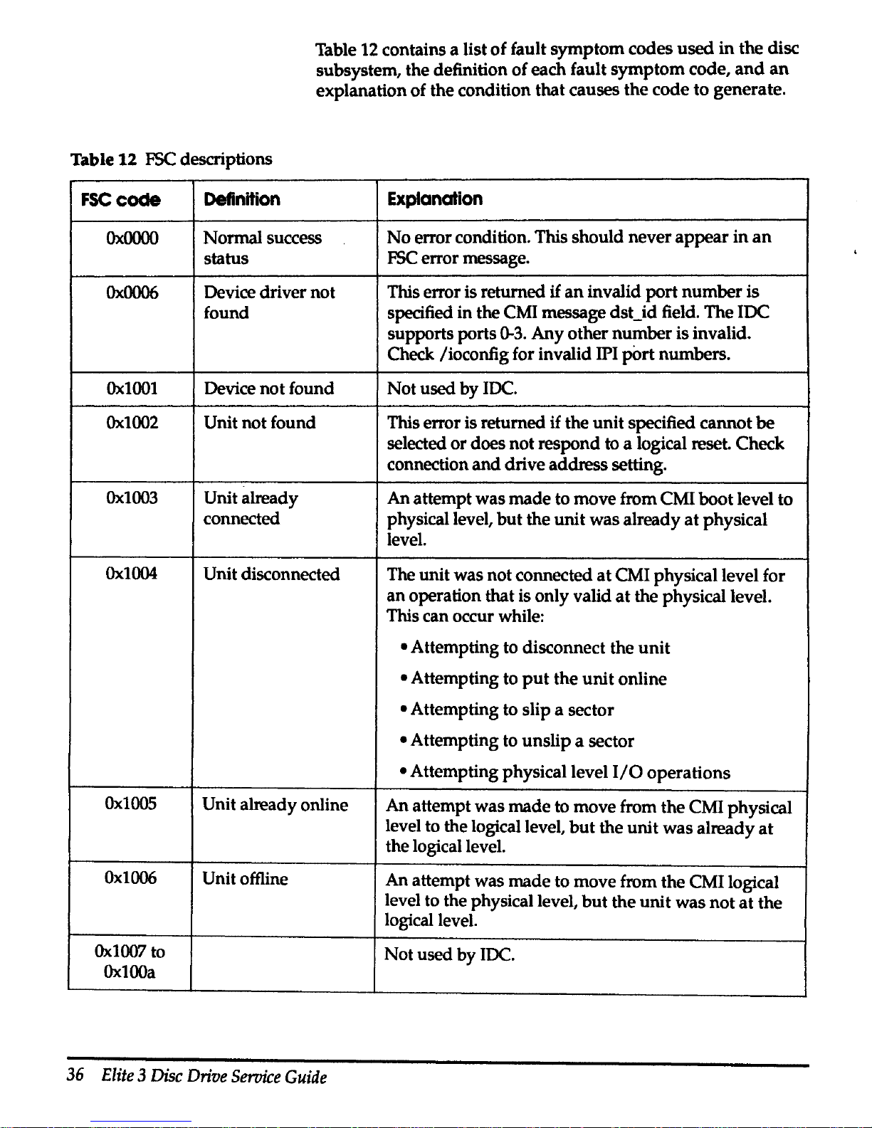
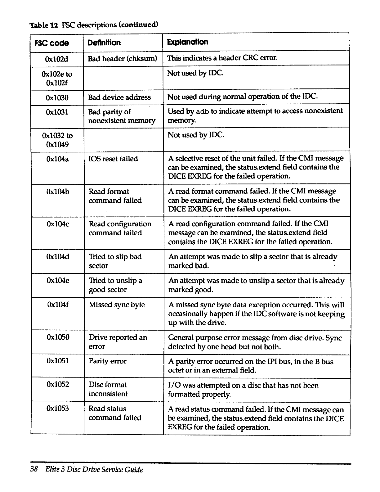
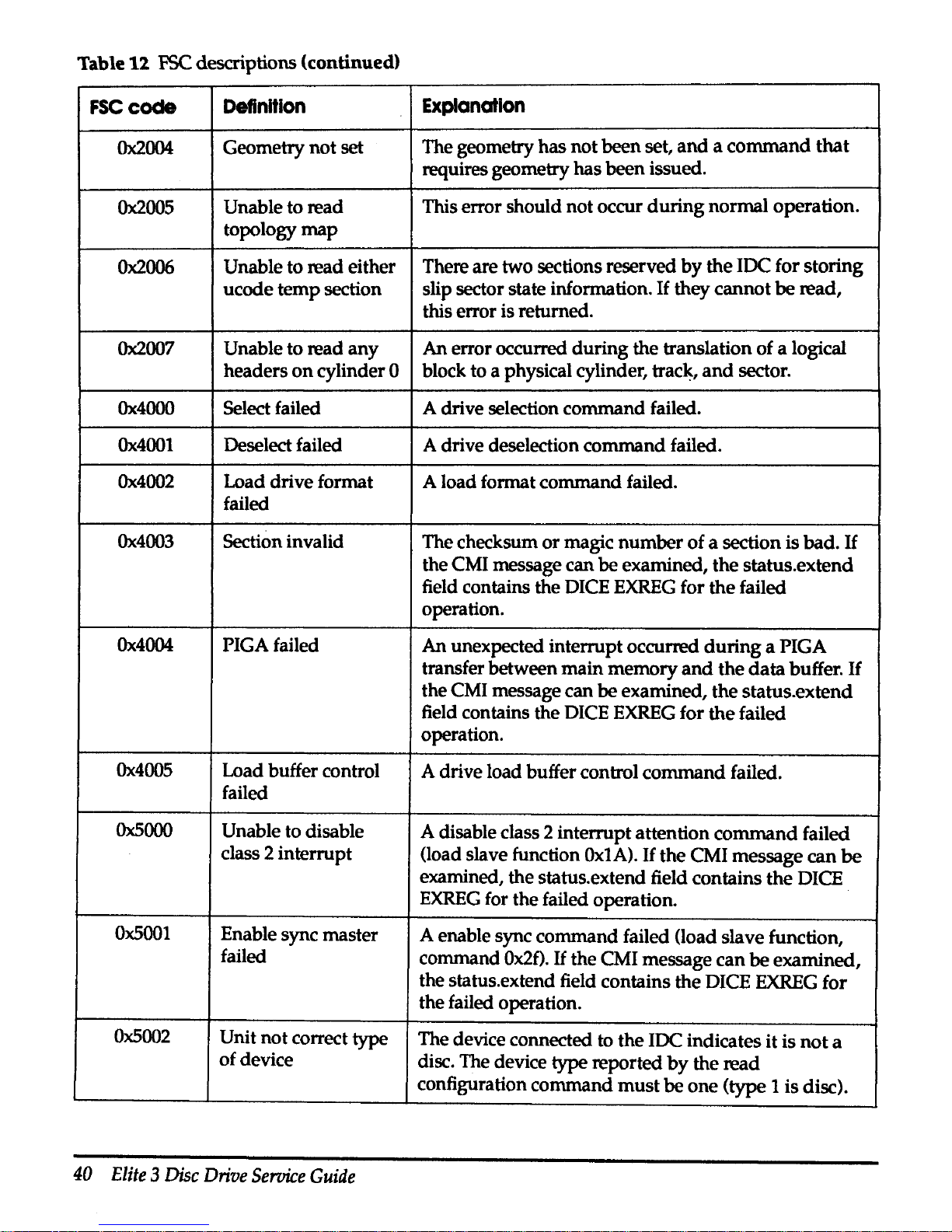
Table 12 contains a list
of
fault
symptom
codes
used
in
the disc
subsystem, the definition
of
each fault
symptom
code,
and
an
explanation of the condition
that
causes
the
code
to
generate.
Table
12
FSC descriptions
FSCcode
Definition
Explanation
Ox.0000
Normal success
No
error condition. This
should
never
appear
in
an
status
FSC
error message.
Ox0006
Device driver
not
This error is returned
if
an
invalid
port
number
is
found
specified in the CMI message dst_id field.
The
IDC
supports ports
0-3.
Any
other
number
is invalid.
Check /ioconfig for invalid IPI
p0rt
numbers.
Ox.1001
Device
not
found
Not
used
by
IDC.
Ox.1002
Unit
not
found This error is returned if the
unit
specified
cannot
be
selected
or
does
not
respond to a logical reset. Check
connection
and
drive
address
setting.
Ox.1003
Unit already
An
attempt
was
made
to move from CMI
boot
level
to
connected
physical level,
but
the
unit
was
already
at
physical
level.
Ox.1004
Unit disconnected
The
unit
was not connected
at
CMI physical level for
an
operation that is only valid
at
the physical level.
This can occur while:
•Attempting
to disconnect the
unit
• Attempting to
put
the
unit
online
• Attempting to slip a sector
•Attempting
to
unslip
a sector
•Attempting
physical level
I/0
operations
Ox.1005
Unit already online
An
attempt
was
made
to
move
from
the
CMI physical
level to the logical level,
but
the
unit
was
already
at
the logical level.
Ox1006
Unit offline
An
attempt was
made
to move from
the
CMI logical
level to the physical level,
but
the
unit
was
not
at
the
logical level.
Ox1007
to
Not
used
by
IDC.
OxlOOa
36
Elite 3 Disc
Drive
Service
Guide
Page 49

Table 12 FSC descriptions (continued)
FSCcode
Definition
Explanation
OxlOOb
Function time-out
The IDC timed
out
on
a read
or
write operation,
or
an
exceeded
expected attention from a
unit
did
not
arrive
prior
to
time-out.
OxlOOd
Function aborted
by
If
the IDC receives a DEBUG_FLIMBS message, all
CCU
pending operations
on
the specified device are
aborted
and
the error is posted.
OxlOOf
Invalid CMI function
An
invalid CMI function code
was
passed to the IDC.
code
Oxl012 to
Not
used
by
IDC.
Oxl015
Ox1016
CMI revision
An
invalid CMI revision level
was
passed
in
the CMI
unsupported
by
CCU device class field. For
the
IDC, the revision level
must
be
zero.
Ox1017
Defective CMI
The CMI message
was
defective.
message (badparms)
Oxl019 to
Not
used
by
IDC.
Ox
I Ole
OxlOlf Controller not The unit was not initialized
and
an
attempt
was
made
initialized
to connect, disconnect, set geometry, transition offline,
transition online, slip a sector,
unslip
a sector,
perform
physical
or
logical
1/0,
perform
long read
or
write,
or
read the configuration.
Ox1020to
Not
used
by
IDC.
Ox1027
Ox1028
Memory allocation This code is never printed
in
an
FSC error message.
It
(memalloc)
failed
is
used
with adb88 to indicate the breakpoint table is
full.
Ox1029
Not
used
by
IDC.
Ox102a
Unit not ready
The error is returned if the
drive
status cannot
be
read
or
if the device cannot
be
selected after reset.
Ox102b
Could
not seek to A seek error occurred.
required location
Ox102c
Recoverable IDC
An
ECC error occurred
and
the
data
was corrected.
ECCerror
Chapter 4 Maintenance
and
IPB
37
Page 50
Table
12
FSC descriptions (continued)
FSCcocle
Definition
Explanation
Ox102d
Bad header (chksum)
This indicates a header CRC error.
Ox102e
to
Not
used
by
IDC.
Ox102f
Ox1030
Bad device address
Not
used during normal operation
of
the
IDC.
Ox1031
Bad parity
of
Used
by
adb
to indicate attempt to access nonexistent
nonexistent memory
memory.
Ox1032
to
Not
used
by
IDC.
Ox1049
Ox104a
IOS reset failed
A selective reset of the
unit
failed.
If
the CMI message
can
be examined, the status.extend field contains
the
DICE
EXREG
for the failed operation.
Ox104b
Readformat
A read format command failed.
If
the CMI message
command failed
can
be examined, the status.extend field contains
the
DICE
EXREG
for the failed operation.
Ox104c
Read configuration
A read configuration command failed.
If
the
CMI
command failed
message can
be
examined, the status.extend field
contains the DICE
EXREG
for the failed operation.
Ox104d
Tried to slip
bad
An attempt was
made
to slip a sector
that
is already
sector marked bad.
Ox104e
Tried to unslip a An attempt was
made
to unslip a sector
that
is
already
good sector marked good.
Ox104f
Missed sync byte A missed sync byte
data
exception occurred. This will
occasionally
happen
if
the IDC software is
not
keeping
up
with the drive.
Ox1050
Drive reported
an
General purpose error message from disc drive. Sync
error
detected
by
one head
but
not
both.
Ox1051
Parity error
A parity error occurred
on
the IPI bus,
in
the B
bus
octet
or
in
an
external field.
Ox1052
Disc format
1/0
was attempted
on
a disc that has
not
been
inconsistent
formatted properly.
Ox1053
Read status
A read status command failed.
If
the CMI message can
command failed
be examined, the status.extend field contains
the
DICE
EXREG
for the failed operation.
38
Elite 3 Disc
Drive
Seroice
Guide
Page 51

Table
12
FSC
descriptions (continued)
FSCcode
Definition
Explanation
Ox1054
Recalibrate command
A drive recalibration command failed (load slave
failed
function, command
Ox28).
Ox1055to
Not
used
by
IOC.
Ox1057
Ox1058
Header
parity error
A parity error occurred
in
the header field.
Ox1059
Header
miscompare
The header
on
the disc
did
not match the
header
error
expected
by
the software. This will occasionally
happen if the
IOC software is
not
keeping
up
with
the
disc.
If
this error code is reported frequently, there
may be a disc hardware problem.
Ox1060
Drive verify header
This can be a data error
or
a true miscompare.
miscompare
Ox1061
Busy doing
General purpose error message from disc drive.
something else
Ox1062
Out
of spare General purpose error message from disc drive.
cylinders
Ox1063
Usually a warning, General purpose error message from disc drive.
not fatal
Ox1066
Read specification A drive read disc specification values
command
command failed.
Ox1067
Read buffer control A read buffer control command failed.
command failed
Ox1068
Read formatter A read slave formatter parameters command failed.
parameters failed
Ox1069
Recoverable drive The drive reported
it
detected
and
corrected a
data
ECC error error
on
the given sector.
Ox106a
Drive sent wrong
The drive sent a different sector
than
the
one
the IOC
sector
expected. The expected location of the missed sector is
printed
and
stored
in
the status.extend field of the
CMI message. This becomes a fatal error after
11
retries.
Ox106b
Drive buffer
The drive data buffer is temporarily unavailable. This
over
/underflow
becomes a fatal error after
11
retries.
Chapter 4 Maintenance
and
!PB
39
Page 52
Table
1l
FSC
descriptions (continued)
FSC
code
Definition
Explanation
Ox2004
Geometry not set
The geometry
has
not been set,
and a command
that
requires geometry
has
been issued.
Ox2005
Unable to read
This error should not occur
during
normal operation.
topology
map
Ox2006
Unable to read either
There are two sections reserved
by
the
IDC for storing
ucode
temp
section
slip sector state information.
If
they cannot
be
read,
this error is returned.
Ox2007
Unable to read
any
An
error occurred
during
the translation of a logical
headers
on
cylinder 0
block to a physical cylinder,
trac~,
and
sector.
Ox4000
Select failed A drive selection command failed.
Ox4001
Deselect failed A drive deselection command failed.
Ox4002
Load drive format
A load format command failed.
failed
Ox4003
Section invalid
The checksum
or
magic
number
of
a section is bad.
If
the CMI message can
be
examined,
the
status.extend
field contains the DICE
EXREG
for
the
failed
operation.
Ox4004
PIGAfailed
An
unexpected interrupt occurred
during
a PIGA
transfer between
main
memory
and
the
data
buffer.
If
the CMI message can
be
examined, the status.extend
field contains the DICE
EXREG
for
the
failed
operation.
Ox4005
Load buffer control
A drive load buffer control
command
failed.
failed
Ox5000
Unable to disable
A disable class 2 interrupt attention
command
failed
class 2 interrupt
(load slave function
OxtA).
If
the
CMI message can
be
examined, the status.extend field contains
the
DICE
EXREG
for the failed operation.
Ox5001
Enable sync master
A enable sync command failed (load slave function,
failed
command
Ox2f).
If
the CMI message can
be
examined,
the status.extend field contains the DICE
EXREG
for
the failed operation.
Ox5002
Unit not correct type
The device connected to
the
IDC indicates it is
not
a
of
device
disc. The device
type reported
by
the read
configuration command
must
be
one
(type 1 is disc).
40
Elite 3 Disc
Drive
Service
Guide
Page 53

Table 12
FSC
descriptions (continued)
FSCcode
Definition
Explanation
Ox5003
Uncorrectable IDC
An
uncorrectable ECC
error
occurred.
ECCerror
Ox5004
Load
head
command
The load head address
command
failed.
failed
Ox5005
Load target
The load
RPS
target sector
address
command
failed.
command
failed
Ox5006
Enable alternate sync
An
enable alternate sync byte
command
failed (load
byte failed slave function command
Ox35).
If
the CMI message
can be examined, the status.extend field contains
the
DICE
EXREG
for the failed operation.
Ox5007
Enable
primary
sync
An
enable primary sync byte
command
failed (load
byte failed
slave function command
Ox36).
If
the CMI message
can be examined, the status.extend field contains
the
DICE
EXREG
for the failed operation.
Ox5008
Uncorrectable drive The drive reported a
data
error
and
was
unable to
ECCerror
correct it with ECC.
Ox5009
Unable to enable
An
enable class 2 interrupt attention
command
failed
class 2 interrupt
(load slave function
command
OxlB).
If
the
CMI
message can be examined, the status.extend field
contains the DICE
EXREG
for
the
failed operation.
Ox500a
Unable to flush drive
A drive load
end
of write
command
failed.
If
the CMI
data
buffer
message can be examined, the status.extend field
contains the DICE
EXREG
for
the
failed operation.
OxSOOb
Unable to enable
An
enable slave ECC correction
command
failed (load
ECC correction
slave function command
Ox21).
If
the
CMI message
can be examined, the status.extend field contains
the
DICE
EXREG
for the failed
~peration.
OxSOOc
Unable to enable
An
enable slave ECC/CRC reporting
command
failed
ECC reporting
(load slave function
command
Ox2D).
If
the
CMI
message can be examined,
the
status.extend field
contains the DICE
EXREG
for the failed operation.
Ox500d
Unable to load buffer
A drive load buffer available
interrupt
delay
interrupt delay
command failed.
If
the CMI message can be examined,
the status.extend field contains the DICE
EXREG
for
the failed operation.
Chapter 4 Maintenance
and
IPB
41
Page 54

Table 12 FSC descriptions (continued)
FSCcode
Definition
Explanation
Ox500e
Unable to
tum
off
A disable slave ECC/CRC correction
and
reporting
driveECC
command failed (load slave function
Ox2C).
If
the CMI
message can
be examined, the status.extend field
contains the DICE
EXREG
for the failed operation.
0500£
Unable to enable
An
enable single
burst
ECC/CRC reporting
command
single burst report
failed (load slave function command
Ox8C).
If
the CMI
message can
be examined, the status.extend field
contains the
DICE
EXREG
for the failed operation.
Ox5010
Unable to disable
A disable single burst ECC/CRC reporting
command
single burst report
failed (load slave function command
Ox8D).
If
the
CMI
message can
be examined, the status.extend field
contains the DICE
EXREG
for the failed operation.
Ox5011
Unable to disable
A disable internal position calibration initiation
auto thermal comp
command failed (load slave function
command
Ox39).
If
the CMI message can be examined, the status.extend
field contains the DICE
EXREG
for
the
failed
operation.
Oxbadd
Used
in
send
General purpose error message from disc drive.
message
Ox6000
Buffer overrun
or
General purpose
JDC
error message.
underrun
error
Ox6001
CCU has detected a
If
this error is returned the IDC has crashed.
Only
fatal error debug messages are accepted after a crash.
Ox7000
Interface
not
initially The DICE indicated
an
interface
was
not
initially
an
idle idle error. The IDC software attempted a deselect
operation
and
the interface
did
not
return idle,
or
an
invalid state transition has taken place.
Ox7001
Interface not
The
DICE
indicated
an
interface
did
not
return
to idle
returned to idle
error. The IDC software attempted a deselect
operation
and
the interface
did
not
return idle,
or
an
invalid state transition has taken place.
Ox7002
Invalid command
The operation failed
due
to
an
invalid DICE
command
status
status.
Ox7003
Register filed CRC
A
CRC
error was detected
in
the DICE register field.
error
42
Elite 3 Disc
Drive
Service
Guide
Page 55
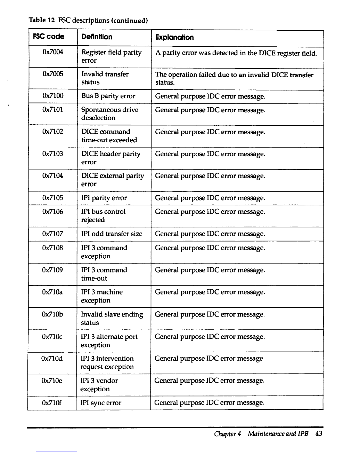
Table
12
FSC descriptions <continued)
FSCcode
Definition
Explanation
Ox7004
Register field parity
A parity error
was
detected
in
the DICE register field.
error
Ox.7005
Invalid transfer
The operation failed
due
to
an
invalid DICE transfer
status
status.
Ox7100
Bus B parity error
General purpose IDC error message.
Ox7101
Spontaneous drive
General purpose IDC error message.
deselection
Ox7102
DICE
command
General purpose IDC error message.
time-out exceeded
Ox7103
DICE header parity General purpose IDC error message.
error
Ox7104
DICE external parity General purpose IDC error message.
error
Ox7105
IPI parity error General purpose IDC error message.
Ox7106
IPI
bus
control General purpose IDC error message.
rejected
Ox7107
IPI
odd
transfer size General purpose IDC error message.
Ox7108
IPI 3
command
General purpose IDC error message.
exception
Ox7109
IPI 3
command
General purpose IDC error message.
time-out
Ox710a
IPI 3 machine General purpose JDC error message.
exception
Ox710b
Invalid slave
ending
General purpose IDC error message.
status
Ox710c
IPI 3 alternate
port
General purpose IDC error message.
exception
Ox710d
IPI 3 intervention General purpose
JDC
error message.
request exception
Ox710e
IPI 3
vendor
General purpose IDC error message.
exception
Ox710f
IPI sync error
General purpose JDC error message.
Chapter 4 Maintenance
and
IPB
43
Page 56

Table
12.
FSC
descriptions (continued)
FSCcode
Ox7110
Ox7111
Definttlon
Explanation
IPI 3 incomplete
General purpose IDC error message.
substatus
Failed
due
to
bad
General purpose error message from disc drive.
spot
on
media
Sector
errors
The
slip
command
in
idcfmt
is used to repair
header
CRC
or
data
ECC
errors.
If
a sector
in
the user
data
area
of
the disc is
slipped, this should be done with exclusive access to the disc.
Sectors in the topology
and
diagnostic areas require exclusive
access to the disc. A description
of
the topology
is
included
in
the idcfmt (10)
man
page in Appendix A.
When slipping a sector with
idcfmt
running from ConvexOS,
idcfmt
attempts to lock the disc
during
the slip operation.
The
file system containing the sector to
be
slipped
should
be
unmounted.
Fault symptom codes
(FSC)
are printed to the console
and
the
errlog upon detection of
an
error. The following list identifies
some of the
FSCs
that indicate a sector
or
sectors should be
slipped.
• Ox102c-Recoverable IDC ECC error
• Ox102d-Bad header (checksum)
• Ox1069-Recoverable drive ECC error
• Ox5003-Uncorrectable IDC ECC error
• Ox5008-Uncorrectable drive ECC error
Multiple occurrence of recoverable ECC errors
on
a single sector
should be slipped before they become unrecoverable ECC
errors.
In the following example,
idcfmt
is used to slip sector 6
of
track 5
on
cylinder
10
in the drive addressed as
unit
2, which
is
attached to port 0 of the IDC
in
CCU slot
0.
idcfmt
-d
0 O 2
slip
10 5 6
For additional information about the use
of
idcfmt,
refer to
the
idcfmt(lD) man page in Appendix A.
44
Elite
3
Disc
Drive
Service
Guide
Page 57

FSC
codes
reported
during
autoconf
The
autoconf
routine is executed during the boot process.
autoconf
attempts a probe
and
attach
on
each device identified
in the /ioconfig
file
on
the SPU disc. During the probe
and
attach
of
an
Elite 3 disc drive each sector
in
cylinder 0 is read.
If
an
Elite
3 has not been formatted with
idcfmt,
multiple errors are
reported. The
FSC
codes you may see include:
• Ox102d-Bad header CRC error
• Ox104f-Missed sync byte
• Ox2005-Unable to read topology
map
• Ox4003-Section invalid
• Ox6000-Buffer overrun
or
underrun
error
The
FSC
Ox102d
is also reported when the Elite 3 drive has been
formatted by the vendor with a format that is incompatible with
the
ConvexOS device driver.
WM
messages
When a disc in a redundant stripe fails,
VVM
checks to see
if
a
hot spare is available for the affected partitions.
If
so,
WM
reconstructs the data from that disc
on
the specified hot spare
device and continues operations.
Figure
18
shows the message printed by
WM
when
a disc
failure is detected.
Figure
18
WM
device failure message
/Failure:
device
/dev/dxxx
in
stripe
/dev/stx
failed
\.
After printing the device failure message to the console,
VVM
attempts to instruct the
vvmdaemon,
to begin the automatic
reconstruction process.
If
VVM
successfully contacts the
daemon,
and
the daemon is able to perform the reconstruction,
no
human
intervention is required.
Chapter 4 Maintenance
and
IPB
45
Page 58
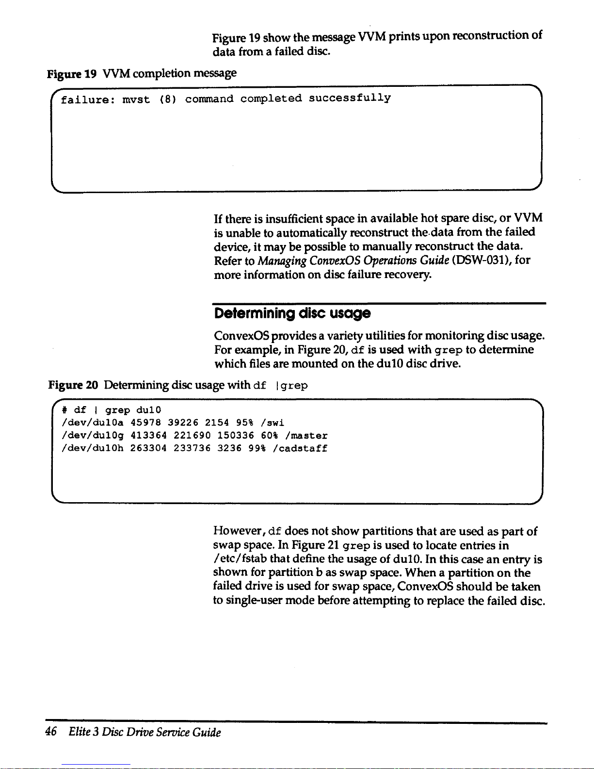
Figure
19
show the message
VVM
prints
upon
reconstruction
of
data from a failed disc.
Figure
19
VVM
completion message
r
failure:
mvst
(8) command
completed
successfully
If
there is insufficient space in available hot spare disc,
or
VVM
is unable to automatically reconstruct the.data from the failed
device, it may be possible to manually reconstruct the data.
Refer to
Managing
ConvexOS
Operations
Guide
(DSW-031), for
more information
on
disc failure recovery.
Determining
disc
usage
ConvexOS provides a variety utilities for monitoring disc usage.
For example, in Figure
20,
df
is used with
grep
to determine
which files are mounted
on
the dulO disc drive.
Figure
20 Determining disc usage with
df I grep
t
df I grep
dulO
/dev/dulOa
45978
39226
2154
95%
/swi
/dev/dulOg
413364
221690
150336
60%
/master
/dev/dulOh
263304
233736
3236
99%
/cadstaff
However,
df
does not show partitions that are used
as
part
of
swap space. In Figure
21
grep
is used to locate entries
in
/etc/fstab
that define the usage of dulO. In this case
an
entry
is
shown for partition b as swap space. When a partition
on
the
failed drive is used for swap space, ConvexOS should
be
taken
to single-user mode before attempting to replace the failed disc.
46
Elite 3 Disc
Drive
Service
Guide
Page 59
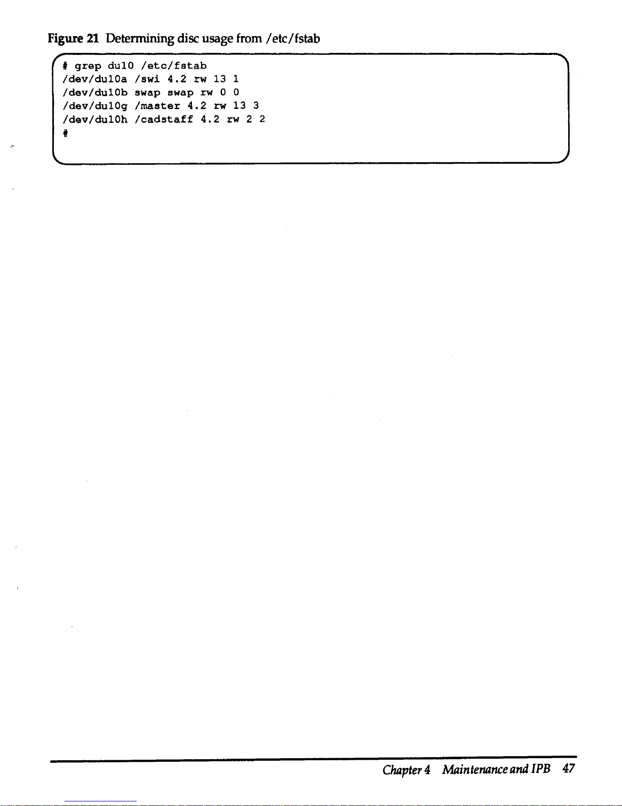
Figure
21
Determining disc usage from /etc/fstab
#
grep
dulO
/etc/fstab
/dev/dulOa
/swi
4.2
rw
13
1
/dev/dulOb
swap
swap
rw
0 0
/dev/dulOg
/master
4.2
rw
13
3
/dev/dulOh
/cadstaff
4.2
rw
2 2
*
Chapter 4 Maintenance
and
IPB
47
Page 60

Removal and
replacement
procedures
Caution
Step 1
Step2
Step3
Step4
Steps
Step 1
Step2
Step3
Step4
Components in the Elite 3 chassis cannot
be
serviced while
the
chassis is installed
in
a peripheral cabinet.
Elite 3 chassis
To
remove
an
Elite 3 chassis from a peripheral cabinet:
Use appropriate electrostatic discharge protections procedures
as
described in the Preface, "Electrostatic discharge protection."
As
root,
use
the
/etc/ahutdown
command
to
halt ConvexOS
before
removing
power
from
an
Ellte 3 disc
drive
Lmed
In
the
ConvexOS
ftle
system.
Fallure
to
do
so
may cause a
system
crash
and
loss
of data.
Tum
the power switch
on
the
rear of the Elite 3 chassis off.
Disconnect
IPI cable(s)
and
terminator.
Loosen rear alignment/retaining screw.
Remove front alignment/ retaining screw.
Remove the Elite 3 chassis from
the
disc drive tray.
Reverse the procedure to install
an
Elite 3 chassis.
Disc
drive
With the Elite 3 chassis
on
a grounded work area,
perform
the
following steps to remove
an
Elite 3 disc
drive
from
the
Elite 3
chassis:
Loosen screws
on
the Elite 3 chassis cover
and
remove
the
cover.
Disconnect the
IPI interface cable, operator panel cable,
and
power
supply cable.
Remove the two
upper
mounting screws
on
the
top
of
the
upper
disc mounting bracket.
Remove the two lower mounting screws from the
lower
disc
mounting bracket. Lower bracket mounting screws
are
accessed
through holes
on
the side of the Elite 3 chassis.
Reverse the procedure to install
an
Elite 3 disc drive
in
an
Elite 3
chassis.
48
Elite 3 Disc
Drive
Service
Guide
Page 61

Step
1
Step2
Step
3
Step4
Step
1
Step
2
Step
3
Step4
Power
supply
With the Elite 3 chassis
on
a grounded
work
area, perform the
following steps to remove the power supply from the Elite 3
chassis:
Loosen screws on the Elite 3 chassis cover
and
remove the cover.
Disconnect the
ac
cable from
Jl
on
the power supply.
Disconnect the de power cable from
J2
on
the power supply.
Remove the 4 mounting screws. Mounting screws are accessed
through holes on the side of the Elite 3 chassis.
Reverse the procedure to install the power supply in
an
Elite 3
chassis.
Operator panel
With the Elite 3 chassis
on
a grounded
work
area, perform the
following steps to remove the operator panel from the Elite 3
chassis:
Loosen screws on the Elite 3 chassis cover
anq
remove the cover.
Remove the power supply.
Disconnect the operator panel cable from the Elite 3 disc drive.
Make note of the cable routing for subsequent installation as
shown
in
Figure
22.
Remove mounting screws
and
operator panel.
Reverse the procedure to install
an
operator panel
in
the Elite 3
chassis.
Chapter 4 Maintenance
and
IPB
49
Page 62

Figure 22 Elite 3 operator panel cable routing
Step 1
Step2
Step3
Step4
Fan
assembly
AH261010
4/8/93
With the Elite 3 chassis
on a grounded
work
area,
perform
the
following steps to remove the fan from
the
Elite 3 chassis:
Loosen screws
on
the Elite 3 chassis cover
and
remove
the
cover.
Remove the power supply.
Remove the
power
cable from the fan assembly.
Remove the mounting screws while holding
the
fan.
Reverse the procedure to install a fan in
an
Elite 3 chassis.
50
Elite 3 Disc
Drive
Service
Guide
Page 63
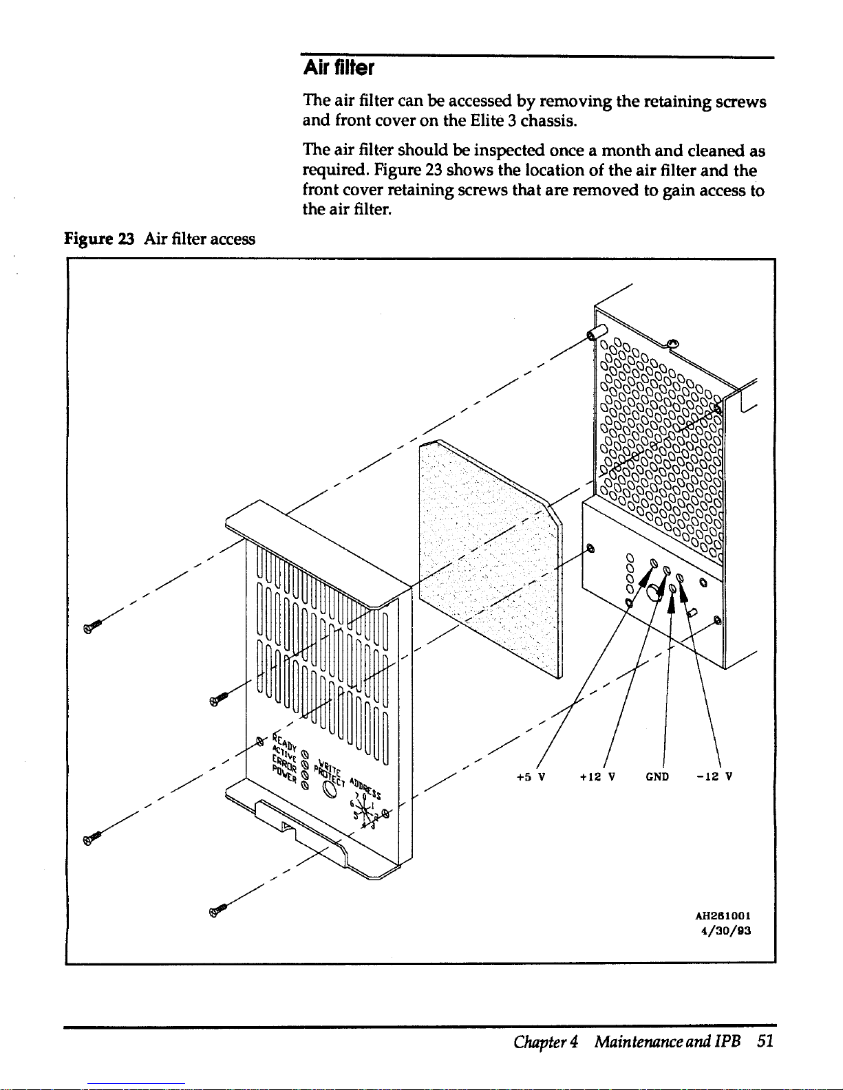
FigUl'e
23
Air filter access
Air
filter
The air filter can be accessed
by
removing the retaining screws
and
front cover on the Elite 3 chassis.
The air filter should be inspected once a
month
and
cleaned as
required. Figure
23
shows the location of the air filter
and
the
front cover retaining screws that are removed to gain access to
the air filter.
+12 v
GND
-12
V
AH261001
4/30/93
Chapter 4 Maintenance
and
IPB
51
Page 64
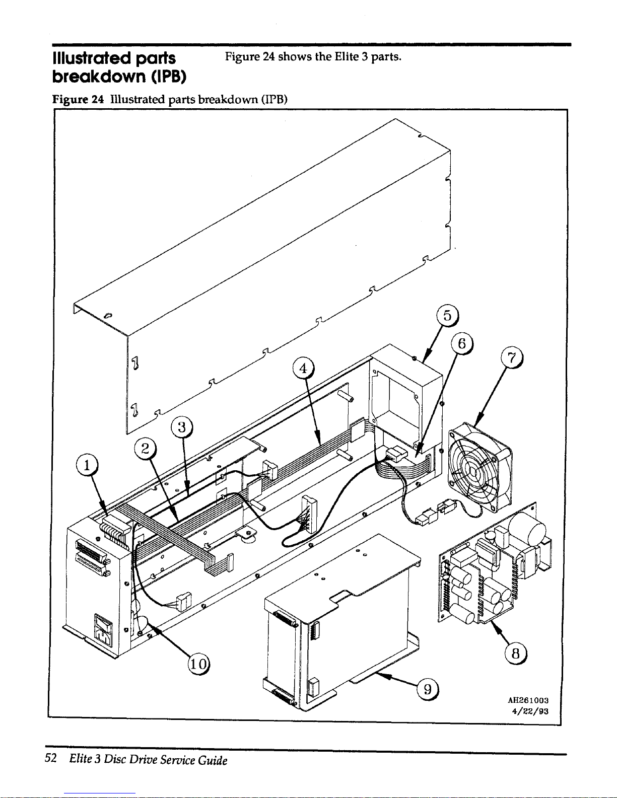
Illustrated
parts
breakdown
(IPB)
Figure
24
shows the Elite 3 parts.
Figure 24 Illustrated parts breakdown
(IPB)
52
Elite 3 Disc
Drive
Service
Guide
AH261003
4/22/93
Page 65

Table
13
contains
the
CONVEX
part
numbers
for
the
FR Us
found
in
an
Elite 3 chassis. The CONVEX
part
number
for
the
entire
assembly is
550-002230-200.
Figure 25
IPB
parts list
Item
CONVEX
part
Description
number
number
1
601-500059-200
Internal
data
cable
2
603-070010-200
de
cable harness
3
603-030042-200
ac cable
harness
4
601-160004-200
Drive to
operator
panel
5
312-000555-001
Air
filter1
6 411-001385-200
Operator
panel
2
7 500-000544-200 Fan assembly
8
200-001046-200
Power
supply
9
204-00026-200 Elite 3 2
HP
3.4 Gbyte
disc
drive
10 603-010029-200
Ground
strap
1
Item 5 in Figure
24
points to the general area where the
air
filter is located.
The
air filter is shown in Figure
23.
2
Item 6 in Figure
24
points to the general area where the operator panel
is
located.
Chapter 4 Maintenance and IPB 53
Page 66
idcfmt ( 1 D)
man
page
IDCFMT(10)
NAME
CONVEX
Diagnostic
Utilities
Manual
idcfmt
idcfmt
- utility for JDC
disk
formatting,
media
repair,
and
data
editing
SYNOPSIS
idcfmt
-d ccu
port
unit
[options] [commands]
or
id
cf
mt
-d I
dev
I rdun-ctl [options] [commands]
A
IDCFMT(tD)
Idcfmt
is a program
used
to prepare
and
repair
an
IDC
disk
for
use
under
ConvexOS.
There are
two
versions of idcfmt. The first version
runs
on
the
Service Processor
while
ConvexOS is
not
running.
The second version
runs
on
CONVEX
C200/C3200/C3400/C3800
Series machines while ConvexOS
is
running.
Both versions
require
the
user
invoking
the
program
be
the superuser.
Idcfmt
is
invoked
by
typing
its name, a "-d", followed
by
the
CCU
slot
number,
IPI
port
number,
and
drive
unit
number
of the drive to
be
used.
The
ConvexOS
version
allows
a
drive
to
be
specified
through
its control name,
such
as
/dev/rduO-ctl
or
/dev/rdu1-ctl.
A list of
options
may
follow
the
drive
specification,
then
zero
or
more
commands.
If
no
commands
are
given
on
the
command
line,
idcfmt
displays a
prompt
and
expects
the
commands
to
be
entered
from the
standard
input.
OPTIONS
With
the
exception
of
the -v option, the following
options
are
not
normally
required.
These
options
are
intended
for
use
under
rare, exceptional conditions
and
then
only
by
CONVEX personnel. The description for the following
options
make
reference to
various
files
used
by
idcfmt. A description of the layout
of
these files
may
be
found
at
the
end
of
this document.
-t
dkd-999
The
-t
option
overrides
the
automatic identification
of
the
disk
drive
that
idcfmt
normally
performs.
If
the
-t
option
is
not
specified,
idcfmt
queries
the
target
disk
drive
for
its
model
number. This
model
number
is
then
used
as
a search
key
in
the file
/mnt/usr/lib/DB_idc.
Idcfmt
uses the
matching
entry
in
this
file to
Appendix
A
idcfmt
(1D)
man
page
55
Page 67
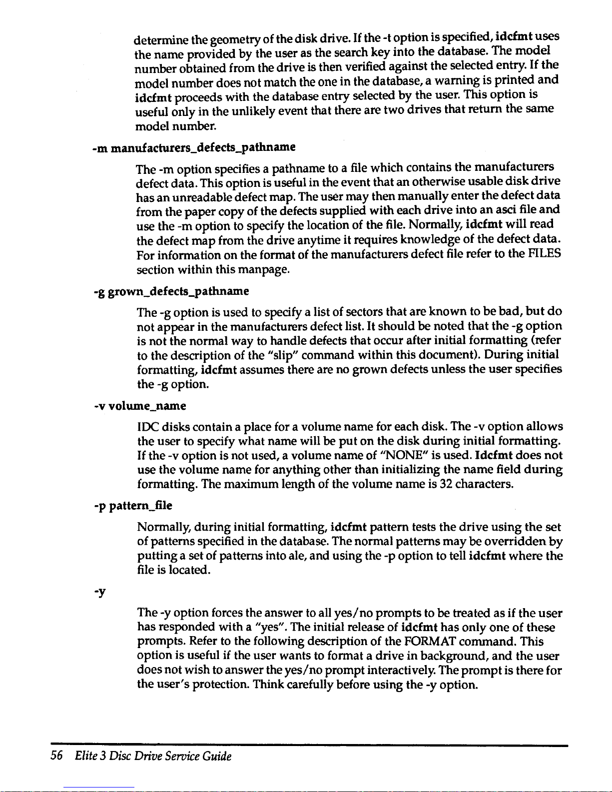
determine the geometry of the disk drive.
If
the -t option is specified,
idcfmt
uses
the name provided by the user as the search key into the database. The
model
number obtained from the drive is then verified against the selected entry.
If
the
model number does not match the one in the database, a warning is printed
and
idcfmt proceeds with the database entry selected
by
the user. This option is
useful only in the unlikely event that there are two drives that return the same
model number.
-m
manuf
acturers_defects_pathname
The -m option specifies a pathname to a file which contains the manufacturers
defect data. This option is useful in the event that
an
otherwise usable
disk
drive
has
an
unreadable defect map. The user may then manually enter the defect
data
from the
paper
copy of the defects supplied with each drive into
an
asci file
and
use the -m option to specify the location of the file. Normally, idcfmt will read
the defect
map
from the drive anytime it requires knowledge of the defect
data.
For information
on
the format of the manufacturers defect file refer to the FILES
section within this manpage.
-g grown_defects_pathname
The -g option is used to specify a list of sectors that are
known
to
be
bad,
but
do
not appear in the manufacturers defect list.
It
should be noted that the
-g
option
is not the normal way to handle defects that occur after initial formatting (refer
to the description of the
"slip" command within this document). During initial
formatting, idcfmt assumes there are no grown defects unless the
user
specifies
the -g option.
-v volume_name
IDC disks contain a place for a volume name for each disk. The -v option allows
the user to specify what name will be
put
on
the disk
during
initial formatting.
If
the -v option is not used, a volume name of ''NONE" is used.
Idcfmt
does
not
use the volume name for anything other than initializing the name field
during
formatting. The maximum length of the volume name is 32 characters.
-p pattern_file
-y
Normally, during initial formatting, idcfmt pattern tests the drive using
the
set
of patterns specified in the database. The normal patterns
may
be
overridden
by
putting a set of patterns into ale,
and
using the -p option to tell
idcfmt
where
the
file is located.
The -y option forces the answer
to
all
yes/no
prompts to be treated as
if
the
user
has responded with a "yes". The initial release of idcfmt has only one
of
these
prompts. Refer to the following description of the
FORMAT command. This
option is useful if the user wants to format a drive in background,
and
the user
does not wish to answer the
yes/no
prompt interactively. The
prompt
is there for
the
user's
protection. Think carefully before using the -y option.
56
Elite 3 Disc
Drive
Seroice
Guide
Page 68

COMMANDS
The following commands perform various functions
on
IDC disks. Each
command
is
listed along
with
any
required arguments specific to that command. Some
commands
require exclusive access to the disk. The description for each command lists whether
or
not the command requires exclusive access. The version
of
idcfmt
that
runs
on
the
Service Processor automatically assumes that it has exclusive access to
the
disk. The
version of
idcfmt
that
runs
under
the ConvexOS coordinates exclusive access to the
disk
through a diagnostic ioctl() call to the ConvexOS disk driver. Exclusive access to a
disk
is
denied
if
the disk is currently
in
use
under
the ConvexOS file system,
or
if
any
process
has
opened
any
of the block
or
character special devices associated
with
the
disk.
The description for some of the commands assume that the
user
has
a basic knowledge
of the layout of
an
IDC disk. A description of this layout follows below.
format
Formats the drive
if
it
appears that the drive
has
not
been
previously formatted.
If
the drive
appears
to be partially formatted, the format resumes
at
the
appropriate point. This command will destroy
any
previous
data
on
the
disk.
Exclusive access to the disk is required before this command can execute. This
command tries to determine whether
or
not the drive is formatted
by
attempting
to read the topology
map
in the topology area.
If
successful in reading the
topology map, the command prints a message
and
proceeds to
the
format
verification step. The user
may
override this behavior
by
using the FORMAT
command which is the next command described.
If
the
topology
map
is
unreadaple, the program assumes that the drive has not been completely
formatted.
It
then proceeds to check for a partial format of
the
disk
by
looking for
checkpoint
data
in the topology and diagnostic areas.
If
a valid set
of
checkpoint
data
is found, the command resumes formatting
at
the point specified
by
the
checkpoint data.
If
no
checkpoint
data
is found, the command assumes that the drive
has
never been
formatted
and
proceeds to format the drive accordingly. The steps required to
format a drive are:
o) Identify the type of drive being formatted
by
performing a read configuration
command to the drive. The data returned by the read configuration
command
is
used
to search the
data
base file "DB_idc" for a match. The
data
base file contains
information
about
the disk drive such as number of cylinders,
number
of
tracks,
encoding schemes, etc. The user may override this automatic identification of the
drive
by
using the -t option
on
the command line.
o) Read the manufacturers defect
data
from the drive. The
user
may
override this
step
by
using
the
-m
option described previously in the OPTIONS section.
o) Assume that there are no grown defects for the drive. The
user
may
override
this step
by
using the -g option described previously in the OPTIONS section.
o) Format the topology area with
no
spare sectors. The topology area is
then
pattern tested with a set of patterns that are specified in the
data
base file
"DB _idc". The user
may
override the normal patterns
by
specifying
the
-p
option
Appendix A
idcfmt
(1D)
man
page
57
Page 69

on
the
command line. Once pattern testing is complete,
the
topology area
is
re-formatted
with
the
number of spare sectors specified in the
data
base file
"DB_idc". A detailed description of pattern testing can
be
found
in:
the
FILES
section of this manpage.
o) Format the user, diagnostic, and spare areas
of
the disk with
no
spares.
The
first checkpoint of
the
format is written this step is complete.
o) Pattern test
the user, diagnostic,
and
spare areas of
the
disk
with
the
patterns
specified
in
the
data
base file "DB_idc". The
user
may
override
the
normal
patterns
by
use
of
th~
-p
option described previously
in
the
OPTIONS section.
The process of pattern testing consists of writing each of
the specified
patterns
to
the
area
under
test,
and
then reading each pattern to look for errors
that
might
be
attributed to disk media problems. These include
data
Error Correcting
Code
(ECC) errors, header Cyclical Redundancy Character (CRC) errors,
and
missing
sector sync byte errors.
If
any of these errors are encountered,
the
manufacturers
defect list is searched to see if the cylinder, track
and
sector where
the
error
occurred is already listed.
If
the cylinder, track,
and
sector is
not
in
the
manufacturers defect list, the grown defect list is
then
searched.
If
the
cylinder,
track,
and
sector where the error occurred is
not
found
in
either defect list,
the
location is
added
to
the
grown defect list. After each
pattern
is completed, a
checkpoint
is
written to the disk.
o) Format
the
user, diagnostic,
and
spare areas
of
the disk, reserving a
number
of
sectors
at
the
end
of each cylinder for
use
as
spare sectors.
Any
sector
which
is
listed
in
either
the
manufacturers
or
grown defect lists is re-allocated from
this
pool of spare sectors.
If
the number of defective sectors
in
a cylinder exceeds
the
number
of spare sectors allowed for each cylinder,
the
disk
is
not
usable
under
ConvexOS. A checkpoint is written to the
disk
after this step.
o) Initialize the topology area by writing several copies
of
the topology data. This
includes the topology area map, the defect lists for
the
disk, a copy of
the
disks
geometries, the ConvexOS label, etc. The contents of
the
topology area
is
described below.
o) Clear
the
diagnostic cylinder.
o) Verify that the drive received a valid format. Refer to
the
verify
command
below for a description of what steps are taken to verify
that a drive
is
formatted
correctly.
The
disk
in
now
formatted
and
ready for use.
FORMAT
Formats the drive regardless of its current state. This
command
is
the
same
as
the
format command listed above, except that
if
the
disk
is
determined
to
have
a
valid, complete disk format, the user is
prompted
as
to whether
or
not
to
continue.
If
the user answers in the affirmative,
the
format operation proceeds
as
if
the
drive
had
never been formatted.
If
no
valid format is found
on
the
drive,
this command does not look for checkpoint data. The format starts from
the
58
Elite
3
Disc
Drive
Service
Guide
Page 70
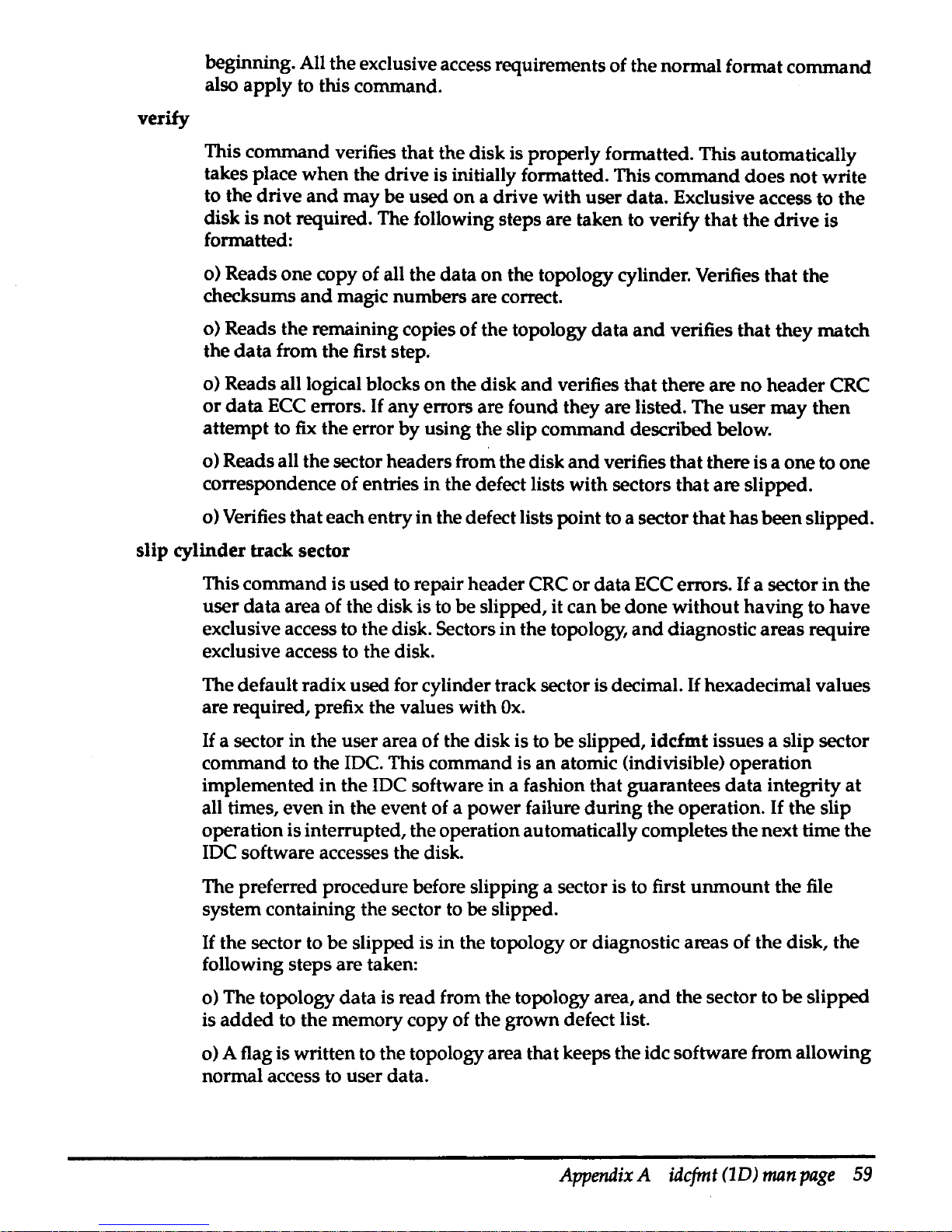
verify
beginning. All the exclusive access requirements of the normal format command
also apply to this command.
This command verifies that the disk is properly formatted. This automatically
takes place when the drive is initially formatted. This command does
not
write
to the drive
and
may be used
on
a drive with user data. Exclusive access to the
disk is not required. The following steps are taken to verify that the drive is
formatted:
o) Reads one copy of all the data on the topology cylinder. Verifies that the
checksums
and
magic numbers are correct.
o) Reads the remaining copies of the topology
data
and
verifies that they match
the
data
from the first step.
o) Reads all logical blocks
on
the disk
and
verifies that there are
no
header CRC
or
data
ECC
errors.
If
any errors are found they are listed. The user
may
then
attempt to
fix
the error by using the slip command described below.
o) Reads all the sector headers from the disk
and
verifies that there is a one to one
correspondence of entries
in
the defect lists with sectors that are slipped.
o) Verifies that each entry
in
the defect lists point to a sector that
has
been slipped.
slip cylinder track sector
This command is used to repair header CRC or data ECC errors.
If
a sector
in
the
user
data
area of the disk is to be slipped, it can be
done
without having to have
exclusive access to the disk. Sectors in the topology,
and
diagnostic areas require
exclusive access to the disk.
The default radix used for cylinder track sector is decimal.
If
hexadecimal values
are required, prefix the values with
Ox.
If
a sector in the user area of the disk is to be slipped, idcfmt issues a slip sector
command to the
IDC. This command is
an
atomic (indivisible) operation
implemented
in
the IDC software in a fashion that guarantees
data
integrity at
all times, even in the event of a power failure
during
the operation.
If
the slip
operation is interrupted, the operation automatically completes the next time
the
IDC software accesses the disk.
The preferred procedure before slipping a sector is to first
unmount
the file
system containing the sector to be slipped.
If
the sector to be slipped is in the topology or diagnostic areas of the disk, the
following steps are taken:
o) The topology data is read from the topology area,
and
the sector to
be
slipped
is
added
to the memory copy of the grown defect list.
o) A flag is written to the topology area that keeps the idc software from allowing
normal access to user data.
Appendix
A
idcfmt
(1D)
man
page
59
Page 71

o)
If
the sector to
be
slipped is not
in
the topology area, then the cylinder
that
contains the sector is reformatted, causing the specified sector to be reallocated
from the pool of spare sectors at the end of the cylinder.
o)
If
the sector to be slipped is in the topology area, then the diagnostic area is
reformatted in order to ensure that the topology area
data
can
be
written to
the
disk.
o)
If
the sector to be slipped is in the topology area, a checkpoint containing
the
topology data is written to the diagnostic area.
o) If the sector to be slipped is in the topology area, the topology area is
reformatted
and
the data is copied from the diagnostic area back to the topology
area. The diagnostic area is then reformatted to remove the checkpoint data.
o)
If
the sector to be slipped is not
in
the topology area, the defect lists
in
the
topology area are updated to show the new defect data.
o) The flag which keeps the IDC microcode from allowing access to
user
data
is
removed.
If
a slip
of
a sector in the topology
or
diagnostic areas is interrupted, the
user
data
on
the disk is not accessible until the slip is completed. The completing
of
the slip
is accomplished
by
re-issuing the slip command with the same parameters
as
before.
If
the parameters differ after
an
interruption,
idcfmt
prints
out
a message
stating
what
sector was being slipped before the interruption.
unslip
cylinder track sector
This command is the inverse of the slip command described above.
It
is
provided
in
the event that user mistyped the cylinder track
and
sector
number
during
a
slip command,
or
to allow the user to slip
and
then unslip a sector
in
an
attempt
to
fix
a header CRC
or
data
ECC
error. As with the slip command, the
unslip
command does not require exclusive access to the disk
if
the sector to
be
unslipped is in the user data area.
If
the sector to be unslipped is in the topology
or
diagnostic areas, exclusive access to the disk is required. The algorithm
used
by
the unslip command is identical to the one used for the slip command, except
that the specified sector is removed from the defect list instead of being
added
to
it.
WARNING!!!!
UNSLIPING A SECTOR FOR
ANY
REASON OTHER THAN THOSE
DESCRIBED
ABOVE
MAY
RESULT
IN CATASTROPHIC AND
UNRECOVERABLE
LOSS
OF
DATA
ON
THE ENTIRE
DISK.
60
Elite 3 Disc
Drive
Service
Guide
Page 72

EXAMPLES
idcfmt -d 2 0 1 format
THIS
IS
AN
EXAMPLE
OF HOW
TO
FORMAT
99%
OF
ALL
DRIVES. Formats
drive
1,
on
port
0,
of ccu 2 if the drive has never been formatted.
If
a partial
format is found, the format resumes
at
the appropriate point, with the
manufacturers
and
grown defect lists that were in effect
when
the format was
interrupted.
If
the drive has no valid format
on
it, then
the
program reads the
manufacturers defect data from the drive.
The examples that follow are for drives with unreadable manufacturers defect
lists or other peculiarities.
If
a drive develops additional defects after it has been
formatted, they may be fixed with the slip command described above.
idcfmt-d
/dev/rdul-ctl
format
Formats the drive pointed to by
/dev/rdu1-ctl.
Everything else is the same as
in
the
first example.
idcfmt -d 2
0 1 -m foo format
Formats the same as the first example, but the user specified defect list
in
the file
"foo" is used instead of reading the manufacturers supplied list
on
the disk
drive.
idcfmt -d 2
0 1
FORMAT
Forces a format operation to occur regardless of the current status of
the
drive.
The manufacturers defect cylinder is read
and
no grown defect
data
is assumed.
idcfmt -d 2
0 1 -m foo FORMAT
Formats the same as the previous example,
but
the user specified defect list in the
file "foo" is used instead of reading the manufacturers supplied list
on
the disk
drive.
idcfmt -d 2 0 1 verify
Causes a verification of the format of the disk. The steps taken to verify the disk
are described previously.
idcfmt -d 2
0 1 slip
10
5 6
Causes sector 6 of track 5 on cylinder
10
to be re-allocated from the pool of spare
sectors
at
the end of the disk.
idcfmt -d 2
0 1 unslip
10
5 6
This command undoes the effects of the command described
in
the previous
example.
PLEASE read the description of the slip
and
unslip command before
using the unslip command.
Appendix A idcfmt
(1D)
man
page
61
Page 73

LAYOUT
OF
AN
IDC
DISK
An IDC disk has five distinct areas. They are:
1)
The
topology
area
2)
The
user
data
area
3)
The
diagnostic
area
4) A
spare
area
5)
The
manufacturers
supplied
defect
data
Each area is immediately adjacent to each other and they occur in the order listed above.
Each area must begin and end on a cylinder boundary. The size of each area is
determined
by
idcfmt during the initial format of the disk from the
data
contained
in
the
database. Refer to the section on
FILES
within this
man
page for more information.
The topology area contains various types of information about the disk. Each section
in
the topology area is recorded in triplicate. The topology area is recorded
in
the default
geometry specified
by
the manufacturer. The other areas are recorded
in
a format
specified
by
CONVEX.
The various sections
in
the topology area are:
a) A map of the rest of the topology area (always located
at
logical block 0)
b) A copy of the manufacturers defect data. This
data
is used to avoid reading
or
writing sectors with defects in them. The defect
data
is also
used
in calculating
what the sector header each sector contains. The disk is unreadable if this
data
is
not present.
c)
The grown defect data. This list of defects performs the same function
as
the list
in
"b" above, except that it contains a record of defects that were
not
listed
in
the
manufacturers list.
d) A copy of the CONVEX specified disk geometry used in the other areas of the
disk.
e) A copy of the manufacturers default geometry.
f)
The ConvexOS disk label. This disk label contains the type of the disk, e.g.
DKD-502, the volume name, e.g. Volume_123, the
date
that the drive
was
formatted, the date the ConvexOS disk label was last changed,
and
a list of
the
logical partitions defined for the drive.
g) Two scratch areas used by the
IDC
software to keep track of the state of a sector
slip operation in the user data area. These areas are interrogated
when
the JDC
software is first booted.
If
the scratch areas indicate that a slip
or
unslip of a
sector in the user area was in progress
but
was interrupted, then the operation
automatically resumes at the interrupted point.
H the scratch areas indicate that
an
exclusive access diagnostic operation was in progress, the IDC software will
not allow access to the user data area until the operation is finished.
62
Elite 3 Disc
Drive
Service
Guide
Page 74
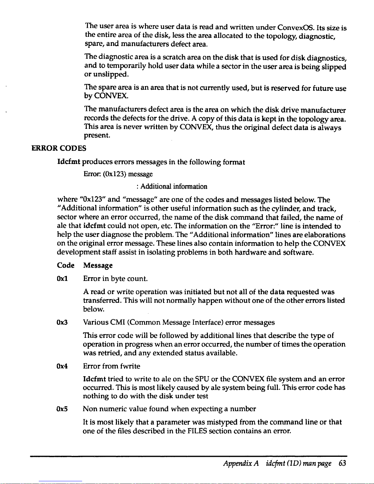
The
user
area is where user
data
is read
and
written
under
ConvexOS. Its size
is
the entire area of the disk, less the area allocated to
the
topology, diagnostic,
spare,
and
manufacturers defect area.
The diagnostic area is a scratch area
on
the
disk
that
is
used
for
disk
diagnostics,
and
to temporarily hold
user
data
while a sector
in
the
user
area is being
slipped
or
unslipped.
The
spare
area is
an
area
that
is not currently used,
but
is reserved for future
use
by
CONVEX.
The manufacturers defect area is
the
area
on
which
the
disk
drive
manufacturer
records
the
defects for the drive. A copy of this
data
is
kept
in
the
topology area.
This area is never written
by
CONVEX,
thus
the original defect
data
is
always
present.
ERROR CODES
Idcfmt
produces errors messages in the following format
Error:
(Ox123)
message
: Additional infonnation
where
"Ox123"
and
"message" are
one
of the codes
and
messages listed below. The
"Additional information" is other useful information such
as
the
cylinder,
and
track,
sector where
an
error occurred, the name of the disk command
that
failed,
the
name
of
ale that
idcfmt
could
not
open, etc. The information
on
the
"Error:" line
is
intended
to
help the
user
diagnose the problem. The "Additional information" lines are elaborations
on
the
original error message. These lines also contain information to
help
the
CONVEX
development staff assist
in
isolating problems
in
both
hardware
and
software.
Code Message
Oxl Error
in
byte
count.
A read
or
write operation was initiated
but
not
all of
the
data
requested
was
transferred. This will
not
normally
happen
without one
of
the
other
errors listed
below.
Ox3
Various CMI (Common Message Interface) error messages
This error code will
be
followed
by
additional lines
that
describe the
type
of
operation in progress
when
an
error occurred,
the
number
of
times
the
operation
was
retried,
and
any
extended status available.
Ox4
Error from fwrite
Idcfmt
tried to write to ale
on
the SPU
or
the CONVEX file system
and
an
error
occurred. This is most likely caused
by
ale system being full. This error code
has
nothing to
do
with
the disk
under
test
OxS
Non
numeric value found
when
expecting a
number
It is
most
likely that a
parameter
was mistyped from
the
command
line
or
that
one of
the
files described
in
the
FILES
section contains
an
error.
Appendix A idcfmt
(1D)
man
page
63
Page 75
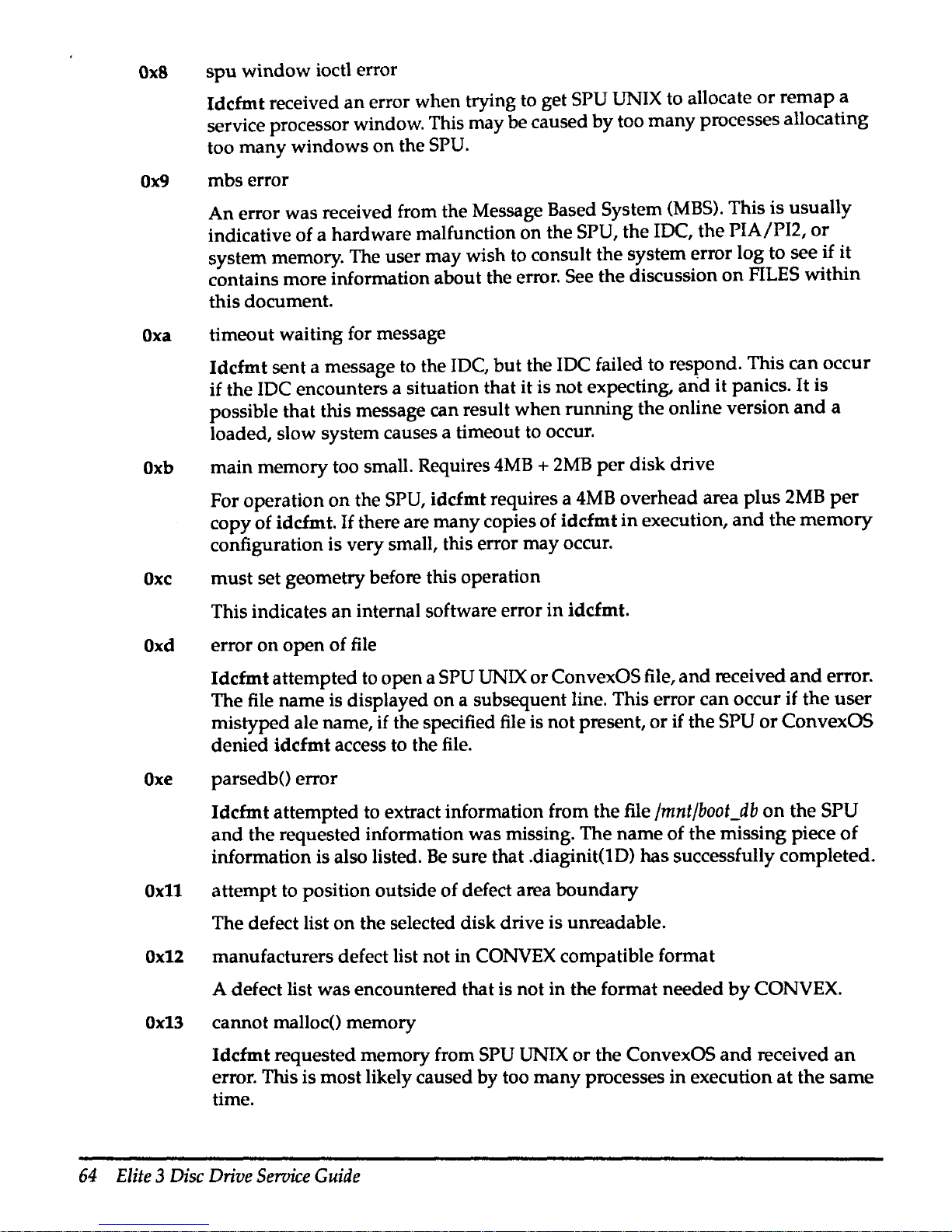
Ox8
spu
window
ioctl error
Idcfmt
received
an
error when trying to get SPU UNIX to allocate
or
remap
a
service processor window. This may be caused
by
too
many
processes allocating
too
many
windows
on
the SPU.
Ox9
mbs
error
An
error was received from the Message Based System
(MBS).
This
is
usually
indicative of a hardware malfunction
on
the SPU,
the
lOC,
the
PIA/Pl2,
or
system memory. The user
may
wish to consult the system error
log
to see
if
it
contains more information about the error. See
the
discussion
on
FILES
within
this document.
Oxa
timeout waiting for message
Idcfmt
sent a message to the IDC,
but
the JDC failed to respond. This
can
occur
if the JDC encounters a situation that it is not expecting,
arid
it
panics.
It
is
possible that this message can result
when
running
the
online version
and
a
loaded, slow system causes a timeout to occur.
Oxb
main memory too small. Requires
4MB + 2MB
per
disk drive
For operation
on
the SPU,
iddmt
requires a
4MB
overhead area
plus
2MB
per
copy of idcfmt.
If
there are many copies of
idcfmt
in
execution,
and
the
memory
configuration is very small, this error may occur.
Oxc
must
set geometry before this operation
This indicates
an
internal software error
in
idcfmt.
Oxd
error
on
open
of file
Idcfmt
attempted to open a SPU UNIX
or
ConvexOS file,
and
received
and
error.
The file name is displayed
on
a subsequent line. This error can occur if
the
user
mistyped ale name, if the specified file is not present,
or
if
the
SPU
or
ConvexOS
denied idcfmt access to the file.
Oxe
parsedb() error
Idcfmt
attempted to extract information from
the
file
/mnt/boot_db
on
the
SPU
and
the
requested information was missing. The
name
of
the
missing piece
of
information is also listed.
Be
sure that .diaginit(lD)
has
successfully completed.
Ox11
attempt to position outside
of
defect area
boundary
The defect list
on
the selected disk drive is unreadable.
Ox12
manufacturers defect list not in CONVEX compatible format
A defect list was encountered that is not
in
the format
needed
by
CONVEX.
Ox13
cannot malloc() memory
Idcfmt
requested memory from SPU UNIX
or
the ConvexOS
and
received
an
error. This is most likely caused by too many processes
in
execution
at
the
same
time.
64
Elite
3
Disc
Drive
Service
Guide
Page 76

Ox14,0x15
Set
#1
missing from defect map
Last set in
map
does not have proper value
in
flag field These errors indicate that
the defect
map
on the drive has been partially destroyed,
and
is not usable.
Ox16
must read defects before this operation
This is
an
internal software error in idcfmt. Contact the CONVEX development
staff to report a software error.
Ox17
error from fseek()
Idcfmt tried to re-position ale and received
an
error.
Ox18
defect file differs
on
pass2 during reading mfg defects.
Ox19
data miscompare
Idcfmt
was
comparing data read from the disk with
known
good
data
and
it
encountered a discrepancy. The address of the
data
along with the expected
and
actual data is displayed.
Oxlc
topology area too small
The topology area is too small to hold the required data. Make sure that the
correct diagnostic database is installed. This error is most likely caused
by
attempting to format a drive with the wrong parameter specified
in
the -t option
on
the command line.
Oxtd magic number incorrect
Oxte topology check
sum
incorrect
These errors indicate corruption of the topology area.
Ox2e
Illegal ecc interleave
An
unknown
ECC interleave was specified
in
the database file. Make sure the
correct version of system diagnostics and diagnostic database are installed.
Ox2f
error from fread
ldcfmt
tried to read ale
on
the SPU UNIX or ConvexOS file system
and
received
an
error.
Ox30
Bad format for manufacturers defect
The user specified the -m option and one of the entries
in
the file is incorrect. The
line
number
of the entry in error is also displayed.
Ox31
Manufacturers defect overlap. List not usable
The manufacturers defect data contains overlapping defect entries. This is not a
normal occurrence
and
idcfmt can not handle this case.
Ox37
Cmd
line DKD entry not unique in
DB
file
Appendix A idcfmt
(1D)
man
page
65
Page 77
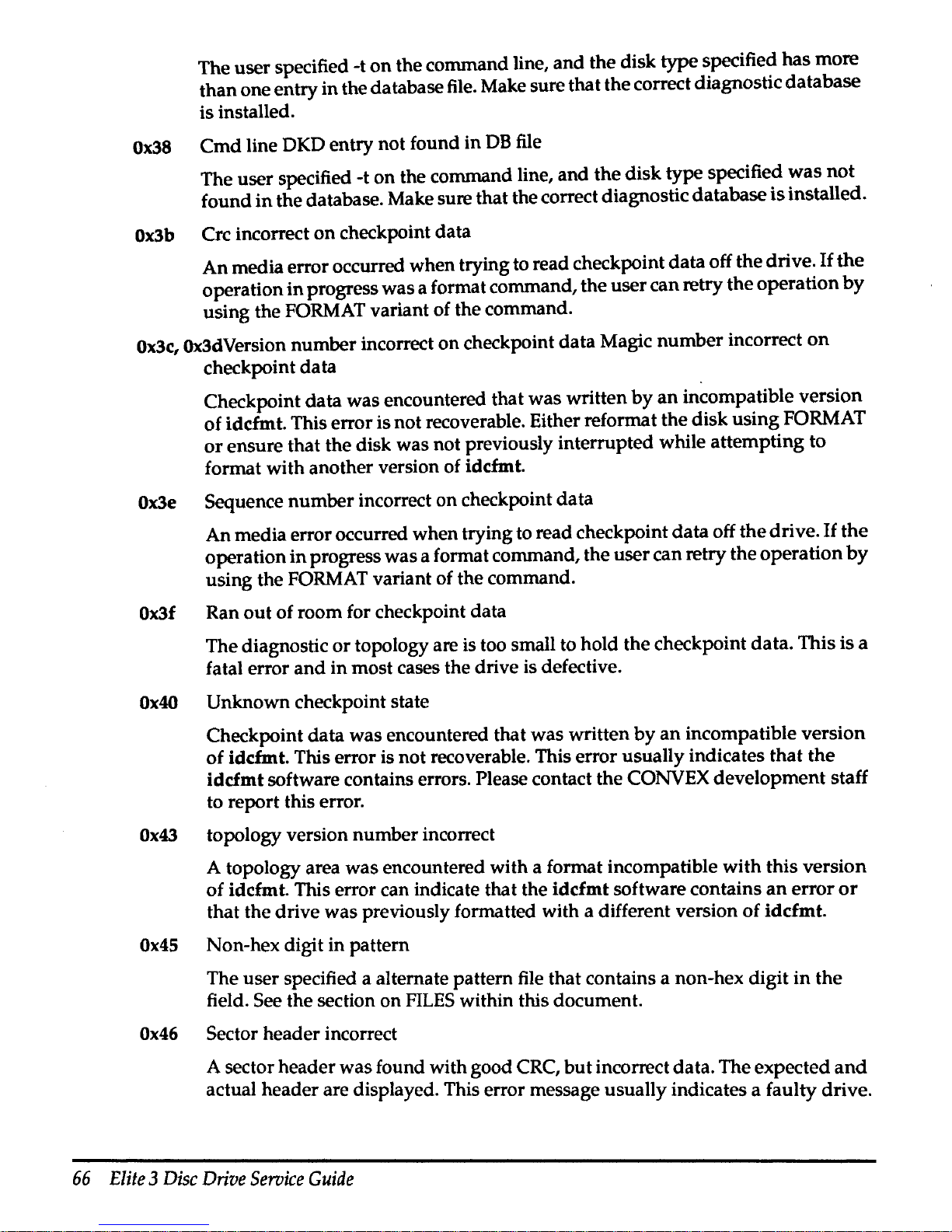
The user specified -t
on
the command line, and the disk type specified has more
than one entry in the database
file.
Make sure that the correct diagnostic database
is installed.
Ox38
Cmd
line DKD entry not found in
DB
file
The user specified -t on the command line, and the disk type specified
was
not
found
in
the database. Make sure that the correct diagnostic database
is
installed.
Ox3b
Crc incorrect
on
checkpoint data
An media error occurred when trying to read checkpoint data off the drive.
If
the
operation
in
progress was a format command, the user can retry the operation
by
using the
FORMAT
variant of the command.
Ox3c,
Ox3dVersion number incorrect on checkpoint data Magic number incorrect
on
checkpoint data
Checkpoint data was encountered that was written
by
an
incompatible version
of idcfmt. This error is not recoverable. Either reformat the disk using
FORMAT
or
ensure that the disk was not previously interrupted while attempting to
format with another version of idcfmt.
Ox3e
Sequence number incorrect on checkpoint data
An media error occurred when trying to read checkpoint data off the drive.
If
the
operation
in
progress was a format command, the user can retry the operation
by
using the
FORMAT
variant of the command.
Ox3f
Ran
out
of room for checkpoint data
The diagnostic or topology are is too small to hold the checkpoint data. This is a
fatal error
and
in most cases the drive is defective.
Ox40
Unknown checkpoint state
Checkpoint data was encountered that was written by
an
incompatible version
of idcfmt. This error is not recoverable. This error usually indicates that
the
idcfmt software contains errors. Please contact the CONVEX development staff
to report this error.
Ox43
topology version number incorrect
A topology area was encountered with a format incompatible with this version
of idcfmt. This error can indicate that the idcfmt software contains
an
error
or
that the drive was previously formatted with a different version of idcfmt.
Ox45
Non-hex digit in pattern
The user specified a alternate pattern
file
that contains a non-hex digit
in
the
field. See the section on
FILES
within this document.
Ox46
Sector header incorrect
A sector header was found with good
CRC,
but
incorrect data. The expected
and
actual header are displayed. This error message usually indicates a faulty drive.
66
Elite 3 Disc
Drive
Service
Guide
Page 78
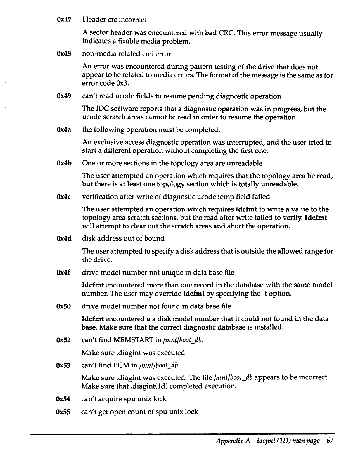
Ox47
Header ere incorrect
A sector header
was encountered with bad CRC. This error message usually
indicates a fixable media problem.
Ox48
non-media related cmi error
An
error was encountered during pattern testing of the drive that does
not
appear to be related to media errors. The format of the message is the same as for
error code
Ox3.
Ox49
can't read ucode fields to resume pending diagnostic operation
The IDC software reports that a diagnostic operation was
in
progress,
but
the
ucode scratch areas cannot be read
in
order to resume the operation.
Ox4a
the following operation must be completed.
An
exclusive access diagnostic operation was interrupted,
and
the
user
tried to
start a different operation without completing the first one.
Ox4b
One
or
more sections in the topology area are unreadable
The user attempted
an
operation which requires that the topology area
be
read,
but
there is at least one topology section which is totally unreadable.
Ox4c
verification after write of diagnostic ucode temp field failed
The user attempted
an
operation which requires idcfmt to write a value to the
topology area scratch sections,
but
the read after write failed to verify.
Idcfmt
will attempt to clear
out
the scratch areas and abort the operation.
Ox4d
disk address
out
of bound
The user attempted to specify a disk address that is outside the allowed range for
the drive.
Ox4f
drive model number not unique in data base file
Idcfmt encountered more than one record
in
the database with the same model
number. The user may override idcfmt
by
specifying the -t option.
OxSO
drive model number not found in data base file
Idcfmt encountered a a disk model number that it could
not
found
in
the
data
base. Make sure that the correct diagnostic database is installed.
Ox52
can't find
MEMSTART
in
/mnt/boot_db.
Make sure .diagint was executed
Ox53
can't find PCM in
/mnt/boot_db.
Make sure .diagint
was
executed. The file
/mnt/boot_db
appears to
be
incorrect.
Make sure that .diagint(ld) completed execution.
Ox54
can't acquire
spu
unix lock
Ox55
can't get
open
count of
spu
unix lock
Appendix
A
idcfmt<1D)
man
page
67
Page 79
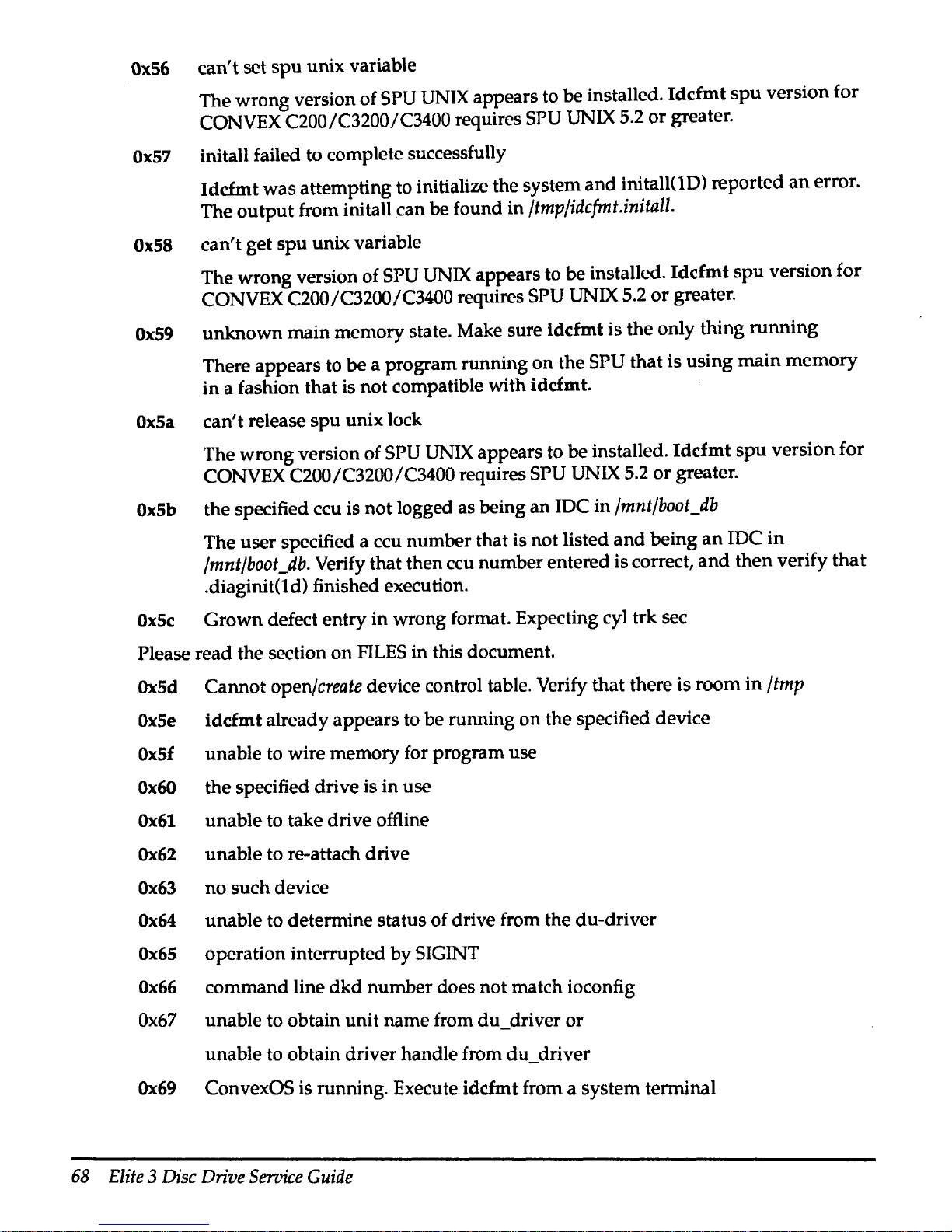
Ox56
can't set
spu
unix variable
The wrong version of
SPU
UNIX
appears to be installed. Idcfmt
spu
version for
CONVEX C200/C3200/C3400 requires
SPU
UNIX
5.2
or
greater.
Ox57
initall failed to complete successfully
Idcfmt was attempting to initialize the system
and
initall(lD) reported
an
error.
The output from initall can
be found in
/tmp/idcfmt.initall.
Ox58
can't get spu unix variable
The wrong version of
SPU
UNIX
appears to be installed.
Iddmt
spu version for
CONVEX C200/C3200/C3400 requires
SPU
UNIX 5.2
or
greater.
Ox59
unknown main memory state. Make sure idcfmt is the only thing running
There appears to be a program running on the
SPU that is using main memory
in a fashion that is not compatible with
idcfmt.
OxSa
can't release spu unix lock
The wrong version of
SPU
UNIX
appears to be installed. Idcfmt spu version for
CONVEX C200/C3200/C3400 requires SPU UNIX
5.2
or
greater.
OxSb
the specified ccu is not logged as being an IDC in
/mnt/boot_db
The user specified a ccu number that is not listed
and
being
an
IDC
in
/mnt/boot_db.
Verify that then ccu number entered is correct,
and
then verify
that
.diaginit(td) finished execution.
OxSc
Grown defect entry in wrong format. Expecting cyl trk sec
Please read the section on
FILES
in this document.
OxSd
Cannot
open/create
device control table. Verify that there is room in
/tmp
OxSe
idcfmt already appears to be running
on
the specified device
OxSf
unable to wire memory for program use
Ox60
the specified drive is in use
Ox61
unable to take drive offline
Ox62
unable to re-attach drive
Ox63
no
such device
Ox64
unable to determine status of drive from the du-driver
Ox65
operation interrupted by SIGINT
Ox66
command line
dkd
number does not match ioconfig
Ox67
unable to obtain unit name from du_driver
or
unable to obtain driver handle from du_driver
Ox69
ConvexOS is running. Execute idcfmt from a system terminal
68
Elite
3
Disc
Drive
Service
Guide
Page 80

FILES
Ox6a
Slipped sector
not
written
to
top
cyl defect list
Ox6b
Attempt
to
write
topology cylinder
grown
defects section failed
Ox6c
None
of
the
enabled
drives
were successfully initialized
Format
of
manufacturers
defect
file
When
the
user
specifies
the
-m
option
on
the
command
line,
idcfmt
expects
the
specified
file
pathname
to
point
to
an
ascii file
with
the
following
data.
Cylinder
track byte_count_from_index defect_length_in_bits
There
should
be
one
line
in
the
file for each defect entry. All
numbers
are
in
decimal.
Due
the
peculiarity
of
the
way
defect
data
is
encoded
for
multiple
heads
per
track
disk
drives,
it is extremely difficult to
guess
what
sector
an
error
will
occur
for a
given
byte
count
from
index.
The
-m
option
is
provided
so
that
the
user
can
recover defect
data
from
a
paper
copy.
If
the
user
wishes
to force a sector to
be
treated
as
defective
during
the
initial
format
of
the
drive,
he
should
make
an
entry
in
the
grown
defect table.
Format
of
grown
defect
file
When
the
user
specifies
the
-g
option
on
the
command
line,
idcfmt
expects
the
argument
after
the
-g
to
point
to ale
in
the
following format:
Cylinder
track sector
There
should
be
one
line
in
the
file for each defective sector. All
numbers
are
in
decimal.
Format
of
pattern
The
-p
option
on
the
command
line is
used
to
change
the
default
set
of
patterns
used
during
pattern
testing
of a disk
drive. The
argument
after
the
-p
flag
should
point
to
ale
that
contains a
set
of hex
digits
that
will
be
used
to
pattern
test
the
drive.
Thus,
ale
containing
I 4 c 9abdef01
will
cause
four
patterns
to
be
used
for
pattern
testing.
The
first
pattern
will fill
the
disk
with
all
Oxllllllll,
the
second
with
all Ox44444444,
the
third
with
Oxcccccccc,
and
finally,
Ox9abcdef01.
It
should
be
noted
that
entering
a single hex
digit
of
1 is
the
same
as
entering
it
as
11,
1111,
and
11111111.
It
is also possible to
enter a pattern
of
23456789a
and
then
the
pattern
generated
will
be
23456789
a2345678
9a234567
89a23456
789a2345
...
When
the
pattern
is specified
with
a length of 1, 2, 4
or
8 hex digits,
the
initialization
of
the
data
buffer
is
much
faster. Specifying a
pattern
as
111
instead
of
1, 11,
1111,
or
11111111
results
in
over
16x
the
amount
of
time
needed
to initialize
the
buffer.
Appendix A idcfmt
(1D)
man
page
69
Page 81
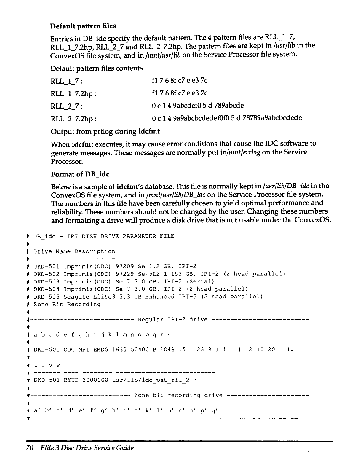
Default
pattern
files
Entries in DB_idc specify the default pattern. The 4 pattern files are RLL_1_7,
RLL_1_7.2hp, RLL_2_7
and
RLL_2_7.2hp. The pattern files are
kept
in
/usr/lib
in
the
ConvexOS file system,
and
in
/mnt/usr/lib
on
the Service Processor file system.
Default
pattern
files contents
RLL_1_7:
RLL_1_7.2hp :
RLL_2_7:
RLL_2_7.2hp :
fl
7 6
Sf
c7 e e3
7c
fl
7 6
Sf
c7 e e3
7c
0 c 1 4 9abcdef0 5 d 789abcde
0 c 1 4 9a9abcbcdedef0f0 5 d 78789a9abcbcdede
Output
from prtlog
during
idcfmt
When idcfmt executes,
it
may
cause error conditions that cause
the
~DC
software to
generate messages. These messages are normally
put
in/mnt/errlog
on
the
Service
Processor.
Format
of
DB_idc
Below is a sample of idcfmt' s database. This file is normally kept
in
/usr/lib/DB
_idc
in
the
ConvexOS file system,
and
in
/mnt/usr/lib/DB_idc
on
the Service Processor file system.
The numbers
in
this file have been carefully chosen to yield optimal performance
and
reliability. These numbers should not be changed
by
the user. Changing these
numbers
and
formatting a drive will produce a disk drive that is
not
usable
under
the
ConvexOS.
#
DB
idc -!PI
DISK
DRIVE
PARAMETER
FILE
*
i
Drive
Name
Description
*
----------
-----------
DKD-501
Imprimis(CDC)
97209 Se
1.2
GB.
IPI-2
DKD-502
Imprimis(CDC)
97229
Se-512
1.153
GB.
IPI-2
(2
head
parallel)
DKD-503
Imprimis(CDC)
Se 7
3.0
GB.
IPI-2
(Serial)
*
*
*
*
*
*
*
DKD-504
Imprimis(CDC)
Se 7
3.0
GB.
IPI-2
(2
head
parallel)
DKD-505
Seagate
Elite3
3.3
GB
Enhanced
IPI-2
(2
head
parallel)
Zone
Bit
Recording
#----------------------------
Regular
IPI-2
drive
--------------------------
*
*
a b c d e f g h i j k 1 m n o p q r s
*
-------
------------
* DKD-501
CDC
MPI
EMD5
1635 50400 P 2048 15 1 23 9 1 1 1 1 12 10 20 1 10
*
* t u v w
*
-------
# DKD-501
BYTE
3000000
usr/lib/idc_pat_rll_2-7
*
#--------------------------- Zone
bit
recording
drive
----------------------
*
#
a'
b'
c'
d'
e'
f'
g'
h'
i'
j'
k'
l'
m'
n'
o'
p'
q'
*
-------
------------
--
70
Elite 3 Disc
Drive
Service
Guide
Page 82

# DKD-505
SEAG2HD
E3L2
18
2738
2048
10 2 15
2 1 1 1
12
0 0 2
20
#
#
r'
SI
t I U I
#
-------
# DKD-505
BYTE
16777200
usr/lib/RLL_l_7.2hp
#
#
#
#
#
v'
w'
x'
y'
0
DKD-505
0
z'
0'
l'
200
72799
p
62
#==========================================================================
1
DKD-501
CDC
MPI
EMD5
1635
50400 p 2048
15 1 23
9
1 1 1 1
12
10
20 1 10
-
2 DKD-501
BYTE
3000000
usr/lib/RLL
2 7
1
DKD-502
CDC
MPI
S5L2
1635
50400 p 2048
7
2
45
15
1
1 1 1
12
14
34
2
10
-
2 DKD-502
BYTE
6000000
usr/lib/RLL
2
7.2hp
1
DKD-501 SEAGMPI
EMD5
1635
50400 p 2048
15 1 23
9 1 1 1
1
12
10
20
1
10
-
2 DKD-501
BYTE
3000000
usr/lib/RLL
2 7
1
DKD-502 SEAGMPI
S5L2
1635
50400 p 2048
7
2
45
15
1 1 1
1
12
14
34
2
10
2 DKD-502
BYTE
6000000
usr/lib/RLL
2
7.2hp
1 DKD-503
SEAGlHD
S7Kl
2655
63840
p
2048
19 1 29
15
1 1 1 1
12
11
40 1 20
-
2 DKD-503
BYTE
4644360
usr/lib/RLL
1
7
1 DKD-504
SEAG2HD
S7L2
2655
63840 p 2048
9 2
56
15
1 1 1 1
12
2
40 2 20
2 DKD-504
BYTE
9288720
usr/lib/RLL_1_7.2hp
#==========================================================================
3 DKD-505
SEAG2HD
E3L2
18
2738
2048
10 2 15
2 1 1 1
12
0 0 2
20
4 DKD-505
BYTE
16777200
usr/lib/RLL_l_7.2hp
5 0 DKD-505 0
200
72799
P 62
5
5
5
5
5
5
5
5
5
5
5
5
5
1 DKD-505
2 DKD-505
3
DKD-505
4 DKD-505
5 DKD-505
6 DKD-505
7 DKD-505
8 DKD-505
9 DKD-505
10
DKD-505
11
DKD-505
12 DKD-505
13
DKD-505
201
417
71399
p
61
418
628
69999
p
60
629
810
68599
p
59
811
973
67199 p 57
974
1131
65799
p
56
1132 1288
64399 p 55
1289 1425
62999 p 54
1426 1550
61599 p 53
1551
1658
1659
1769
1770
1871
1872
1968
1969
2095
60199
p
58799
57399
55999
54599
51
p
50
p
49
p
48
p 47
14 DKD-505
2096
2299
53199
5 p
45
5
15
DKD-505
2300
2424
51799
P 44
5
16
DKD-505
2425 2561
50399
P
43
5
17
DKD-505
2562
2737
48999
P 42
#===========================================================================
#
#
LEGEND
for
regular
IPI-2
drives
# a -
drive
name -Must
be
an
unique
DKD-NNN
number.
# b -
mfg
id/model
number
#
#
mfg
id
- 4
bytes
obtained
by
read
cog
of
drive,
eg.
"CDC_"
#
model
number
- 8
bytes
obtained
by
read
cog
of
drive,
eg.
"MPI
S5L2"
#
Appendix A idcfmt
(1D)
man
page
71
Page 83

#
Note:
see
product
speccation
manual
of
IPI-2
drive
for
these
info.
#
Replace
any
spaces
in
the
field
with
underscore
characters.
#
# c -
Total
number
of
cylinders
per
unit
# d - Number
of
bytes
per
track
(see
e)
#
# e - P - (
deld
is
the
physical
bytes
per
track
)
# L - (
deld
is
the
logical
bytes
per
track)
# The
logical
bytes
per
track
is
the
physical
bytes
per
track
multiplied
#
by
the
number
of
heads
per
logical
track.
eg.
DKD-502
entry
can
have
an
#
alternate
speccation
of
'100800'
for
the d field
and
'L'
for
the
#
eeld.
#
# f
- Number
of
data
bytes
per
sector
#
g - Number
of
logical
tracks
per
cylinder
#
h
- Number
of
heads
per
logical
track
#
i -
Number
of
sectors
per
logical
track
#
j - Number
of
spare
sectors
per
user
cylinder
#
k
- Number
of
cylinders
reserved
for
diagnostic
use
#
l
- Number
of
cylinders
reserved
for
manufacturers
defect
map
# m -
Number
of
cylinders
reserved
for
describing
drive
topology
# n
- Number
of
cylinders
#
# o -
Header
size
# p -
Header
gap
# q -
Data
gap
reserved
for
spares.
# r -
Ecc
interleave
(options
are
O,
1, 2 or
4)
# s - Number
of
spare
sectors
per
topology
cylinder
# t -
This
should
have
the
same
DKD
name
as
line
1
of
the
entry.
# u -
Data
Interleave,
applicable
only
to
parallel
heads
(BIT,
BYTE,
WORD)
# v -
Drive
data
transfer
rate
in
bytes
# w -
pathname
of
ascii
hex
patternle.
If
the
pathname
starts
#
with a /,
it
will
be
used
as
is.
If
it
does
not,
a
"/mnt/"
#
will
be
prepended
to
the
pathname
when on
the
spu,
and
a
#
"!"
will
be
prepended
when on
the
JP.
#
#---------------------------------------------------------------------------
#
LEGEND
for
enhanced
IPI-2
(zone
bit
recording)
drives
#
#
a' -Drive
name - Must
be
an
unique
DKD-NNN
number.
#
b' -Mfg
id/model
number
#
c'
- Number
of
zones
in
drive
#
d'
-
Total
number
of
cylinders
per
unit
#
e'
- Number
of
data
bytes
per
sector
(2K
sector
size)
#
f'
- Number
of
logical
tracks
per
cylinder
#
g'
- Number
of
heads
per
logical
track
#
h'
- Number
of
spare
sectors
per
user
cylinder
#
i'
- Number
of
cylinders
reserved
for
diagnostic
use
#
j'
- Number
of
cylinders
reserved
for
manufacturers
defect
map
#
k'
- Number
of
cylinders
reserved
for
describing
drive
topology
#
l'
- Number
of
cylinders
reserved
for
spares.
#
m'
Header
size
#
n'
-
Header
gap
(in
50
nanoseconds
increments
for
buffered
drive)
72
Elite 3 Disc
Drive
Service
Guide
Page 84

,,
#
*Use
recommended
MTD
value
of
OxlOO.
OxlOO
* 50 =
12.8
microseconds
#
o' -Data
gap
(in
50
nanoseconds
increments
for
buffered
drive)
# * Use
recommended
MTD
value
of
OxlOO.
OxlOO
* 50 =
12.8
microseconds
#
p' -Ecc
interleave
(options
are
O,
1, 2 or
4)
#
q'
- Number
of
spare
sectors
per
topology
cylinder
#
r'
-
This
should
have
the
same
DKD
name
as
line
1
of
the
entry.
#
s'
-
Data
Interleave,
applicable
only
to
parallel
heads
(BIT,
BYTE,
WORD)
#
t'
-
Drive
data
transfer
rate
in
bytes,
assume
16M
xfer
rate
#
u' -pathname
of
ascii
hex
patternle.
If
the
pathname
starts
#
with
a
!,
it
will
be
used
as
is.
If
it
does
not,
a
"/mnt/"
#
will
be
prepended
to
the
pathname
when on
the
spu,
and
a
#
"/"
will
be
prepended
when on
the
JP.
#
v'
- Zone
number,
from 0 to
(number
of
zones
- 1)
#
w'
-
This
should
have
the
same
DKD
name
as
previous
entry.
#
x' -Starting
cylinder
in
this
zone
#
y' -Ending
cylinder
in
this
zone
#
z'
-
number
of
bytes
per
track
(see
0')
#
0'
- P - (
z'eld
is
the
physical
bytes
per
track
# L - (
z'eld
is
the
logical
bytes
per
track)
#
l'
- Number
of
sectors
per
logical
track
#----------------------------------------------------------------------------
BUGS
No
known
bugs
as
of
04/93.
Appendix A idcfmt
(1D)
man
page
73
Page 85

Index
Symbols
/etc/disktab
30
Elite 3 disc
drive
entry
30
Entry description
30
/ioconfig file 28
A
Elite 3
en
tries
28
Example entries 29
associated
documents
xii
c
control board
jumpers
6
description 7
location 6
pin assignment 7
ConvexOS integration 27
ConvexOS requirements 27
CRC
errors 44
D
damage
claims 14
de
power
requirements 3
determining disc usage 46
E
ECC
errors 44
electrostatic discharge protection
xiii
Elite 3 disc
drive
error codes 33
description 34
Elite 3 disc
drive
specifications 1
expansion cabinet
drive
locations for 16 drives
25
expansion cabinet
drive
locations for 32 drives
24
F
fault
symptom
code
(FSC) 35, 44
descriptions 36
field descriptions 35
format 35
reported
during
autoconf 45
reported from
unformatted
disc 45
FCC
Notice
xiii
1/0
board
jumpers
8
locations 8
pin assignment 8
IDC bulkhead
port
assignments
C3200/3400 18
C3800 19
JDC
drive connections
23
idcfmt
formatting
disc
drive
32
manpage
55
bugs
73
commands 57
error codes
6.3
examples
61
files
69
layout
of
an
idc disk
62
options
55
synopsis 55
slipping sectors 44
verify format
31
illustrated
parts
breakdown
(IPB) 52
inspection
13
installation
14
L
cabling a single
drive
17
cabling multiple disc drives 20
disc tray 14
Elite
3 chassis 16
power
strip 14
preparations 14
logical
unit
number
28
N
notational conventions
xi
0
ordering
documents
xii
Index
75
Page 86

p
physical configurations 22
power
supply
cable
pin
assignments
11
component locations
10
voltage specifications 10
power
supply
specifications
input
voltage 9
R
operational environment 9
output
voltage adjustability 9
weight 9
reading Elite 3 disc error codes
33
removal
and
replacement procedures
48
air
filter
51
s
Elite 3 chassis
48
Elite 3 disc drive
48
fan assembly 50
operator panel 49
power
supply
49
sector errors 44
specifications
capacity
1
T
environmental requirements 2
latency 2
physical
2
seek
time 2
size 1
start
time 2
transfer rate 2
technical assistance
xiii
troubleshooting
33
u
unpacking
13
v
VVM messages 45
device failure message
45
successful reconstruction
45
76
Elite 3 Disc
Drive
Service
Guide
Page 87

1111111111
I
IHI
 Loading...