

Converters.TV CDPS-UH4H1HFS Operation Manual
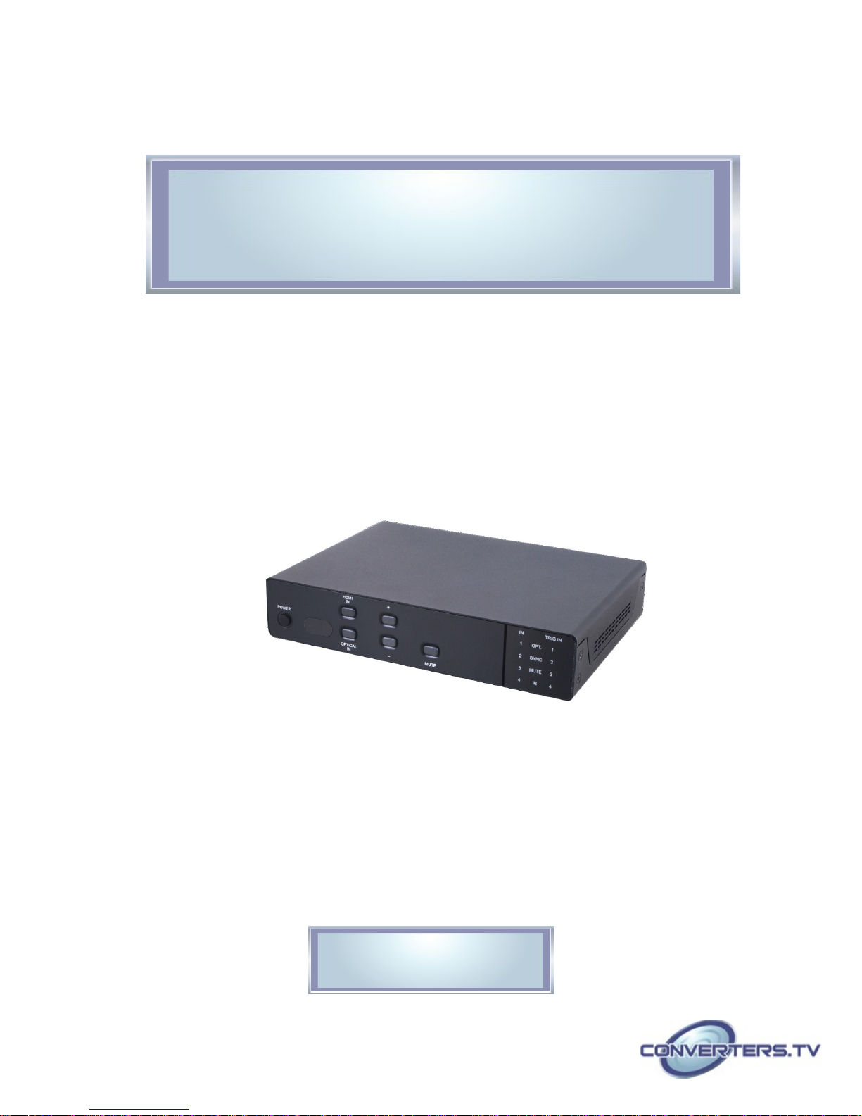
4 x 1 HDMI UHD Switcher with Fast
Switching and Control System - # 15369
Operation Manual

Introduction
Applications
Features
This 4 by 1 HDMI UHD Switcher allows four HDMI sources to be routed to
an HDMI display. The Fast Switching Technology greatly reduces the time
required to swap between inputs. The Control System not only provides
direct control but also indirect control interfaces for all your connected
devices. Supporting traditional direct control systems like IR, Relay and DC
and indirect control systems like IR Learning, RS-232, Telnet/WebGUI
controls, it allows the user with PC or APP based control systems great
flexibility over devices. The operation of the system can be easily managed
through software application on PC/Laptop or APP on mobile devices, onpanel buttons, IR remote control, RS-232, Telnet or Ethernet protocols.
• Showroom display & control
• Educational demo & control
• Home entertainment & security control
• HDMI (with 3D & 4K2K supported) and HDCP compliant
System
Requirements
• Supports HDTV resolutions up to 4Kx2K (3840×2160@24/25/30Hz
& 50/60Hz with YUV420 or 4096×2160@24Hz & 50/60Hz with
YUV420)
• Supports HDMI data rate from 300Mbps to 3Gbps and ‘Deep Color’
up to 1080p/36-bit
• Supports simultaneous audio outputs on both HDMI and analog R/L
• HDMI inputs support ‘Standard’ and ‘Apple’ HDCP modes. Selecting
‘Apple mode guarantees the compatibility of Apple devices
• Support RS-232, IR, Telnet and WebGUI controls
• Supports four inputs control with voltage of 0~3.3v
• Supports control system with 5 IR outputs, 4 Trigger inputs, 4 Relay
outputs and 2 COM ports
• Supports COM port’s Baud rate from 4800~115200bps
• Supports auto source detection with the latest input signal
• Speaker supports LPCM 2CH
Input source equipment such as DVD/Blu-ray player and output HD
display/Monitor with HDMI cables. Control system input sources such as
light, TV, power switch and etc... and PC/Laptop for output control.
Operation
Controls and Front Panel
Functions
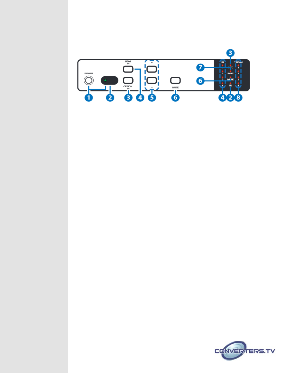
1. POWER Button and LED:
Press this button to switch On or set the device to standby mode. The LED
will illuminate in green when the device is power On and if it is switched to
standby mode the LED will turn red.
Note:
For IP reset from Static to DHCP mode, press and hold the power button
for 3 seconds while the device is ON and the LED will blink once.
2. IR Window and LED:
This IR Receiver receives the remote control signal from the package
included remote control only and the LED will blink when IR signal is
receiving.
3. OPTICAL IN Button and LED:
Press this button to select output audio from optical source and the LED
will illuminate.
4. HDMI IN Button and LEDs 1~4:
Press this button to select an input from the input sources 1~4 and the
LED will illuminate according to the selection.
Note:
For firmware update, press and hold this button then plug-in the AC power
into the device and then the USB flash driver with updated firmware(s)
inside.
5. +/-:
Press these buttons to adjust up/down the output audio sound.
6. MUTE Button and LED:
Press this button to mute the SPEAKER output sound. The LED will
illuminate when audio is set to mute either from front-panel’s mute button,
IR, Telnet, WebGUI or RS-232 and when the input audio format is nonPCM the LED will be blinking. Press it again to unmute and the LED will
switch off.
Note:
For restore back to factory default, press and hold this button then plug-in
the AC power into the device.
7. SYNC LED:
This LED will illuminate when the input detected HDMI signal from source
equipment.
8. TRIGGER IN LED 1~4:
These LEDs will illuminate when IN connection obtain active low DC
voltage of 0~0.5V which is also when signals has been triggered. Under
normal operation, the voltage is about
3.3V.
Rear Panel
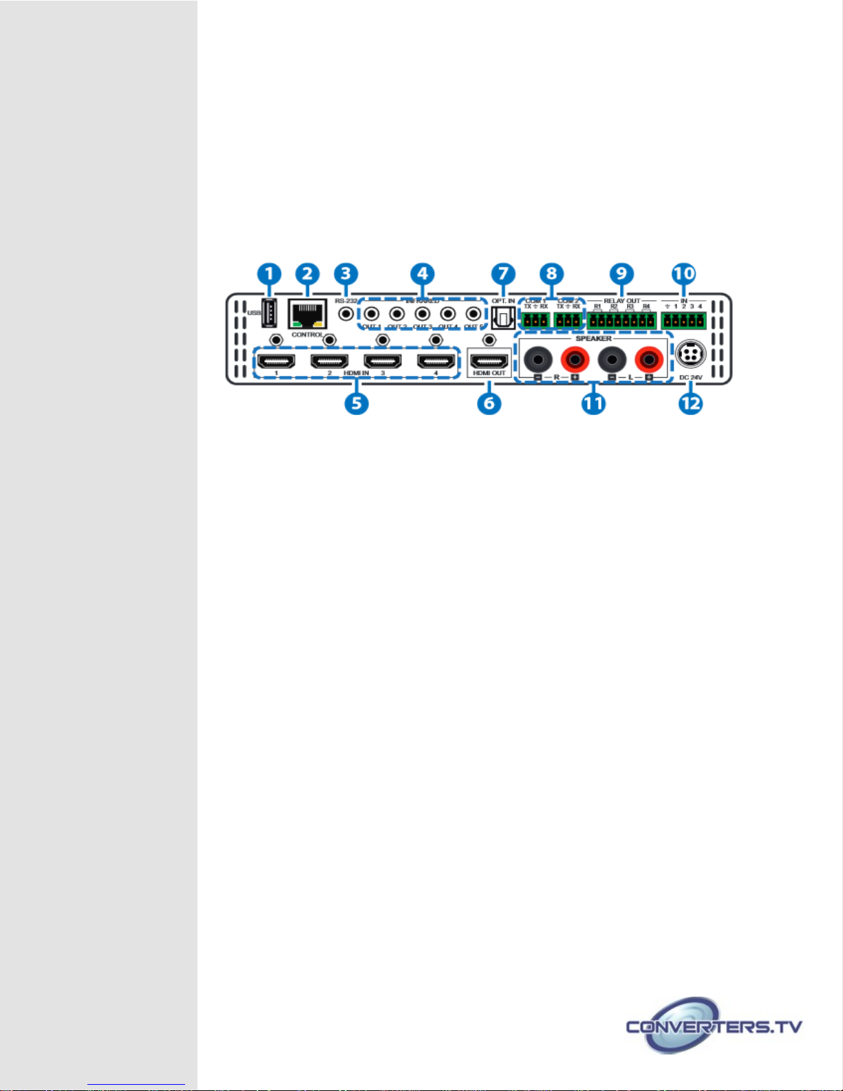
1. USB:
This slot is reserved for firmware update use only.
2. CONTROL:
Connect from PC/Laptop with active internet service for Telnet or WebGUI
control with RJ-45 terminated cable.
3. RS-232:
Connect from PC/Laptop for RS-232 command sending to control the
device.
4. INFRARED OUT 1~5:
Connect with IR Blaster for IR signal transmitting.
5. HDMI IN:
Connect from source equipment such as Blu-ray/DVD/PS3 players, SetTop-Box or any HDMI equipped source device for input signal sending. This
device has source auto-detection function from the latest input and when
the latest input has been pulled out it will follow the number sequence.
6. HDMI OUT:
Connect to HDMI TV/display or HD Amplifier for output image and or audio
display.
7. OPT. IN:
This slot is to connect with audio source equipment such as Blu-ray/PS3
player for audio signal input through optical cable.
8. COM 1~2:
Connect from other devices that are to be controlled with 3.5mm terminal
block cable for control through RS-232 commands.
9. RELAY OUT R1~4:
Connect with control device’s DC power such as curtain or projector screen.
10. TRIGGER IN 1~4:
Connect with event device’s signal lines such as window security alarm,
door switch, and etc... for trigger signal sending back to Control System and
or run the macro commands.
Remote Control
11. SPEAKER R/L:
These slots are to connect with analog speakers through banana jack
cables for audio signal output from HDMI or Optical.
Note:
These slots only support LPMC 2CH signal, other signals will be mute
automatically.
12. DC 24V:
Connect the adaptor included in the package and connect to AC wall outlet
for power supply.
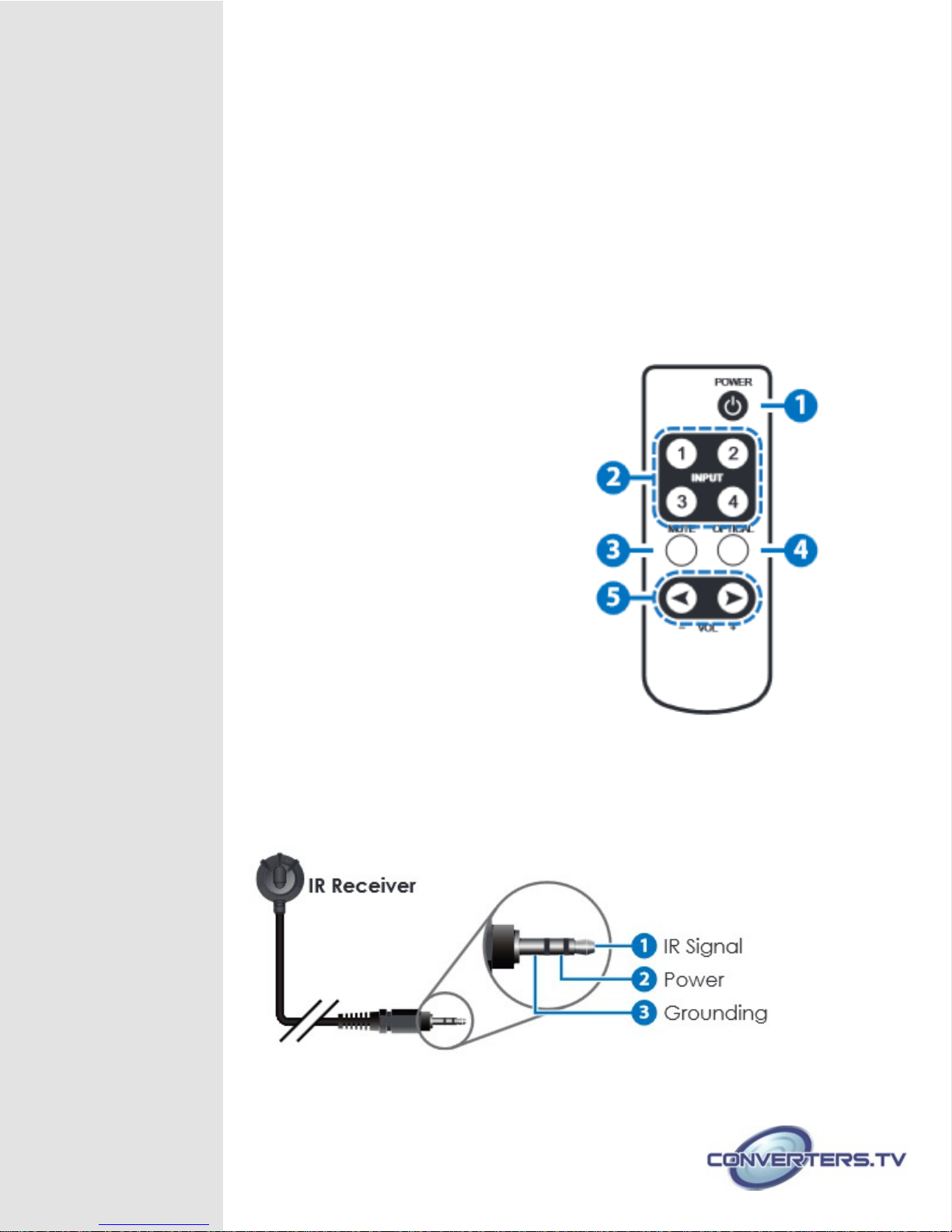
1. POWER:
Press this button to switch On or
set the device to standby mode.
2. INPUT 1~4:
Press these buttons once a
time to select or switch input source.
3. MUTE:
Press this button to mute the
SPEAKER output sound press it again to
unmute.
4. OPTICAL:
Press this button to select audio
from optical input source.
5. -/← VOL +/→:
Press these buttons to
move down/up the output speaker
volume.
IR Pin Definitions
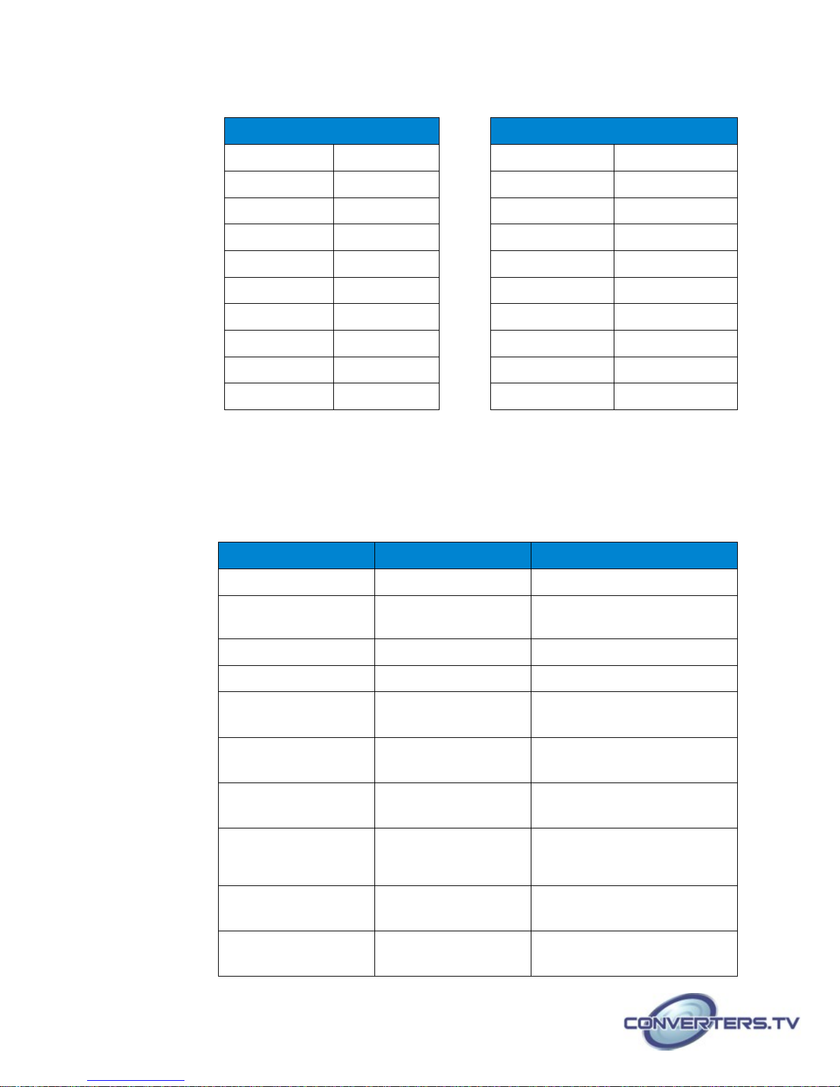
RS-232 Protocols
Switch Remote Control
PIN Assignment PIN Assignment
1 NC 1 NC
2 TxD 2 RxD
3 RxD ► 3 TxD
4 NC 4 NC
5 GND ◄ 5 GND
6 NC 6 NC
7 NC 7 NC
8 NC 8 NC
9 NC 9 NC
Baud Rate: 115200bps Data bit: 8 bits
Parity: None Flow Control: None
Stop Bit: 1
Telnet & RS-232
Commands
Command Name Description Description of Parameter
HELP (?)
HELP N Show Description Of
Show Command List NONE
N = COMMAND NAME
Command
P0 Power Off (Standby) NONE
P1 Power On NONE
MUTE
Show AMP Mute
NONE
Mode
MUTE N Set AMP Mute
N=0 (UNMUTE), 1 (MUTE)
Mode N
SPEAKER
Show Speaker Input
NONE
Source
SPEAKER N Set Speaker Input
Source
AUDIOFMT
Show EDID Audio
N=0 (HDMI),
1=(OPTICAL)
NONE
Format
AUDIOFMT N Set EDID Audio
N=0 (PCM), 1 (BYPASS)
Format N
 Loading...