

Converters.TV 986 Operation Manual
8×8 HDMI over Single CAT5e/6/7
Matrix with PoE ID# 986
Operation Manual

Introduction
Features
The HDBaseT™ 8 by 8 HDMI Matrix over CAT5e/6/7 supports the
transmission of video (resolutions up to 1080p Full HD and
1920×1200@60Hz) and multi-channel digital audio from eight high definition
sources to eight outputs over a single CAT5e/6/7 cable (up to 100m) for
each output. It supports high resolution digital audio formats such as LPCM
7.1CH, Dolby TrueHD, Dolby Digital Plus and DTS-HD Master Audio as well
as 3D content that can be displayed when connecting a 3DTV and 3D
source. The matrix can be controlled via IR, RS-232, Telnet or Web GUI.
Power over Ethernet (PoE) support means that compatible receivers do not
need their own seperate power supplies, allowing for greater flexibility in
installations.
• HDMI, HDCP1.1 and DVI compliant
• Supports HDMI 3D features
• Supports resolutions VGA~WUXGA and 480i~1080p dependent
upon the output display’s EDID settings
• Supports 3D signal display dependent upon the output display EDID
settings
• Supports PoE (Power over Ethernet) on compatible receivers only
• Supports HDMI input up to 15 meters at 8-bit resolution or 10 meters
at 12-bit resolution
• Supports bi-directional IR to and from input and output locations
• Supports control via RS-232, IR remote, on-panel buttons and IP
(Telnet & Web GUI)
• 2U size design
• Supports external and internal EDID settings
• Supports LPCM 7.1CH, Dolby TrueHD, Dolby Digital Plus and DTS-
HD
• Master Audio transmission
Note:
1. The PoE function is designed for powering compatible receiver
units only—non-PoE receivers will need their own power supply.
Receivers of another brand may not be compatible.
.
2. Do not connect the CONTROL port to CAT outputs of this device
or to CAT inputs or receiver. Doing so may demage the unit.
Applications
● HDMI Matrix System
● Video/TV wall display and control
● Security surveillance and control
● Commercial advertising, display and control
● University lecture hall, display and control
● Retail sales and demonstration
System Requirements
• HDMI equipped source devices, connect with HDMI cables or
• HDMI equipped displays (TVs or monitors) or HDMI equipped
• Industry standard CAT5e/6/7 cables
• HDBaseT™ Receivers (CH-506RX, CH-507RX or CH-1109RX)
Operation Controls
and Functions
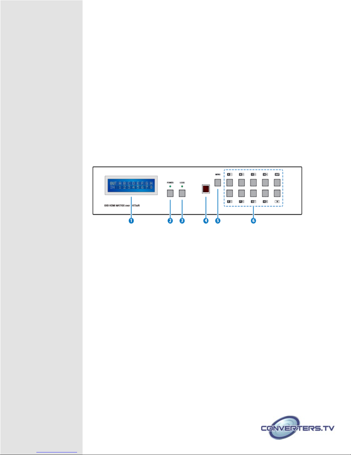
Front Panel
DVI equipped source, connect with DVI to HDMI cables
AV receivers, connected with HDMI cables
1 LCM:
Displays the setting information of each input and output
setting.
2 POWER:
Press this button to power the device on/off. The LED will
illuminate green when the power is on, red when it is in 'Standby'
mode.
3 LOCK:
Press this button to lock all the buttons on the panel; press
again to unlock. The LED will illuminate green when locked.
4 IR:
IR Receiver window (accepts the remote control signal of this
device only) with IR frequency of 38
kHz.
5 MENU:
Press this button to access the LCM menu system, from
here EDID settings can be managed and IP system settings are
displayed.
6 1~8/A~H and OUT/IN:
Press the OUT or IN button to select the
output or input mode and then press the required number button
to make the selection accordingly.
For example, if outputs A~D need to be set to input 1 and outputs
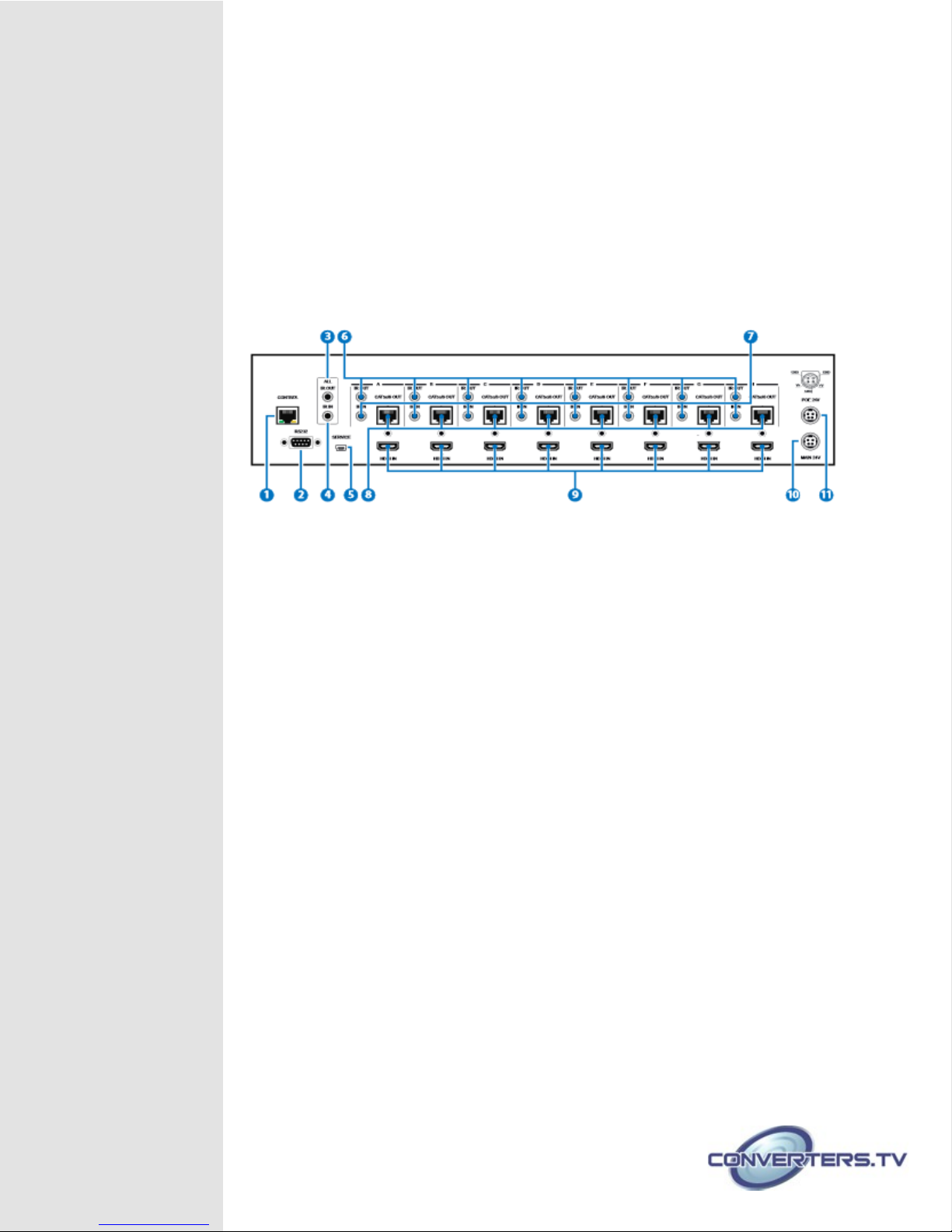
Back Panel
E~H need to be set to input 2, then the following sequence of
button presses need to be performed:
Press: OUT →A→B→C→D→IN→1→MENU,
and then press: OUT→E→F→G→H→IN→2→MENU.
Note: If the MENU button is not pressed the selection will not be
changed
1 CONTROL:
This port is the link for Telnet or Web GUI controls, connect
to an active Ethernet link with an RJ45 terminated cable (for further
details on IP control, please refer to sections 6.8 & 6.9).
Warning: Please do not connect this port directly to the PC/Laptop as the
Telnet function will not work.
2 RS-232:
Connect to a PC or control system with D-Sub 9-pin cable
for control of the matrix via RS-232 commands (please refer to
Section 6.7 for a list of commands).
3 ALL IR OUT:
Connect to the IR blaster for IR signal transmission to the
source devices. Place the IR blaster in direct line-of-sight of the
equipment to be controlled. All signals received from the display
side will be relayed to the source devices.
4 ALL IR IN:
Connect to the IR extender for IR signal reception. Ensure
that the remote being used is within the direct line-of-sight of the IR
extender. It will transmit all signals received through the IR ALL OUT.
5 SERVICE:
Manufacturer use only.
6 IR OUT A~H:
Connect to the IR blasters for IR signal transmission.
Place the IR blaster in direct line-of-sight of the equipment to be
controlled. It will transmit the IR signal received from the receiver
side according to the selected input.
7 IR IN 1~8:
Connect to the IR extenders for IR signal reception. Ensure
 Loading...